Embed Size (px)
Citation preview

G Millar
168 Insight Vol 48 No 3 March 2006
1. Introduction
The application of NDT can sometimes become a little routine, perhaps even boring. This is as true in the aerospace industry as it is in any other. Occasionally, however, you see something unusual, unexpected, or out of the ordinary that makes you do a double-take and think ‘that’s a strange one’. This happened recently on a major wing teardown inspection at Airbus at Filton and it is considered worth passing on both for general interest and for information. Before we go into details, however, it is worth describing what a teardown inspection entails and why it is done.
2. Wing teardown inspection
Teardown inspections are required by airworthiness authorities to support the findings of major fatigue tests on new aircraft models or major derivatives. The major fatigue tests involve a complete airframe undergoing fatigue cycling in a rig under computer control. The computer program controls hydraulic jacks which subject the structure to the whole spectrum of stresses that it will see in service, such as those induced by taxiing, take off, climb, turbulence, descent, landing (including heavy landing) and braking. This will be done with the rig running day and night for many months until it reaches the point where the structure has absorbed over twice its planned fatigue life in line with the agreed airworthiness agencies’ requirements. This is much more than the aircraft in service with airlines should ever see. The spectrum will also include some extreme cases such as the 2 m wing deflection shown in Figure 1.
Periodically, the rig is stopped and teams of inspectors check for damage visually and sometimes with NDT methods. Any damage is recorded and monitored. Once the structure has exceeded one fatigue life, damages of various types can be expected to appear. At the end of the test, a large amount of data will have been generated about where damages occur and how fast they grow. It will be known, however, that other damages will have gone unreported because they are too small to be detected with the structure assembled. Small damages like these which develop late in the test are unlikely to occur in flying aircraft, which will not experience the same amount of fatigue. Nonetheless, manufacturers and airworthiness authorities need to get all the information possible
from the fatigue test and that is where the teardown inspection comes in. Large sections such as the wings will be cut into six or seven parts and transported to the inspection site.
The teardown inspection is not a ‘blanket’ search but is directed to structural areas selected by the Fatigue and Damage Tolerance Group and detailed in a Test Definition document. The extent of the teardown (disassembly) includes the removal of the top and bottom wing skins and the separation of the individual skin panels. The engine pylon fittings will be removed from the front spar and the undercarriage fittings from the rear spar together with their respective reinforcing plates. The object is to give access to all the likely crack initiation sites that could not be inspected while the wing was in one piece with all the fasteners (bolts) installed. For a large aircraft like the A340-600, the wing sections take up a lot of floor space, as can be seen from Figure 2.
Inspections are carried out using procedures from the aircraft NDT manual or using special procedures developed and approved by the manufacturer’s NDT department. A dedicated team of
AEROSPACE INSPECTION
The ‘Strange One’ at the teardown
This paper describes an unusual indication obtained using rotating probe eddy current equipment for the inspection of an aerospace fatigue test structure. Commentary is given on the reason for conducting the fatigue test and the subsequent teardown inspection. A brief description of the rotating probe eddy current inspection method is given. The investigation of the unusual indication is described.
Geoff Millar started his NDT career in the RAF in the mid seventies and worked on a variety of military aircraft as well as the evaluation of advanced NDT equipment and new structural materials. This was followed by a spell as an instructor and finally Chief Instructor in the RAF School of NDT. On joining Airbus at Filton in 1987, he continued to work in NDT with an emphasis on ultrasonic immersion testing, airline procedures and teardown inspections. Geoff holds PCN Level 3 Aerospace certification in four methods and chairs the SBAC NDT Special Interest Group.
Figure 1. Wing deflection under test
Figure 2. Wing segments laid out for inspection
Insight Vol 48 No 3 March 2006 169
structural technicians do the disassembly which allows the NDT team to carry out the inspections. Both teams work on the teardown full time for between twelve to eighteen months, see Figures 3 and 4.
The extent of disassembly gives excellent access to the structure and so the majority of inspections can be done with high sensitivity methods such as eddy currents in the hole bores (see Figure 4) and the hole surrounds.
3. Rotating probe eddy current inspection
The vast majority of NDT inspections involve bolt hole bores. This is because cracks may start at the attachment points of skins and substructure where slight but repeated movement between the layers causes fretting around the attachment holes at the interface. This fretting acts as a stress raiser and cracks initiate at the interface, propagating up the hole and into the material. The easiest way to find these cracks is with rotating probe eddy currents (RPEC) where
a cylindrical probe is rotated in a tool (rotor) and inserted into the hole (see Figure 5). For readers not familiar with the method, a few outline details are given below.
3.1 Principle of operation
The probes contain two small coils mounted side-by-side in the end of the probe. These are wound differentially so that they will only respond to cracks running up and down the bore and not to the interfaces between the layers of material. This makes them very sensitive and able to inspect very close to the interfaces where cracks initiate. The standard sensitivity claimed is the reliable detection of cracks of 1.0 mm (0.39 in) and greater.
Cracks are detected because they obstruct the flow of eddy currents induced in the material surrounding the hole by the action of the AC current flowing through the coils. This obstruction alters the electrical impedance of the coil circuit when the coils pass over the crack. The change in impedance is displayed on a screen. When there is no crack present the screen shows a spot (flying dot) at its centre which remains relatively stable as the probe rotates and is inserted and withdrawn from the hole.
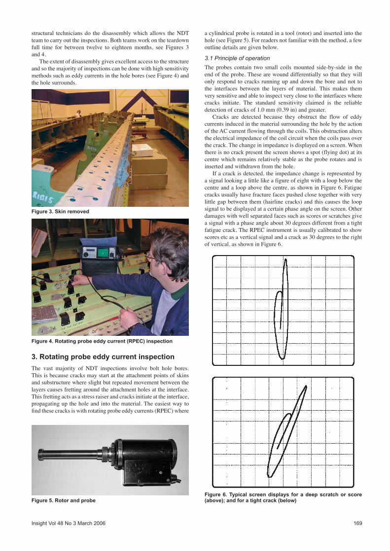
If a crack is detected, the impedance change is represented by a signal looking a little like a figure of eight with a loop below the centre and a loop above the centre, as shown in Figure 6. Fatigue cracks usually have fracture faces pushed close together with very little gap between them (hairline cracks) and this causes the loop signal to be displayed at a certain phase angle on the screen. Other damages with well separated faces such as scores or scratches give a signal with a phase angle about 30 degrees different from a tight fatigue crack. The RPEC instrument is usually calibrated to show scores etc as a vertical signal and a crack as 30 degrees to the right of vertical, as shown in Figure 6.
Figure 3. Skin removed
Figure 4. Rotating probe eddy current (RPEC) inspection
Figure 5. Rotor and probeFigure 6. Typical screen displays for a deep scratch or score (above); and for a tight crack (below)

170 Insight Vol 48 No 3 March 2006
This calibration is not universal and the signals may be set to appear at different angles depending on the procedure being followed. In the majority of cases this screen display makes it easy to distinguish between a genuine fatigue crack and minor damage such a scratches and scores.
In some cases, however, interpretation has to be done with great care as some indications that look like cracks may not be and some indications that look like scratches may be cracks. Good procedure writing and inspector experience are needed to make sure the correct interpretation is made. Most of the common ‘false call’ signals are well known to experienced inspectors who look out for signals with characteristic shapes. Occasionally, however, once in a while, there comes along a ‘Strange One’.
4. The Strange One
During a particularly fruitless search for a decent crack indication on the teardown structure, the ‘Strange One’ appeared. It was strange first of all because of its appearance on the screen which looked unusual, untypical and, well, strange, as shown in Figure 7.
It was certainly not a standard crack indication but neither was it a recognisable false call. It was relatively large which made it reportable and it had a right of vertical phase angle. Another factor which was unusual (but not unknown) was its position in the bore. Instead of appearing as the probe passed the interface between the two layers of metal or at either end of the hole, this indication appeared as the probe moved up the hole well away from the edges (ie mid-bore). Holes don’t crack in the middle, well, not usually.
4.1 Investigation
The first method of investigation was to inspect the area using a simple non-rotating high-frequency eddy current probe. This also picked up a signal from the same area of the bore. At this stage the standard routine to eliminate ‘false calls’ was initiated.q The hole was cleaned and re-inspected. Result: signal still
there. qThe hole was reamed to get rid of any swarf. Result: signal still
there. qThe hole was oversize reamed to get rid of any scratches, scores,
embedded material, laps and traces of steel or copper. Result: signal still there.
qThe hole was oversize reamed again to get rid of anything not already thought of that might be causing the Strange One. Result: signal still there.
It is worth noting that this routine can be followed to a much greater extent on teardown structure than for flying aircraft where strict limits are laid down. Once those limits are reached the structure will be repaired to ensure structural integrity is maintained.
At this point it was decided to hold a tactical review over a cup of coffee. The general consensus among the small group of NDT inspectors was that this still did not look like a genuine crack signal but neither did it look like a known false call. It was a big, wide, loopy thing that was, well, strange. It was agreed that had this been an operational aircraft a damage report would be submitted. Had this been the case, a repair would have been carried out with the probable result that the actual cause of the indication would never be known.
The benefit of teardown inspections, however, is that it is usually possible to investigate indications such as this until an answer is found. It was therefore decided to cut the hole and surrounding material from the structure and send it for fractographic analysis. This involves carefully breaking the bore open at the position of the indication and viewing the surfaces under a microscope. Several days passed with little response to determinedly casual enquires on the progress of the work. Finally, the metallurgist doing the work made contact and declared that after careful consideration he thought it was a, well, a strange one! In fact he had not seen a crack like it before. The material had fractured right along the line of the indication to reveal a classic ‘thumbnail’ shaped fatigue crack measuring 7.0 mm (0.28 in) on the surface by 3.0 mm (0.12 in) into the material, see Figure 8. What caused the crack to initiate at that mid-bore position is unknown. Also unknown is why it gave such a strange indication on the instrument screen. There was no evidence of the crack running obliquely from the bore or not being vertical within the bore or the crack mouth being burred or smeared or any foreign material being trapped in it.
5. Conclusion
The indication exceeded the limits allowed in the NDT procedure and would have been detected and reported by an airline but it was satisfying to be able to follow the trail until it was revealed and could be seen visually. The fact that crack indications do not always appear on the instrument screen as they are shown in the text books was brought home to all concerned. We now know everything there is to know about the strange one, right down to its size, shape and texture. It is good to know that even ‘strange ones’ will not slip though the net!
Figure 7. Screen display of the strange one (artist’s impression)
Figure 8. Crack face