Embed Size (px)
Citation preview
From Clark Lake to the Long Wavelength Array: Bill Erickson’s Radio ScienceASP Conference Series, Vol. 345, 2005N.E. Kassim, M.R. Perez, W. Junor, and P.A. Henning
The Solar Imaging Radio Array: Space-Based Imaging ofSolar, Heliospheric, Magnetospheric, and AstrophysicalSources at Frequencies below the Ionospheric Cutoff
R. J. MacDowall, N. Gopalswamy, M. L. Kaiser
NASA Goddard Space Flight Center, Code 695, Greenbelt, MD 20771,USA
S. D. Bale
Physics Department and Space Sciences Laboratory, University ofCalifornia, Berkeley, CA 94720, USA
L. D. Demaio
NASA Goddard Space Flight Center, Code 593, Greenbelt, MD 20771USA
J. N. Hewitt, J. C. Kasper, A. J. Lazarus
Massachusetts Institute of Technology, Center for Space Research,Building 37-673, 77 Massachusetts Avenue, Cambridge, MA 02139,USA
R. E. Howard
Orbital Sciences Corporation, Space Systems Group, 21829 AtlanticBlvd., Dulles, VA 20166, USA
D. L. Jones
Jet Propulsion Laboratory, California Institute of Technology, MailCode 138-308, 4800 Oak Grove Dr., Pasadena, CA 91109, USA
M. J. Reiner
The Catholic University of America, 620 Michigan Ave. N.E.,Washington, DC 20064, USA
K. W. Weiler
Naval Research Laboratory, Code 7213, Washington, DC 20375, USA
Abstract. Solar Imaging Radio Array (SIRA) is a mission concept for space-based, interferometric imaging of solar and interplanetary radio emission at fre-quencies below the Earth’s ionospheric cutoff. Observing in a frequency rangeof ∼30 kHz to 15 MHz, SIRA will observe the radio emission from shocks drivenby fast coronal mass ejections (CMEs). The radio emissions permit tracking theleading boundaries of CMEs from ∼2 Rs to 1 AU. When a CME impacts Earth’smagnetosphere, the dynamic response will be imaged in the light of magneto-spheric radio emissions, such as auroral kilometric radiation (AKR), scattered onmagnetospheric density gradients. The near-term possibility for a SIRA missionis based on a NASA MIDEX-class mission, consisting of a single constellation of
476
Solar Imaging Radio Array 477
∼16 microsats located quasi-randomly on a spherical shell of ∼10 km diameter.Such a mission is the logical next step in space-based solar radio observations,as well as offering a unique space weather prediction capability for the NASAExploration Initiative. SIRA will also serve a valuable role as a pathfinder formore complex constellation and interferometry missions.
1. Introduction
Radio astronomy has provided unique insights into solar phenomena and otherextra-terrestrial sources for more than half a century. Greater sensitivity andhigher angular resolution have been obtained by constructing larger dish an-tennas and multi-antenna arrays. At frequencies below the ionospheric cutoff(∼10-15 MHz during the day), the Sun and other radio sources must be ob-served from space. To date, high resolution imaging at these frequencies has notbeen possible; almost all space-based radio observations have been made by sin-gle, spinning spacecraft with wire boom antennas or by single, 3-axis stabilizedspacecraft with rigid mast antennas. Extensive studies of solar, planetary, andother radio sources have been made by the International Sun-Earth Explorer-3, Voyager-1 and 2, Galileo, Ulysses, Geotail, Wind, Polar, Cassini, and othermissions, but none of these spacecraft can produce an image of a radio source.Their data are restricted to, at most, the flux density, polarization, mean sourcedirection, and a modeled angular source radius as a function of frequency andtime (as in Figure 1). The NASA STEREO mission will launch in 2006, andthe two STEREO spacecraft will permit the triangulation of the centroids ofradio sources using the mean source directions from the two spacecraft. Thiswill enhance the tracking of radio sources as they propagate outward from theSun, but the detailed structure of the radio sources will remain unknown.
Low-frequency radio imaging is the logical next step, and current technol-ogy is ready for such radio imaging missions. Ground-based arrays such as theLong Wavelength Array and the Low Frequency Array will provide unprece-dented sensitivity and resolution at the lowest frequencies observable from theground. Space-based microsatellite constellations can be used to conduct aper-ture synthesis imaging of radio sources in the solar corona, inner heliosphere,and terrestrial magnetosphere with high angular resolution at frequencies belowthe ionospheric cutoff. Mapping of all sources on the celestial sphere (as dis-cussed in section 2.5) above the sensitivity threshold can be achieved. In thispaper, we describe such a space-based mission, the Solar Imaging Radio Array(SIRA).
In addition to providing the first radio-frequency images of solar events atfrequencies below 30 MHz, SIRA will serve a significant role in the predictionof space weather, both in the vicinity of Earth and elsewhere. As describedin section 2.1, radio emission is produced by shocks being driven by fast coro-nal mass ejections (CMEs). Such radio emissions provide early warning of thepotentially-damaging space weather produced by CMEs impinging on Earth’s

478 MacDowall et al.
Figure 1. (Top) Intensity contours of solar thermal and non-thermal emis-sions imaged by the ground-based Clark Lake Radio Observatory at 50 MHz.(Middle) Radio burst information content from single spacecraft (e.g., Wind)at 10 MHz. (Bottom) Imaging of radio emissions at 10 MHz by SIRA forevents comparable to (b).
magnetosphere, where they can generate geomagnetic storms. Images at ra-dio frequencies provide unique data for determining the likelihood and time ofarrival of storm-producing events. CMEs, shocks, and associated solar flaringand magnetic reconnection also produce intense fluxes of solar energetic parti-cles (SEPs). Single spacecraft radio data play a role in the detection and earlywarning of such potentially dangerous radiation; radio imaging will provide amore detailed and informative perspective of the SEP emission sources.
2. SIRA Science and Space Weather Prediction Goals
The study of the nature and evolution of solar transient phenomena is essentialto understanding the Sun-Earth connection. Phenomena such as solar flares,filament eruptions, fast mode shocks, and CMEs are manifested by distincttypes of non-thermal radio bursts. The SIRA mission will image these radiobursts at frequencies corresponding to 2 to 200 solar radii from the Sun to revealtheir spatial and temporal evolution and to permit remote sensing of coronal andinterplanetary density and magnetic field structures between the Sun and Earth.The two major categories of radio bursts are type II bursts, which are producedby electrons accelerated at shocks, and type III bursts, which are produced

Solar Imaging Radio Array 479
by flare-accelerated electrons. The radio observations are complementary towhite light (coronagraph/all-sky imager) observations because the mechanismsresponsible for radiation in the two bands are different and because coronagraphsdo not image the CME-driven shock.
The primary solar-terrestrial science goals of the SIRA mission are to:• Image and track the propagation of CMEs in the interplanetary medium to
improve understanding of their evolution, to distinguish unambiguously betweenEarth-directed and non-Earth-directed CMEs, and to predict their arrival timesat Earth and other planets for space weather forecasting purposes.• Image large-scale interplanetary magnetic field topology and density struc-
tures, such as coronal streamers, coronal holes, and the heliospheric currentsheet, to improve and extend existing coronal and solar wind models of theinner heliosphere that relate to CME propagation.• Enhance understanding of particle acceleration in flares and in shocks driven
by CMEs and provide new insights into the radio emission mechanisms.• Provide global imaging of the terrestrial magnetosphere illuminated by nat-
ural terrestrial radio emission to better understand the response of the magne-tosphere to the impact of major space weather events like CMEs.
As a direct consequence of its imaging capabilities, SIRA offers the followingspecific information for space weather prediction:• Atypical, complex type III radio bursts provide early warning of SEP events
(Cane et al., 2002; MacDowall et al., 2003). These complex type III bursts havea unique appearance when they occur behind the limb of the Sun; therefore,they provide a prompt indication of potential SEP events in the near Earthenvironment or elsewhere in space due to flares occurring behind the limb.• Multi-frequency images of type II radio emission produced by shocks driven
by fast CMEs permit tracking the velocities of multiple regions of the shock and,potentially, of the leading edge of the CME (Reiner et al., 2001).• Images of complex type III bursts and type II burst intensifications may
provide sufficient information to serve as proxies for SEP event intensity (Gopal-swamy et al., 2003).
2.1. CMEs and type II radio bursts
Fast CMEs drive shocks in front of them as they propagate out of the coronainto the interplanetary medium. The shocks accelerate electrons, which streamaway from the shock, exciting electrostatic plasma waves (Bale et al., 1999,and references therein). According to the generally-accepted theory, the plasmawaves decay into electromagnetic (radio) emissions at the fundamental frequency(fp) and the second harmonic frequency (2 fp) of the plasma electron oscillations.These radio waves are detected remotely by ground-based or spacecraft radioreceivers, depending on the emission frequency, which decreases with distancefrom the Sun. As illustrated in Figure 2, this radio emission serves as a precursorof the CME leading edge as it propagates away from the Sun.
In addition to direct imaging of the shock-associated type II radio emission,there is an indirect method of observing CMEs using radio bursts. During the1 to 4 days required for a CME to travel from the Sun to 1 AU there will bemany type III radio bursts occurring behind the CME. The CME density en-hancements will occult bursts occurring behind the CME, permitting it to be

480 MacDowall et al.
Figure 2. Schematic of CME-driven shock that produces type II radio emis-sion. SIRA would image the type II burst and potentially locate the overdenseregion of the CME by occultation of other sources.
detected by the reduction of radio intensity. Furthermore, this method accu-rately measures the density profile in the CME since the density N is given bythe observed frequency fo of occultation [ N (in cm−3) = (fo (in kHz)/9)2 ] -no assumptions are needed about column density between source and observer.As illustrated schematically in Figure 2, this will provide the first large-scalepicture of where the CME-driven shock lies relative to the CME piston materialas they propagate through the interplanetary medium. Since both the densityprofile and radio emission will be measured by the same instrument, ambiguitiestypically involved in comparing radio and white-light images are eliminated
2.2. Mapping of interplanetary density structures
SIRA will map interplanetary density structures inside 1 AU by the direct andindirect imaging techniques described above. By combining images at differentfrequencies, snapshots of density structures will be generated, such as extensionsof coronal streamers and the heliospheric current sheet, throughout the innerheliosphere. During the active phase of the solar cycle type III radio bursts occurfrequently and many such snapshots will be combined to follow the evolution ofthe various structures and their effects on CME propagation.
2.3. Particle acceleration and SEP events
SEP events are accelerated by coronal and IP shocks and possibly by CME-related magnetic reconnection (Cane et al., 2002). Intense SEP events presentdangerous conditions for spacecraft and astronauts. Radio data from the Windspacecraft show that almost all intense SEP events have characteristic 100 kHz- 14 MHz fast-drift radio emission (MacDowall et al., 2003). These complex

Solar Imaging Radio Array 481
type III bursts have attracted attention because of uncertainty about the SEPacceleration source(s). SIRA imaging will permit association of the complexradio features with structures in the outer corona, leading to an improved un-derstanding of SEPs and possible better warning of their arrival at 1 AU.
During solar maximum, the CME rate is about half a dozen per day. Only asmall fraction of CMEs are involved in the production of geomagnetic storms ormajor SEP events. Type II radio bursts observed in the outer corona (1-20 MHz)and large SEP events are associated with fast and wide CMEs and the shocksthat they produce at 1 AU (Gopalswamy et al., 2003). Imaging of the typeII events will provide an indication of the shock direction and a more accurateinterpretation of its speed. Combining these data, it is possible to identify the1-2% of CMEs that are SEP-effective out of the thousands of CMEs that occur.
Figure 3. (Left) Schematic of terrestrial magnetosphere. Darker areas aremore dense and produce greater scattering of natural radio emissions. (Right)Magnetospheric emission (AKR) near 200 kHz scattered off of the daysidecusp, from Radio Astronomy Explorer-2 observations (Alexander et al., 1979).
2.4. Terrestrial magnetospheric response
The geoeffective disturbances that originate from the Sun are fast solar windstreams and coronal mass ejections. The fast streams emanate from coronalholes and produce recurring geomagnetic storms with a 27-day periodicity. Thenon-recurring (and currently less predictable) geomagnetic storms are causedby CMEs, which pose the greatest danger to ground-based and space-bornetechnological systems. CMEs interacting with Earth’s magnetosphere can resultin geomagnetic storms capable of damaging satellite and electric utility systemsand disrupting communications and GPS navigation services. The radiationhazard associated with solar disturbances can also pose a threat to astronauts.
At frequencies below a few hundred kHz, Earth’s naturally-occurring radioemissions, such as Auroral Kilometric Radiation (AKR), will delineate regionsof near-Earth space with strong gradients in the plasma and magnetic fields

482 MacDowall et al.
(see Figure 3). AKR is scattered by density irregularities in the dayside cusp,magnetosheath, and magnetotail, essentially illuminating the entire magneto-sphere (Alexander et al., 1979). SIRA will produce images of the terrestrialmagnetosphere precisely when the most interesting solar wind-magnetosphereinteractions, such as magnetic reconnection, are taking place.
2.5. Astrophysics science goals
The SIRA mission will produce high-sensitivity, high-resolution radio images ofthe entire sky at frequencies below 15 MHz. Many physical processes involvedin the emission and absorption of radiation are only observable at low radio fre-quencies. For example, the coherent emission associated with electron cyclotronmasers, as seen from the giant planets, Earth (AKR), and several nearby stars,is not only expected to occur and be detectable elsewhere in the galaxy but tobe ubiquitous. Incoherent synchrotron radiation from fossil radio galaxies willbe detectable by SIRA, revealing the frequency and duration of past epochs ofnuclear activity. The multi-frequency, all-sky radio images produced by SIRAwill allow the spectra of known galactic and extragalactic objects to be extendedto much lower frequencies. This will provide unique information on galactic evo-lution, matter in extreme conditions, and life cycles of matter in the universe. Itis also likely that unexpected objects and processes will be discovered by SIRA.A major cornerstone of the SIRA mission is the high potential for discovery.
Figure 4. Sixteen SIRA microsats stacked on the carrier/deployment bus.
3. SIRA Mission Description
3.1. Basic requirements for the SIRA mission
The SIRA mission will consist of 12 to 16 microsatellite buses that will be almostidentical (Figure 4). (A possible difference, for example, would be if only three ofthe microsats were instrumented to transmit timing signals to the constellation.)Communication with each microsat will consist of uplinks from and downlinks tothe ground; inter-microsat communication will be limited (as described below) sothat the loss of one or more microsats does not impair the scientific mission. Theminimum science mission requires 10 microsats to provide a sufficient number of

Solar Imaging Radio Array 483
baselines for useful observation. (The number of interferometric baselines for Nsatellites is N ∗ (N − 1)/2.) The prime mission lifetime will be two years, witha total lifetime goal of four years.
The spacecraft orbit proposed for this mission is a halo orbit at the L1 La-grange point; such an orbit is ideal for solar monitoring. An alternate orbitis a retrograde orbit around Earth at a distance of approximately 500,000 km.Such an orbit appears to orbit Earth in the direction opposite to the orbit ofthe moon. The retrograde orbits have been shown to be stable with minimalevolution of the constellation.
Launch into either of these orbits will require the capability of a Delta II(Figure 5a). A lunar flyby will be used to provide a rapid insertion into thedesired orbit. An additional propulsion stage will likely be required to completethe orbit insertion, after which the microsats would be deployed from theircarrier (Figure 5b). The microsats will be deployed into quasi-random locationson a spherical shell of 10 km diameter. Later in the mission, the diameter ofthis shell may be increased up to 50 km, to increase angular resolution.
Figure 5. (Left) SIRA stack in Delta II fairing. (Right) Deployment offourteenth SIRA microsat (of 16) from deployment bus.
Because of the data volume, an X-band or Ka-band downlink will be required.High gain antennas of either the dish or phased-array type will be pointed Earth-ward during the downlink. The data will be downlinked sequentially from eachof the microsats. The total amount of science data collected per day will be atleast 20 GB (see section 3.2). This is the quantity of 8 Mbps (X-band) datathat could be dumped to one ground station during a 6 hour interval with ap-proximately 1 hr total allowed for transitions from 1 microsat to the next. Thereceivers are capable of acquiring more data; it will be necessary either to reducethe number of frequencies or transmit less than 100% of the data collected toreach the 20 GB limit. If two ground stations are available, then SIRA could

484 MacDowall et al.
observe continuously at ∼16 log-spaced frequencies with 15 MHz as the highestfrequency, generating almost 40 GB of science data per day.
3.2. SIRA Science Instruments
The basic instrumentation needed to acquire the radio data is two dipole an-tennas and two receivers per microsat. Each dipole antenna will consist of two5m stacer BeCu monopoles mounted on opposite sides of the microsat. The twodipoles will be mounted at a 90◦ angle to each other. Mounting must be donein a manner that reduces the base capacitance to 100 pf or less. Each monopoleand mount will weigh ∼1 kg; 4 monopoles and mounts are required per microsat.Knowledge of the absolute orientations of the dipole axes to ±1◦ as a functionof time is required for image processing.
Connected to each dipole will be a lightweight, low-power radio receiver pro-grammed for interferometric data acquisition. A typical mode of operation willbe to sequentially scan 16 frequencies logarithmically-spaced in the interval from30 kHz to 15 MHz. The data will be 2-bit Nyquist sampled for bandwidths ofone percent of the frequency. Each frequency would be sampled for one secondor more before stepping to the next frequency. For 16 microsatellites and 16frequencies with 15 MHz as the highest frequency, continuous science data for24 hours would comprise 38.2 GB.
It is worthwhile to consider the constellation as the SIRA instrument, whichfacilitates understanding a number of requirements that interferometry imposeson the mission. Only when the data from the entire constellation are on theground and processed will there be images of scientific value. To accomplishthis, the relative ranges (baselines) of the microsats and the absolute orienta-tion of the constellation must be known as a function of time. The relativeranges must be determined to ∼3 m, which is ∼0.15 of a wavelength at 15 MHz.It is desirable to know the absolute orientation of the constellation to 0.5 deg;additional accuracy can be derived from post-processing of the data. Duringintervals between microsat ranging and orbital configuration determination, therelative and absolute positions of the microsats will be determined and main-tained in a ground-based model. This model will be used to determine whenindividual microsats should be maneuvered to maintain their loosely-controlledpositions on the shell.
There are three timing criteria that must be met by the microsats operatingas an interferometer. Absolute time tagging of the data to 0.1 sec is required.For aperture synthesis, phase coherence and bit stream (relative timing) align-ment are needed. The phase stability requirement will depend on the highestobserving frequency and the longest coherent integration used. With the oscilla-tors on each microsat phase-locked to a common reference signal from one of thephase-transmitting microsats (three are required for redundancy), the individ-ual oscillators only need to be stable on time scales shorter than the phase lockloop time constant. The timing accuracy required for the bit stream alignmentdepends on the bandwidth used for correlation. A relative timing accuracy forbit stream alignment of 1 µsec will be adequate.
We have briefly addressed the following observation requirements: attitudecontrol, relative ranging, absolute orientation, absolute timing, relative timing,and phase coherence. In general, these are the same constraints that would be

Solar Imaging Radio Array 485
imposed on a ground-based radio interferometer, with the useful difference beingthat the longer wavelengths of space-based interferometry relax the magnitudeof the constraints.
4. SIRA Data Analysis
The SIRA aperture synthesis data reduction has much in common with ground-based imaging observations at higher frequencies; however, a major challengeis the requirement to image the entire sky at the same time. This is neces-sary because individual radio antennas (dipoles) of reasonable size have verylow directivity at these frequencies, which is the motivation for using an inter-ferometer array. Consequently very strong radio sources will create sidelobes indirections far from their positions, and high dynamic range imaging will requirethat the effects of strong sources be removed from all sky directions, not justfrom the region immediately adjacent to the sources. This in turn requires anarray geometry which produces highly uniform aperture plane coverage in alldirections simultaneously, a requirement that no previous interferometer arrayhas had to meet. A quasi-random distribution of antennas on a single sphericalshell was found to provide excellent aperture plane coverage in all directionswith a minimum number of antennas.
For SIRA, cross-correlation of the signals will be done on the ground in fivesteps. First, the data streams from all receivers will be aligned in time usingknowledge of the array geometry. This will be done for each of a set of appro-priately spaced positions (phase centers) on the sky. Second, the data streamsassociated with each phase center will be Fourier transformed to produce spec-tra. The time span of data used for the transforms will be less than the coherencetime. Third, each spectrum will be examined for evidence of interference, andsuspect frequency channels removed. Fourth, amplitude calibration will be ap-plied to each spectrum. Finally, the spectra associated with each phase centerwill be cross-multiplied to produce the cross-power spectrum for each baseline.The cross-power spectrum contains the real and imaginary parts of the cross-correlation function, or equivalently, the baseline fringe amplitude and phase.The computing power required to cross-correlate all data in less than the ob-serving time can be obtained from a small cluster of workstations.
Phase calibration of the array is provided by a carrier generated by one of thesatellites, to which all satellite oscillators are locked. Amplitude calibration isprovided by 1) periodically injecting a known calibration signal into the signalpath between the antennas and low frequency receivers, 2) comparison withknown astronomical sources at the high end of SIRA’s frequency range, and 3)comparison with ground-based observations of solar bursts using antennas ofknown gain, such as would be provided by the Long Wavelength Array. Thetheoretical array sensitivity at 3 MHz is ∼200 Jy in 5 seconds.
Based on imaging simulations, a dynamic range of 102-103 (depending onfrequency) for relatively compact sources (≤ 100 beams in size) can be achieved.For very extended sources or for the lowest observing frequencies, the dynamicrange will still be a few tens, which is entirely adequate for imaging strong,rapidly evolving sources.
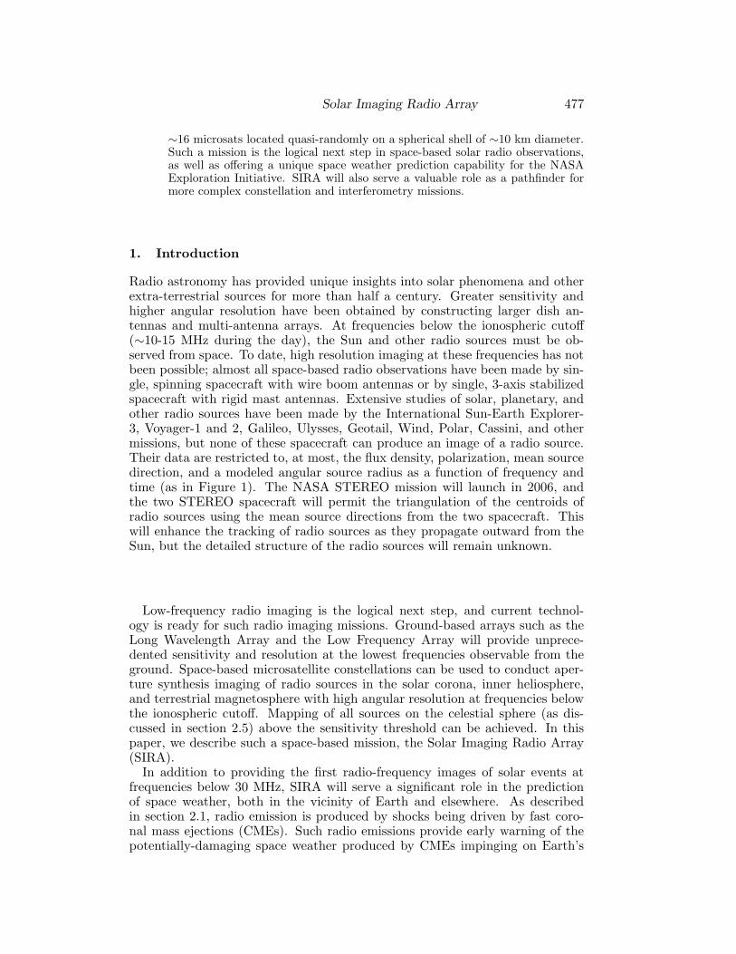
486 MacDowall et al.
Aperture synthesis imaging of very wide fields requires 3-D Fourier transforms,but regions of limited angular size (over which the effects of sky curvature aresmall) can be imaged with separate transforms in which one dimension is muchsmaller than the other two (Cornwall and Perley, 1992; Linfield, 1996). Thisapproach lends itself to parallel processing. For the SIRA mission, the imagingproblem is most difficult at the highest frequency (15 MHz) where the synthe-sized beam is smallest (∼4 arcmin). We plan to make 1024 x 1024 pixel imageswith 50 arcsec pixels, so each image will cover an area of 14◦ x 14◦. Thus,∼200 images are needed to cover the entire sky. Each image will require a 16pixel Fourier transform in the radial direction to allow for sky curvature overthe largest scale structure to which the data are sensitive. Each image will bedivided into ∼100 smaller areas which will each be deconvolved with the ap-propriate synthesized or dirty beam. All clean components are subtracted fromthe data for each field and each field is transformed again to produce resid-ual images. This continues until no sidelobes remain. For intense solar bursts,snapshot images will be obtained without iterative processing.
5. Role of SIRA as a Technology Pathfinder
Of the many space missions being proposed with more than a dozen satellites,SIRA is among the easiest and least expensive to develop. The radio receiversare simple, light weight, low power, low cost instruments that do not constrainthe microsats. The mission takes place in the moderate radiation environmentof space beyond the magnetosphere. Requirements for spacecraft pointing andconstellation control are easily met. Consequently, SIRA represents the opportu-nity to implement a constellation with a dozen or more spacecraft on a MIDEXbudget.
SIRA is also a pathfinder for space-based interferometry. Because the missionobserves at the longest wavelengths of the electromagnetic spectrum propagat-ing in near-Earth space, all aspects of interferometric design become easier. Theinter-microsat ranging accuracy requirement is 3 m. The required constellationbaselines are sufficiently long that there is no need for autonomous formation fly-ing: spacecraft separations can be telemetered to the ground, where the neededmaneuvers are determined and uplinked to the microsats. Nevertheless, the mis-sion operations for SIRA would exercise all of the required functions relevant toa more demanding, shorter wavelength interferometric array in space.
With the conclusion of a successful SIRA mission, it would be appropriateto consider more advanced radio imaging missions. One possibility would bea SIRA Stereo mission, where two SIRA constellations would be inserted intoseparate orbits with one in an L1 halo or distant retrograde orbit around Earth,and the other in a heliocentric 1 AU orbit, gradually drifting away from Earth.The combined images from the two constellations would permit stereo viewingof the radio emissions in the interplanetary medium.
The ultimate goal for low-frequency radio astronomy is to operate radio ob-servatories on the moon, including a far-side observatory that would be per-manently shielded from natural and man-made terrestrial radio noise. Fixingvery large number of antennas on the lunar surface provides high sensitivityand angular resolution. We envision a system where ∼10,000 dipole anten-
Solar Imaging Radio Array 487
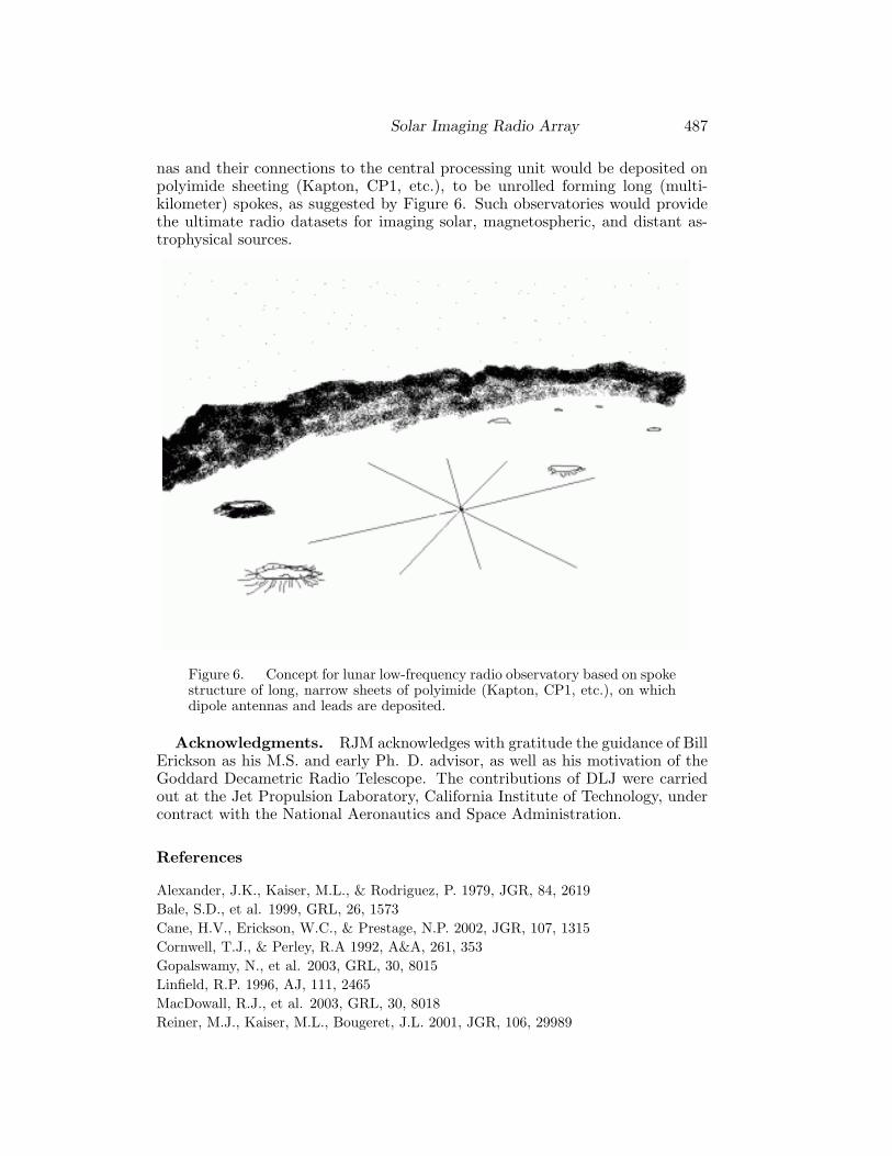
nas and their connections to the central processing unit would be deposited onpolyimide sheeting (Kapton, CP1, etc.), to be unrolled forming long (multi-kilometer) spokes, as suggested by Figure 6. Such observatories would providethe ultimate radio datasets for imaging solar, magnetospheric, and distant as-trophysical sources.
Figure 6. Concept for lunar low-frequency radio observatory based on spokestructure of long, narrow sheets of polyimide (Kapton, CP1, etc.), on whichdipole antennas and leads are deposited.
Acknowledgments. RJM acknowledges with gratitude the guidance of BillErickson as his M.S. and early Ph. D. advisor, as well as his motivation of theGoddard Decametric Radio Telescope. The contributions of DLJ were carriedout at the Jet Propulsion Laboratory, California Institute of Technology, undercontract with the National Aeronautics and Space Administration.
References
Alexander, J.K., Kaiser, M.L., & Rodriguez, P. 1979, JGR, 84, 2619
Bale, S.D., et al. 1999, GRL, 26, 1573
Cane, H.V., Erickson, W.C., & Prestage, N.P. 2002, JGR, 107, 1315
Cornwell, T.J., & Perley, R.A 1992, A&A, 261, 353
Gopalswamy, N., et al. 2003, GRL, 30, 8015
Linfield, R.P. 1996, AJ, 111, 2465
MacDowall, R.J., et al. 2003, GRL, 30, 8018
Reiner, M.J., Kaiser, M.L., Bougeret, J.L. 2001, JGR, 106, 29989


![Outline ■The Heliosphere, Astrospheres and the Interstellar Interaction ● Implications of Recent Voyager Results ■Energetic Neutral Atoms [ENAs], ENA Imaging](https://img.dokumen.tips/doc/110x75/5697c0021a28abf838cc329b/outline-the-heliosphere-astrospheres-and-the-interstellar-interaction-.jpg)