Embed Size (px)
Citation preview
A DESIGNERS' HANDBOOK SERIES No 9029
Distributed by the Nickel Development Institute
Produced by the
AMERICAN IRON AND STEEL INSTITUTE
THE ROLE OF STAINLESS STEELS IN DESALINATION
NiDl
INTRODUCTION
There are several characteristics of the family of corrosion-resistant steels known as stainless steels that make them highly desirable and eminently qualified for desalination service, not only for piping applications but for all desalting plant systems. In. considering the applicability of stainless steels for desalination, the following factors are especially pertinent:
1. Some stainless steels have performed well in desalting environments.
2. Stainless steel tubing has good in-service heat transfer
characteristics. 3. In comparison to other desalination plant materials, such as
titanium, stainless steels are preferable from the economic standpoint.
4. Most stainless steel types that are suitable for desalting
service are readily available. 5. Stainless steels in general are easily fabricated, and there
are many knowledgeable stainless equipment manufacturers in the United States and Canada.
Acceptance of stainless steels for desalination service, however, has been limited primarily because of a paucity of long-term experience in full-size plants. This is no longer the case because data currently available from full-size plants around the world, from OSW test bed plants, and from evaluations conducted at the OSW Materials Test Center in Freeport, Texas, suggest that stainless steels could very well minimize or eliminate completely many of the materials-related problems plaguing plants today.
Cover: Partial flow diagram of the 3000-GPD Stainless Steel Desalination Test Plant that operated for three years at the OSW Materials Test Center in Freeport, Texas.
1
CONTENTS
PERFORMANCE OF STAINLESS STEELS IN FULL-SIZE DESALINATION PLANTS ......................................................... 2
Caspian Sea .................................................................................................. 2
1-MGD Plant in Freeport, Texas ....................................................................... 2 Water Box Liners Distributor Plates Wire Screens Piping & Pumps Weirs Heat Exchange Tubing
World-Wide Surveys ...................................................................................... 5 Intake Screens Mist Eliminators Water Boxes Pumps Flash Chambers
New Plant Construction ................................................................................. 7 Virgin Islands Delta Queen 11,500-GPD VTE Test Plant
EVALUATION OF STAINLESS STEELS IN 3000-GPD DESALINATION TEST PLANT ....................................................... 9
Plant Process Equipment ................................................................................ 12 Pipe Vessels Flanges Pumps Valves
Heat Exchange Tubing .................................................................................... 15
HEAT TRANSFER QUALITIES OF STAINLESS STEEL TUBING .................... 16 Enhanced Tubing
STAINLESS STEEL TYPES ............................................................................ 20
STAINLESS STEEL MILL FORMS .................................................................. 20 Sheet and Strip Tubing Coils Wire Plate Structural & Special Shapes Bar Extrusions
FINISHES AND TEXTURES ............................................................................. 24
Standard Sheet Finishes ........................................................................... 24 Rolled Finishes Polished Finishes
Standard Strip Finishes ............................................................................. 25
Standard Plate Finishes ............................................................................ 25
Refinishing and Blending ........................................................................... 25
Textured Patterns & Other Finishes ............................................................. 25
TIPS ON FABRICATING STAINLESS STEELS ............................................... 25 Forming Welding Cutting Fasteners
TIPS ON DESIGNING WITH STAINLESS STEELS .......................................... 29
TIPS ON GETTING THE MOST BENEFIT FROM STAINLESS STEELS IN DESALINATION ....................................................... 29 Welding Operation Cleaning
CONCLUSION ................................................................................................. 31
REFERENCES ................................................................................................. 32
2
PERFORMANCE OF STAINLESS STEELS IN FULL-SIZE DESALINATION PLANTS
Caspian Sea
One of the earliest reports of stainless steels used in desalination was in a 1.5-MGD plant on the Caspian Sea. Russian engineers related their experiences in 1965 (1, 2) with AISI 300 series stainless steels for heat exchanger tubing, evaporator shells, and process piping in both an experimental as well as a full-size industrial multi-effect long tube vertical (LTV) plant.
In the experimental plant, pitting attack on the evaporator tubes was noted in the first effect, but no pitting was evident in subsequent effects. The authors attributed the lack of pitting in the later effects to the complete removal of dissolved oxygen from the sea water upon boiling in the first effect. Type 316 (titanium-stabilized) was used for evaporator tubes in the industrial plant, and after 1.5 years of service, no signs of pitting were observed.
1-MGD Plant in Freeport, Texas
The Office of Saline Water (OSW) 1-MGD LTV Test Bed Desalination Plant in Freeport, Texas, was built in 1961. It consisted of 12 effects to which a five-effect module was added in 1967. Then in 1971, the plant was virtually rebuilt from the ground up as a combined vertical tube evaporator (VTE) and multistage flash evaporator (MSF). It used the five-effect module and many components from the original plant.
Some of the equipment in the new modified plant as well as in the original VTE unit was fabricated of stainless steel including evaporator tubing, water box liners, pumps, piping, weirs, screens, distributor plates and miscellaneous parts. Examinations of these components conducted during various shutdowns of the plant showed the stainless steels to be standing up well to the hot brine conditions.
Investigations in 1967 and 1968 by Jones and others (3, 4) showed encouraging results in the low-oxygen environment. It appeared (at that time) that Types 304 and 316 stainless steels would be suitable for heat transfer tubes in equipment handling sea water and concentrated brine from which no solid products will deposit, and which has been completely deaerated by previous boiling. (Later data showed Type 304 to be inadequate for desalination heat exchange service.)
In addition to tubing data, Jones also reported excellent performance with Type 316L stainless steel water box liners and baffle plates.
3
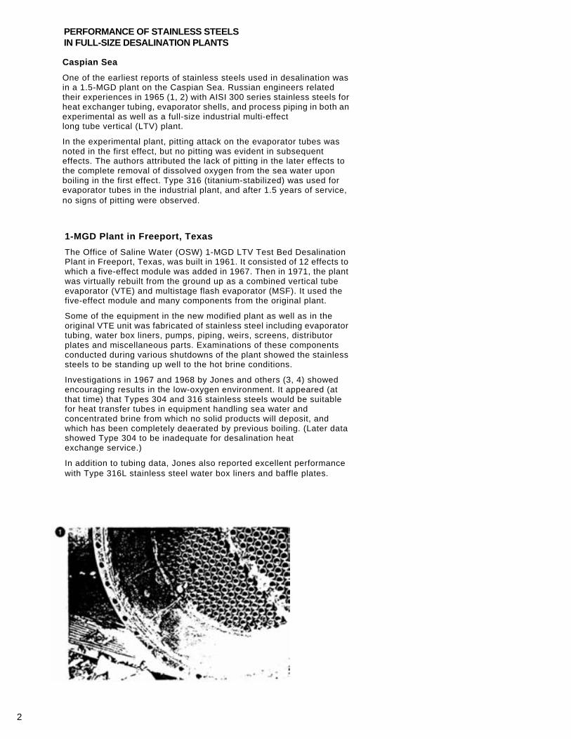
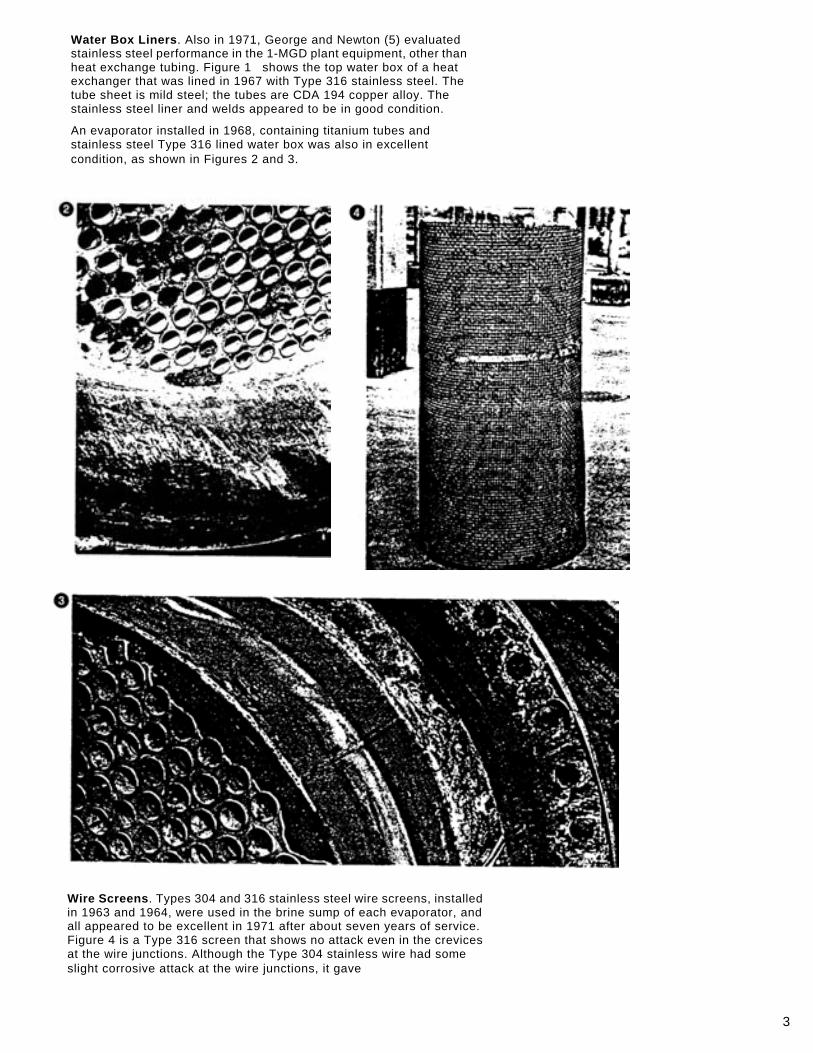
Water Box Liners. Also in 1971, George and Newton (5) evaluated stainless steel performance in the 1-MGD plant equipment, other than heat exchange tubing. Figure 1 shows the top water box of a heat exchanger that was lined in 1967 with Type 316 stainless steel. The tube sheet is mild steel; the tubes are CDA 194 copper alloy. The stainless steel liner and welds appeared to be in good condition.
An evaporator installed in 1968, containing titanium tubes and stainless steel Type 316 lined water box was also in excellent condition, as shown in Figures 2 and 3.
Wire Screens. Types 304 and 316 stainless steel wire screens, installed in 1963 and 1964, were used in the brine sump of each evaporator, and all appeared to be excellent in 1971 after about seven years of service. Figure 4 is a Type 316 screen that shows no attack even in the crevices at the wire junctions. Although the Type 304 stainless wire had some slight corrosive attack at the wire junctions, it gave
4
entirely satisfactory service. The mild steel pipe to which it was attached was slightly corroded, and no doubt it gave some cathodic protection to the screen.
Weirs. The Types 304 and 316 stainless steel weirs used in the original plant were all in excellent condition and subsequently installed in the modified plant.
Distributor Plates. A few very shallow pits (five mils in ¼ inch plate) were found on the flow distribution plates in the evaporator water boxes. The stainless steel was a replacement for Transite, which had become brittle .
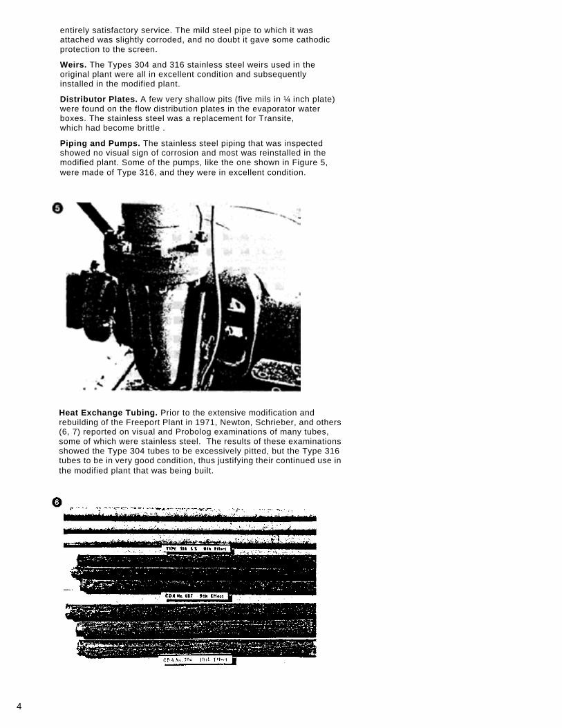
Piping and Pumps. The stainless steel piping that was inspected showed no visual sign of corrosion and most was reinstalled in the modified plant. Some of the pumps, like the one shown in Figure 5, were made of Type 316, and they were in excellent condition.
Heat Exchange Tubing. Prior to the extensive modification and rebuilding of the Freeport Plant in 1971, Newton, Schrieber, and others (6, 7) reported on visual and Probolog examinations of many tubes, some of which were stainless steel. The results of these examinations showed the Type 304 tubes to be excessively pitted, but the Type 316 tubes to be in very good condition, thus justifying their continued use in the modified plant that was being built.
5
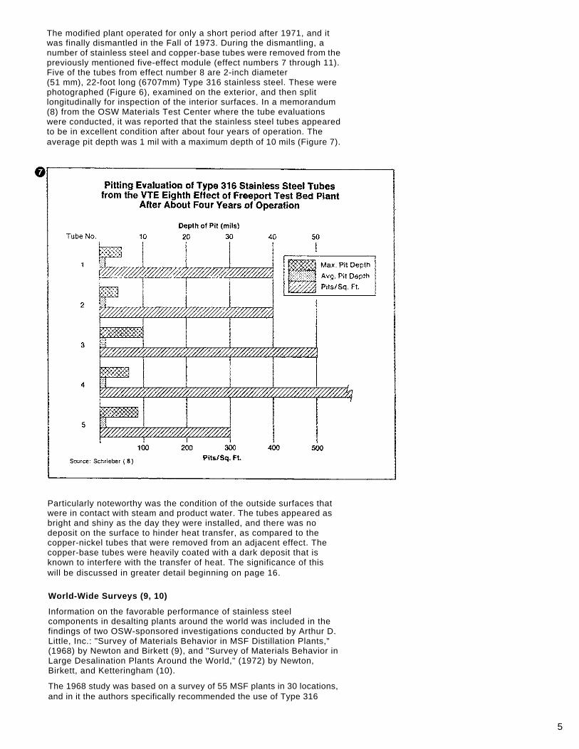
The modified plant operated for only a short period after 1971, and it was finally dismantled in the Fall of 1973. During the dismantling, a number of stainless steel and copper-base tubes were removed from the previously mentioned five-effect module (effect numbers 7 through 11). Five of the tubes from effect number 8 are 2-inch diameter (51 mm), 22-foot long (6707mm) Type 316 stainless steel. These were photographed (Figure 6), examined on the exterior, and then split longitudinally for inspection of the interior surfaces. In a memorandum (8) from the OSW Materials Test Center where the tube evaluations were conducted, it was reported that the stainless steel tubes appeared to be in excellent condition after about four years of operation. The average pit depth was 1 mil with a maximum depth of 10 mils (Figure 7).
Particularly noteworthy was the condition of the outside surfaces that were in contact with steam and product water. The tubes appeared as bright and shiny as the day they were installed, and there was no deposit on the surface to hinder heat transfer, as compared to the copper-nickel tubes that were removed from an adjacent effect. The copper-base tubes were heavily coated with a dark deposit that is known to interfere with the transfer of heat. The significance of this will be discussed in greater detail beginning on page 16.
World-Wide Surveys (9, 10)
Information on the favorable performance of stainless steel components in desalting plants around the world was included in the findings of two OSW-sponsored investigations conducted by Arthur D. Little, Inc.: "Survey of Materials Behavior in MSF Distillation Plants," (1968) by Newton and Birkett (9), and "Survey of Materials Behavior in Large Desalination Plants Around the World," (1972) by Newton, Birkett, and Ketteringham (10).
The 1968 study was based on a survey of 55 MSF plants in 30 locations, and in it the authors specifically recommended the use of Type 316

6
stainless steel for pump parts, particularly impellers, and for water box liners. Five of the units surveyed had stainless steel demisters.
In the 1972 survey, 123 plants responded, and a summary of the stainless steel applications is as follows:
Intake Screens. Most desalting plants use either moving or fixed screens, or a combination of the two, to remove debris from the feedwater. In 64 plants, stainless steel was the material used for intake screen construction.
Water Boxes. Corrosion of water boxes is one of the more serious maintenance problems in desalting plants. Many plants experienced extensive pitting, general corrosion, graphitization of cast iron, and problems in maintaining protective coatings exposed to high-velocity hot brine. Considerable relief from corrosion was provided by lining the water boxes with a corrosion-resistant alloy, such as stainless steel.
For example, the 2.62-MGD plant in Key West, Florida, which started operations in 1967, reports that severely corroded steel water boxes are now lined with Type 316 stainless. In Guantanamo Bay, Cuba, where two small desalting units went into operation in 1964, engineers replaced copper-nickel water boxes in the reject section with stainless steel. And, at a plant in St. Thomas, Virgin Islands, similar difficulties with water box corrosion are being resolved with stainless steel liners.
Flash Chambers. The corrosion of steel flash chambers and associated equipment is one of the chief reasons for loss of production, high maintenance, and increased operating costs in MSF plants. Most extensive pitting is reported in fairly new plants using acid-treated feedwater and operating at high brine temperatures (near 250°F or 121 °C).
In most plants replying to the survey of 1972, flash chambers are constructed of mild steel. About half are uncoated and account for much of the corrosion damage, while other units employ one of several types of coatings. One plant reported to have severe pitting after only a few months of operation, while many other units reported to have badly pitted flash chambers after longer service.
A facility in Key West is one that lined flash chambers with stainless steel in areas of brine impingement. Two 3.75-MGD units in Rosarito, Mexico, which experienced severe pitting of carbon steel (up to 200 mils), applied Type 316 stainless steel liners to prevent further deterioration. Two small plants in the Virgin Islands and others throughout the world reported similar experiences. One plant in Kuwait provided information about corroded steel hoods, brine gates and lever mechanisms, and bolts that were replaced with stainless steel.
In eight other plants using acid-treated sea water, the hottest stage (No. 1) was lined with stainless steel and in four other plants from six to nine of the hotter stages were similarly lined. The lining of the hotter stages was often carried out after the unit had experienced considerable corrosion. As a result of these experiences, some manufacturers now use stainless steel in constructing new flash chamber components.
Also in flash chambers, many of the brine nozzles are of stainless steel.
Mist Eliminators. Many desalination plants use nickel-copper alloy or stainless steel Types 304 or 316 wire mesh for mist eliminators. While no corrosion problems are apparent in the stainless steel mesh, five
7
plants reported to have excessive corrosion of the nickel-copper units and replaced them with stainless. Corrosion by sulfides in the reject stage seems to be the usual mode of attack.
Pumps. As noted in the surveys (9, 10), the choice of materials for pumps depends on service. The choice is dictated by first costs, service life and replacement costs. Thus, even though stainless steel impellers may be more expensive, their long life in sea water service provides better cost effectiveness than the less-resistant bronze impellers.
Out of 331 feedwater, recirculation, or product-water pump impellers listed in the survey (10), about half are of AlSl 300 series stainless steel and half of bronze. The largest number of failures, however, occurred with bronze.
Casings, on the other hand, are not subject to as severe cavitation erosion and corrosion conditions as the impellers, so there is less dependence on stainless steel. Nevertheless, of the 354 pump casings listed in the survey, 38 had erosion/corrosion problems, and these were units made of cast iron, Ni-resist, bronze, and cast steel. No problems were reported with stainless steel casings, which were made either of Types 304, 316, or 317.
Trouble with pump shafts is quite minor among the plants reporting to the survey, with only 12 instances of shaft failures noted. Most shafts for pumps in all types of desalting service are of Types 303, 304, or 316.
New Plant Construction
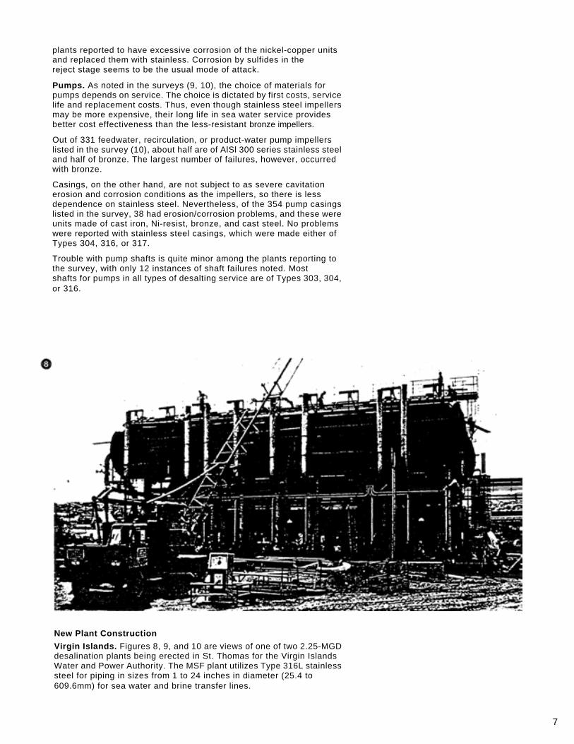
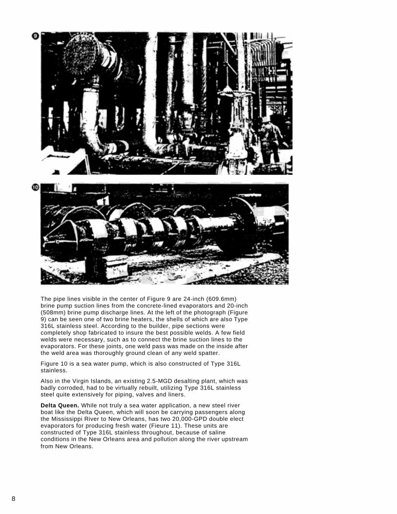
Virgin Islands. Figures 8, 9, and 10 are views of one of two 2.25-MGD desalination plants being erected in St. Thomas for the Virgin Islands Water and Power Authority. The MSF plant utilizes Type 316L stainless steel for piping in sizes from 1 to 24 inches in diameter (25.4 to 609.6mm) for sea water and brine transfer lines.
8
The pipe lines visible in the center of Figure 9 are 24-inch (609.6mm) brine pump suction lines from the concrete-lined evaporators and 20-inch (508mm) brine pump discharge lines. At the left of the photograph (Figure 9) can be seen one of two brine heaters, the shells of which are also Type 316L stainless steel. According to the builder, pipe sections were completely shop fabricated to insure the best possible welds. A few field welds were necessary, such as to connect the brine suction lines to the evaporators. For these joints, one weld pass was made on the inside after the weld area was thoroughly ground clean of any weld spatter.
Figure 10 is a sea water pump, which is also constructed of Type 316L stainless.
Also in the Virgin Islands, an existing 2.5-MGD desalting plant, which was badly corroded, had to be virtually rebuilt, utilizing Type 316L stainless steel quite extensively for piping, valves and liners.
Delta Queen. While not truly a sea water application, a new steel river boat like the Delta Queen, which will soon be carrying passengers along the Mississippi River to New Orleans, has two 20,000-GPD double elect evaporators for producing fresh water (Fieure 11). These units are constructed of Type 316L stainless throughout, because of saline conditions in the New Orleans area and pollution along the river upstream from New Orleans.
9
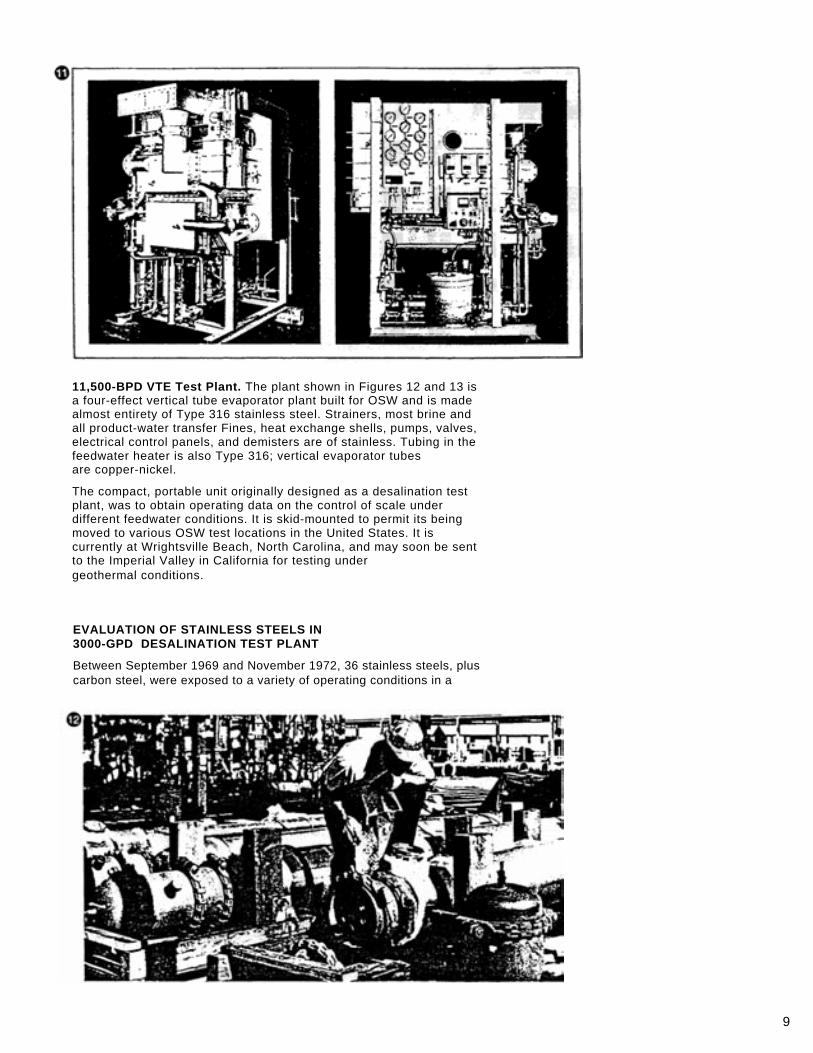
11,500-BPD VTE Test Plant. The plant shown in Figures 12 and 13 is a four-effect vertical tube evaporator plant built for OSW and is made almost entirety of Type 316 stainless steel. Strainers, most brine and all product-water transfer Fines, heat exchange shells, pumps, valves, electrical control panels, and demisters are of stainless. Tubing in the feedwater heater is also Type 316; vertical evaporator tubes are copper-nickel.
The compact, portable unit originally designed as a desalination test plant, was to obtain operating data on the control of scale under different feedwater conditions. It is skid-mounted to permit its being moved to various OSW test locations in the United States. It is currently at Wrightsville Beach, North Carolina, and may soon be sent to the Imperial Valley in California for testing under geothermal conditions.
EVALUATION OF STAINLESS STEELS IN 3000-GPD DESALINATION TEST PLANT
Between September 1969 and November 1972, 36 stainless steels, plus carbon steel, were exposed to a variety of operating conditions in a
10
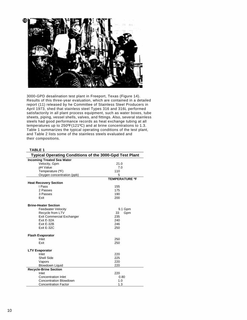
3000-GPD desalination test plant in Freeport, Texas (Figure 14). Results of this three-year evaluation, which are contained in a detailed report (11) released by he Committee of Stainless Steel Producers in April 1973, shed that stainless steel Types 316 and 316L performed satisfactorily in all plant process equipment, such as water boxes, tube sheets, piping, vessel shells, valves, and fittings. Also, several stainless steels had good performance records as heat exchange tubing at all temperatures up to 250ºF(121ºC) and at brine concentrations to 1.3. Table 1 summarizes the typical operating conditions of the test plant, and Table 2 lists some of the stainless steels evaluated and their compositions.
TABLE 1
Typical Operating Conditions of the 3000-Gpd Test Plant Incoming Treated Sea Water
Velocity, Gpm 21.0 pH Value 7.0 Temperature (ºF) 110 Oxygen concentration (ppb) 5
TEMPERATURE ºF Heat Recovery Section
I Pass 155 2 Passes 175 3 Passes 190 Exit 200
Brine-Heater Section
Feedwater Velocity 9.1 Gpm Recycle from LTV 33 Gpm Exit Commercial Exchanger 235 Exit E-32A 240 Exit E-32B 246 Exit E-32C 250
Flash Evaporator
Inlet 250 Exit 250
LTV Evaporator
Inlet 220 Shell Side 225 Vapors 220 Blowdown Liquid 220
Recycle-Brine Section Inlet 220 Concentration Inlet 0.80 Concentration Blowdown 1.0 Concentration Factor 1.3
11
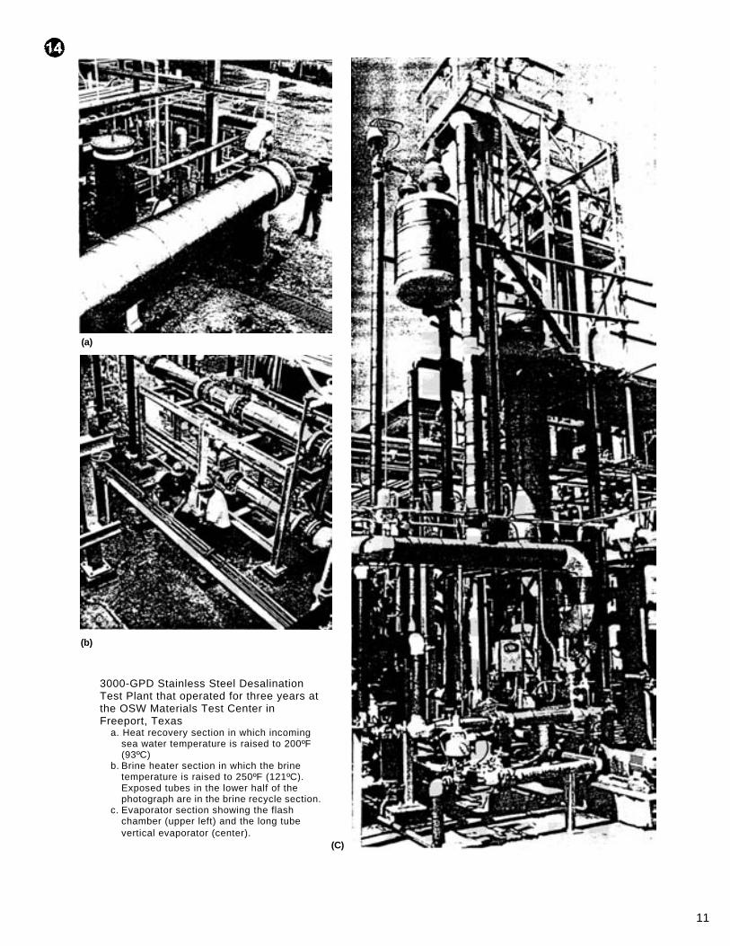
3000-GPD Stainless Steel Desalination Test Plant that operated for three years at the OSW Materials Test Center in Freeport, Texas
a. Heat recovery section in which incoming sea water temperature is raised to 200ºF (93ºC)
b. Brine heater section in which the brine temperature is raised to 250ºF (121ºC). Exposed tubes in the lower half of the photograph are in the brine recycle section.
c. Evaporator section showing the flash chamber (upper left) and the long tube vertical evaporator (center).
(C)
(a)
(b)
12
TABLE 2
Some of the Stainless Steels Evaluated in the 3000-GPD Desalination Test Plant
Alloy %C %Mn %Cr %Ni %Mo Other (Standard AISI Stainless Steels–Chemical Composition)
304 0.08 Max 2.00 Max 18.00/ 20.00
8.00/ 10.00
309 0.20 Max 2.00 Max 22.00/ 24.00
12.00/ 15.00
316 0.08 Max 2.00 Max 16.00/ 18.00
10.00/ 14.00
2.00/ 3.00
316L 0.03 Max 2.00 Max 16.00/ 18.00
10.00/ 14.00
2.00/ 3.00
317 0.08 Max 2.00 Max 18.00/ 20.00
11.00/ 15.00
3.00/ 4.00
(Other Stainless Steels–Certified Chemical Analyses) 216 0.045 8.40 19.70 7.10 2.83 N 0.35 304N 0.03 1.64 19.29 8.15 0.26 N 0.253 329 0.06 0.38 27.51 4.25 1.55 26-1 0.0015 0.01 26.73 0.13 0.90 N 0.011
20-Cb 3 0.03 0.23 19.67 33.87 2.26 Cu 3.36;
Cb+Ta 0.82
22-13-5 0.05 5.44 21.48 12.36 2.12 V 0.20; N 0.27; Cb+Ta 0.19
20-45-5 0.060 5.21 19.45 44.14 2.22 Cb+Ta 0.15
6X 0.038 1.73 20.41 23.61 6.50
800 0.030 1.01 20.85 32.05
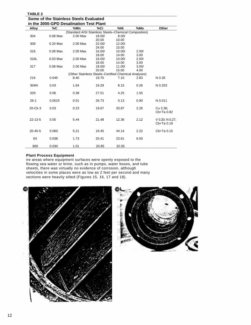
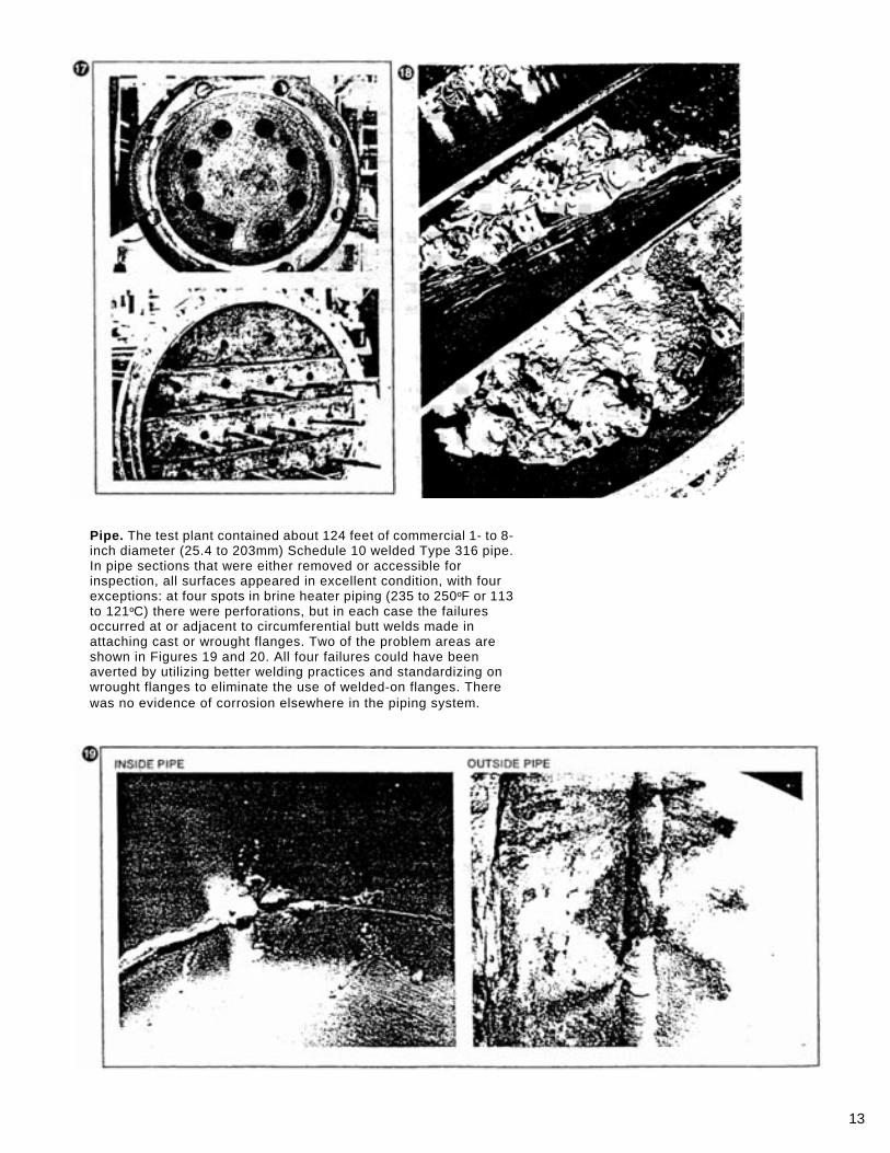
Plant Process Equipment ire areas where equipment surfaces were openly exposed to the flowing sea water or brine, such as in pumps, water boxes, and tube sheets, there was virtually no evidence of corrosion, although velocities in some places were as low as 2 feet per second and many sections were heavily silted (Figures 15, 16, 17 and 18).
13
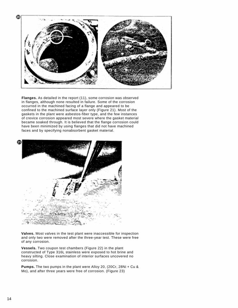
Pipe. The test plant contained about 124 feet of commercial 1- to 8-inch diameter (25.4 to 203mm) Schedule 10 welded Type 316 pipe. In pipe sections that were either removed or accessible for inspection, all surfaces appeared in excellent condition, with four exceptions: at four spots in brine heater piping (235 to 250ºF or 113 to 121ºC) there were perforations, but in each case the failures occurred at or adjacent to circumferential butt welds made in attaching cast or wrought flanges. Two of the problem areas are shown in Figures 19 and 20. All four failures could have been averted by utilizing better welding practices and standardizing on wrought flanges to eliminate the use of welded-on flanges. There was no evidence of corrosion elsewhere in the piping system.
14
Flanges. As detailed in the report (11), some corrosion was observed in flanges, although none resulted in failure. Some of the corrosion occurred in the machined facing of a flange and appeared to be confined to the machined surface layer only (Figure 21). Most of the gaskets in the plant were asbestos-fiber type, and the few instances of crevice corrosion appeared most severe where the gasket material became soaked through. It is believed that the flange corrosion could have been minimized by using flanges that did not have machined faces and by specifying nonabsorbent gasket material.
Valves. Most valves in the test plant were inaccessible for inspection and only two were removed after the three-year test. These were free of any corrosion.
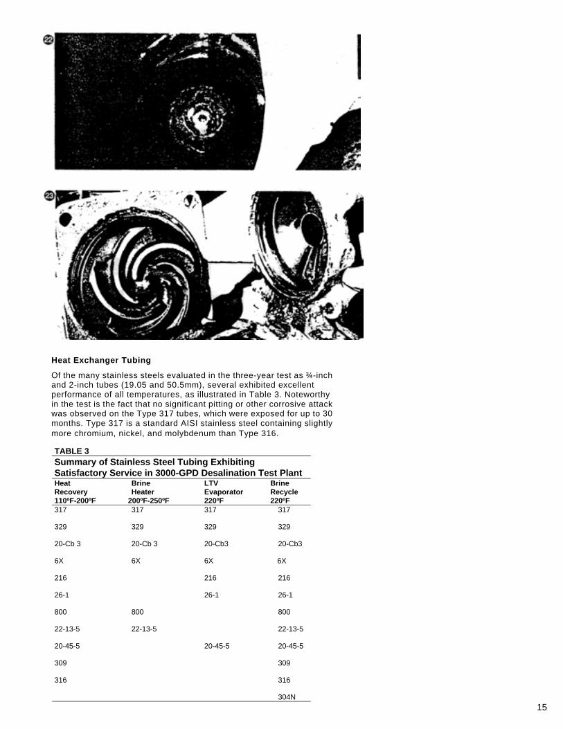
Vessels. Two coupon test chambers (Figure 22) in the plant constructed of Type 316L stainless were exposed to hot brine and heavy silting. Close examination of interior surfaces uncovered no corrosion.
Pumps. The two pumps in the plant were Alloy 20, (20Cr, 28Ni + Cu & Mo), and after three years were free of corrosion. (Figure 23)
15
Heat Exchanger Tubing
Of the many stainless steels evaluated in the three-year test as ¾-inch and 2-inch tubes (19.05 and 50.5mm), several exhibited excellent performance of all temperatures, as illustrated in Table 3. Noteworthy in the test is the fact that no significant pitting or other corrosive attack was observed on the Type 317 tubes, which were exposed for up to 30 months. Type 317 is a standard AISI stainless steel containing slightly more chromium, nickel, and molybdenum than Type 316.
TABLE 3
Summary of Stainless Steel Tubing Exhibiting Satisfactory Service in 3000-GPD Desalination Test Plant Heat Recovery 110ºF-200ºF
Brine Heater
200ºF-250ºF
LTV Evaporator 220ºF
Brine Recycle 220ºF
317 317 317 317 329 329 329 329 20-Cb 3 20-Cb 3 20-Cb3 20-Cb3 6X 6X 6X 6X 216 216 216 26-1 26-1 26-1 800 800 800 22-13-5 22-13-5 22-13-5 20-45-5 20-45-5 20-45-5 309 309 316 316 304N
16
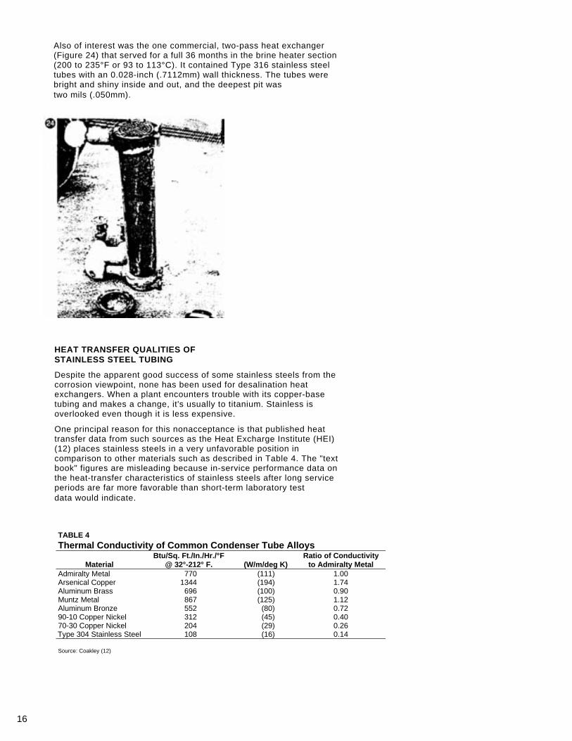
Also of interest was the one commercial, two-pass heat exchanger (Figure 24) that served for a full 36 months in the brine heater section (200 to 235°F or 93 to 113°C). It contained Type 316 stainless steel tubes with an 0.028-inch (.7112mm) wall thickness. The tubes were bright and shiny inside and out, and the deepest pit was two mils (.050mm).
HEAT TRANSFER QUALITIES OF STAINLESS STEEL TUBING
Despite the apparent good success of some stainless steels from the corrosion viewpoint, none has been used for desalination heat exchangers. When a plant encounters trouble with its copper-base tubing and makes a change, it's usually to titanium. Stainless is overlooked even though it is less expensive.
One principal reason for this nonacceptance is that published heat transfer data from such sources as the Heat Excharge Institute (HEI) (12) places stainless steels in a very unfavorable position in comparison to other materials such as described in Table 4. The "text book" figures are misleading because in-service performance data on the heat-transfer characteristics of stainless steels after long service periods are far more favorable than short-term laboratory test data would indicate.
TABLE 4 Thermal Conductivity of Common Condenser Tube Alloys
Material Btu/Sq. Ft./In./Hr./°F
@ 32°-212° F. (W/m/deg K) Ratio of Conductivity
to Admiralty Metal Admiralty Metal 770 (111) 1.00 Arsenical Copper 1344 (194) 1.74 Aluminum Brass 696 (100) 0.90 Muntz Metal 867 (125) 1.12 Aluminum Bronze 552 (80) 0.72 90-10 Copper Nickel 312 (45) 0.40 70-30 Copper Nickel 204 (29) 0.26 Type 304 Stainless Steel 108 (16) 0.14 Source: Coakley (12)
17
The growing acceptance of stainless steels is indicated by the fact that prior to 1958, a mere one percent of the tubing used in surface condensers was stainless, mostly in areas of steam impingement and in deaeration zones. Today, however, more than 50 percent of the tubes being installed in surface condensers is stainless, and the market continues to grow. One power utility recently placed an order for 30-million feet of stainless steel tubing.
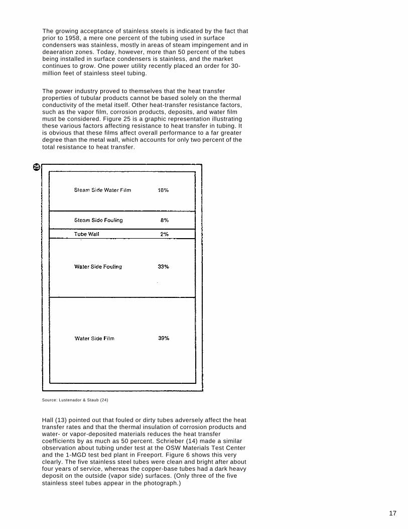
The power industry proved to themselves that the heat transfer properties of tubular products cannot be based solely on the thermal conductivity of the metal itself. Other heat-transfer resistance factors, such as the vapor film, corrosion products, deposits, and water film must be considered. Figure 25 is a graphic representation illustrating these various factors affecting resistance to heat transfer in tubing. It is obvious that these films affect overall performance to a far greater degree than the metal wall, which accounts for only two percent of the total resistance to heat transfer.
Source: Lustenador & Staub (24)
Hall (13) pointed out that fouled or dirty tubes adversely affect the heat transfer rates and that the thermal insulation of corrosion products and water- or vapor-deposited materials reduces the heat transfer coefficients by as much as 50 percent. Schrieber (14) made a similar observation about tubing under test at the OSW Materials Test Center and the 1-MGD test bed plant in Freeport. Figure 6 shows this very clearly. The five stainless steel tubes were clean and bright after about four years of service, whereas the copper-base tubes had a dark heavy deposit on the outside (vapor side) surfaces. (Only three of the five stainless steel tubes appear in the photograph.)
18
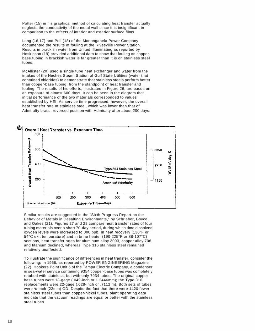
Potter (15) in his graphical method of calculating heat transfer actually neglects the conductivity of the metal wall since it is insignificant in comparison to the effects of interior and exterior surface films. Long (16,17) and Pell (18) of the Monongahela Power Company documented the results of fouling at the Rivesville Power Station. Results in brackish water from United Illuminating as reported by Hoskinson (19) provided additional data to show that fouling on copper-base tubing in brackish water is far greater than it is on stainless steel tubes. McAllister (20) used a single tube heat exchanger and water from the intakes of the Neches Steam Station of Gulf State Utilities (water that contained chlorides) to demonstrate that stainless steels perform better than copper-base tubing, from the standpoint of heat transfer and fouling. The results of his efforts, illustrated in Figure 26, are based on an exposure of almost 600 days. It can be seen in the diagram that initial performance of the two materials corresponded to values established by HEI. As service time progressed, however, the overall heat transfer rate of stainless steel, which was lower than that of Admiralty brass, reversed position with Admiralty after about 200 days.
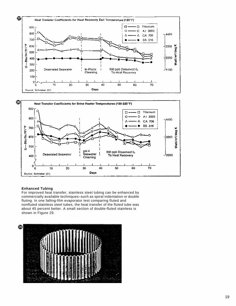
Similar results are suggested in the "Sixth Progress Report on the Behavior of Metals in Desalting Environments," by Schrieber, Boyce, and Oakes (21). Figures 27 and 28 compare heat transfer rates of four tubing materials over a short 70-day period, during which time dissolved oxygen levels were increased to 300 ppb. In heat recovery (130°F or 54°C exit temperature) and in brine heater (190-225°F or 88-107°C) sections, heat transfer rates for aluminum alloy 3003, copper alloy 706, and titanium declined, whereas Type 316 stainless steel remained relatively unaffected. To illustrate the significance of differences in heat transfer, consider the following: In 1968, as reported by POWER ENGINEERING Magazine (22), Hookers Point Unit 5 of the Tampa Electric Company, a condenser in sea-water service containing 9354 copper-base tubes was completely retubed with stainless, but with only 7934 tubes. The original copper-base tubes were 18-gage (.049-inch or 1.2446mm); the Type 316 replacements were 22-gage (.028-inch or .7112 m). Both sets of tubes were 7/8-inch (22mm) OD. Despite the fact that there were 1420 fewer stainless steel tubes than copper-nickel tubes, plant operating data indicate that the vacuum readings are equal or better with the stainless steel tubes.
19
Enhanced Tubing For improved heat transfer, stainless steel tubing can be enhanced by commercially available techniques–such as spiral indentation or double fluting. In one falling-film evaporator test comparing fluted and nonfluted stainless steel tubes, the heat transfer of the fluted tube was about 45 percent better. A small section of double-fluted stainless is shown in Figure 29.
20
STAINLESS STEEL TYPES
American Iron and Steel Institute (AISI) identifies 58 stainless steels as standard compositions. In addition, many special proprietary types are produced, some of which are listed in Table 2.
In all varieties of stainless steel, chromium is the alloying element that gives the metal its corrosion resistance. To be considered stainless, a steel must contain about 10.5 percent chromium and up. Nickel is another important alloying element that improves corrosion resistance ductility, and fabricating characteristics. Molybdenum is also added to some stainless steels to enhance their resistance to corrosion, especially pitting and crevice attack.
Stainless steels are available in many different compositions to meet a wide variety of fabricating and service conditions. It is well to remember, however, that not all stainless steels have a successful performance record in desalination. For instance, of the standard AISI stainless steels evaluated in the 3000-GPD stainless steel desalination test plant, Types 316 and 316L demonstrated good performance for process piping and other components. Type 317 showed no significant pitting or other corrosive attack as heat exchange tubing.
The information following is about stainless steels in general; the mill forms and finishes in which they are available plus some tips on fabricating stainless steels. It can be helpful either as an introduction to the subject for the engineer approaching stainless steels for the first time or as a refresher for those experienced with stainless steel.
STAINLESS STEEL MILL FORMS
Stainless steels are produced in many different forms, or, in the terms of the trade, in many types of mill products. Stainless steels used in desalination are available through steel service centers, which are located in most cities, or the metal may be purchased by the fabricator directly from the mill.
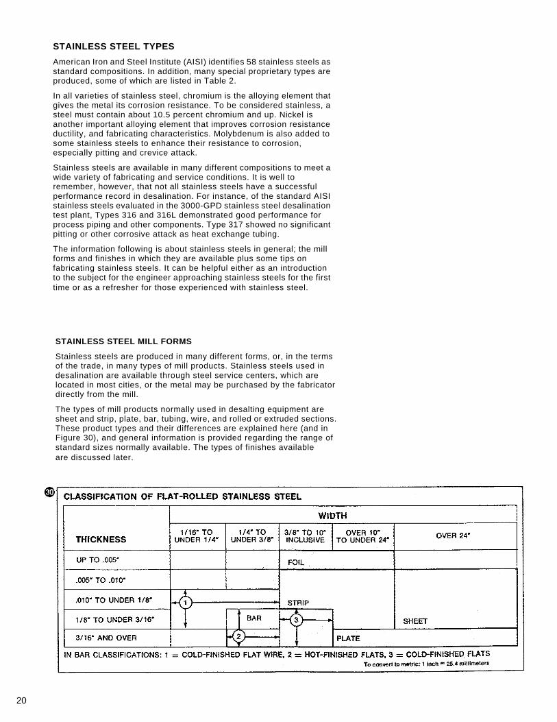
The types of mill products normally used in desalting equipment are sheet and strip, plate, bar, tubing, wire, and rolled or extruded sections. These product types and their differences are explained here (and in Figure 30), and general information is provided regarding the range of standard sizes normally available. The types of finishes available are discussed later.
21
Sheet and Strip
In general, flat-rolled products less than 3/16 inch (4.8mm) thick and more than 3/8 inch (9.5mm) wide are classified as either sheet or strip. If the width is 24 inches (609.6mm) or more, the product is designated as sheet; if less than 24 inches, it is referred to as strip. (See Table 5 for sheet metal gages.)
TABLE 5
THICKNESS IN INCHES (and millimeters) OF SHEET METAL GAGES
Gage Number
U.S. Standard Gage for Stainless Steel
Sheet 8 .17188 (4.36575)
10 .14063 (3.57200) 11 .1250 (3.175) 12 .10938 (2.77825) 14 .07813 (1.98450) 16 .0625 (1.5875) 18 .0500 (1.27) 20 .0375 (.9525) 22 .03125 (.79375) 24 .0250 (.635) 26 .01875 (.47625) 28 .01563 (.39700) 30 .0125 (.3175)
Coils
Both sheet and strip can be furnished in large continuous coils, as well as flat pieces cut to length.
Plate
Flat-rolled products 3/16 inch (4.8mm) or more in thickness and more than 10 inches (254mm) wide are classified as plate. Plates are generally produced by hot rolling followed by annealing and descaling. Certain sizes of lighter-thickness plates can be cold rolled, which produces a smoother finish.
Bar
The product designated bar includes a variety of relatively small shapes: round, square, hexagonal, and octagonal over ¼ inch (6.4mm) in cross-section, and flat bars up to 10 inches (254mm) wide. Smaller sizes (½ inch or 12.7mm and under) technically are classified as wire sizes, but often are listed also as bar sizes. Some of these shapes are hot finished, some cold finished. Hot-finished bar, which may be hot rolled, forged, or extruded, is annealed or heat treated and usually is blast cleaned or descaled. Cold-finished bar is annealed and descaled, then cold rolled and drawn through forming dies.
Cold-finished flats are 1/8 inch (3.2mm) and over in thickness and 3/8 inch (9.5mm) through 10 inches (254mm) in width.
Hot-finished flats have essentially the same thickness range as the cold-finished flats, but a width range from ¼ inch to 10 inches (6.4 to 254mm), inclusive.
Tubing
All products of hollow tubular form, regardless of cross-sectional shape, are designated as either tubing or pipe. These products are produced by both the seamless and the welding processes. Seamless
22
tubular products are manufactured either by rotary piercing or by extrusion from a solid billet. Wedded products are manufactured from flat-rolled strip, sheet, or plate with a longitudinal or spiral seam. (See Table 6 for pipe sizes and weights.)
TABLE 6 PIPE SIZES AND WEIGHTS–TYPES 301, 302, 304, 304L, 309, 310, 316 and 316L. Schedule 5S Schedule 10S Schedule 40S Schedule 80S Nominal
I.P.S. inches
Nominal
O.D. inches
Wall inches
Weight pounds/foot
Wall inches
Weight pounds/foot
Wall inches
Weight pounds/foot
Wall inches
Weight pounds/foot
1/8 0.405 0.049 0.1880 0.068 0.2470 0.095 0.3175 ¼ 0.540 0.065 0.3328 0.088 0.4287 0.119 0.5401 3/8 0.675 0.065 0.4274 0.091 0.5729 0.126 0.7457
½ 0.840 0.065 0.5430 0.083 0.6773 0.109 0.8589 0.147 1.098 ¾ 1.050 0.065 0.6902 0.083 0.8652 0.113 1.141 0.154 1.487
1 1.315 0.065 0.8759 0.109 1.417 0.133 1.695 0.179 2.192 1¼ 1.600 0.065 1.117 0.109 1.822 0.140 2.294 0.191 3.025 1½ 1.900 0.065 1.286 0.109 2.104 0.145 2.743 0.200 3.665 2 2.375 0.065 1.619 0.109 2.662 0.154 3.687 0.218 5.069 2½ 2.875 0.033 2.498 0.120 3.564 0.203 5.847 0.276 7.733 3 3.500 0.083 3.057 0,120 4.372 0.216 7.647 0.300 10.35 3½ 4.000 0.083 3.505 0.120 5.019 0.226 9.194 0.318 12.62 4 4.500 0.083 3.952 0.120 5.666 0.237 10.89 0.337 15.12 5 5.563 0.109 6.409 0.134 7.842 0.258 14.75 0.375 20.97 6 6.625 0.109 7.856 0.134 9.376 0.280 19.15 0.432 28.84 8 8.625 0.109 10.01 0.148 13.52 0.322 28.82 0.500 43.79
10 10.750 0.134 15.34 0.165 18.83 0.365 40.86 0.500 55.25 12 12.750 0.156 21.18 0.180 24.39 0.375 50.03 0.500 66.03 14 14.000 0.156 23.28 0.188 27.99 16 16.000 0.165 28.17 0.188 32.05 18 18.000 0.165 31.72 0.188 36.10 20 20.000 0.188 40.15 0.218 46.49 22 22.000 0.188 44.21 0.218 51.19 24 24.000 0.218 55.89 0.250 64.01 30 30.000 0.250 80.18 0.312 99.85 1 Inch = 25.4mm 1 pound = .4536kg
As pipe, these tubular products are produced in the diameters and schedules associated with carbon steel pipe, plus some extra-light-wall thicknesses. As tubing, the product can be round or in shapes such as square, rectangular, oval, etc. Special shaped tubing is produced in the round form and subsequently shaped by a drawing or forming operation; or formed into the desired shape and then welded.
Stainless tubular products are usually produced in a pickled matte finish, but other finishes are available. As pipe, the product is intended as a conveying line for liquids or gases and is tested to industry specifications. As tubing for pressure use, the material is produced to related industry specifications and is tested accordingly. When used for structural or ornamental applications, it is classified as a mechanical or structural tube and should be so specified.
Stainless tubular products are available in diameters from .010 inch through 40.00 inches (.254 to 1016mm). The maximum diameter for seamless stainless tubular products, however, is 10.75 inches (273.05mm) outside diameter. Wall thickness ranges depend upon the outside diameter. The maximum thickness for welded tubing is considerably less than that for the seamless product.
Wire Cold-finished products one-half inch (12.7mm) and under in their greatest cross-sectional dimension are referred to as wire, and are classified as either round or shaped; the latter classification includes
23
24
square, hexagonal, octagonal, half-round, oval, and other sectional shapes.
Round wire is available in a great many sizes. Shaped wire is produced in fewer standard sizes.
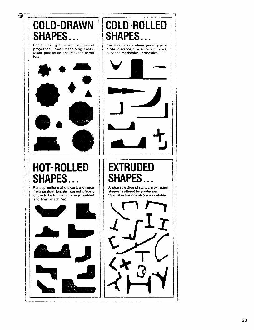
Structural and Special Shapes
Stainless steel angles, channels, tees, I-beams, and H-beams are available. They can be produced by hot rolling, cold rolling, cold drawing, or extruding (Figure 31).
Cold-rolled shapes are made by bending stainless steel strip in a roll-forming machine or by rolling stainless steel bar. Cold-rolled bars are characterized as having close tolerances, fine surface finishes, and superior mechanical properties.
Extrusions
Stainless steel also may be extruded in a great variety of cross-sectional shapes by forcing a heated billet of the metal through hollow dies. This is done under tremendous pressure, using molten glass as a lubricant.
For obvious reasons, this method of forming has been associated with the softer metals. In recent years, however, due to technological advances, the extrusion of steel also has become practical, and this forming process now is being used successfully for both mild and stainless steels. Die costs are low, and relatively short runs are practical.
FINISHES AND TEXTURES
Standard Sheet Finishes
Stainless steel sheet is supplied from the mill in various finishes ranging from completely dull to a full mirror polish. Nine mill finishes are recognized as standard by the American Iron and Steel Institute. In addition, many proprietary finishes are available from individual producers. Some of these are rolled finishes resembling the standard polishes in appearance; others are matte finishes.
Rolled Finishes
No. 1–a dull finish, produced on hand sheet mills by hot rolling, followed by annealing and descaling. It is probably the least expensive of all the finishes and is practical for heavy equipment. Bright Annealed–a bright, highly reflective finish produced by cold rolling and maintained by annealing in a controlled- atmosphere furnace. No. 2D–a dull, nonreflective finish produced by cold rolling, annealing, descaling and a final light skin pass on dull rolls. No. 2B–a bright, moderately reflective finish produced by cold rolling, annealing, descaling, and a final light skin pass on smooth polished rolls.
Polished Finishes
No. 3–an intermediate polished finish, coarser than No. 4, applied with a 100-grit abrasive.
25
No. 4–a bright machine-polished finish with a visible grain that prevents mirror reflection; this is the finish most frequently used for applications in which appearance is important, such as for handrails and architectural trim. A No. 4 polish is applied with a 120-150 grit abrasive. In tubing, this finish is referred to as a 180-grit finish. No. 6–a dull, satin finish produced by Tampico brushing of No. 4 finish sheets with a polishing compound consisting of a light abrasive and oil. No. 7–a bright, highly reflective finish produced by buffing of finely ground surfaces, with grit lines not completely removed. No. 8–a bright mirror finish essentially free of grit lines.
Standard Strip Finishes
Stainless steel strip is supplied in three rolled finishes, plus in those polished finishes described above. No. 1–approximately the same in appearance as sheet finish No. 2D. No. 2–similar in appearance to sheet finish No. 2B. Bright Annealed–similar to bright annealed sheet.
Standard Plate Finishes
Plate is available in the following mill conditions and finishes: hot rolled, annealed and pickled (HRAP); hot rolled, annealed with a shot-blast finish; and hot rolled, annealed with a polished finish.
Refinishing and Blending
For most plant applications, appearance is not important, and once a piece of equipment has been completely fabricated, no effort is made to blend welds and other marks or blemishes on the stainless steel surface. However, if appearance is important, the fabricator may have to refinish areas that were marred during fabrication. Refinishing and blending can be done only with polished finishes; rolled finishes cannot be reproduced by the fabricator.
Textured Patterns and Other Finishes
While of little importance to most plant uses, it is well to know that a variety of other surface treatments can be applied to stainless steel, including painting, shot-blasting, etching, and various textures. The textured or patterned stainless steels tend to conceal scratches, nicks and dents that arise from use in areas of heavy traffic or abuse. Texturing may also increase the stiffness of the stainless sheet, and, in those cases, may permit the use of a thinner gage than otherwise could be used.
TIPS ON FABRICATING STAINLESS STEELS
As the title implies, this section serves to introduce the fabrication characteristics of stainless steels and to illustrate some of the ways in which they differ from other common metals used in process equipment.
In general, stainless steels can be cut, formed, machined, and joined by methods similar to those used for carbon steel. However, because these corrosion-resistant steels have physical properties that differ
26
from carbon steel, slight changes may be necessary in fabricating techniques. It is also important to realize that each individual stainless steel type responds somewhat differently to fabricating operations. When all of these differences are taken into account, stainless steels can be easily and successfully fabricated not only by the big manufacturing shop, but also by the plant maintenance shop as well. To begin with, stainless steels are tough metals; i.e., they have high yield strengths, excellent ductility, and some grades harden during cold working operation, such as bending. Consequently, forming equipment, such as presses, roll-forming machinery, etc., may require more power than normally used with carbon steel. In cutting, tool geometry will be different, tools will have to be kept sharp, and cutting feeds and speeds will be higher. And in welding, lower current settings will be necessary.
Forming
Stainless steels can be successfully drawn, spin formed, roll formed, stretch formed, cold headed, and forged. In most of the cold forming, the higher strength and hardness as compared with carbon steel reflects the need for about twice the power. It is noteworthy, however, that the higher tensile strength of stainless steels permits greater stress before fracturing occurs. On the other hand, the greater hardness causes more rapid wear of the tools and dies.
For desalination process equipment, the first and foremost consideration in selecting a stainless steel is corrosion resistance, and Type 316 is the most widely used. One of the characteristics of Type 316 is work hardening; i.e., as it is cold rolled or formed and shaped into various components, its tensile and yield strengths will increase slightly. Other stainless steels have different work-hardening rates, but these are not considered suitable for desalting service.
The considerations in cold forming Type 316 stainless steel include tool materials and finishes, lubricants, component design, speeds, and the number of forming operations. A complicated part, for instance, might require annealing between operations.
Type 316 can be successfully forged for improved mechanical properties in pumps, valves, and fittings. As with all metals, however, a knowledge of its hot-forming characteristics is helpful to insure a successful operation.
For instance, all stainless steels possess low heat conductivity and are stronger and more resistant to deformation at elevated temperatures than plain carbon steel. Heating must, therefore, be performed more slowly and carefully. On the average, stainless steels require about 25 percent more blows under the hammer than ordinary forging steels. Important considerations include die material, heating and cooling practices. and hammer technique.
Cutting
The machining characteristics of stainless steels are substantially different from those of carbon steel. In varying degree, most stainless steels are tough, rather than hard, and they tend to seize and gall unless proper equipment and practices are employed. There are five good rules to follow: (1) Tools should be kept sharp at all times. (2) Tools should be as large as possible to aid in dissipating heat. (3) Tool holders should be rigid to prevent chatter. (4) Power should be sufficiently high to assure a continuously heavy cut. (5) Feeds and speeds should be generally greater than those for carbon steels.
27
The machinability of some stainless steels has been improved by the addition of small quantities of sulfur or selenium. These additions reduce the friction between the workpiece and the tool, thus minimizing the tendency of the chip to weld to the tool. Also, these additions form inclusions that not only lower the friction forces, but also lower the ductility of the chip causing it to break off more readily.
The addition of sulfur or selenium can adversely affect the corrosion resistance of stainless steels, however, so a free-machining grade should be specified only when machinability is a major factor and corrosion resistance a minor concern, such as in pump shafts for which Type 303 stainless is sometimes specified. It would not be good practice to specify Type 303 for any other parts exposed to brine or product water. Type 316 can be readily machined, but at a slower production rate than Type 303.
Selection of cutting tool material and tool geometry are major factors in successful machining of stainless steels. While regular high-speed tool steels have provided satisfactory service for years, other types have been used with remarkable success, such as cobalt high-speed tools, cemented carbides, and ceramic tools.
In drilling stainless steels, high-speed tool steels should be used. The drills should be ground with a 135°/140° included angle and a 12°to 15° lip clearance, and they should be as short as possible to avoid whipping and possible breakage.
In preparing work for drilling, especially with Type 316 stainless steel that work hardens, a triangular punch will minimize work hardening at the point of the drill start. Rigid support of the work is important, and adequate power and feed will assure continuous cutting so that the drill will not ride the bottom of the hole. If this accidentally occurs, the stainless steel will become work hardened, making it difficult to resume the cutting operation. Chalk applied to the cutting edges of the drill and in the hole will sometimes aid in restarting the cutting in such cases.
Also, cutting fluids are necessary in drilling stainless steels.
To cut stainless, the preferred method is to shear it or cut it with an abrasive cut-off wheel. Hacksaws can be used, however, with best results obtained with high-speed steel blades with a wavy set. For light stock, use fine teeth; coarser teeth give best results with heavy material. With Type 316 stainless steel, cutting should start immediately. If the saw merely slides over the metal surface, local work hardening will result making further cutting very difficult.
Welding
When welding stainless steels, one must recognize that their electrical resistance is about six times greater than carbon steel; their melting point is about 200°F (93°C) lower; and their thermal conductivity is about 50 percent less. The net result of these combined factors means that lower welding current settings are necessary for stainless. Other changes in current settings and polarity may be necessary for better control of the weld arc characteristics. Weld spatter from an unstable arc, for instance, as shown in Figure 19, or incomplete weld penetration can become potential corrosion sites. For welded fabrication; especially when field welding is employed, the low-carbon variation of Type 316, which is Type 316L, would be a better choice.
Most of the stainless steels can be welded by any of the fusion or resistance methods commonly used on carbon steels. Shielded metal-
28
arc welding with coated electrodes predominates in manual operations, but tungsten and consumable electrode joining with gas shielding are also popular. The newer welding processes–plasma arc and electron beam–have been used with good success.
In welding, important considerations include base metal thickness and joint design, current settings, shielding gas, chill bars to dissipate heat, and welding rod selection. Regarding the latter point, welding rod selection is especially important because the weld-deposited metal should have a composition similar to the base metal. For instance, in welding Type 316 stainless, the weld rod should also be Type 316. Many suppliers of welding equipment and welding rods have literature describing welding rod selection and the techniques used to weld stainless steels.
Oxyacetylene is generally not used on stainless steels for welding. Also, cutting stainless with an acetylene torch is difficult unless carbon steel powder is introduced at the torch, or a carbon steel waster plate is placed over the stainless steel to be cut.
Stainless steels can also be brazed or soldered with only minor modification of the technique to accommodate the low thermal conductivity of the metal. And when soldering stainless, a phosphoric acid type flux is preferred. Soldered joints should be thoroughly cleaned after soldering.
Fasteners
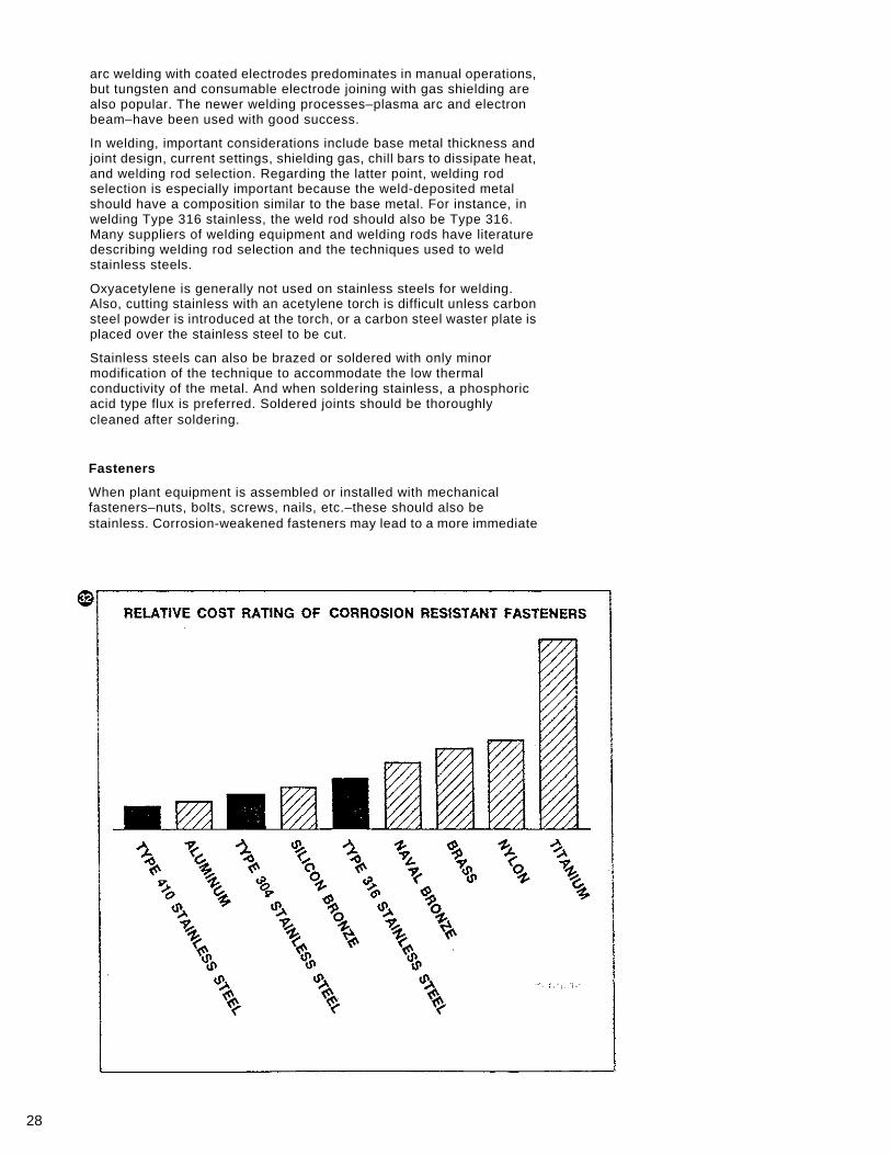
When plant equipment is assembled or installed with mechanical fasteners–nuts, bolts, screws, nails, etc.–these should also be stainless. Corrosion-weakened fasteners may lead to a more immediate
29
failure with more serious consequences than an equal amount of corrosive attack elsewhere in the plant. Stainless steel fasteners also prevent unsightly rust staining and they facilitate maintenance if a piece of equipment is removed from service.
Stainless steel fasteners of all sizes and descriptions are readily available from steel service centers, industrial supply houses, distributors, and manufacturers. And, as the chart in Figure 32 shows, they are no more expensive than other corrosion resistant fasteners. The chart compares the cost of a ¼"-20 by ¾" hexhead machine bolt made of nine different materials.
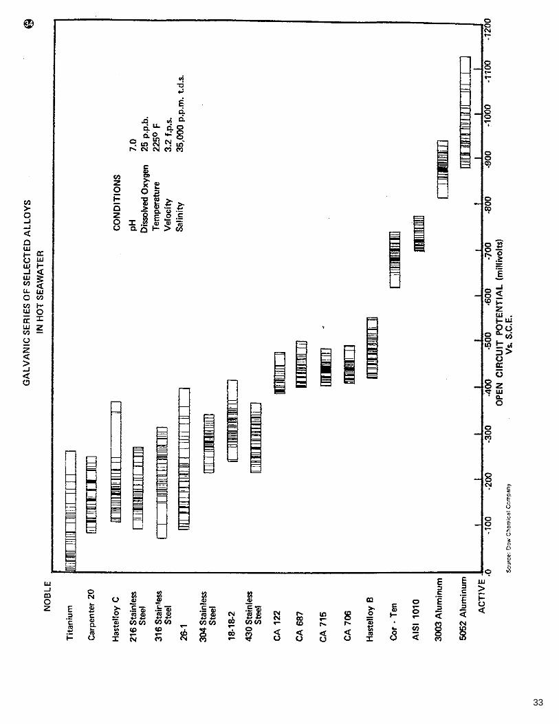
In fastening various components, consideration should be given to galvanic corrosion that can be caused by joining dissimilar metals. Figure 34, a chart showing the galvanic series of selected alloys in hot seawater, can provide some guidance in this direction.
TIPS ON DESIGNING WITH STAINLESS STEELS
In designing stainless steel equipment for desalting service, it is desirable to adhere to certain basic concepts from the standpoints of both corrosion resistance and mechanical behavior. Of course, such perfection is not always obtainable and equipment with less than ideal design may serve satisfactorily, but at least the designer and user should be aware of the goals to have in mind for optimum performance.
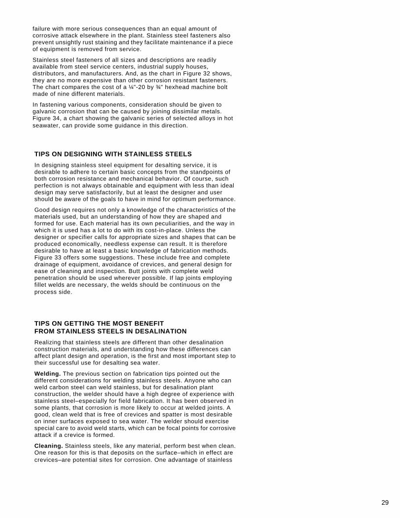
Good design requires not only a knowledge of the characteristics of the materials used, but an understanding of how they are shaped and formed for use. Each material has its own peculiarities, and the way in which it is used has a lot to do with its cost-in-place. Unless the designer or specifier calls for appropriate sizes and shapes that can be produced economically, needless expense can result. It is therefore desirable to have at least a basic knowledge of fabrication methods. Figure 33 offers some suggestions. These include free and complete drainage of equipment, avoidance of crevices, and general design for ease of cleaning and inspection. Butt joints with complete weld penetration should be used wherever possible. If lap joints employing fillet welds are necessary, the welds should be continuous on the process side.
TIPS ON GETTING THE MOST BENEFIT FROM STAINLESS STEELS IN DESALINATION
Realizing that stainless steels are different than other desalination construction materials, and understanding how these differences can affect plant design and operation, is the first and most important step to their successful use for desalting sea water.
Welding. The previous section on fabrication tips pointed out the different considerations for welding stainless steels. Anyone who can weld carbon steel can weld stainless, but for desalination plant construction, the welder should have a high degree of experience with stainless steel–especially for field fabrication. It has been observed in some plants, that corrosion is more likely to occur at welded joints. A good, clean weld that is free of crevices and spatter is most desirable on inner surfaces exposed to sea water. The welder should exercise special care to avoid weld starts, which can be focal points for corrosive attack if a crevice is formed.
Cleaning. Stainless steels, like any material, perform best when clean. One reason for this is that deposits on the surface–which in effect are crevices–are potential sites for corrosion. One advantage of stainless
30
steels relative to cleanliness is that they generally remain clean longer than other materials in identical service; and since stainless steels are not subject to general corrosion or roughening of the surface, they are easier to clean when cleaning does become necessary.
It is reported that many plants use hydrochloric acid for cleaning. The use of this acid is strongly discouraged in plants constructed with stainless steels. A substitute that is preferred for stainless is sulfamic (or even formic) acid. Any cleaning acid, of course, should be used under the supervision of a qualified metallurgist or corrosion engineer.
Also, when a plant is shut down for any length of time, it should be thoroughly flushed with fresh water and then drained to eliminate stagnant water. Good drainage is a result of good design, as pointed out in previous sections of this booklet.
Operation. Desalination plants will get the best performance from stainless steels, and other construction materials for that matter, when operating conditions remain within design parameters, especially in terms of deaeration, pH control, and velocity. A recent paper by Manning and Carleton (23) describes some of the effects of upset conditions on corrosion rates.
31
Relative to dissolved oxygen, it was found to be one of the most detrimental water chemistry variables affecting corrosion. The elimination or reduction of dissolved oxygen to the low range of 5 to 20 ppb by good deaeration in pretreatment and the prevention of subsequent air inleakage in the vacuum portions of the plant is essential if there is to be acceptable control of corrosion. Since many plants operate at reduced pressures, the probability of air inleakage is enhanced. The results can be intolerable corrosion rates for most construction materials, and high oxygen levels in a hot brine environment can lead to stress-corrosion cracking of Type 316 stainless steel.
The lowering of pH to control calcium carbonate scale on heat exchange surfaces is a common practice, but one that can lead to high corrosion rates on Admiralty brass and mild steel. Good pH control is desirable.
Maintaining water velocities through the plant at design levels is also important because it helps to prevent fouling. Stainless steels generally can tolerate velocities higher than those used with other materials. Conversely, low velocity, as observed in the 3000-GPD stainless steel test plant, seems to have little deleterious effect on stainless steel surfaces.
CONCLUSION
More in-service experience with stainless steel in full-size plants is clearly desirable, because data so far indicate that stainless steels can be used effectively to control corrosion in hot, deaerated brine environments. As confidence continues to increase, as evidenced by the growing use of stainless steels for repair or replacement of corroded components, more in-service experience will become available.
32
REFERENCES
(1) V. B. Chernozubov, et. al. "Corrosion Resistance of Materials in Sea Water," paper presented at First international Symposium of Water Desalination, October 1965, Washington, D.C.
(2) F. P. Zaotrovsky, et. al. "Distillation Desalination Plant in the City at Shevchenko. Layout, Equipment, and Operating Experience," DESALINATION 1, (1966), pp 165-177.
(3) R. T. Jones, "Application of Steels for Desalination Plants," METALS ENGINEERING 7, No. 3 (August 1967), pp 37-48.
(4) E. H. Phelps, R. T. Jones, and H. P. Leckie, "Application of Stainless Steels in Desalination Equipment." Presented at a symposium on materials for desalination plant equipment, annual meeting of the Electrochemical Society, October 10, 1968, Montreal.
(5) P. F. George and J. R. Newton, "Evaluation of Stainless Steel in the 1-MGD Test Bed Plant in Freeport, Texas," private communication to AISI, November 1971.
(6) J. R. Newton, et. al. "Final Probolog Testing of the Original 12-Effect, 1-MGD Test Bed Plant in Freeport, Texas," report to OSW, October 1970.
(7) C. F. Schrieber and H. A. Diehl, "Evaluation of Selected Tubes from the Dismantled OSW 1-MGD Test Bed Plant in Freeport, Texas," report to OSW, January 1971.
(8) Anon, "Pitting Evaluation of Type 316 Stainless Steel Tubes from the VTE Eighth Effect of 1-MGD Test Bed Plant After About Four Years of Operation," private communication from C. F. Schrieber to AISI, March 1974.
(9) E. H. Newton and J. D. Birkett, "Survey of Materials Behavior in Multistage Flash Distillation Plants," A. D. Little Company, Contract 14-01-0001-956, August 1968.
(10) E- H. Newton, J. D. Birkett and J. M. Ketteringham, "Survey of Materials Behavior in Large Desalting Plants Around the World," A. D. Little Company, Contract 14-30-2721, March 1972.
(11) "Evaluating Material Performance in 3000-GPD Stainless Steel Desalination Test Plant ... 36 Months' Operation," report prepared by the Desalination Subcommittee, Committee of Stainless Steel Producers, American Iron and Steel Institute, April 1973.
(12) J. C. Coakley, Jr., "Four Years Experience with Stainless Steel Condenser Tubing," Proceedings of the American Power Conference, Vol. 21, pp. 729-737, 1959.
(13) R. V. Hall, "Factors in Over-all Heat Transfer of Condenser Tubes," Proceedings, 18th Annual Water Conference, Engineer's Society of Western sylvania, pp. 92-95.
(14) C. F. Schrieber in private communication to AISI, March 1974. (15) J. A. Potter, Jr. "Solving Heat Transfer Problems Graphically," CHEMICAL
AND METALLURGICAL ENGINEERING, Vol. 32, pp. 690-691. (16) E. R. Long, "Experiences With the Use of Stainless Steel Condenser
Tubes at the Rivesville Station," 20th Annual Water Conference, Engineer's Society of Western Pennsylvania, October 26, 1959.
(17) E. R. Long, "Stainless Steel Ups Condenser Tube Life 300%," ELECTRIC LIGHT AND POWER, January 15, 1964, pp. 54.
(18) R. H. Pell, "Performance of Stainless Condsenser Tubes," ASME Paper NY No. 60-WA-217.
(19) D. W. Hoskinson and C. K. Kuester, "Operating Experiences With Stainless Steel Condenser Tubes in Central Stations," ASME Paper No. 64-WA/CT-1.
(20) R. A. McAllister, D. H. Eastman, N.A. Dougharty, and M. Hollier, "A Study of Scaling and Corrosion in Condenser Tubes Exposed to River Water," CORROSION, Vol. 17, No. 12, pp. 579t-588t.
(21) C. F. Schrieber, T. D. Boyce, and B. D. Oakes, "Behavior of Metals in Desalting Environments–Sixth Progress Report," NACE Paper No. 139, March 1974.
(22) M. M. Stille, "Tampa Electric Goes Stainless," POWER ENGINEERING, May 1971, pp. 44-45.
(23) J. A. Manning and S. V. Carleton, "A Study of Corrosion Rates in an Operating Desalting, Plant," NACE Paper No. 140, March 1974.
(24) E. L. Lustenader and F. W. Staub, "Development Contribution to Compact Condenser Design," The International Nickel Company Power Conference, May 1964 (Unpublished).
(25) R. V. Jelinek, "Design Factors in Corrosion Control," CHEMICAL ENGINEERING 65 (1958) No. 23, pp. 151-154.
(26) J. A. Collins, "Effects of Design, Fabrication, and Installation on the Performance of Stainless Steel Equipment," CORROSION 11 (1955), pp. 11-18.
33


![Martensitic Stainless Steels - IJSER · PDF fileMartensitic Stainless Steels ... tempering temperature range for martensitic stainless steels is normally from 480. 0. C. [9] With in](https://img.dokumen.tips/doc/110x75/5a7685847f8b9aea3e8d537d/martensitic-stainless-steels-ijser-a-martensitic-stainless-steels-tempering.jpg)


![Stainless Steels[1]](https://img.dokumen.tips/doc/110x75/577cda5d1a28ab9e78a57bc0/stainless-steels1.jpg)