Embed Size (px)
Citation preview

OverviewThis paper relates two heat sinks, a medical suction device, a household oven, and an industrial control valve as examples that illustrate how SolidWorks® Flow Simulation can help design engineers create the best possible product designs when dealing with heat transfer and fluid flow problems. SolidWorks Flow Simulation is an intelligent, easy-to-use computational fluid dynamics (CFD) program that will facilitate the work of design engineers who use SolidWorks 3D CAD software for design creation.
THE ROLE OF CFD IN REAL LIFE DESIGNS
W H I T E P A P E R

The SolidWorks Flow Simulation approach
Heat transfer problems always crop up when design engineers work on electronic products that can be damaged easily by overheating. Heat sinks solve the overheating problem—but what’s the best heat sink design and placement for a given electronic device? And how can a design engineer choose the best, most cost-effective heat sink for his purpose without building and breaking many costly prototypes?
Completely different kinds of problems occur when designing a medical suction device for an application that needs the highest possible flow rate for a given pressure drop (suction), with limited recirculation within the device, and the most uniform velocity profile possible at the suction head. Again, the question arises of how to choose the best design in the most cost- and time-effective way.
And the same principles hold true for consumer products, such as baking ovens, and for industrial equipment that includes control valves.
The examples mentioned above are problems that design engineers may face in their day-to-day work, and are also highly representative of the everyday problems encountered by designers of many different products.
Computational fluid dynamics (CFD) is a simulation tool that can be of great assistance in solving such problems. Very often, however, CFD programs are very complex and difficult to use, especially by design engineers who have not had a great deal of advanced education in the physics of fluid flows. SolidWorks Flow Simulation offers intelligent, easy-to-use CFD to design engineers who use SolidWorks 3D CAD software for design creation.
Design 1: Heat sink for external electronic device The first heat sink is meant for a piece of electronic equipment—say a surveillance camera—that will be used on the exterior of buildings. To protect it from the elements, the device has to be well sealed—but with no venting, most of the heat transfer will take place through one side of the enclosure only. The heat sink in this case has to aid in removing the heat. The manufacturer of the device has decided on an off-the-shelf heat sink, and its design can’t be changed.
How can the design engineer find cost-effective ways to increase the cooling within such circumscribed parameters?
Starting with a SolidWorks software model of the commercial heat sink (Figure 1), the designer can see that, as the force of gravity acts downwards, the heat from the enclosure will be conducted to the heat sink’s fins, and removed by lighter air rising—that is, natural convection. To test a “shield” design, the designer places a cover over the heat sink and then needs to determine whether that will generate a chimney effect—creating more air flow, and thus cooling the electronic product more effectively.
The Role of CFD in Real Life Designs 2
Very often, CFD programs are very complex and difficult to use, especially by design engineers who have not had a great deal of advanced education in the physics of fluid flows. SolidWorks Flow Simulation offers intelligent, easy-to-use CFD to design engineers who use SolidWorks 3D CAD software for design creation.

With SolidWorks Flow Simulation, the design engineer uses the program’s Project Wizard to set up the flow analysis.
The Role of CFD in Real Life Designs 3
Figure 1: Mandated Heat Sink
With SolidWorks Flow Simulation, the design engineer uses the program’s Project Wizard to set up the flow analysis. The Project Wizard lets the designer define the unit system to be used, the fluid as air, and the type of analysis as an external conjugate heat transfer problem; apply gravity to drive the flow for the free convection; input the ambient temperature and pressure conditions; and select the desired result resolution automatic meshing level—all within a single, easy-to-use interface.
The next step takes the engineer to the SolidWorks Flow Simulation analysis tree, where he can apply the heat power load on the heat sink with a simple right-click menu option that also walks him through setting the location for the load and power input.
Finally, the design engineer defines the overall design objectives of the analysis, maximum heat sink temperature, and maximum air velocity as goals, making it possible for him to monitor those values during the calculation and create a table of the computed values when the analysis has been completed.
Figure 2: Heat sink without shield Heat sink with shield
To determine whether the heat sink will perform better with or without the shield, the design engineer runs a SolidWorks Flow Simulation CFD analysis.
Table 1: Computed average temperature for each version of the design
Parameter Without Shield With Shield
Temperature (ºC) 62.0 55.9

The Role of CFD in Real Life Designs 4
Figure 3: Analysis results, showing velocity cuts. Warmer colors indicate higher vertical velocity. The design with the shield has greater velocity around the heat sink fins.
Figure 4: Velocity cuts through a vertical section. Results show that the version with the shield demonstrates far greater velocity within the model.
Figure 5: Temperature cuts through a cross-section. This result proves that the model with the shield transfers more heat to the air.
Figure 6: Solid temperature cuts through a cross-section. These results show that the model with the shield is dramatically cooler, with temperatures in a range from 55 ºC to 57 ºC. The heat sink without the shield has temperatures entirely above the 55 ºC to 57 ºC range.
The SolidWorks Flow Simulation studies show that the addition of a shield to a vertically mounted heat sink produces a significant increase in cooling—with a 10.9 percent decrease in average temperature when the two designs are compared.

The Role of CFD in Real Life Designs 5
To define the fan in this forced flow analysis, the designer can choose the appropriate fan profile from a list available in the Engineering Database built into SolidWorks Flow Simulation.
Design 2: Heat sink for the main chip in an electronic enclosure
The second heat sink needs to protect the main chip, installed with other electronic components, in an electronic enclosure. In this case, the design engineer needs to identify and select the best heat sink shape for the purpose.
Figure 7: Electronic enclosure model
The design shown in Figure 7 is a SolidWorks software assembly model of the electronic enclosure, including the main heat sink. An installed fan blows air into the enclosure, through the heat sink, and out through the outlet slots to cool the heated electronic components by forced convection. Which of two differently shaped commercially available heat sinks results in the lowest main chip temperature?
The design engineer can determine this with SolidWorks Flow Simulation in a very straightforward way. As in the previous analysis, the design engineer uses the Project Wizard to set up the internal conjugate heat transfer problem. To define the fan in this forced flow analysis, the designer can choose the appropriate fan profile from a list available in the Engineering Database built into SolidWorks Flow Simulation.
Next, the designer uses volumetric heat sources to represent the components heated during use software and sets goals of maximum and average temperatures of both the main chip and heat sink. When the analysis has been completed, he can view the resulting temperatures both as surface plots on the electrical components, and as cut plots through the fluid and solids. The design engineer can also create velocity vectors that make it easier to visualize flow patterns through which the fan blows air over the heat sink and around the entire enclosure.
Figure 8: Competing shapes of the heat sink SolidWorks Flow Simulation helps engineers compute the temperature of the electronic enclosure.
Table 2: Computed maximum and average temperatures of the main chip with each of the two heat sinks
The Role of CFD in Real Life Designs 6
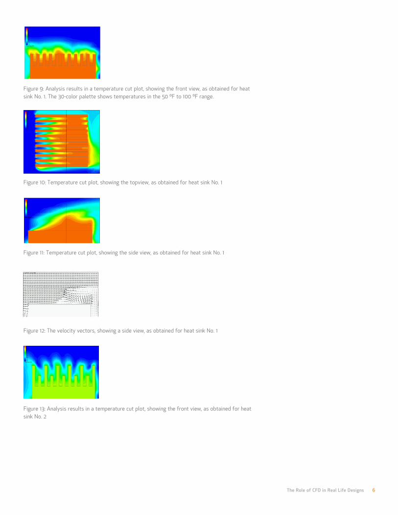
Figure 9: Analysis results in a temperature cut plot, showing the front view, as obtained for heat sink No. 1. The 30-color palette shows temperatures in the 50 ºF to 100 ºF range.
Figure 10: Temperature cut plot, showing the topview, as obtained for heat sink No. 1
Figure 11: Temperature cut plot, showing the side view, as obtained for heat sink No. 1
Figure 12: The velocity vectors, showing a side view, as obtained for heat sink No. 1
Figure 13: Analysis results in a temperature cut plot, showing the front view, as obtained for heat sink No. 2

The Role of CFD in Real Life Designs 7
The goal of the SolidWorks Flow Simulation analysis is to determine the flow rate at a given pressure drop for each of two screen designs.
Figure 14: Temperature cut plot, showing the top view, as obtained for heat sink No. 2
Figure 15: Temperature cut plot, showing the side view, as obtained for heat sink No. 2.
As the purpose of the SolidWorks Flow Simulation analysis was to enable the choice of the better heat sink shape for a main chip installed with other electronic components in an electronic enclosure, and the results show 17.5 percent reduction in solid temperatures in heat sink No. 2, that shape proved to be better.
Design 3: Medical suction device screen
In this design, the design engineer needs to identify the best screen shape for a medical suction device, to allow the highest flow rate for a given suction, limit recirculation within the device, and also create the most uniform velocity profile at the suction head.
Figure 16 shows the SolidWorks software assembly model of the device, including a screen with triangular cuts. Flow enters the device through a conical head, flows through the screen, and down the tube. The designer sets up the internal flow in the Project Wizard, and defines the inlet and outlet pressure conditions. The goal of the SolidWorks Flow Simulation analysis is to determine the flow rate at a given pressure drop for each of two screen designs—one with triangular cuts as shown in the model, and one with circular cuts—when installed in the suction device. Here, in addition to the computed volume flow rate, the engineer uses flow trajectories to show the paths taken by representative air molecules through the device. He can also create an animation of the flow trajectories to produce a better visualization of flow patterns and areas of recirculation.
Figure 16

The Role of CFD in Real Life Designs 8
Figure17:: The two screen shapes under study
Table 3: Computed volumetric flow rates of each screen shape
Figure 18: Pressure cut plots for each design. Both designs have similar pressure profiles.
Figure 19: Velocity cut plots with velocity vectors for each design. Both designs have similar velocity profiles at the suction head.
Figure 20: Trajectory plots showing recirculation zone
Figure 21: Trajectory plots in a recirculation zone for each design. While both designs have some recirculation, the zone for the triangular design is larger.

The Role of CFD in Real Life Designs 9
The objective of the SolidWorks Flow Simulation analysis is to learn which tray design will provide the optimal flow of heated air by studying the natural convection within the oven.
As stated above, the purpose of this analysis was to select the best performing screen head for the medical suction device. The results show a 7.8 percent higher flow rate when using the screen with circular cuts, and both designs have reasonably equal velocity profiles at the suction head. The circular cut design, however, has a smaller recirculation zone—making it clear that the circular cut design will provide superior performance, based upon the original design criteria.
Design 4: Household Oven
In this design of a household baking oven, the design engineer can use SolidWorks Flow Simulation to study the air flow pattern and temperature distribution, and optimize the design to achieve the uniform hot air circulation required for uniform baking. The CFD program enables study of heat transfer by conduction, convection, and radiation within the oven.
Figure 22 shows the SolidWorks software model of the oven, with three baking trays and cakes on each. The objective of the SolidWorks Flow Simulation analysis is to optimize the flow of heated air, by studying the natural convection within the oven and checking the final surface temperature of the object being baked. To do this, the designer introduces hot air at 120 ºC into the oven chamber, raising the heat from an initial temperature of 20 ºC.
Figure 22: SolidWorks software model of oven with three baking trays and cakes
Figure 23: Temperature at the surface of the cakes for Design 1

The Role of CFD in Real Life Designs 10
Because hot air is lighter than cooler air, the hot air rises to the top, and the temperature decreases at lower heights.
SolidWorks Flow Simulation can also determine whether the performance of the oven will be more efficient if the designer adds air flow deflectors.
Figure 21 shows the surface temperature results, with uneven heating of the object placed on the stack of trays. Because hot air is lighter than cooler air, the hot air rises to the top, and the temperature decreases at lower heights.
The design engineer uses the wizard to set up a simulation of internal flow by entering the initial oven temperature. He defines the velocity of the hot air along with its temperature at the six inlets, as well as the pressure condition at the outlet. To visualize the results, the engineer can plot the temperature distribution around the baking object, and for better visualization of air flow distribution, he can plot flow trajectories and velocity contour plots at multiple sections.
SolidWorks Flow Simulation can also determine whether the performance of the oven will be more efficient if the designer adds air flow deflectors. And to optimize the design, the engineer can study both the ideal location and number of inlets that introduce hot air into the oven.
Figure 24: Air velocity and distribution at the top tray around the cake with Design 2
Figure 25: Air velocity and distribution at the bottom tray around the cake with the second design
Figure 26: Flow trajectories in the oven for the five-cutout tray, with temperatures

The Role of CFD in Real Life Designs 11
SolidWorks Flow Simulation makes it easy to calculate the pressures at the openings and through the entire model—a level of comprehensive information that cannot easily be obtained through physical testing.
In addition to plots, SolidWorks Flow Simulation can also produce a table showing the flow values at any point, surface, or volume within the model.
Design 5: Control valve
In this design, the engineer needs to optimize the design of a control valve for minimum pressure loss, and also to predict possible cavitation problems. The engineer uses CFD to perform an internal air flow simulation through the valve. CFD results give the engineer a detailed understanding of the flow pattern in such a valve by means of analysis results showing flow velocity, pressure, and particle trajectories. SolidWorks Flow Simulation makes it easy to calculate the pressures at the openings and through the entire model—a level of comprehensive information that cannot easily be obtained through physical testing because of the difficulty in placing instrumentation to provide sufficient information about what’s happening inside the valve.
Figure 27 shows the 3D SolidWorks software model of the valve. The design engineer sets up the simulation with the help of the SolidWorks Flow Simulation Wizard. He defines the velocity at which air enters the valve at the inlet, and applies static pressure equivalent to the atmosphere at the outlet.
Figure 27: SolidWorks 3D valve model
Figure 28: Velocity distribution with gradient vectors shown throughout the model
Figure 29: Velocity trajectories help in the study of the flow pattern.

Figure 30: Pressure distribution plot with isobars shows the possibility of cavitation—which proves not to be a problem in the case of this control valve.
The pressure result plot shows minimum loss of pressure for this valve design. The pressure at the region where cavitation could occur became negative, indicating that the valve would not experience cavitation. In addition to plots, SolidWorks Flow Simulation can also produce a table showing the flow values at any point, surface, or volume within the model.
Conclusion
Whether designing heat sinks for electronic products, medical suction devices, consumer products, or industrial control valves, design engineers need to know which design is best, while avoiding the extra costs and time involved in building too many prototypes in order to achieve their goals. Computational fluid dynamics simulation tools can help meet this challenge. SolidWorks Flow Simulation is an intelligent, easy-to-use tool that allows you to test multiple designs and scenarios to study heat transfer and fluid flow problems so you can optimize your design without spending excess time and money in the process.
SolidWorks is a registered trademark of Dassault Systèmes SolidWorks Corp. All other company and product names are trademarks or registered trademarks of their respective owners. ©2010 Dassault Systèmes. All rights reserved. MKCFDWPENG1210
Dassault Systèmes SolidWorks Corp. 300 Baker Avenue Concord, MA 01742 USA Phone: 1 800 693 9000 Outside the US: +1 978 371 5011 Email: [email protected] www.solidworks.com