Embed Size (px)
Citation preview

The RISC-V Instruction Set ManualVolume II: Privileged ArchitecturePrivileged Architecture Version 1.9draft:
Document Version 1.9draft:Warning! This draft specification will change before being accepted as
standard, so implementations made to this draft specification will likely notconform to the future standard.
Andrew Waterman, Yunsup Lee, Rimas Avizienis, David Patterson, Krste AsanovicCS Division, EECS Department, University of California, Berkeley{waterman|yunsup|rimas|pattrsn|krste}@eecs.berkeley.edu
June 9, 2016
An earler version of this document is also available as Technical Report UCB/EECS-2015-49.

2

Contents
1 Introduction 1
1.1 RISC-V Hardware Platform Terminology . . . . . . . . . . . . . . . . . . . . . . . . 1
1.2 RISC-V Privileged Software Stack Terminology . . . . . . . . . . . . . . . . . . . . . 2
1.3 Privilege Levels . . . . . . . . . . . . . . . . . . . . . . . . . . . . . . . . . . . . . . . 4
2 Control and Status Registers (CSRs) 7
2.1 CSR Address Mapping Conventions . . . . . . . . . . . . . . . . . . . . . . . . . . . 7
2.2 CSR Listing . . . . . . . . . . . . . . . . . . . . . . . . . . . . . . . . . . . . . . . . . 9
2.3 CSR Field Specifications . . . . . . . . . . . . . . . . . . . . . . . . . . . . . . . . . . 14
3 Machine-Level ISA 17
3.1 Machine-Level CSRs . . . . . . . . . . . . . . . . . . . . . . . . . . . . . . . . . . . . 17
3.1.1 Machine-Mode ISA Register misa . . . . . . . . . . . . . . . . . . . . . . . . 17
3.1.2 Machine Vendor ID Register mvendorid . . . . . . . . . . . . . . . . . . . . . 20
3.1.3 Machine Architecture ID Register marchid . . . . . . . . . . . . . . . . . . . 20
3.1.4 Machine Implementation ID Register mimpid . . . . . . . . . . . . . . . . . . 20
3.1.5 Hart ID Register mhartid . . . . . . . . . . . . . . . . . . . . . . . . . . . . . 21
3.1.6 Machine Status Register (mstatus) . . . . . . . . . . . . . . . . . . . . . . . . 21
3.1.7 Privilege and Global Interrupt-Enable Stack in mstatus register . . . . . . . 21
3.1.8 Virtualization Management Field in mstatus Register . . . . . . . . . . . . . 22
3.1.9 Memory Privilege in mstatus Register . . . . . . . . . . . . . . . . . . . . . . 24
3.1.10 Extension Context Status in mstatus Register . . . . . . . . . . . . . . . . . 24
3

4
3.1.11 Machine Trap-Vector Base-Address Register (mtvec) . . . . . . . . . . . . . . 27
3.1.12 Machine Trap Delegation Registers (medeleg and mideleg) . . . . . . . . . . 28
3.1.13 Machine Interrupt Registers (mip and mie) . . . . . . . . . . . . . . . . . . . 29
3.1.14 Machine Timer Registers (mtime and mtimecmp) . . . . . . . . . . . . . . . . 31
3.1.15 Machine Performance Counters (mcycle, minstret) . . . . . . . . . . . . . . 32
3.1.16 Machine Counter-Enable Registers (m[h|s|u]counteren) . . . . . . . . . . . 33
3.1.17 Machine Counter-Delta Registers . . . . . . . . . . . . . . . . . . . . . . . . . 33
3.1.18 Machine Scratch Register (mscratch) . . . . . . . . . . . . . . . . . . . . . . 34
3.1.19 Machine Exception Program Counter (mepc) . . . . . . . . . . . . . . . . . . 35
3.1.20 Machine Cause Register (mcause) . . . . . . . . . . . . . . . . . . . . . . . . 35
3.1.21 Machine Bad Address (mbadaddr) Register . . . . . . . . . . . . . . . . . . . 36
3.2 Machine-Mode Privileged Instructions . . . . . . . . . . . . . . . . . . . . . . . . . . 37
3.2.1 Instructions to Change Privilege Level . . . . . . . . . . . . . . . . . . . . . . 37
3.2.2 Wait for Interrupt . . . . . . . . . . . . . . . . . . . . . . . . . . . . . . . . . 37
3.3 Reset . . . . . . . . . . . . . . . . . . . . . . . . . . . . . . . . . . . . . . . . . . . . . 38
3.4 Non-Maskable Interrupts . . . . . . . . . . . . . . . . . . . . . . . . . . . . . . . . . . 39
3.5 Physical Memory Attributes . . . . . . . . . . . . . . . . . . . . . . . . . . . . . . . . 39
3.5.1 Main Memory versus I/O versus Empty Regions . . . . . . . . . . . . . . . . 40
3.5.2 Supported Access Type PMAs . . . . . . . . . . . . . . . . . . . . . . . . . . 41
3.5.3 Atomicity PMAs . . . . . . . . . . . . . . . . . . . . . . . . . . . . . . . . . . 41
3.5.4 Memory-Ordering PMAs . . . . . . . . . . . . . . . . . . . . . . . . . . . . . 42
3.5.5 Coherence and Cacheability PMAs . . . . . . . . . . . . . . . . . . . . . . . . 42
3.5.6 Idempotency PMAs . . . . . . . . . . . . . . . . . . . . . . . . . . . . . . . . 43
3.6 Physical Memory Protection . . . . . . . . . . . . . . . . . . . . . . . . . . . . . . . . 44
3.7 Mbare addressing environment . . . . . . . . . . . . . . . . . . . . . . . . . . . . . . 44
3.8 Base-and-Bound environments . . . . . . . . . . . . . . . . . . . . . . . . . . . . . . 44
3.8.1 Mbb: Single Base-and-Bound registers (mbase, mbound) . . . . . . . . . . . . 45
3.8.2 Mbbid: Separate Instruction and Data Base-and-Bound registers . . . . . . . 45

5
4 Supervisor-Level ISA 47
4.1 Supervisor CSRs . . . . . . . . . . . . . . . . . . . . . . . . . . . . . . . . . . . . . . 47
4.1.1 Supervisor Status Register (sstatus) . . . . . . . . . . . . . . . . . . . . . . 48
4.1.2 Memory Privilege in sstatus Register . . . . . . . . . . . . . . . . . . . . . . 48
4.1.3 Supervisor Trap Vector Base Address Register (stvec) . . . . . . . . . . . . . 49
4.1.4 Supervisor Interrupt Registers (sip and sie) . . . . . . . . . . . . . . . . . . 49
4.1.5 Supervisor Time Register (stime) . . . . . . . . . . . . . . . . . . . . . . . . 50
4.1.6 Supervisor Performance Counters (scycle, sinstret) . . . . . . . . . . . . . 50
4.1.7 Supervisor Scratch Register (sscratch) . . . . . . . . . . . . . . . . . . . . . 51
4.1.8 Supervisor Exception Program Counter (sepc) . . . . . . . . . . . . . . . . . 51
4.1.9 Supervisor Cause Register (scause) . . . . . . . . . . . . . . . . . . . . . . . 52
4.1.10 Supervisor Bad Address (sbadaddr) Register . . . . . . . . . . . . . . . . . . 52
4.1.11 Supervisor Page-Table Base Register (sptbr) . . . . . . . . . . . . . . . . . . 53
4.1.12 Supervisor Address Space ID Register (sasid) . . . . . . . . . . . . . . . . . 53
4.2 Supervisor Instructions . . . . . . . . . . . . . . . . . . . . . . . . . . . . . . . . . . . 54
4.2.1 Supervisor Memory-Management Fence Instruction . . . . . . . . . . . . . . . 54
4.3 Supervisor Operation in Mbare Environment . . . . . . . . . . . . . . . . . . . . . . 55
4.4 Supervisor Operation in Base and Bounds Environments . . . . . . . . . . . . . . . . 55
4.5 Sv32: Page-Based 32-bit Virtual-Memory Systems . . . . . . . . . . . . . . . . . . . 55
4.5.1 Addressing and Memory Protection . . . . . . . . . . . . . . . . . . . . . . . 55
4.5.2 Virtual Address Translation Process . . . . . . . . . . . . . . . . . . . . . . . 57
4.6 Sv39: Page-Based 39-bit Virtual-Memory System . . . . . . . . . . . . . . . . . . . . 58
4.6.1 Addressing and Memory Protection . . . . . . . . . . . . . . . . . . . . . . . 58
4.7 Sv48: Page-Based 48-bit Virtual-Memory System . . . . . . . . . . . . . . . . . . . . 59
4.7.1 Addressing and Memory Protection . . . . . . . . . . . . . . . . . . . . . . . 59
5 Hypervisor-Level ISA 61
6 Platform-Level Interrupt Controller (PLIC) 63

6
6.1 PLIC Overview . . . . . . . . . . . . . . . . . . . . . . . . . . . . . . . . . . . . . . . 63
6.2 Interrupt Sources . . . . . . . . . . . . . . . . . . . . . . . . . . . . . . . . . . . . . . 63
6.2.1 Local Interrupt Sources . . . . . . . . . . . . . . . . . . . . . . . . . . . . . . 64
6.2.2 Global Interrupt Sources . . . . . . . . . . . . . . . . . . . . . . . . . . . . . . 65
6.3 Interrupt Targets and Hart Contexts . . . . . . . . . . . . . . . . . . . . . . . . . . . 65
6.4 Interrupt Gateways . . . . . . . . . . . . . . . . . . . . . . . . . . . . . . . . . . . . . 65
6.5 Interrupt Identifiers (IDs) . . . . . . . . . . . . . . . . . . . . . . . . . . . . . . . . . 66
6.6 Interrupt Priorities . . . . . . . . . . . . . . . . . . . . . . . . . . . . . . . . . . . . . 66
6.7 Interrupt Enables . . . . . . . . . . . . . . . . . . . . . . . . . . . . . . . . . . . . . . 67
6.8 Interrupt Priority Thresholds . . . . . . . . . . . . . . . . . . . . . . . . . . . . . . . 67
6.9 Interrupt Notifications . . . . . . . . . . . . . . . . . . . . . . . . . . . . . . . . . . . 68
6.10 Interrupt Claims . . . . . . . . . . . . . . . . . . . . . . . . . . . . . . . . . . . . . . 68
6.11 Interrupt Completion . . . . . . . . . . . . . . . . . . . . . . . . . . . . . . . . . . . . 69
6.12 Interrupt Flow . . . . . . . . . . . . . . . . . . . . . . . . . . . . . . . . . . . . . . . 69
6.13 PLIC Core Specification . . . . . . . . . . . . . . . . . . . . . . . . . . . . . . . . . . 70
6.14 Controlling Access to the PLIC . . . . . . . . . . . . . . . . . . . . . . . . . . . . . . 70
7 RISC-V Privileged Instruction Set Listings 71
8 Machine Configuration Strings 73
9 History 75
9.1 Funding . . . . . . . . . . . . . . . . . . . . . . . . . . . . . . . . . . . . . . . . . . . 75

Chapter 1
Introduction
This is a draft of the privileged architecture description document for RISC-V. This version doesnot match our existing implementations. Feedback welcome. Changes will occur before the finalrelease.
This document describes the RISC-V privileged architecture, which covers all aspects of RISC-Vsystems beyond the user-level ISA, including privileged instructions as well as additional function-ality required for running operating systems and attaching external devices.
Commentary on our design decisions is formatted as in this paragraph, and can be skipped if thereader is only interested in the specification itself.
We briefly note that the entire privileged-level design described in this document could be replacedwith an entirely different privileged-level design without changing the user-level ISA, and pos-sibly without even changing the ABI. In particular, this privileged specification was designed torun existing popular operating systems, and so embodies the conventional level-based protectionmodel. Alternate privileged specifications could embody other more flexible protection domainmodels.
1.1 RISC-V Hardware Platform Terminology
A RISC-V hardware platform can contain one or more RISC-V-compatible processing cores to-gether with other non-RISC-V-compatible cores, fixed-function accelerators, various physical mem-ory structures, I/O devices, and an interconnect structure to allow the components to communicate.
A component is termed a core if it contains an independent instruction fetch unit. A RISC-V-compatible core might support multiple RISC-V-compatible hardware threads, or harts, throughmultithreading.
A RISC-V core might have additional specialized instruction set extensions or an added coprocessor.We use the term coprocessor to refer to a unit that is attached to a RISC-V core and is mostlysequenced by a RISC-V instruction stream, but which contains additional architectural state andinstruction set extensions, and possibly some limited autonomy relative to the primary RISC-Vinstruction stream.
1

2 1.9draft: Volume II: RISC-V Privileged Architectures
We use the term accelerator to refer to either a non-programmable fixed-function unit or a core thatcan operate autonomously but is specialized for certain tasks. In RISC-V systems, we expect manyprogrammable accelerators will be RISC-V-based cores with specialized instruction set extensionsand/or customized coprocessors. An important class of RISC-V accelerators are I/O accelerators,which offload I/O processing tasks from the main application cores.
The system-level organization of a RISC-V hardware platform can range from a single-core micro-controller to a many-thousand-node cluster of shared-memory manycore server nodes. Even smallsystems-on-a-chip might be structured as a hierarchy of multicomputers and/or multiprocessors tomodularize development effort or to provide secure isolation between subsystems.
This document focuses on the privileged architecture visible to each hart (hardware thread) runningwithin a uniprocessor or a shared-memory multiprocessor.
1.2 RISC-V Privileged Software Stack Terminology
This section describes the terminology we use to describe components of the wide range of possibleprivileged software stacks for RISC-V.
Figure 1.1 shows some of the possible software stacks that can be supported by the RISC-V archi-tecture. The left-hand side shows a simple system that supports only a single application runningon an application execution environment (AEE). The application is coded to run with a particularapplication binary interface (ABI). The ABI includes the supported user-level ISA plus a set ofABI calls to interact with the AEE. The ABI hides details of the AEE from the application to al-low greater flexibility in implementing the AEE. The same ABI could be implemented natively onmultiple different host OSs, or could be supported by a user-mode emulation environment runningon a machine with a different native ISA.
ApplicationABIAEE
ApplicationABI
OSSBISEE
ApplicationABI
SBIHypervisor
ApplicationABI
OS
ApplicationABI
ApplicationABI
OS
ApplicationABI
SBI
HBIHEE
Figure 1.1: Different implementation stacks supporting various forms of privileged execution.
Our graphical convention represents abstract interfaces using black boxes with white text, toseparate them from concrete instances of components implementing the interfaces.
The middle configuration shows a conventional operating system (OS) that can support multipro-grammed execution of multiple applications. Each application communicates over an ABI withthe OS, which provides the AEE. Just as applications interface with an AEE via an ABI, RISC-Voperating systems interface with a supervisor execution environment (SEE) via a supervisor binaryinterface (SBI). An SBI comprises the user-level and supervisor-level ISA together with a set of

Copyright (c) 2010–2016, The Regents of the University of California. All rights reserved. 3
SBI function calls. Using a single SBI across all SEE implementations allows a single OS binaryimage to run on any SEE. The SEE can be a simple boot loader and BIOS-style IO system in alow-end hardware platform, or a hypervisor-provided virtual machine in a high-end server, or athin translation layer over a host operating system in an architecture simulation environment.
Most supervisor-level ISA definitions do not separate the SBI from the execution environmentand/or the hardware platform, complicating virtualization and bring-up of new hardware plat-forms.
The rightmost configuration shows a virtual machine monitor configuration where multiple multi-programmed OSs are supported by a single hypervisor. Each OS communicates via an SBI withthe hypervisor, which provides the SEE. The hypervisor communicates with the hypervisor execu-tion environment (HEE) using a hypervisor binary interface (HBI), to isolate the hypervisor fromdetails of the hardware platform.
The various ABI, SBI, and HBIs are still a work-in-progress, but we anticipate the SBI and HBIto support devices via virtualized device interfaces similar to virtio [3], and to support devicediscovery. In this manner, only one set of device drivers need be written that can support anyOS or hypervisor, and which can also be shared with the boot environment.
Hardware implementations of the RISC-V ISA will generally require additional features beyond theprivileged ISA to support the various execution environments (AEE, SEE, or HEE). We separatethe features required in a hardware platform from the execution environments using a hardwareabstraction layer (HAL), as shown in Figure 1.2. Note that a HAL is not necessarily presentin a RISC-V software stack, as an execution environment might be provided purely via softwareemulation or might have been written directly to a given hardware platform without abstraction.
Later chapters provide details of proposed standard designs for RISC-V hardware platforms.
ApplicationABIAEEHAL
Hardware
ApplicationABI
OSSBISEE
ApplicationABI
HALHardware
SBIHypervisor
ApplicationABI
OS
ApplicationABI
ApplicationABI
OS
ApplicationABI
SBI
HBIHEE
HardwareHAL
Figure 1.2: Hardware abstraction layers (HALs) abstract underlying hardware platforms from theexecution environments.

4 1.9draft: Volume II: RISC-V Privileged Architectures
1.3 Privilege Levels
At any time, a RISC-V hardware thread (hart) is running at some privilege level encoded as a modein one or more CSRs (control and status registers). Four RISC-V privilege levels are currentlydefined as shown in Table 1.1.
Level Encoding Name Abbreviation
0 00 User/Application U1 01 Supervisor S2 10 Hypervisor H3 11 Machine M
Table 1.1: RISC-V privilege levels.
Privilege levels are used to provide protection between different components of the software stack,and attempts to perform operations not permitted by the current privilege mode will cause anexception to be raised. These exceptions will normally cause traps into an underlying executionenvironment or the HAL.
The machine level has the highest privileges and is the only mandatory privilege level for a RISC-Vhardware platform. Code run in machine-mode (M-mode) is inherently trusted, as it has low-levelaccess to the machine implementation. M-mode is used to manage secure execution environmentson RISC-V. User-mode (U-mode) and supervisor-mode (S-mode) are intended for conventionalapplication and operating system usage respectively, while hypervisor-mode (H-mode) is intendedto support virtual machine monitors.
Each privilege level has a core set of privileged ISA extensions with optional extensions and variants.For example, machine-mode supports several optional standard variants for address translation andmemory protection.
Although none are currently defined, future hypervisor-level ISA extensions will be added toimprove virtualization performance. One common feature to support hypervisors is to providea second level of translation and protection, from supervisor physical addresses to hypervisorphysical addresses.
Implementations might provide anywhere from 1 to 4 privilege modes trading off reduced isolationfor lower implementation cost, as shown in Table 1.2.
In the description, we try to separate the privilege level for which code is written, from theprivilege mode in which it runs, although the two are often tied. For example, a supervisor-level operating system can run in supervisor-mode on a system with three privilege modes, butcan also run in user-mode under a classic virtual machine monitor on systems with two ormore privilege modes. In both cases, the same supervisor-level operating system binary code canbe used, coded to a supervisor-level SBI and hence expecting to be able to use supervisor-levelprivileged instructions and CSRs. When running a guest OS in user mode, all supervisor-levelactions will be trapped and emulated by the SEE running in the higher-privilege level.
All hardware implementations must provide M-mode, as this is the only mode that has unfetteredaccess to the whole machine. The simplest RISC-V implementations may provide only M-mode,

Copyright (c) 2010–2016, The Regents of the University of California. All rights reserved. 5
Number of levels Supported Modes
1 M2 M, U3 M, S, U4 M, H, S, U
Table 1.2: Supported combinations of privilege modes.
though this will provide no protection against incorrect or malicious application code. Many RISC-V implementations will also support at least user mode (U-mode) to protect the rest of the systemfrom application code. Supervisor mode (S-mode) can be added to provide isolation between asupervisor-level operating system and the SEE and HAL code. The hypervisor mode (H-mode) isintended to provide isolation between a virtual machine monitor and a HEE and HAL running inmachine mode.
A hart normally runs application code in U-mode until some trap (e.g., a supervisor call or a timerinterrupt) forces a switch to a trap handler, which usually runs in a more privileged mode. The hartwill then execute the trap handler, which will eventually resume execution at or after the originaltrapped instruction in U-mode. Traps that increase privilege level are termed vertical traps, whiletraps that remain at the same privilege level are termed horizontal traps. The RISC-V privilegedarchitecture provides flexible routing of traps to different privilege layers.
Horizontal traps can be implemented as vertical traps that return control to a horizontal traphandler in the less-privileged mode.

6 1.9draft: Volume II: RISC-V Privileged Architectures

Chapter 2
Control and Status Registers (CSRs)
The SYSTEM major opcode is used to encode all privileged instructions in the RISC-V ISA. Thesecan be divided into two main classes: those that atomically read-modify-write control and statusregisters (CSRs), and all other privileged instructions. In addition to the user-level state describedin Volume I of this manual, an implementation may contain additional CSRs, accessible by somesubset of the privilege levels using the CSR instructions described in the user-level manual. Inthis chapter, we map out the CSR address space. The following chapters describe the function ofeach of the CSRs according to privilege level, as well as the other privileged instructions whichare generally closely associated with a particular privilege level. Note that although CSRs andinstructions are associated with one privilege level, they are also accessible at all higher privilegelevels.
2.1 CSR Address Mapping Conventions
The standard RISC-V ISA sets aside a 12-bit encoding space (csr[11:0]) for up to 4,096 CSRs.By convention, the upper 4 bits of the CSR address (csr[11:8]) are used to encode the read andwrite accessibility of the CSRs according to privilege level as shown in Table 2.1. The top two bits(csr[11:10]) indicate whether the register is read/write (00, 01, or 10) or read-only (11). The nexttwo bits (csr[9:8]) encode the lowest privilege level that can access the CSR.
The CSR address convention uses the upper bits of the CSR address to encode default accessprivileges. This simplifies error checking in the hardware and provides a larger CSR space, butdoes constrain the mapping of CSRs into the address space.
Implementations might allow a more-privileged level to trap otherwise permitted CSR ac-cesses by a less-privileged level to allow these accesses to be intercepted. This change should betransparent to the less-privileged software.
Attempts to access a non-existent CSR raise an illegal instruction exception. Attempts to access aCSR without appropriate privilege level or to write a read-only register also raise illegal instructionexceptions. A read/write register might also contain some bits that are read-only, in which casewrites to the read-only bits are ignored.
7

8 1.9draft: Volume II: RISC-V Privileged Architectures
CSR Address Hex Use and Accessibility[11:10] [9:8] [7:6]
User CSRs
00 00 XX 0x000-0x0FF Standard read/write01 00 XX 0x400-0x4FF Standard read/write10 00 XX 0x800-0x8FF Non-standard read/write11 00 00-10 0xC00-0xCBF Standard read-only11 00 11 0xCC0-0xCFF Non-standard read-only
Supervisor CSRs
00 01 XX 0x100-0x1FF Standard read/write01 01 00-10 0x500-0x5BF Standard read/write01 01 11 0x5C0-0x5FF Non-standard read/write10 01 00-10 0x900-0x9BF Standard read/write shadows10 01 11 0x9C0-0x9FF Non-standard read/write shadows11 01 00-10 0xD00-0xDBF Standard read-only11 01 11 0xDC0-0xDFF Non-standard read-only
Hypervisor CSRs
00 10 XX 0x200-0x2FF Standard read/write01 10 00-10 0x600-0x6BF Standard read/write01 10 11 0x6C0-0x6FF Non-standard read/write10 10 00-10 0xA00-0xABF Standard read/write shadows10 10 11 0xAC0-0xAFF Non-standard read/write shadows11 10 00-10 0xE00-0xEBF Standard read-only11 10 11 0xEC0-0xEFF Non-standard read-only
Machine CSRs
00 11 XX 0x300-0x3FF Standard read/write01 11 00-10 0x700-0x79F Standard read/write01 11 10 0x7A0-0x7BF Standard read/write debug CSRs01 11 11 0x7C0-0x7FF Non-standard read/write10 11 00-10 0xB00-0xBBF Standard read/write shadows10 11 11 0xBC0-0xBFF Non-standard read/write shadows11 11 00-10 0xF00-0xFAF Standard read-only11 11 11 0xFC0-0xFFF Non-standard read-only
Table 2.1: Allocation of RISC-V CSR address ranges.
Table 2.1 also indicates the convention to allocate CSR addresses between standard and non-standard uses. The CSR addresses reserved for non-standard uses will not be redefined by futurestandard extensions. The shadow addresses are reserved to provide a read-write address via whicha higher privilege level can modify a register that is read-only at a lower privilege level. Note thatif one privilege level has already allocated a read/write shadow address, then any higher privilegelevel can use the same CSR address for read/write access to the same register.
Effective virtualization requires that as many instructions run natively as possible inside a virtu-alized environment, while any privileged accesses trap to the virtual machine monitor [1]. CSRsthat are read-only at some lower privilege level are shadowed into separate CSR addresses if theyare made read-write at a higher privilege level. This avoids trapping permitted lower-privilege

Copyright (c) 2010–2016, The Regents of the University of California. All rights reserved. 9
accesses while still causing traps on illegal accesses.
Machine-mode standard read-only CSRs 0xFA0–0xFBF are reserved for use by the debug system.The prefered implementation is to raise illegal instruction exceptions on machine-mode access tothese registers, but implementations can allow read-only access to these registers.
2.2 CSR Listing
Tables 2.2–2.6 lists the CSRs that have currently been allocated CSR addresses. The timers,counters, and floating-point CSRs are the only standard user-level CSRs currently defined. Theother registers are used by privileged code, as described in the following chapters. Note that notall registers are required on all implementations.
Number Privilege Name Description
User Trap Setup
0x000 URW ustatus User status register.0x004 URW uie User interrupt-enable register.0x005 URW utvec User trap handler base address.
User Trap Handling
0x040 URW uscratch Scratch register for user trap handlers.0x041 URW uepc User exception program counter.0x042 URW ucause User trap cause.0x043 URW ubadaddr User bad address.0x044 URW uip User interrupt pending.
User Floating-Point CSRs
0x001 URW fflags Floating-Point Accrued Exceptions.0x002 URW frm Floating-Point Dynamic Rounding Mode.0x003 URW fcsr Floating-Point Control and Status Register (frm + fflags).
User Counter/Timers
0xC00 URO cycle Cycle counter for RDCYCLE instruction.0xC01 URO time Timer for RDTIME instruction.0xC02 URO instret Instructions-retired counter for RDINSTRET instruction.0xC80 URO cycleh Upper 32 bits of cycle, RV32I only.0xC81 URO timeh Upper 32 bits of time, RV32I only.0xC82 URO instreth Upper 32 bits of instret, RV32I only.
Table 2.2: Currently allocated RISC-V user-level CSR addresses.
10 1.9draft: Volume II: RISC-V Privileged Architectures
Number Privilege Name Description
Supervisor Trap Setup
0x100 SRW sstatus Supervisor status register.0x102 SRW sedeleg Supervisor exception delegation register.0x103 SRW sideleg Supervisor interrupt delegation register.0x104 SRW sie Supervisor interrupt-enable register.0x105 SRW stvec Supervisor trap handler base address.
Supervisor Trap Handling
0x140 SRW sscratch Scratch register for supervisor trap handlers.0x141 SRW sepc Supervisor exception program counter.0x142 SRW scause Supervisor trap cause.0x143 SRW sbadaddr Supervisor bad address.0x144 SRW sip Supervisor interrupt pending.
Supervisor Protection and Translation
0x180 SRW sptbr Page-table base register.0x181 SRW sasid Address-space ID.
Supervisor Counter/Timers
0xD00 SRO scycle Supervisor cycle counter.0xD01 SRO stime Supervisor wall-clock time.0xD02 SRO sinstret Supervisor instructions-retired counter.0xD80 SRO scycleh Upper 32 bits of scycle, RV32I only.0xD81 SRO stimeh Upper 32 bits of stime, RV32I only.0xD82 SRO sinstreth Upper 32 bits of sinstret, RV32I only.
Table 2.3: Currently allocated RISC-V supervisor-level CSR addresses.

Copyright (c) 2010–2016, The Regents of the University of California. All rights reserved. 11
Number Privilege Name Description
Hypervisor Trap Setup
0x200 HRW hstatus Hypervisor status register.0x202 HRW hedeleg Hypervisor exception delegation register.0x203 HRW hideleg Hypervisor interrupt delegation register.0x204 HRW hie Hypervisor interrupt-enable register.0x205 HRW htvec Hypervisor trap handler base address.
Hypervisor Trap Handling
0x240 HRW hscratch Scratch register for hypervisor trap handlers.0x241 HRW hepc Hypervisor exception program counter.0x242 HRW hcause Hypervisor trap cause.0x243 HRW hbadaddr Hypervisor bad address.
Hypervisor Protection and Translation
0x28X TBD TBD TBD.
Hypervisor Counter/Timers
0xE00 HRO hcycle Hypervisor cycle counter.0xE01 HRO htime Hypervisor wall-clock time.0xE02 HRO hinstret Hypervisor instructions-retired counter.0xE80 HRO hcycleh Upper 32 bits of hcycle, RV32I only.0xE81 HRO htimeh Upper 32 bits of htime, RV32I only.0xE82 HRO hinstreth Upper 32 bits of hinstret, RV32I only.
Table 2.4: Currently allocated RISC-V hypervisor-level CSR addresses.

12 1.9draft: Volume II: RISC-V Privileged Architectures
Number Privilege Name Description
Machine Information Registers
0xF10 MRO misa ISA and extensions supported.0xF11 MRO mvendorid Vendor ID.0xF12 MRO marchid Architecture ID.0xF13 MRO mimpid Implementation ID.0xF14 MRO mhartid Hardware thread ID.
Machine Trap Setup
0x300 MRW mstatus Machine status register.0x302 MRW medeleg Machine exception delegation register.0x303 MRW mideleg Machine interrupt delegation register.0x304 MRW mie Machine interrupt-enable register.0x305 MRW mtvec Machine trap-handler base address.
Machine Trap Handling
0x340 MRW mscratch Scratch register for machine trap handlers.0x341 MRW mepc Machine exception program counter.0x342 MRW mcause Machine trap cause.0x343 MRW mbadaddr Machine bad address.0x344 MRW mip Machine interrupt pending.
Machine Protection and Translation
0x380 MRW mbase Base register.0x381 MRW mbound Bound register.0x382 MRW mibase Instruction base register.0x383 MRW mibound Instruction bound register.0x384 MRW mdbase Data base register.0x385 MRW mdbound Data bound register.
Machine Host-Target Interface (Non-Standard Berkeley Extension)
0x7C0 MRW mtohost Output register to host.0x7C1 MRW mfromhost Input register from host.
Machine Timers and Counters
0xF00 MRO mcycle Machine cycle counter.0xF01 MRO mtime Machine wall-clock time.0xF02 MRO minstret Machine instructions-retired counter.0xF80 MRO mcycleh Upper 32 bits of mcycle, RV32I only.0xF81 MRO mtimeh Upper 32 bits of mtime, RV32I only.0xF82 MRO minstreth Upper 32 bits of minstret, RV32I only.
Machine Counter Setup
0x310 MRW mucounteren User-mode counter enable.0x311 MRW mscounteren Supervisor-mode counter enable.0x312 MRW mhcounteren Hypervisor-mode counter enable.
Table 2.5: Currently allocated RISC-V machine-level CSR addresses.

Copyright (c) 2010–2016, The Regents of the University of California. All rights reserved. 13
Number Privilege Name Description
Machine Counter-Delta Registers
0x700 MRW mucycle delta cycle counter delta.0x701 MRW mutime delta time counter delta.0x702 MRW muinstret delta instret counter delta.
0x704 MRW mscycle delta scycle counter delta.0x705 MRW mstime delta stime counter delta.0x706 MRW msinstret delta sinstret counter delta.
0x708 MRW mhcycle delta hcycle counter delta.0x709 MRW mhtime delta htime counter delta.0x70A MRW mhinstret delta hinstret counter delta.
0x780 MRW mucycle deltah Upper 32 bits of cycle counter delta, RV32I only.0x781 MRW mutime deltah Upper 32 bits of time counter delta, RV32I only.0x782 MRW muinstret deltah Upper 32 bits of instret counter delta, RV32I only.
0x784 MRW mscycle deltah Upper 32 bits of scycle counter delta, RV32I only.0x785 MRW mstime deltah Upper 32 bits of stime counter delta, RV32I only.0x786 MRW msinstret deltah Upper 32 bits of sinstret counter delta, RV32I only.
0x788 MRW mhcycle deltah Upper 32 bits of hcycle counter delta, RV32I only.0x789 MRW mhtime deltah Upper 32 bits of htime counter delta, RV32I only.0x78A MRW mhinstret deltah Upper 32 bits of hinstret counter delta, RV32I only.
Table 2.6: Currently allocated RISC-V machine-level CSR addresses.

14 1.9draft: Volume II: RISC-V Privileged Architectures
2.3 CSR Field Specifications
The following definitions and abbreviations are used in specifying the behavior of fields within theCSRs.
Reserved Read-Only, Reads Ignore Values (RIRO)
Some read-only and read/write registers have read-only fields reserved for future use. These reservedread-only fields should be ignored on a read. Writes to these fields have no effect, unless the wholeCSR is read-only, in which case writes might raise an illegal instruction exception. These fields arelabeled RIRO in the register descriptions.
Reserved Writable, Reads Ignore, Writes Preserve Values (RIWP)
Some whole read/write fields are reserved for future use. Software should ignore the values readfrom these fields, and should preserve the values held in these fields when writing values to otherfields of the same register. These fields are labeled RIWP in the register descriptions.
To simplify the software model, any backward-compatible future definition of previously reservedfields within a CSR must cope with the possibility that a non-atomic read/modify/write sequenceis used to update other fields in the CSR. Alternatively, the original CSR definition must specifythat subfields can only be updated atomically, which may require a two-instruction clear bit/setbit sequence in general that can be problematic if intermediate values are not legal.
Read/Write Only Legal Values (RLWL)
Some read/write CSR fields specify behavior for only a subset of possible bit encodings, with otherbit encodings reserved. Software should not write anything other than legal values to such a field,and should not assume a read will return a legal value unless the last write was of a legal value,or the register has not been written since another operation (e.g., reset) set the register to a legalvalue. These fields are labeled RLWL in the register descriptions.
Hardware implementations need only implement enough state bits to differentiate between thesupported values, but must always return the complete specified bit-encoding of any supportedvalue when read.
Implementations are permitted but not required to raise an illegal instruction exception if aninstruction attempts to write a non-supported value to a CSR field. Hardware implementationscan return arbitrary bit patterns on the read of a CSR field when the last write was of an illegalvalue, but the value returned should deterministically depend on the previous written value.
Read Legal, Write Any Values (RLWA)
Some read/write CSR fields are only defined for a subset of bit encodings, but allow any value to bewritten while guaranteeing to return a legal value whenever read. Assuming that writing the CSR

Copyright (c) 2010–2016, The Regents of the University of California. All rights reserved. 15
has no other side effects, the range of supported values can be determined by attempting to writea desired setting then reading to see if the value was retained. These fields are labeled RLWA inthe register descriptions.
Implementations will not raise an exception on writes of unsupported values to an RLWA field.Implementations must always deterministically return the same legal value after a given illegalvalue is written.

16 1.9draft: Volume II: RISC-V Privileged Architectures

Chapter 3
Machine-Level ISA
This chapter describes the machine-level operations available in machine-mode (M-mode), which isthe highest privilege mode in a RISC-V system. M-mode is the only mandatory privilege mode ina RISC-V hardware implementation. M-mode is used for low-level access to a hardware platformand is the first mode entered at reset. M-mode can also be used to implement features that are toodifficult or expensive to implement in hardware directly. The RISC-V machine-level ISA containsa common core that is extended depending on which other privilege levels are supported and otherdetails of the hardware implementation.
3.1 Machine-Level CSRs
In addition to the machine-level CSRs described in this section, M-mode code can access all CSRsat lower privilege levels.
3.1.1 Machine-Mode ISA Register misa
The misa register is an XLEN-bit read-only register reporting the ISA supported by the hart. Thisregister must be readable in any implementation, but a value of zero can be returned to indicate themisa register has not been implemented, requiring that CPU capabilities be determined through aseparate non-standard mechanism.
XLEN-1 XLEN-2 XLEN-3 26 25 0
Base RIRO Extensions
2 XLEN-28 26
Figure 3.1: Machine ISA register (misa).
The Base field encodes the native base integer ISA width as shown in Table 3.1. For implementationsthat support multiple ISA variants, the Base field always describes the widest supported ISA variantas this is the ISA mode entered in machine-mode at reset.
The base can be quickly ascertained using branches on the sign of the returned misa value, and
17

18 1.9draft: Volume II: RISC-V Privileged Architectures
Value Description
1 322 643 128
Table 3.1: Encoding of Base field in misa
possibly a shift left by one and a second branch on the sign. These checks can be written inassembly code without knowing the register width (XLEN) of the machine. The base width isgiven by XLEN = 2Base+4.
The Extensions field encodes the presence of the standard extensions, with a single bit per letterof the alphabet (bit 0 encodes presence of extension “A” , bit 1 encodes presence of extension “B”,through to bit 25 which encodes “Z”). The “I” bit will be set for RV32I, RV64I, RV128I base ISAs,and the “E” bit will be set for RV32E.
The “G” bit is used as an escape to allow expansion to a larger space of standard extension names.
G is used to indicate the combination IMAFD, so is redundant in the misa register, hence wereserve the bit to indicate that additional standard extensions are present.
The “U”,“S”, and “H” bits will be set if there is support for user, supervisor, and hypervisorprivilege modes respectively.
The “X” bit will be set if there are any non-standard extensions.
The misa register exposes a rudimentary catalog of CPU features to machine-mode code. Moreextensive information can be obtained in machine mode by probing other machine registers, andexamining other ROM storage in the system as part of the boot process.
We require that lower privilege levels execute environment calls instead of reading CPUregisters to determine features available at each privilege level. This enables virtualization layersto alter the ISA observed at any level, and supports a much richer command interface withoutburdening hardware designs.

Copyright (c) 2010–2016, The Regents of the University of California. All rights reserved. 19
Bit Character Description
0 A Atomic extension1 B Tentatively reserved for Bit operations extension2 C Compressed extension3 D Double-precision floating-point extension4 E RV32E base ISA5 F Single-precision floating-point extension6 G Additional standard extensions present7 H Hypervisor mode implemented8 I RV32I/64I/128I base ISA9 J Reserved
10 K Reserved11 L Tentatively reserved for Decimal Floating-Point extension12 M Integer Multiply/Divide extension13 N Reserved14 O Reserved15 P Tentatively reserved for Packed-SIMD extension16 Q Quad-precision floating-point extension17 R Reserved18 S Supervisor mode implemented19 T Tentatively reserved for Transactional Memory extension20 U User mode implemented21 V Tentatively reserved for Vector extension22 W Reserved23 X Non-standard extensions present24 Y Reserved25 Z Reserved
Table 3.2: Encoding of Base field in misa. All bits that are reserved for future use must returnzero when read.

20 1.9draft: Volume II: RISC-V Privileged Architectures
3.1.2 Machine Vendor ID Register mvendorid
The mvendorid CSR is an XLEN-bit read-only register encoding the manufacturer of the part.This register must be readable in any implementation, but a value of 0 can be returned to indicatethe field is not implemented or that this is a non-commercial implementation.
XLEN-1 0
Vendor
XLEN
Figure 3.2: Vendor ID register (mvendorid).
Non-zero vendor IDs will be allocated by the RISC-V Foundation to commercial vendors ofRISC-V chips.
3.1.3 Machine Architecture ID Register marchid
The marchid CSR is an XLEN-bit read-only register encoding the base microarchitecture of thehart. This register must be readable in any implementation, but a value of 0 can be returned toindicate the field is not implemented. The combination of mvendorid and marchid should uniquelyidentify the type of hart microarchitecture that is implemented.
XLEN-1 0
Architecture ID
XLEN
Figure 3.3: Machine Architecture ID register (marchid).
Open-source project architecture IDs are allocated globally by the RISC-V Foundation, and havenon-zero architecture IDs with a zero most-significant-bit (MSB). Commercial architecture IDs areallocated by each commercial vendor independently, but must have the MSB set and cannot containzero in the remaining XLEN-1 bits.
The intent is for the architecture ID to represent the microarchitecture associated with the repoaround which development occurs rather than a particular organization. Commercial fabrica-tions of open-source designs should (and might be required by the license to) retain the originalarchitecture ID. This will aid in reducing fragmentation and tool support costs, as well as provideattribution. Open-source architecture IDs should be administered by the Foundation and shouldonly be allocated to released, functioning open-source projects. Commercial architecture IDs canbe managed independently by any registered vendor but are required to have IDs disjoint fromthe open-source architecture IDs (MSB set) to prevent collisions if a vendor wishes to use bothclosed-source and open-source microarchitectures.
The convention adopted within the following Implementation field can be used to segregatebranches of the same architecture design, including by organization. The misa register also helpsdistinguish different variants of a design, as does the configuration string if present.
3.1.4 Machine Implementation ID Register mimpid
The mimpid CSR provides a unique encoding of the version of the processor implementation. Thisregister must be readable in any implementation, but a value of 0 can be returned to indicate that

Copyright (c) 2010–2016, The Regents of the University of California. All rights reserved. 21
the field is not implemented. The Implementation value should reflect the design of the RISC-Vprocessor itself and not any surrounding system.
XLEN-1 0
Implementation
XLEN
Figure 3.4: Machine Implementation ID register (mimpid).
The format of this field is left to the provider of the architecture source code, but will be oftenbe printed by standard tools as a hexadecimal string without any leading or trailing zeros, so theImplementation value should be left-justified (i.e., filled in from most-significant nibble down)with subfields aligned on nibble boundaries to ease human readability.
3.1.5 Hart ID Register mhartid
The mhartid register is an XLEN-bit read-only register containing the integer ID of the hardwarethread running the code. This register must be readable in any implementation. Hart IDs mightnot necessarily be numbered contiguously in a multiprocessor system, but at least one hart musthave a hart ID of zero.
XLEN-1 0
Hart ID
XLEN
Figure 3.5: Hart ID register (mhartid).
In certain cases, we must ensure exactly one hart runs some code (e.g., at reset), and so requireone hart to have a known hart ID of zero.
For efficiency, system implementers should aim to reduce the magnitude of the largest hartID used in a system.
3.1.6 Machine Status Register (mstatus)
The mstatus register is an XLEN-bit read/write register formatted as shown in Figure 3.6. Themstatus register keeps track of and controls the hart’s current operating state. Restricted views ofthe mstatus register appear as the hstatus and sstatus registers in the H and S privilege-levelISAs respectively.
3.1.7 Privilege and Global Interrupt-Enable Stack in mstatus register
Interrupt-enable bits, MIE, HIE, SIE, and UIE, are provided for each privilege mode. These bitsare primarily used to guarantee atomicity with respect to interrupt handlers at the current privilegelevel. When a hart is executing in privilege mode x, interrupts are enabled when x IE=1. Interruptsfor lower privilege modes are always disabled, whereas interrupts for greater privilege modes arealways enabled. Higher-privilege-level code can use separate per-interrupt enable bits to disableselected interrupts before ceding control to a lower privilege level.

22 1.9draft: Volume II: RISC-V Privileged Architectures
XLEN-1 XLEN-2 29 28 24 23 19 18 17 16 15 14 13
SD RIWP VM[4:0] (RLWA) RIWP PUM MPRV XS[1:0] FS[1:0]
1 XLEN-30 5 5 1 1 2 2
12 11 10 9 8 7 6 5 4 3 2 1 0
MPP[1:0] HPP[1:0] SPP MPIE HPIE SPIE UPIE MIE HIE SIE UIE
2 2 1 1 1 1 1 1 1 1 1
Figure 3.6: Machine-mode status register (mstatus).
The xIE bits are located in the low-order bits of mstatus, allowing them to be atomically set orcleared with a single CSR instruction.
To support nested traps, each privilege mode x has a two-level stack of interrupt-enable bits andprivilege modes. x PIE holds the value of the interrupt-enable bit active prior to the trap, and x PPholds the previous privilege mode. The x PP fields can only hold privilege modes up to x, so MPPand HPP are two bits wide, SPP is one bit wide, and UPP is implicitly zero. When a trap is takenfrom privilege mode y into privilege mode x, x PIE is set to the value of y IE; x IE is set to 0; andx PP is set to y.
For lower privilege modes, any trap (synchronous or asynchronous) is usually taken at a higherprivilege mode with interrupts disabled. The higher-level trap handler will either service the trapand return using the stacked information, or, if not returning immediately to the interruptedcontext, will save the privilege stack before re-enabling interrupts, so only one entry per stack isrequired.
The MRET, HRET, SRET, or URET instructions are used to return from traps in M-mode, H-mode, S-mode, or U-mode respectively. When executing an xRET instruction, supposing x PPholds the value y, y IE is set to x PIE; the privilege mode is changed to y; x PIE is set to 1; andx PP is set to U (or M if user-mode is not supported).
When the stack is popped, the lowest-supported privilege mode with interrupts enabled is addedto the bottom of stack to help catch errors that cause invalid entries to be popped off the stack.
x PP fields are RLWL fields that need only be able to store supported privilege modes.
If the machine provides only U and M modes, then only a single hardware storage bit is requiredto represent either 00 or 11 in MPP. If the machine provides only M mode, then MPP is hard-wired to 11.
User-level interrupts are optional, and typically only supported on systems with only M-mode andU-mode. If user-level interrupts are omitted, the UIE and UPIE bits are hard-wired to zero. For allother supported privilege modes x, the x IE, x PIE, and x PP fields are required to be implemented.
3.1.8 Virtualization Management Field in mstatus Register
The virtualization management field VM[4:0] indicates the currently active scheme for virtualiza-tion, including virtual memory translation and protection. Table 3.3 shows the currently defined

Copyright (c) 2010–2016, The Regents of the University of California. All rights reserved. 23
virtualization schemes. Only the Mbare mode is mandatory for a RISC-V hardware implementa-tion. The Mbare, Mbb, and Mbbid schemes are described in Sections 3.7–3.8, while the page-basedvirtual memory schemes are described in later chapters.
Each setting of the VM field defines operation at all supported privilege levels, and the behaviorof some VM settings might differ depending on the privilege levels supported in hardware.
Value Abbreviation Modes Required Description
0 Mbare M No translation or protection.1 Mbb M, U Single base-and-bound.2 Mbbid M, U Separate instruction and data base-and-bound.
3–7 Reserved
8 Sv32 M, S, U Page-based 32-bit virtual addressing.9 Sv39 M, S, U Page-based 39-bit virtual addressing.
10 Sv48 M, S, U Page-based 48-bit virtual addressing.11 Sv57 M, S, U Reserved for page-based 57-bit virtual addressing.12 Sv64 M, S, U Reserved for page-based 64-bit virtual addressing.
13–31 Reserved
Table 3.3: Encoding of virtualization management field VM[4:0].
Mbare corresponds to no memory management or translation, and so all effective addresses regard-less of privilege mode are treated as machine physical addresses. Mbare is the mode entered atreset.
Mbb is a base-and-bounds architectures for systems with at least two privilege levels (U and M).Mbb is suited for systems that require low-overhead translation and protection for user-mode code,and that do not require demand-paged virtual memory (swapping is supported). A variant Mbbidprovides separate address and data segments to allow an execute-only code segment to be sharedbetween processes.
Sv32 is a page-based virtual-memory architecture for RV32 systems providing a 32-bit virtualaddress space designed to support modern supervisor-level operating systems, including Unix-basedsystems.
Sv39 and Sv48 are page-based virtual-memory architectures for RV64 systems providing a 39-bitor 48-bit virtual address space respectively to support modern supervisor-level operating systems,including Unix-based systems.
Sv32, Sv39, and Sv48 require implementations to support M, S, and U privilege levels. If H-modeis also present, additional operations are defined for hypervisor-level code to support multiplesupervisor-level virtual machines. Hypervisor-mode support for virtual machines has not yet beendefined.
The existing Sv39 and Sv48 schemes can be readily extended to Sv57 and Sv64 virtual addresswidths. Sv52, Sv60, Sv68, and Sv76 virtual address space widths are tentatively planned forRV128 systems, where virtual address widths under 68 bits are intended for applications requiring128-bit integer arithmetic but not larger address spaces.
Wider virtual address widths incur microarchitectural costs for wider internal registers as

24 1.9draft: Volume II: RISC-V Privileged Architectures
well as longer page-table searches on address-translation cache misses, so we support a range ofvirtual address widths where each wider width adds one more level to the in-memory page table.A single hardware page-table walker design can easily support multiple virtual address widths,but requires internal hardware registers to support the widest width.
Our current definition of the virtualization management schemes only supports the same basearchitecture at every privilege level. Variants of the virtualization schemes can be defined tosupport narrow widths at lower-privilege levels, e.g., to run RV32 code on an RV64 system.
VM is a RLWA field, so whether a VM setting is supported by an implementation can be deter-mined by writing the value to VM, then reading the value back from VM to see if the same valuewas returned.
3.1.9 Memory Privilege in mstatus Register
The MPRV bit modifies the privilege level at which loads and stores execute. When MPRV=0,translation and protection behave as normal. When MPRV=1, data memory addresses are trans-lated and protected as though the current privilege mode were set to MPP. Instruction address-translation and protection are unaffected.
The MPRV mechanism was conceived to improve the efficiency of M-mode routines that emulatemissing hardware features, e.g., misaligned loads and stores.
The PUM (Protect User Memory) bit modifies the privilege with which S-mode loads and stores ac-cess virtual memory. When PUM=0, translation and protection behave as normal. When PUM=1,S-mode loads and stores to pages that are readable in U-mode (Types 2–7 in Figure 4.2) will fault.PUM has no effect when page-based virtual memory is not in effect. Note that, while PUM isordinarily ignored when not executing in S-mode, it is in effect when MPRV=1 and MPP=S.
3.1.10 Extension Context Status in mstatus Register
Supporting substantial extensions is one of the primary goals of RISC-V, and hence we define astandard interface to allow unchanged privileged-mode code, particularly a supervisor-level OS, tosupport arbitrary user-mode state extensions.
To date, there are no standard extensions that define additional state beyond the floating-pointCSR and data registers.
The FS[1:0] read/write field and the XS[1:0] read-only field are used to reduce the cost of contextsave and restore by setting and tracking the current state of the floating-point unit and any otheruser-mode extensions respectively. The FS field encodes the status of the floating-point unit,including the CSR fcsr and floating-point data registers f0–f31, while the XS field encodes thestatus of any additional user-mode extensions and associated state. These fields can be checkedby a context switch routine to quickly determine whether a state save or restore is required. If asave or restore is required, additional instructions and CSRs are typically required to effect andoptimize the process.
The design anticipates that most context switches will not need to save/restore state in eitheror both of the floating-point unit or other extensions, so provides a fast check via the SD bit.

Copyright (c) 2010–2016, The Regents of the University of California. All rights reserved. 25
The FS and XS fields use the same status encoding as shown in Table 3.4, with the four possiblestatus values being Off, Initial, Clean, and Dirty.
Status FS Meaning XS Meaning
0 Off All off1 Initial None dirty or clean, some on2 Clean None dirty, some clean3 Dirty Some dirty
Table 3.4: Encoding of FS[1:0] and XS[1:0] status fields.
In systems that do not implement S-mode and do not have a floating-point unit, the FS field ishardwired to zero.
In systems without additional user extensions requiring new state, the XS field is hardwired tozero. Every additional extension with state has a local status register encoding the equivalent ofthe XS states. If there is only a single additional extension, its status can be directly mirrored inthe XS field. If there is more than one additional extension, the XS field represents a summary ofall extensions’ status as shown in Table 3.4.
The XS field effectively reports the maximum status value across all user-extension status fields,though individual extensions can use a different encoding than XS.
The SD bit is a read-only bit that summarizes whether either the FS field or XS field signals thepresence of some dirty state that will require saving extended user context to memory. If both XSand FS are hardwired to zero, then SD is also always zero.
When an extension’s status is set to Off, any instruction that attempts to read or write the corre-sponding state will cause an exception. When the status is Initial, the corresponding state shouldhave an initial constant value. When the status is Clean, the corresponding state is potentiallydifferent from the initial value, but matches the last value stored on a context swap. When thestatus is Dirty, the corresponding state has potentially been modified since the last context save.
During a context save, the responsible privileged code need only write out the corresponding stateif its status is Dirty, and can then reset the extension’s status to Clean. During a context restore,the context need only be loaded from memory if the status is Clean (it should never be Dirty atrestore). If the status is Initial, the context must be set to an initial constant value on contextrestore to avoid a security hole, but this can be done without accessing memory. For example, thefloating-point registers can all be initialized to the immediate value 0.
The FS and XS fields are read by the privileged code before saving the context. The FS field isset directly by privileged code when resuming a user context, while the XS field is set indirectly bywriting to the status register of the individual extensions. The status fields will also be updatedduring execution of instructions, regardless of privilege mode.
Extensions to the user-mode ISA often include additional user-mode state, and this state can beconsiderably larger than the base integer registers. The extensions might only be used for someapplications, or might only be needed for short phases within a single application. To improveperformance, the user-mode extension can define additional instructions to allow user-mode softwareto return the unit to an initial state or even to turn off the unit.

26 1.9draft: Volume II: RISC-V Privileged Architectures
For example, a coprocessor might require to be configured before use and can be “unconfigured”after use. The unconfigured state would be represented as the Initial state for context save. If thesame application remains running between the unconfigure and the next configure (which wouldset status to Dirty), there is no need to actually reinitialize the state at the unconfigure instruction,as all state is local to the user process, i.e., the Initial state may only cause the coprocessor stateto be initialized to a constant value at context restore, not at every unconfigure.
Executing a user-mode instruction to disable a unit and place it into the Off state will cause anillegal instruction exception to be raised if any subsequent instruction tries to use the unit beforeit is turned back on. A user-mode instruction to turn a unit on must also ensure the unit’s state isproperly initialized, as the unit might have been used by another context meantime.
Table 3.5 shows all the possible state transitions for the FS or XS status bits. Note that the standardfloating-point extensions do not support user-mode unconfigure or disable/enable instructions.
Current State Off Initial Clean DirtyAction
At context save in privileged code
Save state? No No No YesNext state Off Initial Clean Clean
At context restore in privileged code
Restore state? No Yes, to initial Yes, from memory N/ANext state Off Initial Clean N/A
Execute instruction to read state
Action? Exception Execute Execute ExecuteNext state Off Initial Clean Dirty
Execute instruction to modify state, including configuration
Action? Exception Execute Execute ExecuteNext state Off Dirty Dirty Dirty
Execute instruction to unconfigure unit
Action? Exception Execute Execute ExecuteNext state Off Initial Initial Initial
Execute instruction to disable unit
Action? Execute Execute Execute ExecuteNext state Off Off Off Off
Execute instruction to enable unit
Action? Execute Execute Execute ExecuteNext state Initial Initial Initial Initial
Table 3.5: FS and XS state transitions.
Standard privileged instructions to initialize, save, and restore extension state are provided toinsulate privileged code from details of the added extension state by treating the state as anopaque object.
Many coprocessor extensions are only used in limited contexts that allows software to safely

Copyright (c) 2010–2016, The Regents of the University of California. All rights reserved. 27
unconfigure or even disable units when done. This reduces the context-switch overhead of largestateful coprocessors.
We separate out floating-point state from other extension state, as when a floating-pointunit is present the floating-point registers are part of the standard calling convention, and souser-mode software cannot know when it is safe to disable the floating-point unit.
The XS field provides a summary of all added extension state, but additional microarchitecturalbits might be maintained in the extension to further reduce context save and restore overhead.
The SD bit is read-only and is set when either the FS or XS bits encode a Dirty state (i.e.,SD=((FS==11) OR (XS==11))). This allows privileged code to quickly determine when no addi-tional context save is required beyond the integer register set and PC.
The floating-point unit state is always initialized, saved, and restored using standard instructions(F, D, and/or Q), and privileged code must be aware of FLEN to determine the appropriate spaceto reserve for each f register.
In a supervisor-level OS, any additional user-mode state should be initialized, saved, and re-stored using SBI calls that treats the additional context as an opaque object of a fixed maximumsize. The implementation of the SBI initialize, save, and restore calls might require additionalimplementation-dependent privileged instructions to initialize, save, and restore microarchitecturalstate inside a coprocessor.
All privileged modes share a single copy of the FS and XS bits. In a system with more than oneprivileged mode, supervisor mode would normally use the FS and XS bits directly to record thestatus with respect to the supervisor-level saved context. Other more-privileged active modes mustbe more conservative in saving and restoring the extension state in their corresponding version ofthe context, but can rely on the Off state to avoid save and restore, and the Initial state to avoidsaving the state.
In any reasonable use case, the number of context switches between user and supervisor levelshould far outweigh the number of context switches to other privilege levels. Note that coproces-sors should not require their context to be saved and restored to service asynchronous interrupts,unless the interrupt results in a user-level context swap.
3.1.11 Machine Trap-Vector Base-Address Register (mtvec)
The mtvec register is an XLEN-bit read/write register that holds the base address of the M-modetrap vector.
XLEN-1 2 1 0
Trap-Vector Base Address (RLWA) 0
XLEN-2 2
Figure 3.7: Machine trap-vector base-address register (mtvec).
The mtvec register must always be implemented, but can contain a hard-wired read-only value. Ifmtvec is writable, the set of values the register may hold can vary by implementation. The valuein the mtvec register must always be aligned on a 4-byte boundary (the low two bits are alwayszero). The value returned by reading a variable mtvec register should always match the value usedto generate the handler PC address when handling traps.

28 1.9draft: Volume II: RISC-V Privileged Architectures
We allow for considerable flexibility in implementation of the trap vector base address. On theone hand, we do not wish to burden low-end implementations with a large number of state bits,but on the other hand, we wish to allow flexibility for larger systems.
By default, all traps into machine mode cause the pc to be set to the value in mtvec. Additionaltrap vector entry points can be defined by implementations to allow more rapid identification andservice of certain trap causes.
The location of the reset vector and non-maskable interrupt vector are implementation-defined.
Reset, NMI vectors, and other interrupt vector default locations are given in a platform specifi-cation.
3.1.12 Machine Trap Delegation Registers (medeleg and mideleg)
By default, all traps at any privilege level are handled in machine mode, though a machine-modehandler can redirect traps back to the appropriate level with the MRET instruction (Section 3.2.1).To increase performance, implementations can provide individual read/write bits within medeleg
and mideleg to indicate that certain exceptions and interrupts should be processed directly by alower privilege level. The machine exception delegation register (medeleg) and machine interruptdelegation register (mideleg) are XLEN-bit read/write registers.
If H-mode is present, a set bit in medeleg or mideleg will delegate any corresponding trap inU-mode, S-mode, or H-mode to the H-mode trap handler. H-mode may in turn set correspondingbits in the hedeleg and hideleg registers to delegate traps that occur in S-mode or U-mode tothe S-mode trap handler. If U-mode traps are supported, S-mode may in turn set correspondingbits in the sedeleg and sideleg registers to delegate traps that occur in U-mode to the U-modetrap handler.
If there is no H-mode but S-mode is present, then setting a bit in medelg or mideleg will delegatethe corresponding trap in S-mode or U-mode to the S-mode trap handler. If U-mode traps aresupported, S-mode may in turn set corresponding bits in the sedeleg and sideleg registers todelegate traps that occur in U-mode to the U-mode trap handler.
If there is no H-mode or S-mode, but U-mode is present and U-mode traps are supported, thensetting a bit in medelg or mideleg will delegate the corresponding trap in U-mode to the U-modetrap handler.
If there is no U-mode, or only M-mode and U-mode are implemented but U-mode traps are notsupported, the medeleg and mideleg registers should be hardwired to zero.
When a trap is delegated to a less-privileged mode x, the x cause register is written with the trapcause; the x epc register is written with the virtual address of the instruction that took the trap;the x PP field of mstatus is written with the active privilege mode at the time of the trap; thex PIE field of mstatus is written with the value of the active interrupt-enable bit at the time of thetrap; and the x IE field of mstatus is cleared. The mcause and mepc registers and the MPP andMPIE fields of mstatus are not written.

Copyright (c) 2010–2016, The Regents of the University of California. All rights reserved. 29
Any bits that correspond to traps that might be delegated should be writable. An implementationcan choose to subset the delegatable traps, with the supported delegatable bits found by writingone to every bit location, then reading back the value in medeleg or mideleg to see which bitpositions hold a one.
XLEN-1 0
Synchronous Exceptions (RLWA)
XLEN
Figure 3.8: Machine Exception Delegation Register medeleg.
medeleg has a bit position allocated for every synchronous exception shown in Table 3.6, with theindex of the bit position equal to the value returned in the mcause register (i.e., setting bit 8 allowsuser-mode environment calls to be delegated to a lower-privilege trap handler).
XLEN-1 0
Interrupts (RLWA)
XLEN
Figure 3.9: Machine Exception Delegation Register mideleg.
mideleg holds trap delegation bits for individual interrupts, with the layout of bits matching thosein the mip register (i.e., STIP interrupt delegation control is located in bit 5).
3.1.13 Machine Interrupt Registers (mip and mie)
The mip register is an XLEN-bit read/write register containing information on pending interrupts,while mie is the corresponding XLEN-bit read/write register containing interrupt enable bits. Onlythe bits corresponding to lower-privilege software interrupts (USIP, SSIP, HSIP) and timer inter-rupts (UTIP, STIP and HTIP) in mip are writable through this CSR address; the remaining bitsare read-only.
Restricted views of the mip and mie registers appear as the hip/hie, sip/sie, and uip/uie registersin H-mode, S-mode, and U-mode respectively. If an interrupt is delegated to privilege mode x bysetting a bit in the mideleg register, it becomes visible in the x ip register and is maskable usingthe x ie register. Otherwise, the corresponding bits in x ip and x ie appear to be hard-wired tozero.
XLEN-1 12 11 10 9 8 7 6 5 4 3 2 1 0
RIRO MEIP HEIP SEIP UEIP MTIP HTIP STIP UTIP MSIP HSIP SSIP USIP
XLEN-12 1 1 1 1 1 1 1 1 1 1 1 1
Figure 3.10: Machine interrupt-pending register (mip).
XLEN-1 12 11 10 9 8 7 6 5 4 3 2 1 0
RIWP MEIE HEIE SEIE UEIE MTIE HTIE STIE UTIE MSIE HSIE SSIE USIE
XLEN-12 1 1 1 1 1 1 1 1 1 1 1 1
Figure 3.11: Machine interrupt-enable register (mie).

30 1.9draft: Volume II: RISC-V Privileged Architectures
The MTIP, HTIP, STIP, UTIP bits correspond to timer interrupt-pending bits for machine, hyper-visor, supervisor, and user timer interrupts, respectively. The MTIP bit is read-only and is clearedby writing to the memory-mapped machine-mode timer compare register. The UTIP, STIP andHTIP bits may be written by M-mode software to deliver timer interrupts to lower privilege levels.User, supervisor and hypervisor software may clear the UTIP, STIP and HTIP bits with calls tothe AEE, SEE, or HEE, respectively.
There is a separate timer interrupt-enable bit, named MTIE, HTIE, STIE, and UTIE for M-mode,H-mode, S-mode, and U-mode timer interrupts respectively.
Each lower privilege level has a separate software interrupt-pending bit (HSIP, SSIP, USIP), whichcan be both read and written by CSR accesses from code running on the local hart at the associatedor any higher privilege level. The machine-level MSIP bits are written by accesses to memory-mapped control registers, which are used by remote harts to provide machine-mode interprocessorinterrupts. Interprocessor interrupts for lower privilege levels are implemented through ABI, SBIor HBI calls to the AEE, SEE or HEE respectively, which might ultimately result in a machine-mode write to the receiving hart’s MSIP bit. A hart can write its own MSIP bit using the samememory-mapped control register.
We only allow a hart to directly write its own HSIP, SSIP, or USIP bits when running inappropriate mode, as other harts might be virtualized and possibly descheduled by higher privilegelevels. We rely on ABI, SBI, and HBI calls to provide interprocessor interrupts for this reason.Machine-mode harts are not virtualized and can directly interrupt other harts by setting theirMSIP bits, typically using uncached I/O writes to memory-mapped control registers dependingon the platform specification.
The MEIP, HEIP, SEIP, UEIP bits correspond to external interrupt-pending bits for machine,hypervisor, supervisor, and user external interrupts, respectively. These bits are read-only andare set and cleared by a platform-specific interrupt controller, such as the standard platform-levelinterrupt controller specified in Chapter 6. There is a separate external interrupt-enable bit, namedMEIE, HEIE, SEIE, and UEIE for M-mode, H-mode, S-mode, and U-mode external interruptsrespectively.
The non-maskable interrupt is not made visible via the mip register as its presence is implicitlyknown when executing the NMI trap handler.
For all the various interrupt types (software, timer, and external), if a privilege level is not sup-ported, the associated pending and interrupt-enable bits are hardwired to zero in the mip and mie
registers respectively. Hence, these are all effectively RLWA fields.
Implementations can add additional platform-specific machine-level interrupt sources to the highbits of these registers, though the expectation is that most external interrupts will be routedthrough the platform interrupt controller and be delivered via MEIP.
An interrupt i will be taken if bit i is set in both mip and mie, and if interrupts are globally enabled.By default, M-mode interrupts are globally enabled if the hart’s current privilege mode is less thanM, or if the current privilege mode is M and the MIE bit in the mstatus register is set. If bit iin mideleg is set, however, interrupts are considered to be globally enabled if the hart’s currentprivilege mode equals the delegated privilege mode (H, S, or U) and that mode’s interrupt enablebit (HIE, SIE or UIE in mstatus) is set, or if the current privilege mode is less than the delegatedprivilege mode.

Copyright (c) 2010–2016, The Regents of the University of California. All rights reserved. 31
Multiple simultaneous interrupts and traps at the same privilege level are handled in the followingdecreasing priority order: external interrupts, software interrupts, timer interrupts, then finally anysynchronous traps.
3.1.14 Machine Timer Registers (mtime and mtimecmp)
M-mode includes a timer facility provided by the high-resolution read-only real-time counter mtime.The hardware platform must provide a facility for determining the timebase of mtime, which mustrun at a constant frequency.
The mtime register has a 64-bit precision on all RV32, RV64, and RV128 systems. Platforms providea 64-bit memory-mapped machine-mode timer compare register (mtimecmp), which causes a timerinterrupt to be posted when the mtime register contains a value greater than or equal to the valuein the mtimecmp register. The interrupt remains posted until it is cleared by writing the mtimecmp
register. The interrupt will only be taken if interrupts are enabled and the MTIE bit is set in themie register.
63 0
mtime
64
Figure 3.12: Machine time register.
63 0
mtimecmp
64
Figure 3.13: Machine time compare register (memory-mapped control register).
The timer facility is defined to use wall-clock time rather than a cycle counter to support modernprocessors that run with a highly variable clock frequency to save energy through dynamic voltageand frequency scaling.
Accurate real-time clocks (RTCs) are relatively expensive to provide (requiring a crystalor MEMS oscillator) and have to run even when the rest of system is powered down, and sothere is usually only one in a system located in a different frequency/voltage domain from theprocessors. Hence, the RTC must be shared by all the harts in a system and accesses to theRTC will potentially incur the penalty of a voltage-level-shifter and clock-domain crossing. Weassume the RTC will be exposed via memory-mapped registers at the platform level, and so onemicroarchitectural implementation strategy is to convert reads of the mtime CSR into uncachedreads of the platform RTC, reusing the existing memory-mapped path to the RTC. The sametechnique can be used at lower privilege levels to reduce the overhead of accessing htime, stime,and time.
The timer compare register mtimecmp is provided as a memory-mapped register rather thana CSR, as it must live in the same voltage/frequency domain as the real-time clock, and isaccessed much less frequently than the timer value itself. Every hart has a unique memory-mapped mtimecmp register located next to the RTC to generate timer interrupts. Given anunderlying RTC and timer compare register, machine-mode software can implement any numberof virtual timers on a hart by multiplexing the next timer interrupt into the mtimecmp register.
Simple fixed-frequency systems can use a single clock for both cycle counting and wall-clocktime.
32 1.9draft: Volume II: RISC-V Privileged Architectures
31 0
mtimeh
32
Figure 3.14: Upper 32 bits of machine time register, RV32 only.
On RV32I only, the mtimeh CSR aliases bits 63–32 of mtime.
In RV32I, memory-mapped writes to mtimecmp modify only one 32-bit part of the register. Thefollowing code sequence sets a 64-bit mtimecmp value without spuriously generating a timer interruptdue to the intermediate value of the comparand:
# New comparand is in a1:a0.
li t0, -1
sw t0, mtimecmp # No smaller than old value.
sw a1, mtimecmp+4 # No smaller than new value.
sw a0, mtimecmp # New value.
Figure 3.15: Sample code for setting the 64-bit time comparand in RV32 assuming the registerslive in a strongly ordered I/O region.
3.1.15 Machine Performance Counters (mcycle, minstret)
M-mode includes a basic performance measurement facility. The mcycle CSR holds a count of thenumber of cycles the hart has executed since some arbitrary time in the past. The minstret CSRholds a count of the number of instructions the hart has retired since some arbitrary time in thepast. The mcycle and minstret registers have 64-bit precision on all RV32, RV64, and RV128systems.
63 0
mcycle
64
Figure 3.16: Machine cycle counter.
63 0
minstret
64
Figure 3.17: Machine instructions retired counter.
On RV32I only, the mcycleh and minstreth CSRs alias bits 63–32 of mcycle and minstret,respectively.
31 0
mcycleh
32
Figure 3.18: Upper 32 bits of machine cycle counter, RV32 only.

Copyright (c) 2010–2016, The Regents of the University of California. All rights reserved. 33
31 0
minstreth
32
Figure 3.19: Upper 32 bits of machine instructions retired counter, RV32 only.
3.1.16 Machine Counter-Enable Registers (m[h|s|u]counteren)
XLEN-1 3 2 1 0
RIRO IR TM CY
XLEN-3 1 1 1
Figure 3.20: Machine counter-enable registers (mhcounteren, mscounteren, mucounteren).
The machine counter-enable registers, mhcounteren, mscounteren, and mucounteren, control theavailability of the hypervisor, supervisor, and user counters, respectively.
When the CY, TM, or IR bit in the mhcounteren register is clear, attempts to read the hcycle,htime, or hinstret register will cause an illegal instruction exception. When one of these bits isset, access to the corresponding register is permitted. The CY, TM, and IR bits in the mscounterenregister analogously control access to the scycle, stime, and sinstret registers. The same bitpositions in the mucounteren register analogously control access to the cycle, time, and instret
registers.
Each counter-enable register must be implemented if the corresponding privilege mode is imple-mented. However, any of the bits may contain a hard-wired value of zero, indicating reads to thecorresponding counter will cause an exception. Hence, they are effectively RLWA fields.
3.1.17 Machine Counter-Delta Registers
63 0
mhcycle delta (RLWA)
mscycle delta (RLWA)
mucycle delta (RLWA)
mhtime delta (RLWA)
mstime delta (RLWA)
mutime delta (RLWA)
mhinstret delta (RLWA)
msinstret delta (RLWA)
muinstret delta (RLWA)
64
Figure 3.21: Machine counter-delta registers.
The machine counter-delta registers give the difference between a less-privilegedcounter and the corresponding M-mode counter (e.g., stime−mtime=mstime delta, andinstret−minstret=muinstret delta). Reading the less privileged counter gives the sum of theM-mode counter and the corresponding delta register.

34 1.9draft: Volume II: RISC-V Privileged Architectures
Each counter-delta register must be implemented if the corresponding privilege mode is imple-mented. However, the counter may be hard-wired to zero, indicating the M-mode counter andless-privileged counter have the same value.
On implementations that have hard-wired delta registers to zero, M-mode software can emu-late their functionality by maintaining the deltas in memory, clearing the corresponding bits inthe counter-enable registers, and adding the deltas in the M-mode illegal instruction exceptionhandler.
31 0
mhcycle deltah (RLWA)
mscycle deltah (RLWA)
mucycle deltah (RLWA)
mhtime deltah (RLWA)
mstime deltah (RLWA)
mutime deltah (RLWA)
mhinstret deltah (RLWA)
msinstret deltah (RLWA)
muinstret deltah (RLWA)
32
Figure 3.22: Upper 32 bits of machine counter-delta registers, RV32 only.
In RV32I only, the upper 32 bits of each delta register are aliased by another CSR, shown inFigure 3.22.
The combination of counter enable bits and counter-delta registers was designed to support com-mon use cases with minimal hardware. For systems that do not need high-performance timersand counters, machine-mode software can trap accesses and implement all features in software.For systems that need high-performance timers and counters but are not concerned with obfus-cating the underlying hardware counters, the delta-registers can be hardwired to zero and theraw counters made directly accessible to lower privilege modes. Systems that need both high per-formance accesses and wish to virtualize or obfuscate the timers and counters can provide fullhardware support for the counter deltas.
3.1.18 Machine Scratch Register (mscratch)
The mscratch register is an XLEN-bit read/write register dedicated for use by machine mode.Typically, it is used to hold a pointer to a machine-mode hart-local context space and swappedwith a user register upon entry to an M-mode trap handler.
XLEN-1 0
mscratch
XLEN
Figure 3.23: Machine-mode scratch register.
The MIPS ISA allocated two user registers (k0/k1) for use by the operating system. Althoughthe MIPS scheme provides a fast and simple implementation, it also reduces available userregisters, and does not scale to further privilege levels, or nested traps. It can also require both

Copyright (c) 2010–2016, The Regents of the University of California. All rights reserved. 35
registers are cleared before returning to user level to avoid a potential security hole and to providedeterministic debugging behavior.
The RISC-V user ISA was designed to support many possible privileged system environmentsand so we did not want to infect the user-level ISA with any OS-dependent features. The RISC-V CSR swap instructions can quickly save/restore values to the mscratch register. Unlike theMIPS design, the OS can rely on holding a value in the mscratch register while the user contextis running.
3.1.19 Machine Exception Program Counter (mepc)
mepc is an XLEN-bit read/write register formatted as shown in Figure 3.24. The low bit of mepc(mepc[0]) is always zero. On implementations that do not support instruction-set extensions with16-bit instruction alignment, the two low bits (mepc[1:0]) are always zero.
The mepc register can never hold a PC value that would cause an instruction-address-misalignedexception.
When a trap is taken, mepc is written with the virtual address of the instruction that encounteredthe exception.
XLEN-1 0
mepc
XLEN
Figure 3.24: Machine exception program counter register.
3.1.20 Machine Cause Register (mcause)
The mcause register is an XLEN-bit read-write register formatted as shown in Figure 3.25. TheInterrupt bit is set if the trap was caused by an interrupt. The Exception Code field contains acode identifying the last exception. Table 3.6 lists the possible machine-level exception codes. TheException Code is an RLWA field, so is only guaranteed to hold supported exception codes.
XLEN-1 XLEN-2 0
Interrupt Exception Code (RLWA)
1 XLEN-1
Figure 3.25: Machine Cause register mcause.
We do not distinguish privileged instruction exceptions from illegal opcode exceptions. This sim-plifies the architecture and also hides details of what higher-privilege instructions are supportedby an implementation. The privilege level servicing the trap can implement a policy on whetherthese need to be distinguished, and if so, whether a given opcode should be treated as illegal orprivileged.
Interrupts can be separated from other traps with a single branch on the sign of the mcause
register value. A single shift left can remove the interrupt bit and scale the exception codes toindex into a trap vector table.

36 1.9draft: Volume II: RISC-V Privileged Architectures
Interrupt Exception Code Description
1 0 User software interrupt1 1 Supervisor software interrupt1 2 Hypervisor software interrupt1 3 Machine software interrupt1 4 User timer interrupt1 5 Supervisor timer interrupt1 6 Hypervisor timer interrupt1 7 Machine timer interrupt1 8 User external interrupt1 9 Supervisor external interrupt1 10 Hypervisor external interrupt1 11 Machine external interrupt1 ≥12 Reserved
0 0 Instruction address misaligned0 1 Instruction access fault0 2 Illegal instruction0 3 Breakpoint0 4 Load address misaligned0 5 Load access fault0 6 Store/AMO address misaligned0 7 Store/AMO access fault0 8 Environment call from U-mode0 9 Environment call from S-mode0 10 Environment call from H-mode0 11 Environment call from M-mode0 ≥12 Reserved
Table 3.6: Machine cause register (mcause) values.
3.1.21 Machine Bad Address (mbadaddr) Register
mbadaddr is an XLEN-bit read-write register formatted as shown in Figure 3.26. When aninstruction-fetch, load, store, or AMO address-misaligned or access exception occurs, mbadaddr
is written with the faulting address. The value in mbadaddr is undefined for other exceptions.
XLEN-1 0
mbadaddr
XLEN
Figure 3.26: Machine bad address register.
For instruction-fetch access faults on RISC-V systems with variable-length instructions, mbadaddrwill point to the portion of the instruction that caused the fault while mepc will point to thebeginning of the instruction.

Copyright (c) 2010–2016, The Regents of the University of California. All rights reserved. 37
3.2 Machine-Mode Privileged Instructions
3.2.1 Instructions to Change Privilege Level
Instructions to change privilege level are encoded under the PRIV minor opcode. ECALL (Envi-ronment Call) and EBREAK (Environment Breakpoint) are available at all privilege levels.
31 20 19 15 14 12 11 7 6 0
funct12 rs1 funct3 rd opcode
12 5 3 5 7ECALL 0 PRIV 0 SYSTEM
EBREAK 0 PRIV 0 SYSTEMMRET/HRET/SRET/URET 0 PRIV 0 SYSTEM
The ECALL instruction is used to make a request to a higher privilege level. The binary interfaceto the execution environment will define how parameters for the request are passed, but usuallythese will be in defined locations in the integer register file. Executing an ECALL instruction causesan Environment Call exception.
We have renamed SCALL in the user ISA to ECALL to make it more general. This renamingdoes not change the opcode encoding or the functionality of the user-mode instruction, but willrequire a change to the assembler/disassembler to support the new name.
The EBREAK instruction is used by debuggers to cause control to be transferred back to thedebugging environment. Executing an EBREAK instruction causes a Breakpoint exception.
The standard does not allow unused bits in the EBREAK encoding to be used to encode debugginginformation as this is better kept in a hash table indexed by the appropriate epc register.
To return after handling a trap, there are separate trap return instructions per privilege level:MRET, HRET, SRET, and URET. MRET is always provided, while HRET and SRET must beprovided if the respective privilege mode is supported. URET is only provided if user-mode traps aresupported. An x RET instruction can be executed in privilege mode x or higher, where executing alower-privilege x RET instruction will pop the relevant lower-privilege interrupt enable and privilegemode stack. In addition to manipulating the privilege stack as described in Section 3.1.7, x RETsets the pc to the value stored in the x epc register.
Previously, there was only a single ERET instruction (which was also earlier known as SRET).To support the addition of user-level interrupts, we needed to add a separate URET instructionto continue to allow classic virtualization of OS code using the ERET instruction. It then becamemore orthogonal to support a different xRET instruction per privilege level (which also enablesvirtualization of a hypervisor at supervisor level).
3.2.2 Wait for Interrupt
The Wait for Interrupt instruction (WFI) provides a hint to the implementation that the currenthart can be stalled until an interrupt might need servicing. Execution of the WFI instruction

38 1.9draft: Volume II: RISC-V Privileged Architectures
can also be used to inform the hardware platform that suitable interrupts should preferentially berouted to this hart. WFI is available in all of the supported S, H, and M privilege modes, andoptionally available to U-mode for implementations that support U-mode interrupts.
31 20 19 15 14 12 11 7 6 0
funct12 rs1 funct3 rd opcode
12 5 3 5 7WFI 0 PRIV 0 SYSTEM
If an enabled interrupt is present or later becomes present while the hart is stalled, the interruptexception will be taken on the following instruction, i.e., execution resumes in the trap handler andmepc = pc + 4.
The following instruction takes the interrupt exception and trap, so that a simple return fromthe trap handler will execute code after the WFI instruction.
The WFI instruction is just a hint, and a legal implementation is to implement WFI as a NOP.The unused fields in the WFI instruction, rs1 and rd, are reserved to provide further hints to theimplementation. For forward compatibility, base implementations shall ignore these fields, andstandard software shall zero these fields.
If the implementation does not stall the hart on execution of the instruction, then the interruptwill be taken on some instruction in the idle loop containing the WFI, and on a simple returnfrom the handler, the idle loop will resume execution.
Interrupts can be disabled when the WFI instruction is executed, but the hart must resume execu-tion if any interrupts (enabled or not) are pending, or become pending while the hart is stalled. Ifany masked interrupt is or becomes pending, execution will resume at pc + 4, and software mustdetermine what action to take for any pending interrupt.
By allowing wakeup when interrupts are disabled, an alternate entry point to an interrupt handlercan be called that does not require saving the current context, as the current context can be savedor discarded before the WFI is executed.
The mip, hip, sip, or uip registers can be interrogated to determine the presence of anyinterrupt in machine, hypervisor, supervisor, or user mode respectively.
As implementations are free to implement WFI as a NOP, software must explicitly checkfor any relevant pending but disabled interrupts in the code following an WFI, and should loopback to the WFI if no suitable interrupt was detected.
The same “wait-for-event” template might be used for possible future extensions that wait onmemory locations changing, or message arrival.
3.3 Reset
Upon reset, a hart’s privilege mode is set to M. The mstatus fields MIE and MPRV are reset to 0,and the VM field is reset to Mbare. The pc is set to an implementation-defined reset vector. Themcause register is set to a value indicating the cause of the reset. All other hart state is undefined.
The initial mcause values have implementation-specific interpretation, but the value 0 is reservedto indicate an unspecified reset condition. Implementations that do not distinguish between resetconditions should initialize mcause to 0 on reset.
Copyright (c) 2010–2016, The Regents of the University of California. All rights reserved. 39
Some designs may have multiple causes of reset (e.g., power-on reset, external hard reset,brownout detected, watchdog timer elapse, sleep-mode wakeup), which machine-mode softwareand debuggers may wish to distinguish.
mcause reset values may alias mcause values following synchronous exceptions. There is noambiguity in this overlap, since on reset the pc is set to a different value than on other traps.
3.4 Non-Maskable Interrupts
Non-maskable interrupts (NMIs) are only used for hardware error conditions, and cause an imme-diate jump to an implementation-defined NMI vector running in M-mode regardless of the state ofa hart’s interrupt enable bits. The mepc register is written with the address of the next instructionto be executed at the time the NMI was taken, and mcause is set to a value indicating the sourceof the NMI. The NMI can thus overwrite state in an active machine-mode interrupt handler.
The values written to mcause on an NMI are implementation-defined, but a value of 0 is reservedto mean “unknown cause” and implementations that do not distinguish sources of NMIs via themcause register should return 0.
Unlike resets, NMIs do not reset processor state, enabling diagnosis, reporting, and possible con-tainment of the hardware error.
3.5 Physical Memory Attributes
The physical memory map for a complete system includes various memory regions and variousmemory-mapped control registers, along with empty holes in the address space. Some memoryregions might not support reads, writes, or execution; some might not support subword or subblockaccesses; some might not support atomic operations; and some might not support cache coherenceor might have different memory models. Similarly, memory-mapped control registers vary in theirsupported access widths, support for atomic operations, and whether read and write accesses haveassociated side effects. In RISC-V systems, these properties and capabilities of each region of themachine’s physical address space are termed physical memory attributes (PMAs). This sectiondescribes RISC-V PMA terminology and how RISC-V systems implement and check PMAs.
PMAs are inherent properties of the underlying hardware and rarely change during system oper-ation. Unlike physical memory protection values described in Section 3.6, PMAs do not vary byexecution context. The PMAs of some memory regions are fixed at chip design time—for example,for an on-chip ROM. Others are fixed at board design time, depending, for example, on whichother chips are connected to off-chip buses. Off-chip buses might also support devices that couldbe changed on every power cycle (cold pluggable) or dynamically while the system is running (hotpluggable). Some devices might be configurable at run time to support different uses that implydifferent PMAs—for example, an on-chip scratchpad RAM might be cached privately by one coreor accessed as a shared non-cached memory.
Most systems will require that at least some PMAs are dynamically checked in hardware later inthe execution pipeline after the physical address is known, as some operations will not be supported

40 1.9draft: Volume II: RISC-V Privileged Architectures
at all physical memory addresses, and some operations require knowing the current setting of aconfigurable PMA attribute. While many other systems specify some PMAs in the virtual memorypage tables and use the TLB to inform the pipeline of these properties, this approach injectsplatform-specific information into a virtualized layer and can cause system errors unless attributesare correctly initialized in each page-table entry for each physical memory region. In addition, theavailable page sizes might not be optimal for specifying attributes in the physical memory space,leading to address-space fragmentation and inefficient use of expensive TLB entries.
For RISC-V, we separate out specification and checking of PMAs into a separate hardware structure,the PMA checker. In many cases, the attributes are known at system design time for each physicaladdress region, and can be hard-wired into the PMA checker. Where the attributes are run-timeconfigurable, platform-specific memory-mapped control registers can be provided to specify theseattributes at a granularity appropriate to each region on the platform (e.g., for an on-chip SRAMthat can be flexibly divided between cacheable and uncacheable uses). PMAs are checked for anyaccess to the physical memory region, including accesses that have undergone virtual to physicalmemory translation. To aid in system debugging, we strongly recommend that, where possible,RISC-V processors precisely trap physical memory accesses that fail PMA checks. Precise PMAtraps might not always be possible, for example, when probing a legacy bus architecture that usesaccess failures as part of the discovery mechanism. In this case, error responses from slave deviceswill be reported as imprecise bus-error interrupts.
PMAs must also be readable by software to correctly access certain devices or to correctly configureother hardware components that access memory, such as DMA engines. As PMAs are tightly tiedto a given physical platform’s organization, many details are inherently platform-specific, as isthe means by which software can learn the PMA values for a platform. The configuration string(Chapter 8) can encode PMAs for on-chip devices and might also describe on-chip controllers for off-chip buses that can be dynamically interrogated to discover attached device PMAs. Some devices,particularly legacy buses, do not support discovery of PMAs and so will give error responses ortime out if an unsupported access is attempted. Typically, platform-specific machine-mode codewill extract PMAs and ultimately present this information to higher-level less-privileged softwareusing some standard representation.
Where platforms support dynamic reconfiguration of PMAs, an interface will be provided to setthe attributes by passing requests to a machine-mode driver that can correctly reconfigure theplatform. For example, switching cacheability attributes on some memory regions might involveplatform-specific operations, such as cache flushes, that are available only to machine-mode.
3.5.1 Main Memory versus I/O versus Empty Regions
The most important characterization of a given memory address range is whether it holds regularmain memory, or I/O devices, or is empty. Regular main memory is required to have a numberof properties, specified below, whereas I/O devices can have a much broader range of attributes.Memory regions that do not fit into regular main memory, for example, device scratchpad RAMs,are categorized as I/O regions. Empty regions are also classified as I/O regions but with attributesspecifying that no accesses are supported.

Copyright (c) 2010–2016, The Regents of the University of California. All rights reserved. 41
3.5.2 Supported Access Type PMAs
Access types specify which access widths, from 8-bit byte to long multi-word burst, are supported,and also whether misaligned accesses are supported for each access width.
Although software running on a RISC-V hart cannot directly generate bursts to memory, softwaremight have to program DMA engines to access I/O devices and might therefore need to knowwhich access sizes are supported.
Main memory regions always support read, write, and execute of all access widths required by theattached devices.
In some cases, the design of a processor or device accessing main memory might support otherwidths, but must be able to function with the types supported by the main memory.
I/O regions can specify which combinations of read, write, or execute accesses to which data widthsare supported.
3.5.3 Atomicity PMAs
Atomicity PMAs describes which atomic instructions are supported in this address region. Mainmemory regions must support the atomic operations required by the processors attached. I/Oregions may only support a subset or none of the processor-supported atomic operations.
Support for atomic instructions is divided into two categories: LR/SC and AMOs. WithinAMOs, there are four levels of support: AMONone, AMOSwap, AMOLogical, and AMOArith-metic. AMONone indicates that no AMO operations are supported. AMOSwap indicates thatonly amoswap instructions are supported in this address range. AMOLogical indicates that swapinstructions plus all the logical AMOs (amoand, amoor, amoxor) are supported. AMOArithmeticindicates that all RISC-V AMOs are supported. For each level of support, naturally aligned AMOsof a given width are supported if the underlying memory region supports reads and writes of thatwidth.
AMO Class Supported Operations
AMONone NoneAMOSwap amoswap
AMOLogical above + amoand, amoor, amoxorAMOArithmetic above + amoadd, amomin, amomax, amominu, amomaxu
Table 3.7: Classes of AMOs supported by I/O regions. Main memory regions must always supportall AMOs required by the processor.
We recommend providing at least AMOLogical support for I/O regions where possible. MostI/O regions will not support LR/SC accesses, as these are most conveniently built on top of acache-coherence scheme.

42 1.9draft: Volume II: RISC-V Privileged Architectures
3.5.4 Memory-Ordering PMAs
Regions of the address space are classified as either main memory or I/O for the purposes of orderingby the FENCE instruction and atomic-instruction ordering bits.
Accesses by one hart to main memory regions are observable not only by other harts but alsoby other devices with the capability to initiate requests in the main memory system (e.g., DMAengines). Main memory regions always have the standard RISC-V relaxed memory model.
Accesses by one hart to the I/O space are observable not only by other harts and bus masteringdevices, but also by targeted slave I/O devices. Within I/O, regions may further be classified asimplementing either relaxed or strong ordering. A relaxed I/O region has no ordering guaranteeson how memory accesses made by one hart are observable by different harts or I/O devices beyondthose enforced by FENCE and AMO instructions. A strongly ordered I/O region ensures that allaccesses made by a hart to that region are only observable in program order by all other harts orI/O devices.
Each strongly ordered I/O region specifies a numbered ordering channel, which is a mechanism bywhich ordering guarantees can be provided between different I/O regions. Channel 0 is used toindicate point-to-point strong ordering only, where only accesses by the hart to the single associatedI/O region are strongly ordered.
Channel 1 is used to provide global strong ordering across all I/O regions. Any accesses by a hart toany I/O region associated with channel 1 can only be observed to have occurred in program orderby all other harts and I/O devices, including relative to accesses made by that hart to relaxed I/Oregions or strongly ordered I/O regions with different channel numbers. In other words, any accessto a region in channel 1 is equivalent to executing a fence io,io instruction before and after theinstruction.
Other larger channel numbers provide program ordering to accesses by that hart across any regionswith the same channel number.
Systems might support dynamic configuration of ordering properties on each memory region.
Strong ordering can be used to improve compatibility with legacy device driver code, or to enableincreased performance compared to insertion of explicit ordering instructions when the imple-mentation is known to not reorder accesses.
Local strong ordering (channel 0) is the default form of strong ordering as it is often straight-forward to provide if there is only a single in-order communication path between the hart andthe I/O device.
Generally, different strongly ordered I/O regions can share the same ordering channel withoutadditional ordering hardware if they share the same interconnect path and the path does notreorder requests.
3.5.5 Coherence and Cacheability PMAs
Coherence is a property defined for a single physical address, and indicates that writes to thataddress by one agent will eventually be made visible to other agents in the system. Coherenceis not to be confused with the memory consistency model of a system, which defines what values

Copyright (c) 2010–2016, The Regents of the University of California. All rights reserved. 43
a memory read can return given the previous history of reads and writes to the entire memorysystem.
We categorize RISC-V caches into two types: master-private and slave-private. Master-privatecaches are attached to a single master agent, i.e., one that issues read/write requests to the memorysystem. Slave-private caches do not impact coherence, as they are local to a single slave and do notaffect other PMAs at a master, so are not considered further here. We use private cache to meana master-private cache in the following section, unless explicitly stated otherwise.
Coherence is straightforward to provide for a shared memory region that is not cached by any agent.The PMA for such a region would simply indicate it should not be cached in a private cache.
Coherence is also straightforward for read-only regions, which can be safely cached by multipleagents without requiring a cache-coherence scheme. The PMA for this region would indicate thatit can be cached, but that writes are not supported.
Some read-write regions might only be accessed by a single agent, in which case they can be cachedprivately by that agent without requiring a coherence scheme. The PMA for such regions wouldindicate they can be cached.
If an agent can cache a read-write region that is accessible by other agents, whether cached oruncached, a cache-coherence scheme is required to avoid use of stale values. In regions lackinghardware cache coherence (hardware-incoherent regions), cache coherence can be implemented en-tirely in software, but software coherence schemes are notoriously difficult to implement correctlyand often have severe performance impacts due to the need for conservative software-directedcache-flushing. Hardware cache-coherence schemes require more complex hardware and can impactperformance due to the cache-coherence probes, but are otherwise invisible to software.
For each hardware cache-coherent region, the PMA would indicate that the region is coherent andwhich hardware coherence controller to use if the system has multiple coherence controllers. Forsome systems, the coherence controller might be an outer-level shared cache, which might itselfaccess further outer-level cache-coherence controllers hierarchically.
Most memory regions within a platform will be coherent to software, because they will be fixed aseither uncached, read-only, hardware cache-coherent, or only accessed by one agent.
In RISC-V platforms, the use of hardware-incoherent regions is discouraged due to software com-plexity, performance, and energy impacts. Where a system supports configurable cacheability set-tings for a memory region, a platform-specific machine-mode routine will change the settings andflush caches if necessary, so the system is only incoherent during the transition between cacheabilitysettings. This transitory state should not be visible to lower privilege levels.
3.5.6 Idempotency PMAs
Idempotency PMAs describes whether reads and writes to an address region are idempotent. Mainmemory regions are assumed to be idempotent. For I/O regions, idempotency on reads and writescan be specified separately (e.g., reads are idempotent but writes are not). If there is potentially aside effect on any read or write access, then speculative or redundant accesses must be avoided.

44 1.9draft: Volume II: RISC-V Privileged Architectures
For the purposes of defining the idempotency PMAs, changes in observed memory ordering createdby redundant accesses are not considered a side effect.
While hardware should always be designed to avoid speculative or redundant accesses to memoryregions marked as non-idempotent, it is also necessary to ensure software or compiler optimiza-tions do not generate spurious accesses to non-idempotent memory regions.
3.6 Physical Memory Protection
To support secure processing and contain faults, it is desirable to limit the physical addressesaccessible by a lower-privilege context running on a hart. A physical memory protection (PMP)unit can be provided, with per-hart machine-mode control registers to allow physical memory accessprivileges (read, write, execute) to be specified for each physical memory region. The PMP valuesare checked in parallel with the PMA checks described in Section 3.5.
The granularity and encoding of the PMP access control settings are platform-specific, and theremight be different granularities and encodings of permissions for different physical memory regionson a single platform. Certain regions’ privileges can be hardwired—for example, some regions mightonly ever be visible in machine mode but no lower-privilege layers. Some PMP designs might employmemory-resident protection tables with a protection table cache indexed by a protection table baseregister.
PMP checks are applied to all accesses when the hart is running in U, S, or H modes, and forloads and stores when the MPRV bit set in the mstatus register and the MPP field in the mstatus
register contains U, S, or H. PMP violations will always be trapped precisely at the processor.
3.7 Mbare addressing environment
The Mbare environment is entered at reset, or can be entered at any time thereafter by writing 0to the VM field in the mstatus register.
In the Mbare environment all virtual addresses are converted with no translation into physicaladdresses, with truncation of any excess high-order bits. Physical memory protection, as describedin Section 3.6, can be used to constrain accesses by lower-privilege modes.
3.8 Base-and-Bound environments
[ FIXME: This section is out-of-date ]
This section describes the Mbb virtualization environment, which provides a base-and-bound trans-lation and protection scheme. There are two variants of base-and-bound, Mbb and Mbbid, depend-ing on whether there is a single base-and-bound (Mbb) or separate base-and-bounds for instruction

Copyright (c) 2010–2016, The Regents of the University of California. All rights reserved. 45
fetches and data accesses (Mbbid). This simple translation and protection scheme has the advan-tage of low complexity and deterministic high performance, as there are never any TLB missesduring operation.
3.8.1 Mbb: Single Base-and-Bound registers (mbase, mbound)
XLEN-1 0
mbase
mbound
XLEN
Figure 3.27: Single Base-and-Bound Registers.
The simpler Mbb system has a single base mbase and single bound mbound register. Mbb is enabledby writing the value 1 to the VM field in the mstatus register.
The base-and-bound registers define a contiguous virtual-address segment beginning at virtualaddress 0 with a length given in bytes by the value in mbound. This virtual address segment ismapped to a contiguous physical address segment starting at the physical address given in thembase register.
When Mbb is in operation, all lower-privilege mode (U, S, H) instruction-fetch addresses and dataaddresses are translated by adding the value of mbase to the virtual address to obtain the physicaladdress. Simultaneously, the virtual address is compared against the value in the bound register.An address fault exception is generated if the virtual address is equal to or greater than the virtualaddress limit held in the mbound register.
Machine-mode instruction fetch and data accesses are not translated or checked in Mbb (except forloads and stores when the MPRV bit is set in mstatus), so machine-mode effective addresses aretreated as physical addresses.
3.8.2 Mbbid: Separate Instruction and Data Base-and-Bound registers
[ FIXME: This section is out-of-date ]
XLEN-1 0
mibase
mibound
mdbase
mdbound
XLEN
Figure 3.28: Separate instruction and data base-and-bound registers.
The Mbbid scheme separates the virtual address segments for instruction fetches and data accessesto allow a single physical instruction segment to be shared by two or more user-level virtual addressspaces while a separate data segment is allocated to each. Mbbid is enabled by writing 2 to theVM field of mstatus register.

46 1.9draft: Volume II: RISC-V Privileged Architectures
The split instruction and data base-and-bounds scheme was famously used on Cray supercom-puters, where it avoids most runtime overheads related to translation and protection providedthe segments fit in physical memory.
The mibase and mibound registers define the physical start address and length of the instructionsegment respectively, while mdbase and mdbound specify the physical start address and length ofthe data segment respectively.
The data virtual address segment begins at address 0, while the instruction virtual address segmentbegins half way through the virtual address space, at an address given by a leading 1 following byXLEN-1 trailing zeros (e.g., 0x8000 0000 for 32-bit address space systems). The virtual addressesof lower privilege-mode instruction fetches are first checked to ensure their high bit is set; if not,an exception is generated. The high bit is subsequently treated as zero when adding the base tothe virtual address and when checking the bound.
The data and instruction virtual address segments should not overlap, and we felt it more im-portant to preserve the potential of zero page data accesses (using a 12-bit offset from registerx0) than to support instruction entry points using JALR with x0. In particular, a single JALcan directly access all of a 2 MiB code segment.
To simplify linking, the instruction virtual address segment start address should be constantindependent of the length of the complete binary. Placing at the midpoint of virtual memoryminimizes the circuitry needed to separate the two segments.
Systems that provide Mbbid must also provide Mbb. Writes to the CSR addresses correspondingto mbase should write the same value to mibase & mdbase, and writes to mbound should write thesame value to mibound & mdbound to provide compatible behavior. Reads of mbase should returnthe value in mdbase and reads of mbound should return the value in mdbound. When VM is set toMbb, instruction fetches no longer check the high bit of the virtual address, and no longer resetthe high bit to zero before adding base and checking bound.
While the split scheme allows a single physical instruction segment to be shared across multipleuser process instances, it also effectively prevents the instruction segment from being written bythe user program (data stores are translated separately) and prevents execution of instructionsfrom the data segment (instruction fetches are translated separately). These restrictions canprevent some forms of security attack.
On the other hand, many modern programming systems require, or benefit from, some formof runtime-generated code, and so these should use the simpler Mbb mode with a single segment,which is partly why supporting this mode is required if providing Mbbid.

Chapter 4
Supervisor-Level ISA
This chapter describes the RISC-V supervisor-level architecture, which contains a common corethat is used with various supervisor-level address translation and protection schemes. Supervisor-mode always operates inside a virtual memory scheme defined by the VM field in the machine-modemstatus register. Supervisor-level code is written to a given VM scheme, and cannot change theVM scheme in use.
Supervisor-level code relies on a supervisor execution environment to initialize the environment andenter the supervisor code at an entry point defined by the system binary interface (SBI). The SBIalso defines function entry points that provide supervisor environment services for supervisor-levelcode.
Supervisor mode is deliberately restricted in terms of interactions with underlying physical hard-ware, such as physical memory and device interrupts, to support clean virtualization. A moreconventional virtualization-unfriendly operating system can be ported by using M-mode to ini-tially map physical memory into the supervisor virtual memory address space, and by delegatingdevice interrupts to S-mode.
4.1 Supervisor CSRs
A number of CSRs are provided for the supervisor.
The supervisor should only view CSR state that should be visible to a supervisor-level operatingsystem. In particular, there is no information about the existence (or non-existence) of higherprivilege levels (hypervisor or machine) visible in the CSRs accessible by the supervisor. Ad-ditional CSRs, visible only to the higher-privilege levels, will encode if a processor is currentlyexecuting in a privilege level greater than supervisor level.
Many supervisor CSRs are a subset of the equivalent machine-mode CSR, and the machine-mode chapter should be read first to help understand the supervisor-level CSR descriptions.
47

48 1.9draft: Volume II: RISC-V Privileged Architectures
4.1.1 Supervisor Status Register (sstatus)
The sstatus register is an XLEN-bit read/write register formatted as shown in Figure 4.1. Thesstatus register keeps track of the processor’s current operating state.
XLEN-1 XLEN-2 19 18 17 16 15 14 13 12 9 8 7 6 5 4 3 2 1 0
SD 0 PUM 0 XS[1:0] FS[1:0] 0 SPP 0 SPIE UPIE 0 SIE UIE
1 XLEN-20 1 1 2 2 4 1 2 1 1 2 1 1
Figure 4.1: Supervisor-mode status Register.
The SPP bit indicates the privilege level at which a hart was executing before entering supervisormode. When a trap is taken, SPP is set to 0 if the trap originated from user mode, or 1 otherwise.When an ERET instruction (see Section 3.2.1) is executed to return from the trap handler, theprivilege level is set to user mode if the SPP bit is 0, or supervisor mode if the SPP bit is 1; SPPis then set to 0.
The SIE bit enables or disables all interrupts in supervisor mode. When SIE is clear, interrupts arenot taken while in supervisor mode. When the hart is running in user-mode, the value in SIE isignored, and supervisor-level interrupts are enabled. The supervisor can disable indivdual interruptsources using the sie register.
The SPIE bit indicates whether supervisor-level interrupts were enabled before entering supervisormode. When a trap is taken, SPIE is set to SIE and SIE is set to 0. When an ERET instructionis executed in supervisor mode, SIE is set to SPIE, and SPIE is set to 1.
The UIE bit enables or disables user-mode interrupts. User-level interrupts are enabled only if UIEis set and the hart is running in user-mode. The UPIE bit indicates whether user-level interruptswere enabled prior to taking a user-level trap. When an ERET instruction is executed in usermode, UIE is set to UPIE, and UPIE is set to 1. User-level interrupts are optional. If omitted, theUIE and UPIE bits are hard-wired to zero.
The sstatus register is a subset of the mstatus register. In a straightforward implementation,reading or writing any field in sstatus is equivalent to reading or writing the homonymous fieldin mstatus.
4.1.2 Memory Privilege in sstatus Register
The PUM (Protect User Memory) bit modifies the privilege with with S-mode loads and stores ac-cess virtual memory. When PUM=0, translation and protection behave as normal. When PUM=1,loads and stores to user-readable pages (Types 2–7 in Figure 4.2) will fault. PUM has no effectwhen executing in U-mode.
The PUM mechanism prevents supervisor software from inadvertently accessing user memory.Operating systems can execute the majority of code with PUM set; the few code segments thatshould access user memory can temporarily clear PUM.
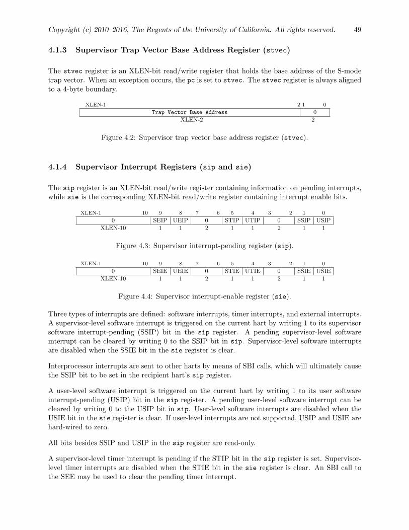
Copyright (c) 2010–2016, The Regents of the University of California. All rights reserved. 49
4.1.3 Supervisor Trap Vector Base Address Register (stvec)
The stvec register is an XLEN-bit read/write register that holds the base address of the S-modetrap vector. When an exception occurs, the pc is set to stvec. The stvec register is always alignedto a 4-byte boundary.
XLEN-1 2 1 0
Trap Vector Base Address 0
XLEN-2 2
Figure 4.2: Supervisor trap vector base address register (stvec).
4.1.4 Supervisor Interrupt Registers (sip and sie)
The sip register is an XLEN-bit read/write register containing information on pending interrupts,while sie is the corresponding XLEN-bit read/write register containing interrupt enable bits.
XLEN-1 10 9 8 7 6 5 4 3 2 1 0
0 SEIP UEIP 0 STIP UTIP 0 SSIP USIP
XLEN-10 1 1 2 1 1 2 1 1
Figure 4.3: Supervisor interrupt-pending register (sip).
XLEN-1 10 9 8 7 6 5 4 3 2 1 0
0 SEIE UEIE 0 STIE UTIE 0 SSIE USIE
XLEN-10 1 1 2 1 1 2 1 1
Figure 4.4: Supervisor interrupt-enable register (sie).
Three types of interrupts are defined: software interrupts, timer interrupts, and external interrupts.A supervisor-level software interrupt is triggered on the current hart by writing 1 to its supervisorsoftware interrupt-pending (SSIP) bit in the sip register. A pending supervisor-level softwareinterrupt can be cleared by writing 0 to the SSIP bit in sip. Supervisor-level software interruptsare disabled when the SSIE bit in the sie register is clear.
Interprocessor interrupts are sent to other harts by means of SBI calls, which will ultimately causethe SSIP bit to be set in the recipient hart’s sip register.
A user-level software interrupt is triggered on the current hart by writing 1 to its user softwareinterrupt-pending (USIP) bit in the sip register. A pending user-level software interrupt can becleared by writing 0 to the USIP bit in sip. User-level software interrupts are disabled when theUSIE bit in the sie register is clear. If user-level interrupts are not supported, USIP and USIE arehard-wired to zero.
All bits besides SSIP and USIP in the sip register are read-only.
A supervisor-level timer interrupt is pending if the STIP bit in the sip register is set. Supervisor-level timer interrupts are disabled when the STIE bit in the sie register is clear. An SBI call tothe SEE may be used to clear the pending timer interrupt.

50 1.9draft: Volume II: RISC-V Privileged Architectures
A user-level timer interrupt is pending if the UTIP bit in the sip register is set. User-level timerinterrupts are disabled when the UTIE bit in the sie register is clear. If user-level interrupts aresupported, the ABI should provide a facility for scheduling timer interrupts in terms of real-timecounter values. If user-level interrupts are not supported, UTIP and UTIE are hard-wired to zero.
A supervisor-level external interrupt is pending if the SEIP bit in the sip register is set. Supervisor-level external interrupts are disabled when the SEIE bit in the sie register is clear. The SBI shouldprovide facilities to mask, unmask, and query the cause of external interrupts.
A user-level external interrupt is pending if the UEIP bit in the sip register is set. User-level ex-ternal interrupts are disabled when the UEIE bit in the sie register is clear. If user-level interruptsare not supported, UEIP and UEIE are hard-wired to zero.
The sip and sie registers are subsets of the mip and mie registers. Reading any field, or writingany writable field, of sip/sie effects a read or write of the homonymous field of mip/mie.
4.1.5 Supervisor Time Register (stime)
Supervisor mode includes a real-time counter, stime, which has 64-bit precision on all RV32, RV64,and RV128 systems. The SBI must provide a facility for determining the timebase of stime, whichmust run at a constant frequency.
XLEN-1 0
stime
XLEN
Figure 4.5: Supervisor time register.
On RV32I only, the stimeh CSR aliases bits 63–32 of stime.
31 0
stimeh
32
Figure 4.6: Upper 32 bits of supervisor time register, RV32 only.
The SBI must provide a facility for scheduling timer interrupts in terms of real-time counter values.
4.1.6 Supervisor Performance Counters (scycle, sinstret)
S-mode includes a basic performance measurement facility. The scycle CSR holds a count of thenumber of cycles the hart has executed since some arbitrary time in the past. The sinstret CSRholds a count of the number of instructions the hart has retired since some arbitrary time in thepast. The scycle and sinstret registers have 64-bit precision on all RV32, RV64, and RV128systems.
On RV32I only, the scycleh and sinstreth CSRs alias bits 63–32 of scycle and sinstret,respectively.

Copyright (c) 2010–2016, The Regents of the University of California. All rights reserved. 51
63 0
scycle
64
Figure 4.7: Supervisor cycle counter.
63 0
sinstret
64
Figure 4.8: Supervisor instructions retired counter.
31 0
scycleh
32
Figure 4.9: Upper 32 bits of supervisor cycle counter, RV32 only.
31 0
sinstreth
32
Figure 4.10: Upper 32 bits of supervisor instructions retired counter, RV32 only.
4.1.7 Supervisor Scratch Register (sscratch)
The sscratch register is an XLEN-bit read/write register, dedicated for use by the supervisor.Typically, sscratch is used to hold a pointer to the hart-local supervisor context while the hart isexecuting user code. At the beginning of a trap handler, sscratch is swapped with a user registerto provide an initial working register.
XLEN-1 0
sscratch
XLEN
Figure 4.11: Supervisor Scratch Register.
4.1.8 Supervisor Exception Program Counter (sepc)
sepc is an XLEN-bit read/write register formatted as shown in Figure 4.12. The low bit of sepc(sepc[0]) is always zero. On implementations that do not support instruction-set extensions with16-bit instruction alignment, the two low bits (sepc[1:0]) are always zero.
When a trap is taken, sepc is written with the virtual address of the instruction that encounteredthe exception.
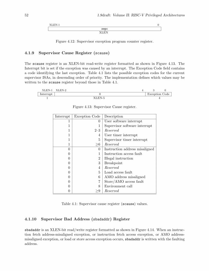
52 1.9draft: Volume II: RISC-V Privileged Architectures
XLEN-1 0
sepc
XLEN
Figure 4.12: Supervisor exception program counter register.
4.1.9 Supervisor Cause Register (scause)
The scause register is an XLEN-bit read-write register formatted as shown in Figure 4.13. TheInterrupt bit is set if the exception was caused by an interrupt. The Exception Code field containsa code identifying the last exception. Table 4.1 lists the possible exception codes for the currentsupervisor ISAs, in descending order of priority. The implementation defines which values may bewritten to the scause register beyond those in Table 4.1.
XLEN-1 XLEN-2 4 3 0
Interrupt 0 Exception Code
1 XLEN-5 4
Figure 4.13: Supervisor Cause register.
Interrupt Exception Code Description
1 0 User software interrupt1 1 Supervisor software interrupt1 2–3 Reserved1 4 User timer interrupt1 5 Supervisor timer interrupt1 ≥6 Reserved
0 0 Instruction address misaligned0 1 Instruction access fault0 2 Illegal instruction0 3 Breakpoint0 4 Reserved0 5 Load access fault0 6 AMO address misaligned0 7 Store/AMO access fault0 8 Environment call0 ≥9 Reserved
Table 4.1: Supervisor cause register (scause) values.
4.1.10 Supervisor Bad Address (sbadaddr) Register
sbadaddr is an XLEN-bit read/write register formatted as shown in Figure 4.14. When an instruc-tion fetch address-misaligned exception, or instruction fetch access exception, or AMO address-misaligned exception, or load or store access exception occurs, sbadaddr is written with the faultingaddress.

Copyright (c) 2010–2016, The Regents of the University of California. All rights reserved. 53
XLEN-1 0
sbadaddr
XLEN
Figure 4.14: Supervisor bad address register.
For instruction fetch access faults on RISC-V systems with variable-length instructions, sbadaddrwill point to the portion of the instruction that caused the fault while sepc will point to thebeginning of the instruction.
4.1.11 Supervisor Page-Table Base Register (sptbr)
The sptbr register is an XLEN-bit read/write register formatted as shown in Figure 4.15. Thesptbr register is only present on systems supporting paged virtual-memory systems. This registerholds the physical page number (PPN) of the root page table, i.e., its supervisor physical addressdivided by 4 KiB. The number of supervisor physical address bits is implementation-defined; anyunimplemented address bits are hard-wired to zero in the sptbr register.
XLEN-1 0
PPN
XLEN
Figure 4.15: Supervisor Page-Table Base Register sptbr.
Storing a PPN in sptbr, rather than a physical address, supports physical address spaces largerthan 2XLEN .
For many applications, the choice of page size has a substantial performance impact. A largepage size increases TLB reach and loosens the associativity constraints on virtually-indexed,physically-tagged caches. At the same time, large pages exacerbate internal fragmentation, wast-ing physical memory and possibly cache capacity.
After much deliberation, we have settled on a conventional page size of 4 KiB for both RV32and RV64. We expect this decision to ease the porting of low-level runtime software and devicedrivers. The TLB reach problem is ameliorated by transparent superpage support in modernoperating systems [2]. Additionally, multi-level TLB hierarchies are quite inexpensive relative tothe multi-level cache hierarchies whose address space they map.
4.1.12 Supervisor Address Space ID Register (sasid)
The sasid register is an ASIDLEN-bit read/write register formatted as shown in Figure 4.16, andis only present on systems supporting paged virtual memory. This register specifies the currentaddress space to facilitate address-translation fences on a per-address-space basis. The SBI shouldprovide a way to obtain ASIDLEN, which is implementation-defined and may be zero if ASIDs arenot supported.

54 1.9draft: Volume II: RISC-V Privileged Architectures
ASIDLEN-1 0
sasid
ASIDLEN
Figure 4.16: Supervisor Address-Space ID Register.
4.2 Supervisor Instructions
In addition to the ECALL, ERET, and EBREAK instructions defined in Section 3.2.1, one newsupervisor-level instruction is provided.
4.2.1 Supervisor Memory-Management Fence Instruction
31 20 19 15 14 12 11 7 6 0
funct12 rs1 funct3 rd opcode
12 5 3 5 7SFENCE.VM vaddr PRIV 0 SYSTEM
The supervisor memory-management fence instruction SFENCE.VM is used to synchronize up-dates to in-memory memory-management data structures with current execution. Instruction exe-cution causes implicit reads and writes to these data structures; however, these implicit referencesare ordinarily not ordered with respect to loads and stores in the instruction stream. Execut-ing an SFENCE.VM instruction guarantees that any stores in the instruction stream prior to theSFENCE.VM are ordered before all implicit references subsequent to the SFENCE.VM. Further-more, executing an SFENCE.VM guarantees that any implicit writes caused by instructions priorto the SFENCE.VM are orderd before all loads and stores subsequent to the SFENCE.VM.
The SFENCE.VM is used to flush any local hardware caches related to address translation. Itis specified as a fence rather than a TLB flush to provide cleaner semantics with respect towhich instructions are affected by the flush operation and to support a wider variety of dynamiccaching structures and memory-management schemes. SFENCE.VM is also used by higherprivilege levels to synchronize page table writes and the address translation hardware.
Note the instruction has no effect on the translations of other RISC-V threads, which must benotified separately. One approach is to use 1) a local data fence to ensure local writes are visibleglobally, then 2) an interprocessor interrupt to the other thread, then 3) a local SFENCE.VMin the interrupt handler of the remote thread, and finally 4) signal back to originating threadthat operation is complete. This is, of course, the RISC-V analog to a TLB shootdown. Alter-natively, implementations might provide direct hardware support for remote TLB invalidation.TLB shootdowns are handled by an SBI call to hide implementation details.
The behavior of SFENCE.VM depends on the current value of the sasid register. If sasid isnonzero, SFENCE.VM takes effect only for address translations in the current address space. Ifsasid is zero, SFENCE.VM affects address translations for all address spaces. In this case, it alsoaffects global mappings, which are described in Section 4.5.1.
The register operand rs1 contains an optional virtual address argument. If rs1=x0, the fence affectsall virtual address translations. For the common case that the translation data structures have only
Copyright (c) 2010–2016, The Regents of the University of California. All rights reserved. 55
been modified for a single address mapping (e.g., one page), rs1 can specify a virtual address withinthat mapping to effect a translation fence for that mapping only.
Simpler implementations can ignore the ASID value in sasid and the virtual address in rs1 andalways perform a global fence.
4.3 Supervisor Operation in Mbare Environment
When the Mbare environment is selected in the VM field of mstatus (Section 3.1.8), supervisor-mode virtual addresses are truncated and mapped directly to supervisor-mode physical addresses.Supervisor physical addresses are then checked using any physical memory protection structures(Section 3.6), before being directly converted to machine-level physical addresses.
4.4 Supervisor Operation in Base and Bounds Environments
When Mbb or Mbbid are selected in the VM field of mstatus (Section 3.1.8), supervisor-modevirtual addresses are translated and checked according to the appropriate machine-level base andbound registers. The resulting supervisor-level physical addresses are then checked using any phys-ical memory protection structures (Section 3.6), before being directly converted to machine-levelphysical addresses.
4.5 Sv32: Page-Based 32-bit Virtual-Memory Systems
When Sv32 is written to the VM field in the mstatus register, the supervisor operates in a 32-bit paged virtual-memory system. Sv32 is supported on RV32 systems and is designed to includemechanisms sufficient for supporting modern Unix-based operating systems.
The initial RISC-V paged virtual-memory architectures have been designed as straightforwardimplementations to support existing operating systems. We have architected page table layoutsto support a hardware page-table walker. Software TLB refills are a performance bottleneck onhigh-performance system, and are especially troublesome with decoupled specialized coprocessors.An implementation can choose to implement software TLB refills using a machine-mode traphandler as an extension to M-mode.
4.5.1 Addressing and Memory Protection
Sv32 implementations support a 32-bit virtual address space, divided into 4 KiB pages. An Sv32virtual address is partitioned into a virtual page number (VPN) and page offset, as shown inFigure 4.17. When Sv32 virtual memory mode is selected in the VM field of the mstatus register,supervisor virtual addresses are translated into supervisor physical addresses via a two-level pagetable. The 20-bit VPN is translated into a 22-bit physical page number (PPN), while the 12-bit page offset is untranslated. The resulting supervisor-level physical addresses are then checked

56 1.9draft: Volume II: RISC-V Privileged Architectures
using any physical memory protection structures (Sections 3.6), before being directly converted tomachine-level physical addresses.
31 22 21 12 11 0
VPN[1] VPN[0] page offset
10 10 12
Figure 4.17: Sv32 virtual address.
33 22 21 12 11 0
PPN[1] PPN[0] page offset
12 10 12
Figure 4.18: Sv32 physical address.
31 20 19 10 9 7 6 5 4 1 0
PPN[1] PPN[0] Reserved for software D R Type V
12 10 3 1 1 4 1
Figure 4.19: Sv32 page table entry.
Sv32 page tables consist of 210 page-table entries (PTEs), each of four bytes. A page table is exactlythe size of a page and must always be aligned to a page boundary. The physical address of the rootpage table is stored in the sptbr register.
The PTE format for Sv32 is shown in Figures 4.19. The V bit indicates whether the PTE is valid;if it is 0, bits 31–1 of the PTE are don’t-cares and may be used freely by software. Otherwise, theType field indicates whether the PTE is a pointer to the next level of the page table or a leaf PTE.If it is the latter, the Type field also encodes the access permissions. Table 4.2 details the Typefield encodings.
An alternative PTE format that orthogonalizes supervisor and user permissions would be easierto explain but would require more bits to encode. This would reduce the amount of physicalmemory that can be addressed with a 32-bit PTE.
Supervisor page mappings may be marked global in the Type field. Global mappings are those thatexist in all address spaces. For non-leaf PTEs, the global setting implies that all mappings in thesubsequent levels of the page table are global. Note that failing to mark a global mapping as globalmerely reduces performance, whereas marking a non-global mapping as global is an error.
Global mappings were devised to reduce the cost of context switches. They need not be flushedfrom an implementation’s address translation caches when an SFENCE.VM instruction is exe-cuted with a nonzero sasid value.
Each leaf PTE maintains a referenced (R) and dirty (D) bit. When a virtual page is read, written,or fetched from, the implementation sets the R bit in the corresponding PTE. When a virtual pageis written, the implementation additionally sets the D bit in the corresponding PTE. The accessthat causes the R and/or D bit to be set must not appear to precede the update of the PTE.Furthermore, the PTE must be updated atomically with respect to other accesses to the PTE.
The R and D bits are never cleared by the implementation. If the supervisor software does not

Copyright (c) 2010–2016, The Regents of the University of California. All rights reserved. 57
Supervisor User
Type Meaning Global R W X R W X
0 Pointer to next level of page table.—
1 Pointer to next level of page table—global mapping. •2 Supervisor read-only, user read-execute page. • • •3 Supervisor read-write, user read-write-execute page. • • • • •4 Supervisor and user read-only page. • •5 Supervisor and user read-write page. • • • •6 Supervisor and user read-execute page. • • • •7 Supervisor and user read-write-execute page. • • • • • •8 Supervisor read-only page. •9 Supervisor read-write page. • •
10 Supervisor read-execute page. • •11 Supervisor read-write-execute page. • • •12 Supervisor read-only page—global mapping. • •13 Supervisor read-write page—global mapping. • • •14 Supervisor read-execute page—global mapping. • • •15 Supervisor read-write-execute page—global mapping. • • • •
Table 4.2: Encoding of PTE Type field.
rely on referenced and/or dirty bits, e.g. if it does not swap pages to secondary storage, it shouldalways set them to 1 in the PTE. The implementation can then avoid issuing memory accessesto set the bits.
Implementations may cause the R bit to be set even when no reference to the page has occurred,provided the page is readable in the current privilege mode. Likewise, implementations may causethe D bit to be set even when no store to the page has occurred, provided the page is writable inthe current privilege mode.
Any level of PTE may be a leaf PTE, so in addition to 4 KiB pages, Sv32 supports 4 MiB megapages.A megapage must be virtually and physically aligned to a 4 MiB boundary.
4.5.2 Virtual Address Translation Process
A virtual address va is translated into a physical address pa as follows:
1. Let a be the value of the sptbr register, and let i = LEVELS−1. (For Sv32, LEVELS equals2.)
2. Let pte be the value of the PTE at address a + va.vpn[i]× PTESIZE. (For Sv32, PTESIZEequals 4.)
3. If pte.v = 0, stop and signal an access fault.
4. Otherwise, pte.v = 1. If pte.type ≥ 2, continue to step 5. Otherwise, this PTE is a pointerto the next level of the page table. Let i = i − 1. If i < 0, stop and signal an access fault.Otherwise, let a = pte.ppn×PAGESIZE and go to step 2. (For Sv32, PAGESIZE equals 212.)

58 1.9draft: Volume II: RISC-V Privileged Architectures
5. A leaf PTE has been found. Determine if the requested memory access is allowed by thepte.type field. If not, stop and signal an access fault. Otherwise, the translation is successful.Set pte.r to 1, and, if the memory access is a store, set pte.d to 1. The translated physicaladdress is given as follows:
• pa.pgoff = va.pgoff.
• If i > 0, then this is a superpage translation and pa.ppn[i− 1 : 0] = va.vpn[i− 1 : 0].
• pa.ppn[LEVELS− 1 : i] = pte.ppn[LEVELS− 1 : i].
4.6 Sv39: Page-Based 39-bit Virtual-Memory System
This section describes a simple paged virtual-memory system designed for RV64 systems, whichsupports 39-bit virtual address spaces. The design of Sv39 follows the overall scheme of Sv32, andthis section details only the differences between the schemes.
4.6.1 Addressing and Memory Protection
Sv39 implementations support a 39-bit virtual address space, divided into 4 KiB pages. An Sv39address is partitioned as shown in Figure 4.20. Load and store effective addresses, which are 64bits, must have bits 63–39 all equal to bit 38, or else an access fault will occur. The 27-bit VPN istranslated into a 38-bit PPN via a three-level page table, while the 12-bit page offset is untranslated.
38 30 29 21 20 12 11 0
VPN[2] VPN[1] VPN[0] page offset
9 9 9 12
Figure 4.20: Sv39 virtual address.
49 30 29 21 20 12 11 0
PPN[2] PPN[1] PPN[0] page offset
20 9 9 12
Figure 4.21: Sv39 physical address.
63 48 47 28 27 19 18 10 9 7 6 5 4 1 0
Reserved PPN[2] PPN[1] PPN[0] Reserved for SW D R Type V
16 20 9 9 3 1 1 4 1
Figure 4.22: Sv39 page table entry.
Sv39 page tables contain 29 page table entries (PTEs), eight bytes each. A page table is exactlythe size of a page and must always be aligned to a page boundary. The physical address of the rootpage table is stored in the sptbr register.
The PTE format for Sv39 is shown in Figure 4.22. Bits 9–0 have the same meaning as for Sv32.Bits 63–48 are reserved for future use and must be zeroed by software for forward compatibility.

Copyright (c) 2010–2016, The Regents of the University of California. All rights reserved. 59
We reserved several PTE bits for a possible extension that improves support for sparse addressspaces by allowing page-table levels to be skipped, reducing memory usage and TLB refill latency.These reserved bits may also be used to facilitate research experimentation. The cost is reducingthe physical address space, but 1 PiB is presently ample. If at some point it no longer suffices,the reserved bits that remain unallocated could be used to expand the physical address space.
Any level of PTE may be a leaf PTE, so in addition to 4 KiB pages, Sv39 supports 2 MiB megapagesand 1 GiB gigapages, each of which must be virtually and physically aligned to a boundary equalto its size.
The algorithm for virtual-to-physical address translation is the same as in Section 4.5.2, exceptLEVELS equals 3 and PTESIZE equals 8.
4.7 Sv48: Page-Based 48-bit Virtual-Memory System
This section describes a simple paged virtual-memory system designed for RV64 systems, whichsupports 48-bit virtual address spaces. Sv48 is intended for systems for which a 39-bit virtualaddress space is insufficient. It closely follows the design of Sv39, simply adding an additional levelof page table, and so this chapter only details the differences between the two schemes.
Implementations that support Sv48 should also support Sv39.
We specified two virtual memory systems for RV64 to relieve the tension between providing alarge address space and minimizing address-translation cost. For many systems, 512 GiB ofvirtual-address space is ample, and so Sv39 suffices. Sv48 increases the virtual address spaceto 256 TiB but increases the physical memory capacity dedicated to page tables, the latency ofpage-table traversals, and the size of hardware structures that store virtual addresses.
Systems that support Sv48 can also support Sv39 at essentially no cost, and so should do soto support supervisor software that assumes Sv39.
4.7.1 Addressing and Memory Protection
Sv48 implementations support a 48-bit virtual address space, divided into 4 KiB pages. An Sv48address is partitioned as shown in Figure 4.23. Load and store effective addresses, which are 64bits, must have bits 63–48 all equal to bit 47, or else an access fault will occur. The 36-bit VPN istranslated into a 38-bit PPN via a four-level page table, while the 12-bit page offset is untranslated.
47 39 38 30 29 21 20 12 11 0
VPN[3] VPN[2] VPN[1] VPN[0] page offset
9 9 9 9 12
Figure 4.23: Sv48 virtual address.
The PTE format for Sv48 is shown in Figure 4.25. Bits 9–0 have the same meaning as for Sv32. Anylevel of PTE may be a leaf PTE, so in addition to 4 KiB pages, Sv48 supports 2 MiB megapages,1 GiB gigapages, and 512 GiB terapages, each of which must be virtually and physically aligned toa boundary equal to its size.

60 1.9draft: Volume II: RISC-V Privileged Architectures
49 39 38 30 29 21 20 12 11 0
PPN[3] PPN[2] PPN[1] PPN[0] page offset
11 9 9 9 12
Figure 4.24: Sv48 physical address.
63 48 47 37 36 28 27 19 18 10 9 7 6 5 4 1 0
Reserved PPN[3] PPN[2] PPN[1] PPN[0] Reserved for SW D R Type V
16 11 9 9 9 3 1 1 4 1
Figure 4.25: Sv48 page table entry.
The algorithm for virtual-to-physical address translation is the same as in Section 4.5.2, exceptLEVELS equals 4 and PTESIZE equals 8.

Chapter 5
Hypervisor-Level ISA
This chapter is a placeholder for a future RISC-V hypervisor-level common core specification.
The privileged architecture is designed to simplify the use of classic virtualization techniques,where a guest OS is run at user-level, as the few privileged instructions can be easily detectedand trapped.
61

62 1.9draft: Volume II: RISC-V Privileged Architectures

Chapter 6
Platform-Level Interrupt Controller(PLIC)
This chapter describes the general architecture for the RISC-V platform-level interrupt controller(PLIC), which prioritizes and distributes global interrupts in a RISC-V system.
6.1 PLIC Overview
Figure 6.1 provides a quick overview of PLIC operation. The PLIC connects global interruptsources, which are usually I/O devices, to interrupt targets, which are usually hart contexts. ThePLIC contains multiple interrupt gateways, one per interrupt source, together with a PLIC corethat performs interrupt prioritization and routing. Global interrupts are sent from their sourceto an interrupt gateway that processes the interrupt signal from each source and sends a singleinterrupt request to the PLIC core, which latches these in the core interrupt pending bits (IP).Each interrupt source is assigned a separate priority. The PLIC core contains a matrix of interruptenable (IE) bits to select the interrupts that are enabled for each target. The PLIC core forwardsan interrupt notification to one or more targets if the targets have any pending interrupts enabled,and the priority of the pending interrupts exceeds a per-target threshold. When the target takesthe external interrupt, it sends an interrupt claim request to retrieve the identifier of the highest-priority global interrupt source pending for that target from the PLIC core, which then clears thecorresponding interrupt source pending bit. After the target has serviced the interrupt, it sendsthe associated interrupt gateway an interrupt completion message and the interrupt gateway cannow forward another interrupt request for the same source to the PLIC. The rest of this chapterdescribes each of these components in detail, though many details are necessarily platform specific.
6.2 Interrupt Sources
RISC-V harts can have both local and global interrupt sources. Only global interrupt sources arehandled by the PLIC.
63

64 1.9draft: Volume II: RISC-V Privileged Architectures
Gateway
PriorityIP
Interrupt Request
Interrupt 2 Signals
Gateway
PriorityIP
Interrupt Request
Interrupt 1 Signals
PLIC Core
PLIC Gateways
0
0 Max IDThresholdMax Pri.
EIP>? EIP Interrupt Notification
Interrupt ID}To Target
0
IE >?
101
01
IE >?
201
01
0
0 Max IDThresholdMax Pri.
EIP>? EIP Interrupt Notification
Interrupt ID}To Target
1
IE >?
101
01
IE >?
201
01
Figure 6.1: Platform-Level Interrupt Controller (PLIC) conceptual block diagram. The figureshows the first two of potentially many interrupt sources, and the first two of potentially manyinterrupt targets. The figure is just intended to show the logic of the PLIC’s operation, not torepresent a realistic implementation strategy.
6.2.1 Local Interrupt Sources
Each hart has a number of local interrupt sources that do not pass through the PLIC, includingthe standard software interrupts and timer interrupts for each privilege level. Local interrupts canbe serviced quickly since there will be minimal latency between the source and the servicing hart,no arbitration is required to determine which hart will service the request, and the servicing hartcan quickly determine the interrupt source using the mcause register.
All local interrupts follow a level-based model, where an interrupt is pending if the correspondingbit in mip is set. The interrupt handler must clear the hardware condition that is causing the mip
bit to be set to avoid retaking the interrupt after re-enabling interrupts on exit from the interrupthandler.
Additional non-standard local interrupt sources can be made visible to machine-mode by addingthem to the high bits of the mip/mie registers, with corresponding additional cause values returned

Copyright (c) 2010–2016, The Regents of the University of California. All rights reserved. 65
in the mcause register. These additional non-standard local interrupts may also be made visibleto lower privilege levels, using the corresponding bits in the mideleg register. The priority of non-standard local interrupt sources relative to external, timer, and software interrupts is platform-specific.
6.2.2 Global Interrupt Sources
Global interrupt sources are those that are prioritized and distributed by the PLIC. Depending onthe platform-specific PLIC implementation, any global interrupt source could be routed to any hartcontext.
Global interrupt sources can take many forms, including level-triggered, edge-triggered, andmessage-signalled. Some sources might queue up a number of interrupt requests. All global inter-rupt sources are converted to a common interrupt request format for the PLIC.
6.3 Interrupt Targets and Hart Contexts
Interrupt targets are usually hart contexts, where a hart context is a given privilege mode on a givenhart (though there are other possible interrupt targets, such as DMA engines). Not all hart contextsneed be interrupt targets, in particular, if a processor core does not support delegating externalinterrupts to lower-privilege modes, then the lower-privilege hart contexts will not be interrupttargets. Interrupt notifications generated by the PLIC appear in the meip/heip/seip/ueip bits ofthe mip/hip/sip/uip registers for M/H/S/U modes respectively. The notifications only appear inlower-privilege xip registers if external interrupts have been delegated to the lower-privilege modes.
Each processor core must define a policy on how simultaneous active interrupts are taken bymultiple hart contexts on the core. For the simple case of a single stack of hart contexts, one foreach supported privileged mode, interrupts for higher-privilege contexts can preempt execution ofinterrupt handlers for lower-privilege contexts. A multithreaded processor code could run multipleindependent interrupt handlers on different hart contexts at the same time. A processor core couldalso provide hart contexts that are only used for interrupt handling to reduce interrupt servicelatency, and these might preempt interrupt handlers for other harts on the same core.
The PLIC treats each interrupt target independently and does not take into account any interruptprioritization scheme used by a component that contains multiple interrupt targets. As a result,the PLIC provides no concept of interrupt preemption or nesting so this must be handled by thecores hosting multiple interrupt target contexts.
6.4 Interrupt Gateways
The interrupt gateways are responsible for converting global interrupt signals into a common inter-rupt request format, and for controlling the flow of interrupt requests to the PLIC core. At mostone interrupt request per interrupt source can be pending in the PLIC core at any time, indicatedby setting the source’s IP bit. The gateway only forwards a new interrupt request to the PLIC

66 1.9draft: Volume II: RISC-V Privileged Architectures
core after receiving notification that the interrupt handler servicing the previous interrupt requestfrom the same source has completed.
If the global interrupt source uses level-sensitive interrupts, the gateway will convert the firstassertion of the interrupt level into an interrupt request, but thereafter the gateway will not forwardan additional interrupt request until it receives an interrupt completion message. On receiving aninterrupt completion message, if the interrupt is level-triggered and the interrupt is still asserted, anew interrupt request will be forwarded to the PLIC core. The gateway does not have the facilityto retract an interrupt request once forwarded to the PLIC core. If a level-sensitive interrupt sourcedeasserts the interrupt after the PLIC core accepts the request and before the interrupt is serviced,the interrupt request remains present in the IP bit of the PLIC core and will be serviced by ahandler, which will then have to determine that the interrupt device no longer requires service.
If the global interrupt source was edge-triggered, the gateway will convert the first matching signaledge into an interrupt request. Depending on the design of the device and the interrupt handler,inbetween sending an interrupt request and receiving notice of its handler’s completion, the gatewaymight either ignore additional matching edges or increment a counter of pending interrupts. Ineither case, the next interrupt request will not be forwarded to the PLIC core until the previouscompletion message has been received. If the gateway has a pending interrupt counter, the counterwill be decremented when the interrupt request is accepted by the PLIC core.
Unlike dedicated-wire interrupt signals, message-signalled interrupts (MSIs) are sent over the sys-tem interconnect via a message packet that describes which interrupt is being asserted. The messageis decoded to select an interrupt gateway, and the relevant gateway then handles the MSI similarto an edge-triggered interrupt.
6.5 Interrupt Identifiers (IDs)
Global interrupt sources are assigned small unsigned integer identifiers, beginning at the value 1.An interrupt ID of 0 is reserved to mean “no interrupt”.
Interrupt identifiers are also used to break ties when two or more interrupt sources have the sameassigned priority. Smaller values of interrupt ID take precedence over larger values of interrupt ID.
6.6 Interrupt Priorities
Interrupt priorities are small unsigned integers, with a platform-specific maximum number of sup-ported levels. The priority value 0 is reserved to mean “never interrupt”, and interrupt priorityincreases with increasing integer values.
Each global interrupt source has an associated interrupt priority held in a platform-specific memory-mapped register. Different interrupt sources need not support the same set of priority values. Avalid implementation can hardwire all input priority levels. Interrupt source priority registersshould be RLWA fields to allow software to determine the number and position of read-write bitsin each priority specification, if any. To simplify discovery of supported priority values, each priority

Copyright (c) 2010–2016, The Regents of the University of California. All rights reserved. 67
register must support any combination of values in the bits that are variable within the register,i.e., if there are two variable bits in the register, all four combinations of values in those bits mustoperate as valid priority levels.
In the degenerate case, all priorities can be hardwired to the value 1, in which case input prioritiesare effectively determined by interrupt ID.
The supported priority values can be determined as follows: 1) write all zeros to the priorityregister then 2) read back the value. Any set bits are hardwired to 1. Next, 3) write all onesto the register, and 4) read back the value. Any clear bits are hardwired to 0. Any set bits thatwere not found to be hardwired in step 2 are variable. The supported priority levels are the setof values obtained by substituting all combinations of ones and zeros in the variable bits withinthe priority field.
6.7 Interrupt Enables
Each target has a vector of interrupt enable (IE) bits, one per interrupt source. The target willnot receive interrupts from sources that are disabled. The IE bits for a single target should bepacked together as a bit vector in platform-specific memory-mapped control registers to supportrapid context switching of the IE bits for a target. IE bits are RLWA fields that can be hardwiredto either 0 or 1.
A large number of potential IE bits might be hardwired to zero in cases where some interruptsources can only be routed to a subset of targets.
A larger number of bits might be wired to 1 for an embedded device with fixed interrupt rout-ing. Interrupt priorities, thresholds, and hart-internal interrupt masking provide considerableflexibility in ignoring external interrupts even if a global interrupt source is always enabled.
6.8 Interrupt Priority Thresholds
Each interrupt target has an associated priority threshold, held in a platform-specific memory-mapped register. Only active interrupts that have a priority strictly greater than the thresholdwill cause a interrupt notification to be sent to the target. Different interrupt targets need notsupport the same set of priority threshold values. Interrupt target threshold registers should beRLWA fields to allow software to determine the supported thresholds. A threshold register shouldalways be able to hold the value zero, in which case, no interrupts are masked. If implemented,the threshold register will usually also be able to hold the maximum priority level, in which caseall interrupts are masked.
A simple valid implementation is to hardwire the threshold to zero, in which case it has no effect,and the individual enable bits will have to be saved and restored to attain the same effect. Whilethe function of the threshold can be achieved by changing the interrupt-enable bits, manipulatinga single threshold value avoids the target having to consider the individual priority levels of eachinterrupt source, and saving and restoring all the interrupt enables. Changing the thresholdquickly might be especially important for systems that move frequently between power states.
68 1.9draft: Volume II: RISC-V Privileged Architectures
6.9 Interrupt Notifications
Each interrupt target has an external interrupt pending (EIP) bit in the PLIC core that indicatesthat the corresponding target has a pending interrupt waiting for service. The value in EIP canchange as a result of changes to state in the PLIC core, brought on by interrupt sources, interrupttargets, or other agents manipulating register values in the PLIC. The value in EIP is communicatedto the destination target as an interrupt notification. If the target is a RISC-V hart context, theinterrupt notifications arrive on the meip/heip/seip/ueip bits depending on the privilege level ofthe hart context.
In simple systems, the interrupt notifications will be simple wires connected to the processorimplementing a hart. In more complex platforms, the notifications might be routed as messagesacross a system interconnect.
The PLIC hardware only supports multicasting of interrupts, such that all enabled targets willreceive interrupt notifications for a given active interrupt.
Multicasting provides rapid response since the fastest responder claims the interrupt, but can bewasteful in high-interrupt-rate scenarios if multiple harts take a trap for an interrupt that onlyone can successfully claim. Software can modulate the PLIC IE bits as part of each interrupthandler to provide alternate policies, such as interrupt affinity or round-robin unicasting.
Depending on the platform architecture and the method used to transport interrupt notifications,these might take some time to be received at the targets. The PLIC is guaranteed to eventuallydeliver all state changes in EIP to all targets, provided there is no intervening activity in the PLICcore.
The value in an interrupt notification is only guaranteed to hold an EIP value that was valid atsome point in the past. In particular, a second target can respond and claim an interrupt whilea notification to the first target is still in flight, such that when the first target tries to claim theinterrupt it finds it has no active interrupts in the PLIC core.
6.10 Interrupt Claims
Sometime after a target receives an interrupt notification, it might decide to service the interrupt.The target sends an interrupt claim message to the PLIC core, which will usually be implementedas a non-idempotent memory-mapped I/O control register read. On receiving a claim message, thePLIC core will atomically determine the ID of the highest-priority pending interrupt for the targetand then clear down the corresponding source’s IP bit. The PLIC core will then return the ID tothe target. The PLIC core will return an ID of zero, if there were no pending interrupts for thetarget when the claim was serviced.
After the highest-priority pending interrupt is claimed by a target and the corresponding IP bitis cleared, other lower-priority pending interrupts might then become visible to the target, andso the PLIC EIP bit might not be cleared after a claim. The interrupt handler can check thelocal meip/heip/seip/ueip bits before exiting the handler, to allow more efficient service of otherinterrupts without first restoring the interrupted context and taking another interrupt trap.

Copyright (c) 2010–2016, The Regents of the University of California. All rights reserved. 69
It is always legal for a hart to perform a claim even if the EIP is not set. In particular, a hart couldset the threshold value to maximum to disable interrupt notifications and instead poll for activeinterrupts using periodic claim requests, though a simpler approach to implement polling would beto clear the external interrupt enable in the corresponding xie register for privilege mode x.
6.11 Interrupt Completion
After a handler has completed service of an interrupt, the associated gateway must be sent aninterrupt completion message, usually as a write to a non-idempotent memory-mapped I/O controlregister. The gateway will only forward additional interrupts to the PLIC core after receiving thecompletion message.
6.12 Interrupt Flow
Figure 6.2 shows the messages flowing between agents when handling interrupts via the PLIC.
Interrupt Source Gateway
PLIC Core Target
Interrupt Request
Interrupt Notification
Interrupt Claim
Claim Response
Interrupt Signalled
Interrupt Completion
Next Request
}Handler Running
Figure 6.2: Flow of interrupt processing via the PLIC.
The gateway will only forward a single interrupt request at a time to the PLIC, and not forwardsubsequent interrupts requests until an interrupt completion is received. The PLIC will set the IPbit once it accepts an interrupt request from the gateway, and sometime later forward an interruptnotification to the target. The target might take a while to respond to a new interrupt arriving,

70 1.9draft: Volume II: RISC-V Privileged Architectures
but will then send an interrupt claim request to the PLIC core to obtain the interrupt ID. ThePLIC core will atomically return the ID and clear the corresponding IP bit, after which no othertarget can claim the same interrupt request. Once the handler has processed the interrupt, it sendsan interrupt completion message to the gateway to allow a new interrupt request.
6.13 PLIC Core Specification
The operation of the PLIC core can be specified as a non-deterministic finite-state machine withinput and output messsage queues, with the following atomic actions:
• Write Register: A message containing a register write request is dequeued. One of theinternal registers is written, where an internal register can be a priority, an interrupt-enable(IE), or a threshold.
• Accept Request: If the IP bit corresponding to the interrupt source is clear, a messagecontaining an interrupt request from a gateway is dequeued and the IP bit is set.
• Process Claim: An interrupt claim message is dequeued. A claim-response message isenqueued to the requester with the ID of the highest-priority active interrupt for that target,and the IP bit corresponding to this interrupt source is cleared.
The value in the EIP bit is determined as a combinational function of the PLIC Core state. Interruptnotifications are sent via an autonomous process that ensures the EIP value is eventually reflectedat the target.
Note that the operation of the interrupt gateways is decoupled from the PLIC core. A gatewaycan handle parsing of interrupt signals and processing interrupt completion messages concurrentlywith other operations in the PLIC core.
Figure 6.1 is a high-level conceptual view of the PLIC design. The PLIC core can be implementedin many ways provided its behavior can always be understood as following from some sequentialordering of these atomic actions. In particular, the PLIC might process multiple actions in asingle clock cycle, or might process each action over many clock cycles.
6.14 Controlling Access to the PLIC
In the expected use case, only machine mode accesses the source priority, source pending, andtarget interrupt enables to configure the interrupt subsystem. Lower-privilege modes access thesefeatures via ABI, SBI, or HBI calls. The interrupt enables act as a protection mechanism where atarget can only signal completion to an interrupt gateway that is currently enabled for that target.
Interrupt handlers that run with lower than machine-mode privilege need only be able to performa claim read and a completion write, and to set their target threshold value. The memory map forthese registers should allow machine mode to protect different targets from each other’s accesses,using either physical memory protection or virtual memory page protections.

Chapter 7
RISC-V Privileged Instruction SetListings
This chapter presents instruction set listings for all instructions defined in the RISC-V PrivilegedArchitecture.
71

72 1.9draft: Volume II: RISC-V Privileged Architectures
31 27 26 25 24 20 19 15 14 12 11 7 6 0
imm[11:0] rs1 funct3 rd opcode I-type
Instructions to Access CSRscsr rs1 001 rd 1110011 CSRRWcsr rs1 010 rd 1110011 CSRRScsr rs1 011 rd 1110011 CSRRCcsr zimm 101 rd 1110011 CSRRWIcsr zimm 110 rd 1110011 CSRRSIcsr zimm 111 rd 1110011 CSRRCI
Instructions to Change Privilege Level000000000000 00000 000 00000 1110011 ECALL000000000001 00000 000 00000 1110011 EBREAK000000000010 00000 000 00000 1110011 URET000100000010 00000 000 00000 1110011 SRET001000000010 00000 000 00000 1110011 HRET001100000010 00000 000 00000 1110011 MRET
Interrupt-Management Instructions000100000101 00000 000 00000 1110011 WFI
Memory-Management Instructions000100000100 rs1 000 00000 1110011 SFENCE.VM
Table 7.1: RISC-V Privileged Instructions

Chapter 8
Machine Configuration Strings
RISC-V platforms may contain myriad devices, processor cores, and configuration parameters. Tosupport standard software tools across a diversity of platforms, the RISC-V privileged architecturerecommends a single, standard textual format to describe the platform and the components therein,including their identity, location in the memory map, and static configuration parameters. Thisconfiguration string should be made accessible to both external debuggers and to trusted software.The machine configuration string lives in read-only physical memory that must be directly accessibleafter reset. The platform will describe how to locate this string.
The configuration string is a sequence of key-value pairs, where the values may be nested sequencesof key-value pairs. To ease debugging, it is encoded in a human-readable format as a single null-terminated UTF-8 string. Keys comprise most printable characters (including ASCII 35–58 and60–122 and printable UTF-8 characters). Values are whitespace-delimited sequences of the followingthree types: character sequences drawn from the space of legal keys; arbitrary strings enclosed indouble-quotes; and nested sequences of key-value pairs enclosed in {braces}. Values are terminatedwith a semicolon.
Quoted strings may contain ASCII characters 32–33 and 35–126 and other printable UTF-8 char-acters. Literal double-quotes and unprintable characters can be encoded in quoted strings with theC-style escape sequence \xhh, e.g., \x22 for double-quotes or \x09 for a horizontal tab.
By convention, comments may be encoded as key-value pairs with a key of #, e.g. # this is a
comment;.
The configuration string does not expressly encode types, as the consumer of a value should knowhow to interpret it. In particular, the format does not distinguish between numerical types andcharacter sequences. We recommend a standard encoding of arbitrary-precision numerical types:
1. Decimal integers are encoded as when written in English: as a sequence of the characters 0–9,optionally preceded by a hyphen for negation, e.g. 123 or -420.
2. Decimal reals are encoded like floating-point literals in C source code, e.g., -1. or 6.022e23.
3. Hexadecimal integers are encoded like C integer literals: 0x followed by a sequence of 0–9,a–f, A–F, and underscores, optionally preceded by a hyphen for negation, e.g. 0xdeadBEEF or
73

74 1.9draft: Volume II: RISC-V Privileged Architectures
-0x1. Underscores are used to improve readability of long constants, e.g., 0x 0001 0000 0000
and 0x100000000 are equivalent.
4. Arbitrary byte sequences may be base-64-encoded by representing every six consecutive bitsin the input, in little-endian order, as one byte in the encoded format. Input patterns 0–63correspond to ASCII 48–111 in the encoding. The patten is preceded with the prefix 0z. Forexample, abcd is encoded as 0zQ9fHT1.
A sample configuration string follows.
vendor ucberkeley,20151105;
n-cpus 3;
n-harts 4;
cpu-0 {
isa rv64g;
n-harts 2;
harts 0xf0000000 0xf0010000;
};
cpu-1 {
isa rv32i;
n-harts 2;
harts 0xf0020000 0xf0030000;
};
cpu-2 {
isa sparcv8; # legacy;
};
foo {
max-voltage 1.0;
bar {
baz "quux {xyzzy}";
} {
garply waldo "edgar" fred;
};
};
To save space, the same configuration string may be encoded as:
TODO

Chapter 9
History
Acknowledgments
Thanks to Ruslan Bukin, Christopher Celio, David Chisnall, Palmer Dabbelt, Dennis Ferguson,Mike Frysinger, Rishiyur Nikhil, Albert Ou, John Ousterhout, Colin Schmidt, Matt Thomas,Tommy Thorn, Ray VanDeWalker, and Reinoud Zandijk for feedback on the privileged specifi-cation.
9.1 Funding
Development of the RISC-V architecture and implementations has been partially funded by thefollowing sponsors.
• Par Lab: Research supported by Microsoft (Award #024263) and Intel (Award #024894)funding and by matching funding by U.C. Discovery (Award #DIG07-10227). Additionalsupport came from Par Lab affiliates Nokia, NVIDIA, Oracle, and Samsung.
• Project Isis: DoE Award DE-SC0003624.
• ASPIRE Lab: DARPA PERFECT program, Award HR0011-12-2-0016. DARPA POEMprogram Award HR0011-11-C-0100. The Center for Future Architectures Research (C-FAR),a STARnet center funded by the Semiconductor Research Corporation. Additional sup-port from ASPIRE industrial sponsor, Intel, and ASPIRE affiliates, Google, Huawei, Nokia,NVIDIA, Oracle, and Samsung.
The content of this paper does not necessarily reflect the position or the policy of the US governmentand no official endorsement should be inferred.
75

76 1.9draft: Volume II: RISC-V Privileged Architectures

Bibliography
[1] Robert P. Goldberg. Survey of virtual machine research. Computer, 7(6):34–45, June 1974.
[2] Juan Navarro, Sitararn Iyer, Peter Druschel, and Alan Cox. Practical, transparent operatingsystem support for superpages. SIGOPS Oper. Syst. Rev., 36(SI):89–104, December 2002.
[3] Rusty Russell. Virtio: Towards a de-facto standard for virtual I/O devices. SIGOPS Oper.Syst. Rev., 42(5):95–103, July 2008.
77