Embed Size (px)
Citation preview
The Results of TGFs and
TLEs Observations in
RELEC Experiment on board
Vernov Space Mission
“Skobel’tsyn Institute of Nuclear Physics of Lomonosov
Moscow State University
“S.A.Lavochkin” Scientific and Production Association.,
Russia
Space Research Institute, Russia
NILAKT, Russia
Etvosh University, Hungary
Sungkyunkwan University (SKKU)., Seoul, Korea
Space Research Centrum, Poland Academy of Sciences,
Poland
Lvov Center of Space Research Institute, Ukraine
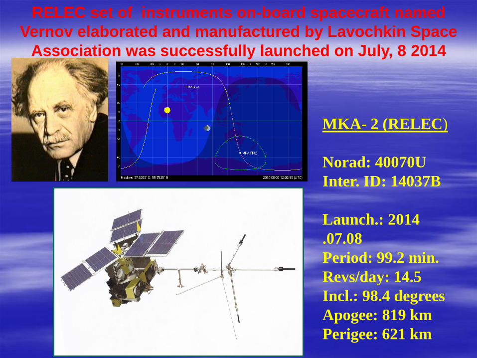
RELEC set of instruments on-board spacecraft named
Vernov elaborated and manufactured by Lavochkin Space
Association was successfully launched on July, 8 2014
MKA- 2 (RELEC)
Norad: 40070U
Inter. ID: 14037B
Launch.: 2014
.07.08
Period: 99.2 min.
Revs/day: 14.5
Incl.: 98.4 degrees
Apogee: 819 km
Perigee: 621 km
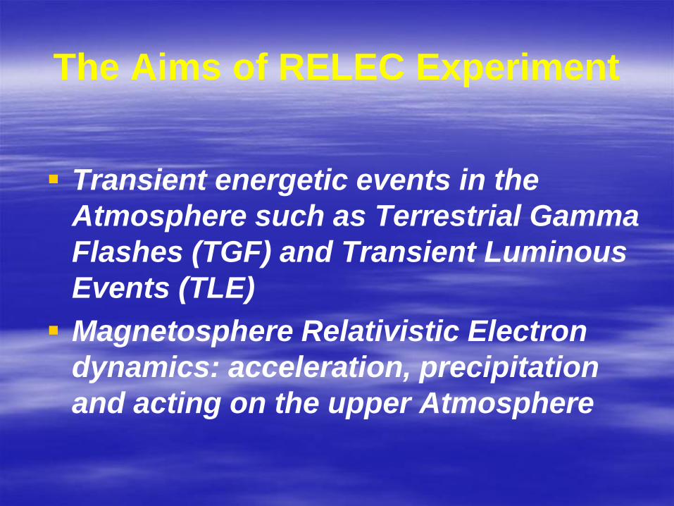
The Aims of RELEC Experiment
Transient energetic events in the
Atmosphere such as Terrestrial Gamma
Flashes (TGF) and Transient Luminous
Events (TLE)
Magnetosphere Relativistic Electron
dynamics: acceleration, precipitation
and acting on the upper Atmosphere

Instruments and Collaboration
DRGE-1 & DRGE-2 - two identical detectors of X-,
gamma-rays and high-energy electrons of high temporal
resolution and sensitivity (SINP MSU)
DRGE-3 - three axe directed detectors of energetic
electrons and protons (SINP MSU)
Telescope-T (MTEL-2) - optical imager (SINP MSU,
Korea)
DUF - UV detector (SINP MSU)
NChA (LFA) - low-frequency analyser (Space Res. Inst.
RAS, Etvos Univ., Hungary, Lviv Space Center, Ukraine)
RChA (RFA) - radio-frequency analyser (Space Res. Inst.
RAS, Space Center, Poland)
BE - module of commands and data collection (NILAKT)

Instrument DRGE is a complex of scintillator detectors for
study of x-rays, gamma-rays and electrons.
Two parts of the instrument
DRGE-1, DRGE-2 DRGE-3
X-rays and gammas in 0.01-
3 MeV energy range from
atmospheric discharges with
high time resolution (up to
15us)
Electrons in 3 orthogonal
directions, secondary x-rays
and gammas produced by
electrons.
DRGE design
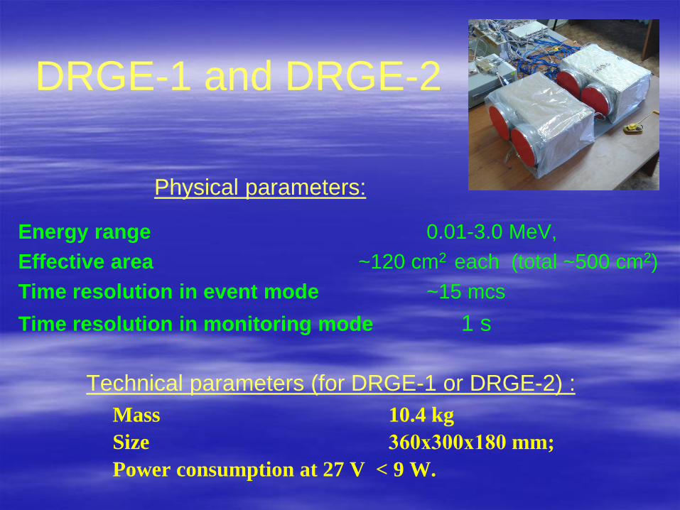
DRGE-1 and DRGE-2
Physical parameters:
Energy range 0.01-3.0 MeV,
Effective area ~120 cm2 each (total ~500 cm2)
Time resolution in event mode ~15 mcs
Time resolution in monitoring mode 1 s
Technical parameters (for DRGE-1 or DRGE-2) :
Mass 10.4 kg
Size 360х300х180 mm;
Power consumption at 27 V < 9 W.
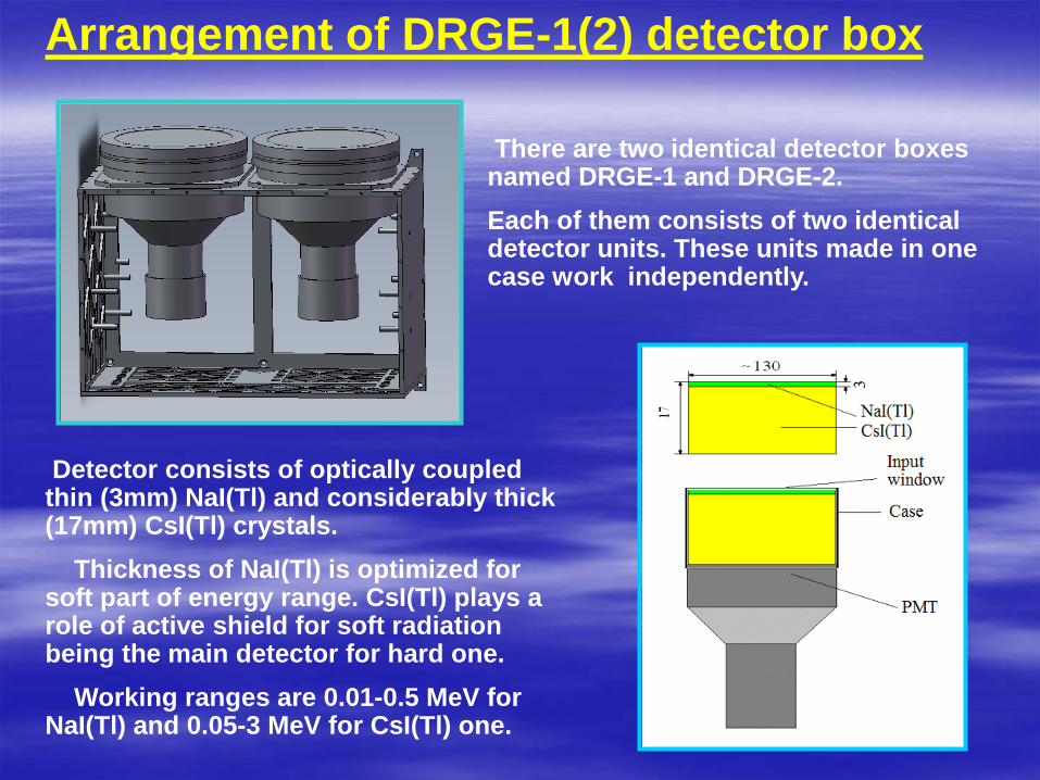
Arrangement of DRGE-1(2) detector box
Detector consists of optically coupled thin (3mm) NaI(Tl) and considerably thick (17mm) CsI(Tl) crystals.
Thickness of NaI(Tl) is optimized for soft part of energy range. CsI(Tl) plays a role of active shield for soft radiation being the main detector for hard one.
Working ranges are 0.01-0.5 MeV for NaI(Tl) and 0.05-3 MeV for CsI(Tl) one.
There are two identical detector boxes named DRGE-1 and DRGE-2.
Each of them consists of two identical detector units. These units made in one case work independently.
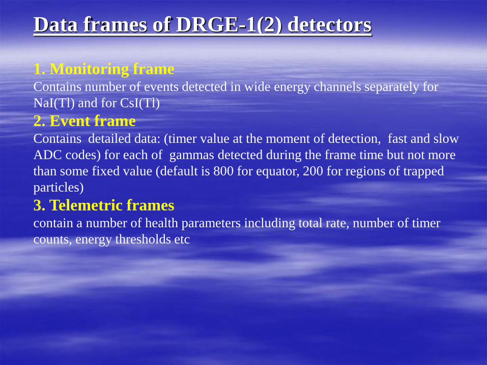
Data frames of DRGE-1(2) detectors
1. Monitoring frame Contains number of events detected in wide energy channels separately for
NaI(Tl) and for CsI(Tl)
2. Event frame Contains detailed data: (timer value at the moment of detection, fast and slow
ADC codes) for each of gammas detected during the frame time but not more
than some fixed value (default is 800 for equator, 200 for regions of trapped
particles)
3. Telemetric frames contain a number of health parameters including total rate, number of timer
counts, energy thresholds etc

To the sky
Scintillation detectors of DRGE-3
Along the geomagnetic
field line
Three identical BGO/CsI(Tl)/plastic
scintillator phosvich detectors are
directed along three axe mutually
normal (as Cartesian coordinate
system)
Detector consists of optically coupled thin (3mm) CsI(Tl) and considerably thick (17mm) BGO crystals with 20mm. Surrounding plastic scintillator is 5mm thick. FOV is formed by cylindrical collimator made of 1mm Cu.

DRGE-3 Physical parameters:
electrons protons
energy range 0.1-15.0 MeV, 1.0-100.0 MeV
geom. factor ~2 cm2sr ~2 cm2sr
temporal resolution 15.5 mcs 15.5 mcs
sensitivity ~10 part./cm2s ~10 part./cm2s
Technical parameters
Mass 2.8 kg;
sizes 245х160х180 mm;
power consumption at 27 V 7 W.

1.Signal revealing algorithm, which selects the brightest flashes in every 5 s time
interval.
2. Gain control algorithm for fixing PMT anode current across whole airglow
range.
3.Interface algorithm for communication with the satellite board.
4.Waveform saving algorithm for storage waveforms of the flashes in digital
form.
Block diagram of the detector (1) collimator, (2) UV-1 filter, (3) IR filter, MX-multiplexor , HV- PMT high voltage source, ADC and DAC—analog to digital and
digital to analog convertors, Logic Unit-FPGA.
DUV - detector UV – 240-400nm weigh– 0.5 kg
IR – 610-800nm power consumption – 2.5W
Sensitive - area 0.4cm2 gain control range – 106
Field of view ~ 200 waveform window amplitude range
4x10³
Full dynamic range- 4x 10⁹ nadir observation
Maximum sensitivity -one photoelectron
Waveform window
DUV instrument

Telescope –T (Mtel-2) instrument
Optical imager based on multi-grain mirror
Physical parameters:
Technical parameters
Mass - < 5 kg;
sizes 200200400 mm;
power expenditure at 28 V
no more 6 W.
Spectral band: 300-400 nm
Angle resolution: 0.4o.
Angle of view: 7.5o.
Cells number: 4000.
Photomultiplier channels
number: 64.
Time resolution: 100 s.
Amplitude range: 105.

NChA instrumentNChA instrumentLow-frequency analyzer: two magnetic field componentLow-frequency analyzer: two magnetic field component
meters, two electric field component meters andmeters, two electric field component meters and
analyzer unitanalyzer unit
Physical parameters:Physical parameters:
Technical parameters
Mass - < 3 kg;
sizes 16013080 mm;
power expenditure at 28 V
no more 5 W.
Frequency band: 20 Hz - 20 kHz
number of spectral components:
1024
frequency step: 20 Hz .
Time resolution: 2 s.
Number of spectral componentcategories: 16.
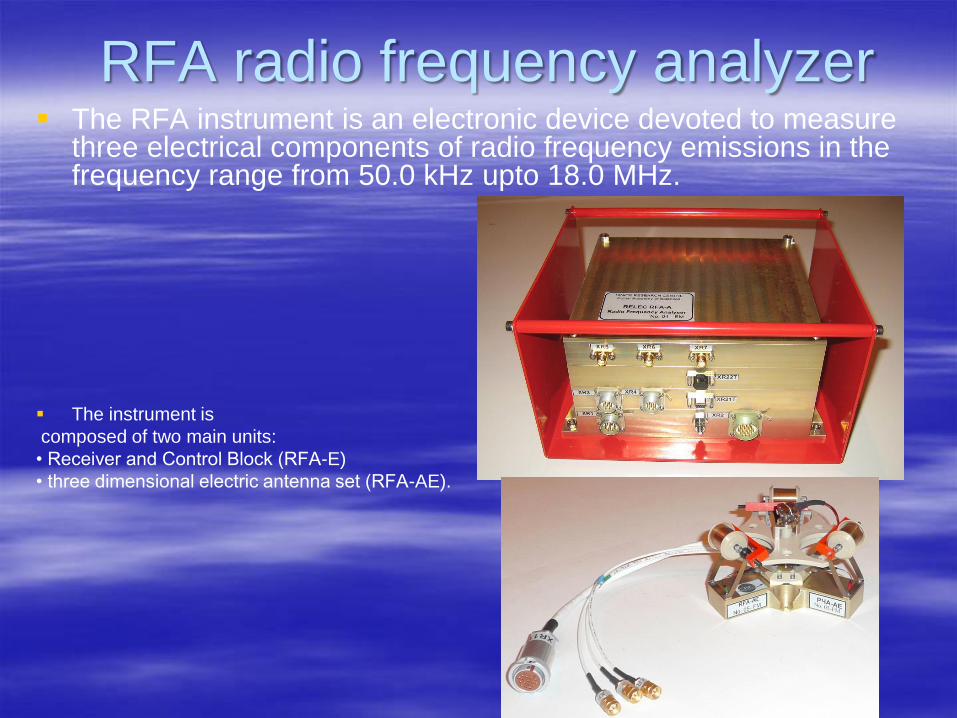
RFA radio frequency analyzer The RFA instrument is an electronic device devoted to measure
three electrical components of radio frequency emissions in the frequency range from 50.0 kHz upto 18.0 MHz.
The instrument is
composed of two main units:
• Receiver and Control Block (RFA-E)
• three dimensional electric antenna set (RFA-AE).
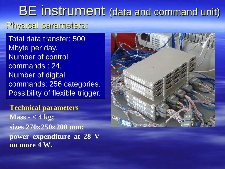
BE instrument (data and command unit)
Physical parameters:
Technical parameters
Mass - < 4 kg;
sizes 270250200 mm;
power expenditure at 28 V
no more 4 W.
Total data transfer: 500
Mbyte per day.
Number of control
commands : 24.
Number of digital
commands: 256 categories.
Possibility of flexible trigger.
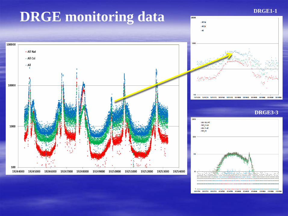
DRGE monitoring data DRGE1-1
DRGE3-3
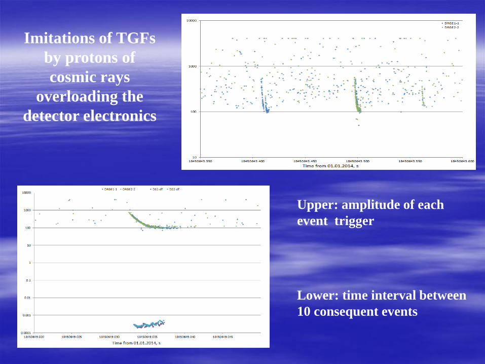
Imitations of TGFs
by protons of
cosmic rays
overloading the
detector electronics
Upper: amplitude of each
event trigger
Lower: time interval between
10 consequent events
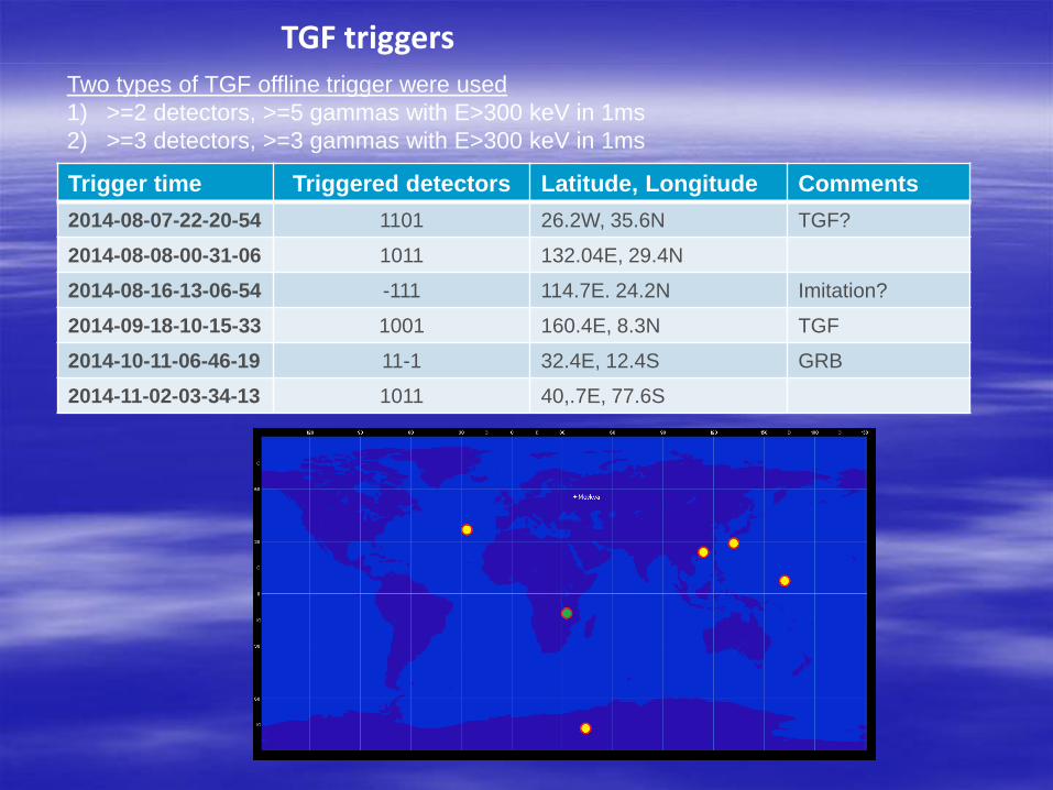
Trigger time Triggered detectors Latitude, Longitude Comments
2014-08-07-22-20-54 1101 26.2W, 35.6N TGF?
2014-08-08-00-31-06 1011 132.04E, 29.4N
2014-08-16-13-06-54 -111 114.7E. 24.2N Imitation?
2014-09-18-10-15-33 1001 160.4E, 8.3N TGF
2014-10-11-06-46-19 11-1 32.4E, 12.4S GRB
2014-11-02-03-34-13 1011 40,.7E, 77.6S
TGF triggers Two types of TGF offline trigger were used
1) >=2 detectors, >=5 gammas with E>300 keV in 1ms
2) >=3 detectors, >=3 gammas with E>300 keV in 1ms
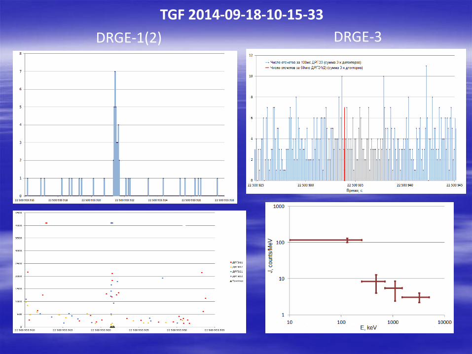
TGF 2014-09-18-10-15-33
DRGE-1(2) DRGE-3
Sum for 50mcs
Detected gammas

Examples of oscillogram of five different types of flashes detected in experiment
1- low amplitude noise like signals. 2- high latitudes flashes. 3- UV- blue flashes (UV/IR>10).
4 – UV & IR signals from lighting. 5- mixed UV&IR signals from lightning and blue flash
1 2 3
4 5
variety of the flashes
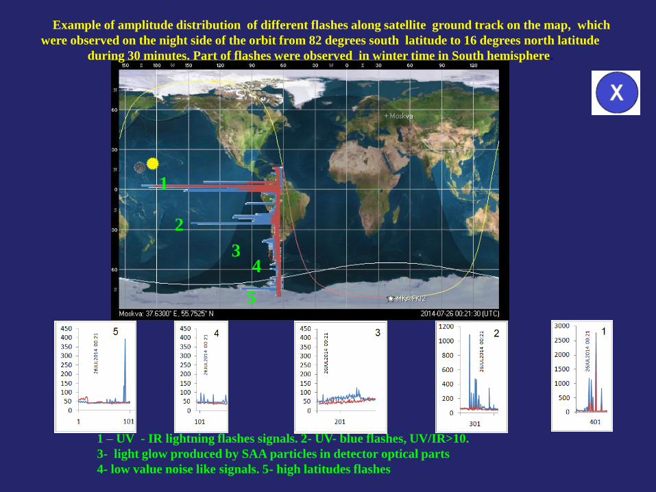
1 – UV - IR lightning flashes signals. 2- UV- blue flashes, UV/IR>10.
3- light glow produced by SAA particles in detector optical parts
4- low value noise like signals. 5- high latitudes flashes
1
2
3 4
5
Example of amplitude distribution of different flashes along satellite ground track on the map, which
were observed on the night side of the orbit from 82 degrees south latitude to 16 degrees north latitude
during 30 minutes. Part of flashes were observed in winter time in South hemisphere.

‘Series’ of flashes detected above Africa
during one orbit
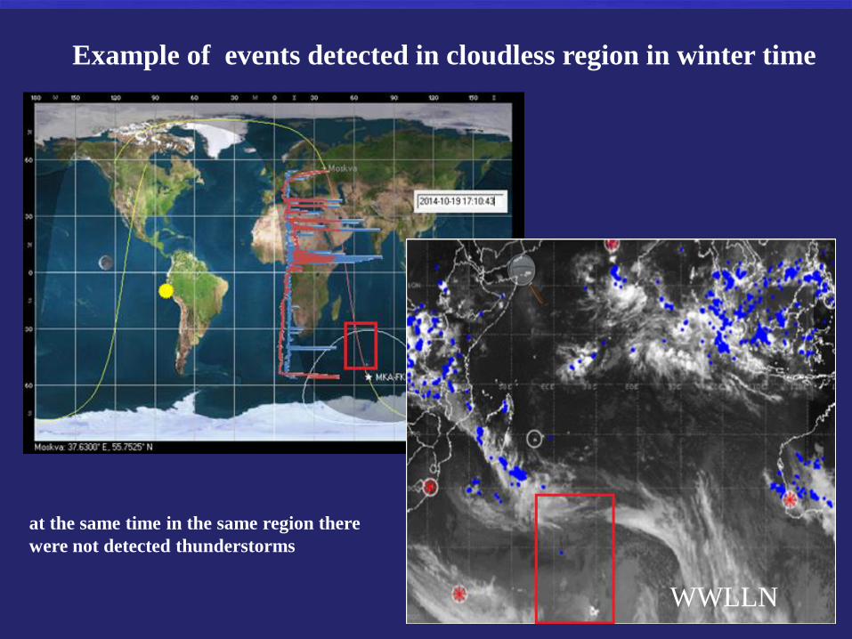
Example of events detected in cloudless region in winter time
WWLLN
at the same time in the same region there
were not detected thunderstorms
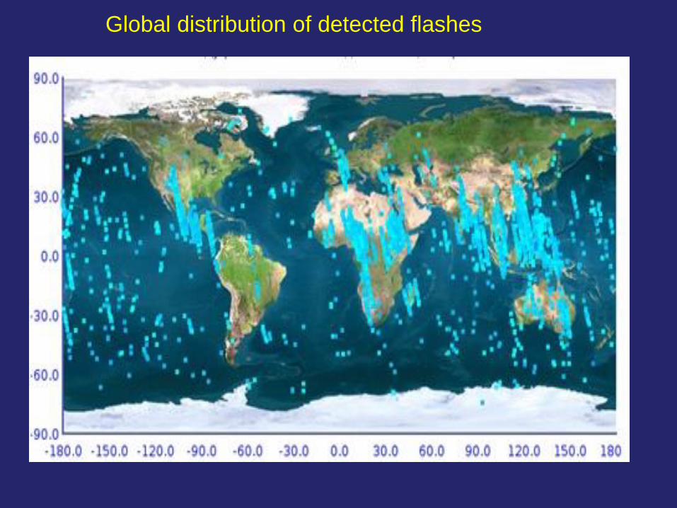
Global distribution of detected flashes
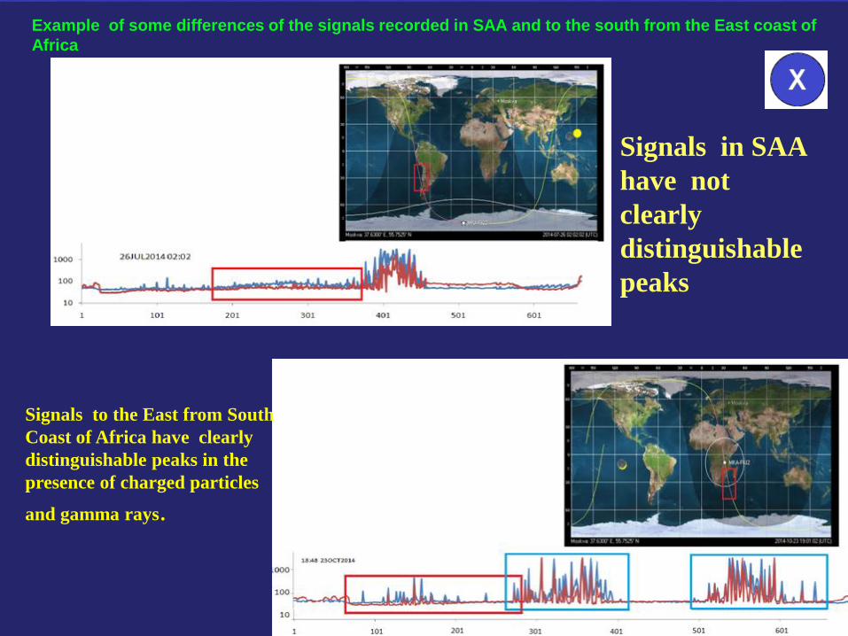
Example of some differences of the signals recorded in SAA and to the south from the East coast of
Africa
Signals to the East from South
Coast of Africa have clearly
distinguishable peaks in the
presence of charged particles
and gamma rays.
Signals in SAA
have not
clearly
distinguishable
peaks


Thank You!