Embed Size (px)
Citation preview

The Residences at Christina Landing
Food Sciences Building
Pamela A. MorrisStructural Emphasis
Wilmington, DE
Renderings provided by KLING
AE Senior ThesisApril 12, 2005

Acknowledgements
The Buccini / Pollin Group
The Gilbane Building Company
Kling

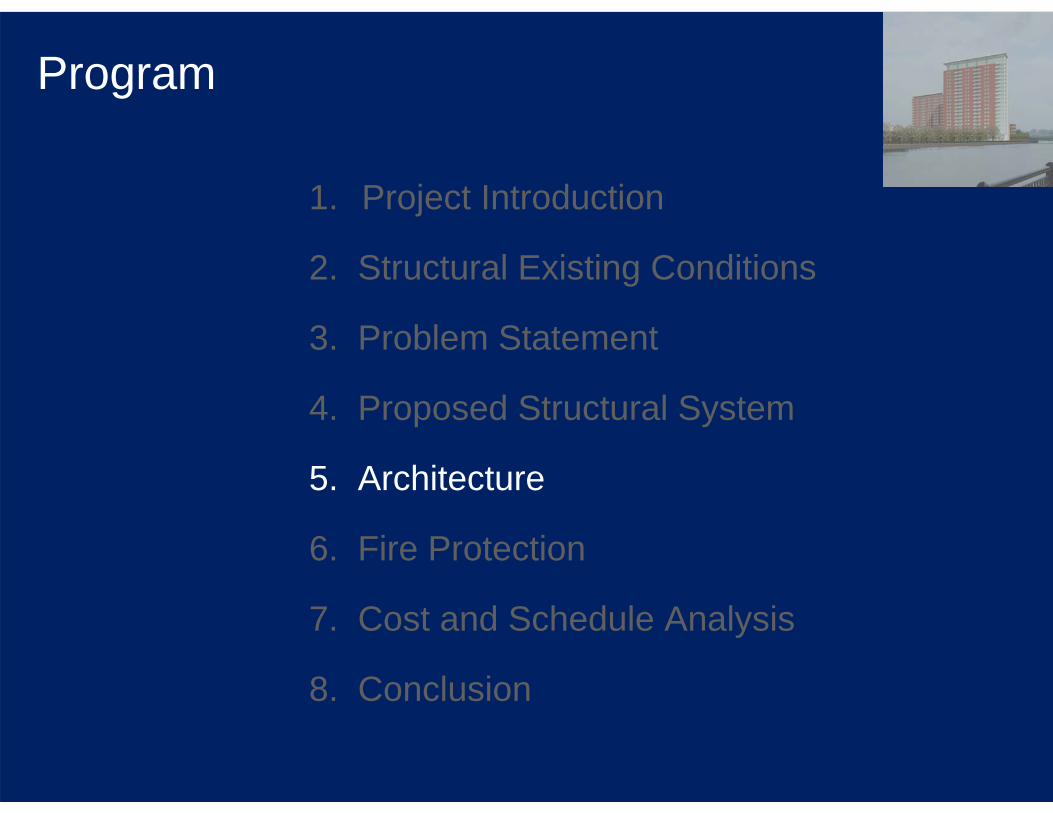
Program
1. Project Introduction
2. Structural Existing Conditions
3. Problem Statement
4. Proposed Structural System
5. Architecture
6. Fire Protection
7. Cost and Schedule Analysis
8. Conclusion

Program
1. Project Introduction
2. Structural Existing Conditions
3. Problem Statement
4. Proposed Structural System
5. Architecture
6. Fire Protection
7. Cost and Schedule Analysis
8. Conclusion

Project IntroductionGeneral Project DataProject Name: The Residences at Christina Landing
Scope: 228,884 SF Residential with Limited Commercial
Cost: $32,800,000
Owner: The Buccini / Pollin Hotel Partners III, LLC
Architect / Engineer: KLING
Contractor / CM: Gilbane Building Company

Project IntroductionScope DetailGeneral: 173 one and two bedroom apartments, fitness center, great room, and on-site parking
Building Height: 240’ to top of high parapet
Typical Floor to Floor Height: 10’
Typical Floor Square Footage: 12,012 SF
TYPICAL FLOOR PLAN

Program
1. Project Introduction
2. Structural Existing Conditions
3. Problem Statement
4. Proposed Structural System
5. Architecture
6. Fire Protection
7. Cost and Schedule Analysis
8. Conclusion
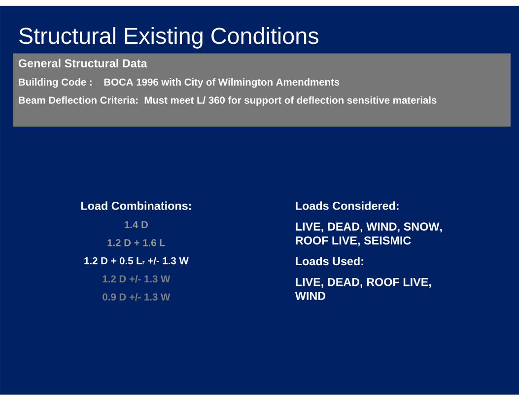
Structural Existing ConditionsGeneral Structural DataBuilding Code : BOCA 1996 with City of Wilmington Amendments
Beam Deflection Criteria: Must meet L/ 360 for support of deflection sensitive materials
Load Combinations:1.4 D
1.2 D + 1.6 L
1.2 D + 0.5 Lr +/- 1.3 W
1.2 D +/- 1.3 W
0.9 D +/- 1.3 W
Loads Considered:
LIVE, DEAD, WIND, SNOW, ROOF LIVE, SEISMIC
Loads Used:
LIVE, DEAD, ROOF LIVE, WIND

Structural Existing ConditionsSitePrevious Use: Concrete Batch Plant
Surface Materials: 2” Asphalt over 8” Concrete Slab
Subsurface Materials: Concrete Fill, Stone, and Soil Materials
Underlying Natural Soils: Silty & Clayey Sand AND Hard Silt OVER Sand
Underlying Natural Rock: Gneiss (fractured in certain areas)
Depth – 48’ to 69’ below surface

Structural Existing ConditionsFoundation System• Steel H Piles (175 ton Capacity)
• Average Depth = 70’
• Reinforced Concrete Pile Caps and Grade Beams
• Site conditions caused unforeseen difficulties
• Piles vibrated into soil not driven

Structural Existing ConditionsGravity System• Square or Circular Cast-In-Place Reinforced Concrete Columns
• 8” Two-way Reinforced Concrete Flat Slabs
• Meets deflection criteria
TYPICAL FLOOR FRAMING PLAN

Structural Existing ConditionsLateral System• 12” Cast-In-Place Reinforced Concrete Shearwall Core
• Extends Full Height of Building
• Located Centrally along West Wall

Program
2. Structural Existing Conditions
3. Problem Statement
4. Proposed Structural System
5. Architecture
6. Fire Protection
7. Cost and Schedule Analysis
8. Conclusion
1. Project Introduction

Problem StatementA comparison of both the materials cost estimate and schedule ofconstruction between the existing concrete system and the proposed steel system will determine if the steel system is feasible.
WILL THE PROPOSED STEEL SYSTEM AFFECT COST AND SCHEDULE?
WILL THE PROPOSED STEEL SYSTEM WORK WITH EXISTING ARCHITECTURAL FEATURES?

Program
2. Structural Existing Conditions
3. Problem Statement
4. Proposed Structural System
5. Architecture
6. Fire Protection
7. Cost and Schedule Analysis
8. Conclusion
1. Project Introduction

Proposed Structural System
LIVE LOAD:Public = 100 psf
Private = 40 psf
DEAD LOAD = 20 psf
ROOF LIVE LOAD = 150 psf (for mechanical equipment)
WIND LOAD = 39 psf max
General Structural DataBuilding Code : BOCA 1996 with AISC LRFD Steel Standards
Beam Deflection Criteria: Must meet L/ 360 for support of deflection sensitive materials
DESIGNED IN RAM STRUCTURAL SYSTEM
6 DIFFERENT FLOOR TYPES:1. SECOND
2. TYPICAL
3. 20TH (load transfer from penthouse floors)
4. LOWER PENTHOUSE
5. UPPER PENTHOUSE
6. UPPER ROOF

Proposed Structural SystemPossible Gravity Systems Studied• Two-way Waffle Flat Slab (CONCRETE SYSTEM - NOT CONSIDERED)
• One-way Concrete Joists (CONCRETE SYSTEM - NOT CONSIDERED)
• Non-Composite Beams with Non-Composite Deck
• Composite Beams with Composite Deck
• Steel Joists with Non-Composite Deck (DEFLECTION CRITERIA - NOT CONSIDERED)
Existing System
Non-Composite Beams with Non-Composite Deck
Composite Beams with Composite Deck
+
Typical Bay: Column Lines 6-7 and A-B

Proposed Structural SystemGravity System• Composite Steel Beams with Non-Composite Steel Deck
• All Members are W Shapes
• Deck: 3” concrete topping/ welded wire mesh, 6” total depth
• BOCA 96 Load Combinations
• AISC LRFD Method for economy of members
• May need to look at vibration control on second floor
• Meets Deflection Criteria
• Decreases overall weight of building
• May require more uplift control
← Typical Bay from
Studied Systems

Proposed Structural SystemLateral System• Not Emphasized But Considered for Cost Comparison
• Braced Frames In Place of Existing Shearwall Core
• Braced Frames Around Stairwells and Elevator Shafts
• Designed for Wind Resistance NOT Seismic
• All Members are W Shapes
• Does NOT meet Steel Code for Lateral Force Resistance
• Larger Members Required to meet Code
Typical Frame Layout Plan
Program
2. Structural Existing Conditions
3. Problem Statement
4. Proposed Structural System
5. Architecture
6. Fire Protection
7. Cost and Schedule Analysis
8. Conclusion
1. Project Introduction

ArchitectureChanges• Floorplans / Elevations
• Building Height
Floorplans
Steel Columns placed directly where Concrete Columns were in existing system.• May require more “cover-up” for aesthetics
Elevations
Overall Look stays same.• Pre-cast concrete architectural panels in Curtain Wall System
• Panels need to be adjusted to compensate for new floor to floor height
Building Height
Increases to compensate for increased plenum space.• Typical Floor to Floor height: 12’ instead of 10’
• Overall height: 275’ instead of 240’
Program
2. Structural Existing Conditions
3. Problem Statement
4. Proposed Structural System
5. Architecture
6. Fire Protection
7. Cost and Schedule Analysis
8. Conclusion
1. Project Introduction

Fire ProtectionGeneral DetailsCodes: BOCA 96 and NFPA Life Safety Code
Minimum Fire Resistance Rating: 2 hours
Proposed System• Steel Structural System – Protection required
• Spray Applied Cementitious Fireproofing Agent for all exposed surfaces – Average Thickness 1 5/8”
• Uses same Automatic Sprinkler System
• Uses same Egress Plans
Existing System:• Concrete Structural System – NO Protection required
• Automatic Sprinkler System
• Egress Plans Satisfy LSC
COST OF FIRE PROOFING
$520,309
Monokote® Fireproofing - the world's most widely specified spray applied cementitious fireproofing
RS Means: $$/ BF of steel

Program
2. Structural Existing Conditions
3. Problem Statement
4. Proposed Structural System
5. Architecture
6. Fire Protection
7. Cost and Schedule Analysis
8. Conclusion
1. Project Introduction

Cost and Schedule AnalysisExisting SystemTotal Cost of Structural System: $6,172,851 (includes Labor and Materials)
Due to unforeseen complications with the foundation system the structural system is possibly 0 - 4 weeks behind.
Start: October 12, 2003
Finish: April 4, 2005
Substantial Completion: December 1, 2005
SCHEDULE OF CONSTRUCTION

Cost and Schedule AnalysisProposed SystemTotal Cost of Structural System: $4,134,730 (includes Labor, Materials, and Fire Protection)
Cost will increase with Lateral Member Size, which will need to increase for Code Requirements.
Does NOT include complex Connections.
Lead Time: 7 months (mill - 10 weeks / fabrication - 18 weeks)
RS Means: Crane averages 45 pieces/ day
Start: October 12, 2003
Finish: August 12, 2005
Substantial Completion:
April 2006
SCHEDULE OF CONSTRUCTION(Steel NOT Ordered Prior)
Start: October 12, 2003
Finish: January 14, 2005
Substantial Completion:
September 2005
SCHEDULE OF CONSTRUCTION(Steel Ordered Prior)

Cost and Schedule Analysis
Steel Ordered Prior: - 3 months
Steel NOT Ordered Prior: +4 months
Finish: April 4, 2005
Substantial Completion:
December 2005
EXISTING SYSTEM
Finish: January 14, 2005
Substantial Completion:
September 2005
PROPOSED SYTEM
$6,172,851 $4,134,730COST:
SCHEDULE:
DIFFERENCE: - $2,038,121
Comparison of Existing and Proposed• Total Cost of Structural System
• Schedule of Construction
Increased cost of lateral system due to member sizes should not create more than 50% increase in price, based on the fact that the steel for lateral system is not more than 50% of entire steel. The steel system should still cost less than the existing.

Program
2. Structural Existing Conditions
3. Problem Statement
4. Proposed Structural System
5. Architecture
6. Fire Protection
7. Cost and Schedule Analysis
8. Conclusion
1. Project Introduction
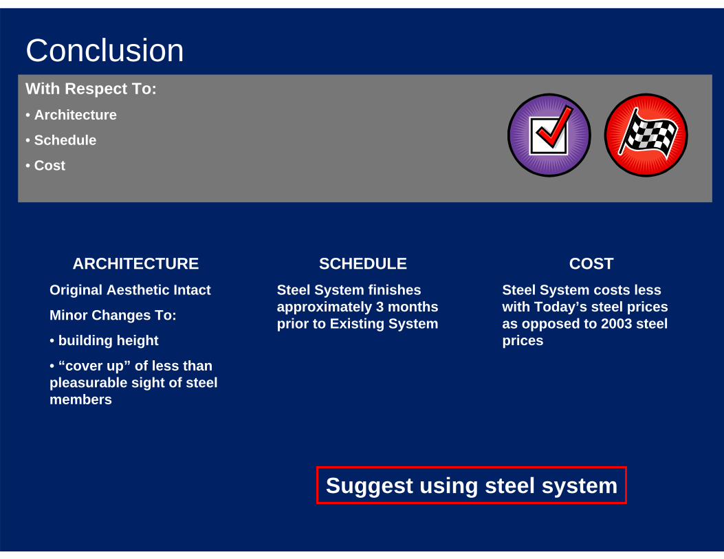
ConclusionWith Respect To:• Architecture
• Schedule
• Cost
COSTSteel System costs less with Today’s steel prices as opposed to 2003 steel prices
ARCHITECTUREOriginal Aesthetic Intact
Minor Changes To:
• building height
• “cover up” of less than pleasurable sight of steel members
SCHEDULESteel System finishes approximately 3 months prior to Existing System
Suggest using steel system

Thank You
Questions?


![Untitled-1 [abodethehomes.com]abodethehomes.com/pdf/Zen-Residences-Brochure.pdf · 2018-10-20 · ZEN RESIDENCES The Zen Residences pread over vast, lush green splendor, The Zen Residences](https://img.dokumen.tips/doc/110x75/5f3754dc86c050386263410f/untitled-1-2018-10-20-zen-residences-the-zen-residences-pread-over-vast-lush.jpg)