Embed Size (px)
Citation preview

Research Progress Concerning
the Application of HTS cable system
on Power Grid in Korea
LS Cable & System
HTS System Business Team
Cheol-hwi Ryu, Ph.D.
Oct. 11, 2011

Development of HTS Cable in Korea► R/D program in Korea
► Overview of LS CNS Status
Demonstration of 22.9kV/50MVA HTS Cable System
Developing Progress of 154kV/1GVA HTS Cable System
Future Plan

’01 ’02 ’03 ’04 ’05 ’06 ’07 ’08 ’09 ’10 ’11 ’12 ’13 ’14 ’15 ’16
Developing
22.9kV
/50MVA
30m (1-Φ)
Carrying out
Int’l Certification &
Long-term Test
22.9kV/50MVA
100m
Progressed
154kV/1GVA
100m
MOST1)
Developing
22.9kV
/50MVA
30m (3-Φ)
Demonstration
in Actual Grid
Actual Grid
(ICHEON S/S)
22.9kV/50MVA
500m
Actual Grid
(ICHEON S/S)
22.9kV/150MVA
100m
Actual Grid
(JEJU Island)
DC 80kV/500mBasic
R/D for
DC
200kV
MKE2)
Developing
DC 200kV/5GW
Demonstration
in Actual Grid
Actual Grid
(JEJU Island)
154kV/500MVA 1km
DAPAS3) Program
Commercial
Target1)MOST: Ministry Of Science & Technology2)MKE: Ministry of Knowledge & Economy3)DAPAS: Development of Advanced Power System by Applied Superconductivity Technologies
Pilot
Project
4/Page
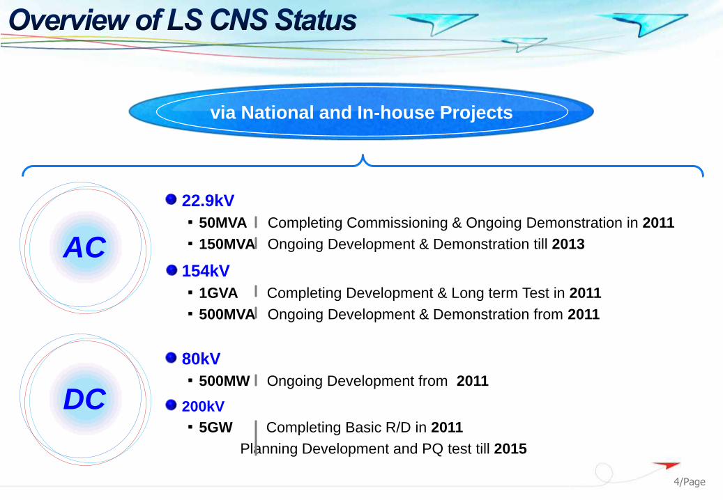
AC
22.9kV
▪ 50MVA Completing Commissioning & Ongoing Demonstration in 2011
▪ 150MVA Ongoing Development & Demonstration till 2013
154kV
▪ 1GVA Completing Development & Long term Test in 2011
▪ 500MVA Ongoing Development & Demonstration from 2011
DC
80kV
▪ 500MW Ongoing Development from 2011
200kV
▪ 5GW Completing Basic R/D in 2011
Planning Development and PQ test till 2015
via National and In-house Projects

Development of HTS Cable in Korea
Developing Progress of 154kV/1GVA HTS Cable System
Contents
Demonstration of 22.9kV/50MVA HTS Cable System► Components
► Installation
► Operation
Future Plan

6/Page
1
2
3
4
5
22.9kV/50MVA HTS Cable
Termination
Joint
Cooling System
Offset System
12345
Air view of HTS Cable System in Icheon S/S
Bending point: total 9 with 90° bending angle

7/Page
KEPCO Icheon Substation
Electrical Characteristics
- Nominal Voltage: 22.9kV
- Rated Current: 1.25kA
Physical Characteristics
- Cable Length: ~ 500m
- Cold Dielectric Design
- 3 phases in One Cryostat
- HTS wire: YBCO Coated Conductor
Hardware
- 300m and 200m HTS Cable
- Outdoor Termination (3-Φ in 1 Cryostat)
- Joint bay (3-Φ in 1 Cryostat)
Installation/Commissioning: July 2011
Grid Application: Aug. 19, 2011
Overview of HTS Cable System in Icheon S/S

8/Page
HTS Cable
SIS GISA D/L
B D/L
C D/L
D D/L
GIS22.9kV CNCO
600mm2 2cct
22.9kV CNCO
600mm2 2cct
Sequence Trip Signal Transmission
154kV/22.9kV
System Interconnection
E D/L

9/Page
Pitch Determination
for Each Layer
Impedance Matching
(2G wire)
EM field Calculation
Fabrication
HTS Shield
HTS Conductor
Optimal Design for Conductor/Shield Stranding & Fabrication
HTS Cable

Vacuum
Tcold= 77KThot= 300K
SpacerOuter layer
Inner layer
HTS Cable
Cryostat Displacement Simulation
Introduction of Seamless Aluminum Cryostat for HTS Cable
10/Page
HTS Cable

11/Page
Test Details Result
22.9kV 50MAVA HTS Cable 30m
Proto type test (2005)
- Long term test (load cycle test) Pass
- Long term test (cool down test) Pass
- DC critical current Pass
- Withstand voltage test Pass
- AC loss measurement Pass
- Summary of the test results
22.9kV 50MVA HTS Cable 100m
type test (2007)
- Load cycle (cooling circuit and Cryostat pressure
check)Pass
- Thermal cycle (shrinkage of cable) Pass
- Dielectric loss factor (Tan δ) Pass
- Dielectric security Pass
- Partial discharge Pass
- DC critical current Pass
- Visual inspection of HTS cable sample Pass
- Cable bending test Pass
HTS Cable
Type Test on previous proto-type of 22.9kV/50MVA

12/Page
Design
- Cold Dielectric
- Outer Diameter: 145mm
- Seamless Al Cryostat
- PVC Sheath
- Insulation Level up to 35kV Grade
Coverable range: 13.2kV ~ 35kV
- 3-core type Seamless Al Cryostat
- Fault Current Pass with Stabilizer
Characteristics
Specification
- 22.9kV (Nominal), 13.2kV (Phase)
- 1,260A (50MVA)
- Short Circuit Rating: 25kA/30cycle (Cu Stabilizer)
- Application of Cryogenic System (Forced Circulation Method)
HTS Cable

13/Page
Manufacturing
HTS Cable
Stranding of
Former
Former is wound up
using stranding
machine. The
diameter and the
surface of former
should be controlled
precisely to make
even and uniform
shape of HTS wires
Wrapping &
Cushion Layer
Stainless steel and
carbon paper tapes
shall be wound to
bind the former
according to the
designed diameter
Stranding of HTS &
Conductor Screen
HTS wires and LPP
papers shall be
wound over the
cushion layer, which
will be controlled
together using
stranding machine
modified for HTS
cable
Electric Insulation
& Insulation Screen
During the lapping of
LPP papers, tension
shall be carefully
controlled for
insulation quality and
bending characteristic
Inner Cryostat
The height and pitch
of corrugated Al
cryostat is critical to
bending characteristic
Vacuum
Conditioning
The vacuum region
between inner and
outer cryostat of the
cable shall be
subjected to vacuum
pumping for at least
30 days at a
temperature of 30℃
MLI Taping
After cleaning the
surface of inner
cryostat, MLI is
wrapped and 4 Teflon
spacers shall be
stranded on the
surface of MLI
Outer Cryostat
The height and pitch
of corrugated Al
cryostat is critical to
bending characteristic
Outer Jacket
During the extrusion,
cable diameter is
measured by X-ray
scan

14/Page
Joint Box
Compact Design
(500mm Ø, 3.5m L)
Insulation Level up to 35kV Grade
Coverable range: 13.2kV ~ 35kV
Pre-fabricated components
Pressure withstand: Min. 15bar
Termination
Compact Design
3-Φ in one cryostat (22.9kV)
Pressure withstand: Min. 15bar
Pre-fabricated components
Polymer composite Bushing
Pre-fabricated
•Jointing at site
Pre-fabricated
Termination & Joint

15/Page
Buffer for balancing System pressure
and fault current
Evaporating
Latent Heat Type
Overview
Cooling system
Open-loop type using Decompression unit
Capacity: 6.5kW

16/Page
Item Specification
Operating
Condition
Inlet Temp. of Cable 69K
Inlet Temp. of Cable 73K
Circulation Flow rate of LN2 0.5kg/s
Pressure 3barG ~ 7.5barG
Fault Current 25kA, 30cycles
Heat Load
Cable & Termination 4100W
Cooling System 1010W
Difference of
Pressure
Cable & Termination 1.4bar
Cooling System 1.1bar
Specification
Cooling system

17/Page
Component Function View
Decompression
Pump
Vacuum pump :
Dropping the
pressure of Sub-
cooler
Evaporator:
Increasing temp. of
GN2 flowing in the
vacuum pump
Heat
Exchanger Supercooling LN2
Circulation
Pump Circulating LN2
Sensor
Thermometer
Pressure sensor
Flow sensor
Vacuum sensor
Component Function View
Reservoir
Storage of LN2
Start point of LN2
circulation
Buffer for balancing
system pressure &
fault current
Circulation
Unit
Bulit-in circulation
pump & flowmeter
Decompression
Cryostat
Cooling LN2 by
evaporating latent
heat
Valve Box
Valves
for open and close of
decompression
cryostat
Valve
Open and close of
LN2 flow
Flow control of LN2
Components
Cooling system

Evaluating Unmanned Operation System for Cooling System
No. Item Specification
1 MS(Master Station) • Notifying Alarm and trip to the SCADA and User by E-mail and SMS.
2 CS(Control System) • Communicating with REM, DUM and Cryogenic Refrigerant by profibus
3 REM(Reservoir Module)• Controlling Reservoir Module Independently by PLC.
• controlled by CS and Communicating with CS.
• DUM and Cryogenic Refrigerant: Operated by the Temp.of the HTS Cable.4 DUM(Decompression Unit Module)
5 Cryogenic Refrigerant
6 LTS(Load Termination System)
• Explosion-proof type(IP 55)
• Controlled by CS and Communication with CS.7 JBS(Joint Box System)
8 STS(Source Termination System)
LTS JTS STS REM PLC
DUM PLC
Control Net ProfiBus
Ethernet
HMI (Server PC) HMI (Client PC)Local Network
UserDate Acquisition
Input
Control ValueMS
PLC duplex configuration
(watchdog, quick change when Failed)
Control system

Level Action countermeasure
3 Engineers standby within 24hrs Sending SMS to people in charge
2Alarming for observation to decide cutting power or not
Engineers standby within 5hrs & Clearing alarms after measures
Informing to 2nd line of SCADA
Sending SMS to people in charge
1 Stopping the operation: Cutting powerInforming to 1st line of SCADA
Sending SMS to people in charge
Action Plan According to Fault Level
Condition for Deciding Faults
Step Level Deciding Faults SetupMaintaining
Time
1
1
Breakdown Fulfilling conditions: Inner pressure of Reservoir & Load-side termination Under 2barG 10sec.
2 Fire Installing the fire alarm in Cooling room and Joint room
3 Explosion &
Damage of
HTS wire
Fulfilling conditions: Inlet temp. of cable (2 points), Joint (2 points) Over 75K 10sec.
4 Fulfilling conditions: Pressure of outlet of circulation pump & source-side termination Over 6.5bar G 0.5sec.
5
2
Breakdown Fulfilling conditions: Inner pressure of Reservoir & Load-side termination Under 2.5barG 10sec.
6 Explosion &
Damage of
HTS wire
Fulfilling conditions: Inlet & Outlet temp. of cable (4 points), Joint (2 points) Over 73K 20sec.
7Fulfilling conditions: Pressure of outlet of circulation pump & Source-side
terminationOver 6bar G 5sec.
8
Maintaining
Cooling
system
Flow rates of LN2 Under 0.2kg/s 10sec.
9 Fulfilling conditions: Vacuum condition of cable, joint & termination Over 0.1torr 10sec.
10 Fulfilling conditions: Inner pressure of pneumatic tank Under 4.2bar 10sec.
11 Fulfilling conditions: Level of LN2 tank Under 15% 10sec.
12 3Whole
systemInforming people in charge after checking malfunction or abnormality of all sensors
Control system

Item Standard Spec. Result
1 DC Voltage Test (Jacket) IEC 60840 10kV for 1min. Pass
2 Heat Loss Measurement LS Standard 3.5W/m Pass
3 DC IC Measurement KS C 6111-6 3.27kA@70K Pass
4 AC loss Measurement LS Standard 1.25W/m/Phase Pass
5 DC Voltage Test KEPCO Standard 46kV for 10min. Pass
6 Visual Inspection LS Standard Drawing Pass
Test Results
the world’s first experience to measure AC loss at rated current (1,250A)
in actual power grid
21/Page
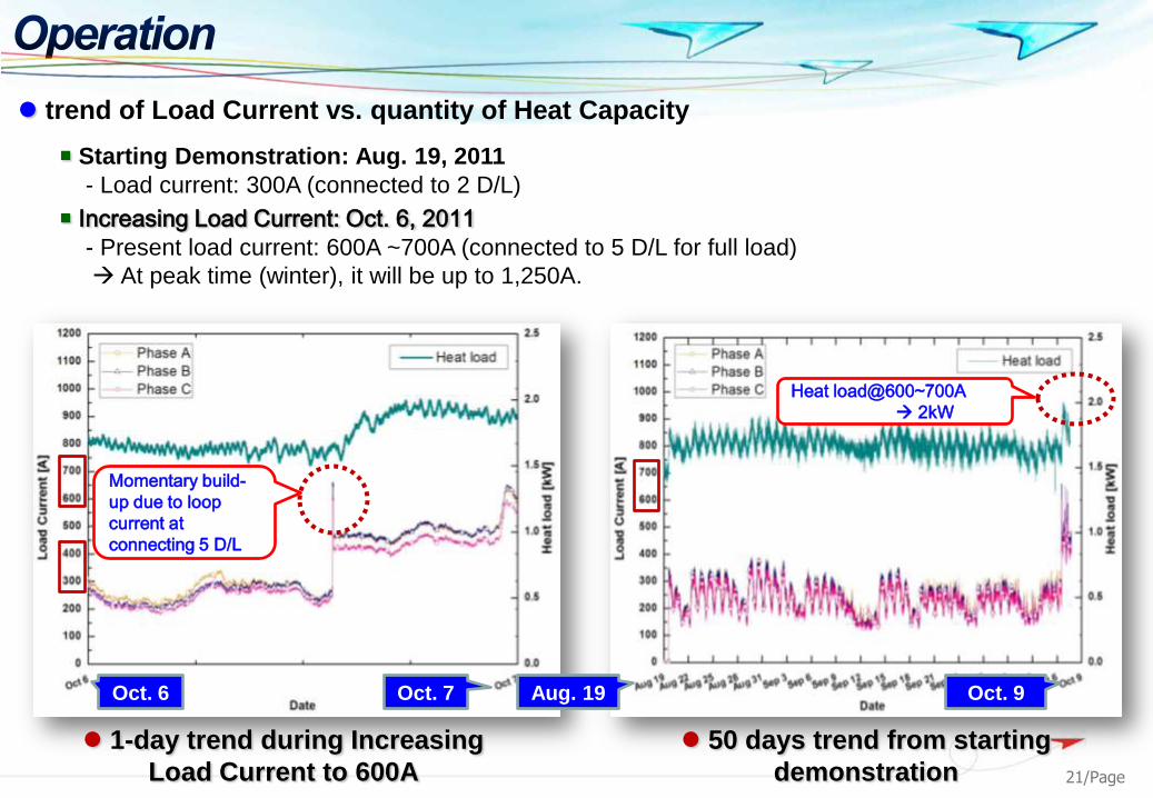
trend of Load Current vs. quantity of Heat Capacity
1-day trend during Increasing
Load Current to 600A
50 days trend from starting
demonstration
Starting Demonstration: Aug. 19, 2011
- Load current: 300A (connected to 2 D/L)
Increasing Load Current: Oct. 6, 2011
- Present load current: 600A ~700A (connected to 5 D/L for full load)
At peak time (winter), it will be up to 1,250A.
Momentary build-
up due to loop
current at
connecting 5 D/L
Heat load@600~700A
2kW
Oct. 6 Oct. 7 Aug. 19 Oct. 9

22/Page
Development of HTS Cable in Korea
Demonstration of 22.9kV/50MVA HTS Cable System
Developing Progress of 154kV/1GVA HTS Cable System
► Criteria of HTS Cable & Cryogenic System
► Cryogenic Termination
Future Plan

23/Page
Outer Cryostat
Former/Stabilizer
HTS Phase Conductor
Insulation
HTS Shield
LN2
Inner Cryostat
Thermal Insulation
(MLI + Vacuum)
Rated Voltage: 154kV, (U0=89kV, Um=170kV)
Rated Current: 3.75kArms (5.3kApeak)
BIL: 750kV
Design Fault Current: [email protected]
Electrical Characteristics
Cold Dielectric Design
Single Phase in One Aluminum Cryostat
Physical Characteristics
2 Stirling type Cryo-cooler (650W@65K)
Subcooled LN2 is circulated by a pump.
Cryogenic Cooling System

1 Cycle
Voltage
105kV : 1.2U0
16h (No Load)
8h (Load)
Vo
ltage &
Cu
rren
t
Time (h)
Load Cycle Test at 1.2Uo for 40 days was successfully finished.
.consttV n
Load cycle test: 1.3Uo x 30cycles
Vtest =105kV(1.2Uo), 40cycles
30/1)60/36530(tk = 1.189
Load Cycle Test

PD & AC Dielectric Security [email protected] for 30 min. were tested successfully
30/1)30/602436530(tk 5.1 @ 30 min
Vtest = 1.5Uo (133.5kV), 30min
AC Dielectric Security Test
• Applied Voltage: 1.5 Uo
• Testing Frequency: 18.0MHz
• PD < 5pC
[PD@Uo] [[email protected]]
PD Test
AC Dielectric Security & PD Test

DC Ic@70K 100m System with termination
Current [A]
Target DC Current@70K > 7,000A
Estimate the DC Ic of Cable system@70K: 8,985A
5760A
Average Ic/tape = 104.7A
DC Ic@77K, 2m cable
Confirm the DC Ic of Cable with terminations
DC Ic Measurement

27/Page
Development of HTS Cable in Korea
Future Plan► Development & Demonstration of Transmission Level
HTS Cable System
Demonstration of 22.9kV/50MVA HTS Cable System
Developing Progress of 154kV/1GVA HTS Cable System

28/Page
Title: Development & Demonstration of Transmission level HTS Cable System
Period: July, 2011 ~ June, 2016 (60months)
Supervision: KEPCO
Participant: LS CNS, KERI & Several Universities
Research Funds: USD70M (Government: USD22M , KEPCO: USD18M, LS CNS: USD30M)
Summary
○ Development of SFCL
○ Performance Evaluation &
Installation in Grid
○ Development of the Method
for O&M
○ Development of HTS Cable
○ Installation & Operation in Grid
○ Localization of HTS Cable &
Cryogenic System
○ Finding the way of institutional support for commercialization
○ Selecting the site for demonstration
○ Review of Standard for product & test
Supervision (KEPCO]
○ Grid Analysis & Relevant effect
○ Grid Operation System
○ Verification of HTS Cable
Participant 1 (KEPRI) Participant 2 (LS CNS) Participant (KEPRI)
Composition & Aim of Project

29/Page
Overview of Pilot Application
Hanlim
S/S
Hanlim C/S
(80kV,60MW)
154kV West Jeju- Hanlim T/L
#2 HVDC (2011)
(±250kV,400MW)
Anduk
S/S
West Jeju
MainlandNew Town
in Jeju
154kV Hanlim-Anduk T/L
GumAk C/S
(80kV,60MW)
154kV West Jeju –Anduk T/L
HTS-DC 80kV
(0.5km, 2013)
XLPE-DC 80kV
(0.5km, 2011)
HTS-AC 154kV
(1.0km, 2014)
: XLPE-DC
: HTS-DC
: HTS-AC