Embed Size (px)
Citation preview

375
17 The Programmable Temperature Vaporization Inlet
Introducing the Agilent PTV
Operating modes
System requirements
System componentsSampling heads
Columns and Traps
Heating the inletAdditional temperature ramps
Cooling the inletConfiguring the PTVShutdown behavior
Using the Split Modes
Flow pattern
Temperature considerationsCold split introductionHot split introduction
Control table parameters—split mode operationProcedure: Using split mode with
the column definedProcedure: Using split mode with
the column not defined
Pulsed modes
Control table parameters—pulsed split modeProcedure: Using pulsed split mode
with the column definedProcedure: Using pulsed split mode
with the column not defined
Using the Splitless Modes
Flow patterns
Temperature considerationsCold splitless introductionHot splitless introduction
Control table parameters—splitless operationStarting valuesProcedure: Using splitless mode
with the column definedProcedure: Using splitless mode
with the column not defined
Pulsed splitless mode operationControl table parameters—pulsed
splitless operationProcedure: Using pulsed splitless
mode with the column definedProcedure: Using pulsed splitless
mode with the column not defined

376
The Programmable Temperature Vaporization Inlet
Using the Solvent Vent Mode
Flow patterns
Temperature, pressure, and flowconsiderations
Sequence of operations
Timelines
When is Start Run?
Control table parameters—solvent ventoperationProcedure: Using solvent vent
mode with the column definedProcedure: Using solvent vent
mode with the column not defined
Large volume injectionChemStation requirementsCalculated valuesPossible adjustments
Maintaining a PTV
Inlet adaptersProcedure: Replacing inlet adapt-
ersProcedure: Installing columns
The septumless headProcedure: Removing the septum-
less head
Procedure: Cleaning the septum-less head
Procedure: Replacing the Teflon ferrule
The septum headProcedure: Removing the septum
headProcedure: Changing the septum
Glass inlet linersProcedure: Replacing linersReplacing the split vent trap filter
cartridgeProcedure: Leak testing the gas
plumbingProcedure: Leak testing the PTV inlet
Correcting leaksPotential leak points
Consumables and replaceable parts
377377
The Programmable Temperature Vaporization Inlet
Introducing the Agilent PTV
Operating modes
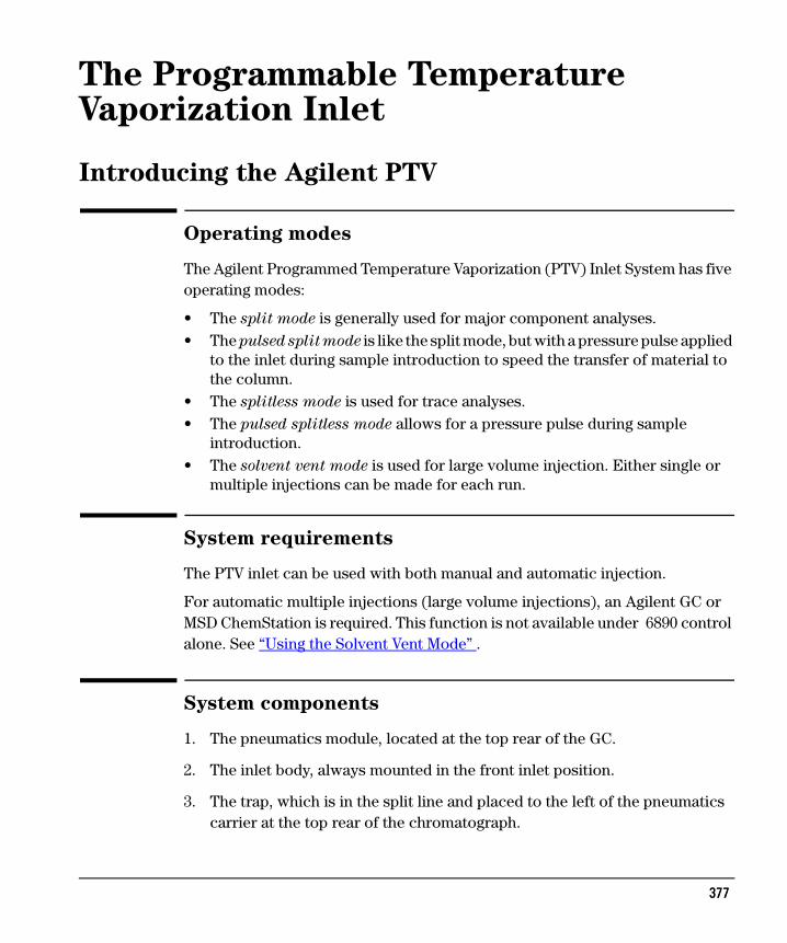
The Agilent Programmed Temperature Vaporization (PTV) Inlet System has five operating modes:
• The split mode is generally used for major component analyses.• The pulsed split mode is like the split mode, but with a pressure pulse applied
to the inlet during sample introduction to speed the transfer of material to the column.
• The splitless mode is used for trace analyses.• The pulsed splitless mode allows for a pressure pulse during sample
introduction.• The solvent vent mode is used for large volume injection. Either single or
multiple injections can be made for each run.
System requirements
The PTV inlet can be used with both manual and automatic injection.
For automatic multiple injections (large volume injections), an Agilent GC or MSD ChemStation is required. This function is not available under 6890 control alone. See “Using the Solvent Vent Mode” .
System components
1. The pneumatics module, located at the top rear of the GC.
2. The inlet body, always mounted in the front inlet position.
3. The trap, which is in the split line and placed to the left of the pneumatics carrier at the top rear of the chromatograph.

378378
Introducing the Agilent PTV The Programmable Temperature Vaporization InletSystem components
4. The coolant control valve. For liquid nitrogen, this valve is on the left outside wall of the oven. For liquid carbon dioxide, it is in the pneumatics carrier. These valves are not interchangeable—if you change coolants, you must also change all of the coolant plumbing including the valve and inlet jacket.
5. The thermocouple conversion board. It converts thermocouple readings from the inlet for use by the GC and is near the trap.
Figure 56 PTV system components
Sampling heads
Two heads are available for the PTV inlet.
• The septum head uses either a regular septum or a Merlin Microseal™ to seal the syringe passage. A stream of gas sweeps the inner side of the septum and exits through the septum purge vent on the pneumatics module. It may be used with either automatic or manual injection.
Split vent Septum purge vent
Carriersupply
Inlet
Coolantsupply
PV2 SPR
Sol PS
PV1 FS
Trap
CCV
Pneumatics modulePVSPRSolPSFSCCV
Proportional valveSeptum purge regulatorSolenoid valvePressure sensorFlow sensorCryogenic coolant valve
Alternate purge flow pathsWith septum headWith septumless head
379379
Introducing the Agilent PTV The Programmable Temperature Vaporization InletHeating the inlet
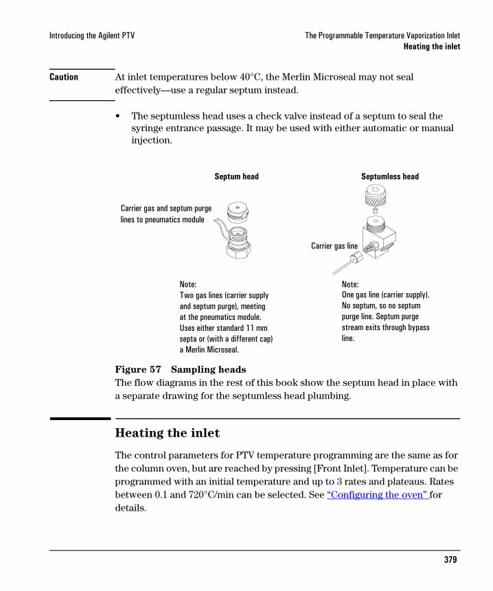
Caution At inlet temperatures below 40°C, the Merlin Microseal may not seal effectively—use a regular septum instead.
• The septumless head uses a check valve instead of a septum to seal the syringe entrance passage. It may be used with either automatic or manual injection.
Figure 57 Sampling heads
The flow diagrams in the rest of this book show the septum head in place with a separate drawing for the septumless head plumbing.
Heating the inlet
The control parameters for PTV temperature programming are the same as for the column oven, but are reached by pressing [Front Inlet]. Temperature can be programmed with an initial temperature and up to 3 rates and plateaus. Rates between 0.1 and 720°C/min can be selected. See “Configuring the oven” for details.
Septum head Septumless head
Carrier gas and septum purgelines to pneumatics module
Carrier gas line
Note:Two gas lines (carrier supplyand septum purge), meetingat the pneumatics module.Uses either standard 11 mmsepta or (with a different cap)a Merlin Microseal.
Note:One gas line (carrier supply).No septum, so no septumpurge line. Septum purgestream exits through bypass line.

380380
Introducing the Agilent PTV The Programmable Temperature Vaporization InletHeating the inlet
Caution If the initial inlet temperature and the oven initial temperature are too close, the inlet may be unable to maintain its setpoint. We recommend a difference of at least 6°C, either higher or lower.
Additional temperature ramps
For most purposes, the PTV is designed to hold the sample in the inlet liner until the entire sample—there could be several injections—has been injected. Then the PTV is heated rapidly to transfer the sample to the column. This can be accomplished with an initial hold, a single ramp, and a hold at the end to complete sample transfer.
Two additional ramps are available and have several possible uses:
• The inlet can be heated to a high temperature to thermally clean the liner for the next run.
• The inlet can be programmed downward—just set the Final temp below the previous temperature—to reduce thermal stress on the inlet.
• Downward programming can be used to prepare the inlet for the next run. This can reduce cycle time for greater sample throughput.

381381
Introducing the Agilent PTV The Programmable Temperature Vaporization InletCooling the inlet
Cooling the inlet
The sample may be injected into either a cooled or heated chamber. The initial chamber temperature can be reduced to –60°C (with CO2 cooling) or to –160°C
(with liquid N2 cooling).
Caution If the initial inlet temperature and the oven initial temperature are too close, the inlet may be unable to maintain its setpoint. We recommend a difference of at least 6°C, either higher or lower.
Configuring the PTV
To configure the PTV, press [Config] [Front Inlet]. If the inlet has not been configured previously, this screen is displayed.
The 6890 GC supports only one type of coolant at a time.
Once a coolant is selected for any cryogenic device, that same coolant must be used for all such devices, including the column oven.
Since the GC can sense which coolant is used by the oven, if oven cooling is installed that coolant becomes the one that must be used by all other cooling devices.
1. Press [Config][Front Inlet] 2. Scroll to coolant type3. Press [Mode/Type]
4. Scroll to coolant used, press [Enter]
382382
Introducing the Agilent PTV The Programmable Temperature Vaporization InletCooling the inlet
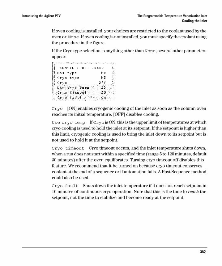
If oven cooling is installed, your choices are restricted to the coolant used by the oven or None. If oven cooling is not installed, you must specify the coolant using the procedure in the figure.
If the Cryo type selection is anything other than None, several other parameters appear.
Cryo [ON] enables cryogenic cooling of the inlet as soon as the column oven reaches its initial temperature. [OFF] disables cooling.
Use cryo temp If Cryo is ON, this is the upper limit of temperatures at which cryo cooling is used to hold the inlet at its setpoint. If the setpoint is higher than this limit, cryogenic cooling is used to bring the inlet down to its setpoint but is not used to hold it at the setpoint.
Cryo timeout Cryo timeout occurs, and the inlet temperature shuts down, when a run does not start within a specified time (range 5 to 120 minutes, default 30 minutes) after the oven equilibrates. Turning cryo timeout off disables this feature. We recommend that it be turned on because cryo timeout conserves coolant at the end of a sequence or if automation fails. A Post Sequence method could also be used.
Cryo fault Shuts down the inlet temperature if it does not reach setpoint in 16 minutes of continuous cryo operation. Note that this is the time to reach the setpoint, not the time to stabilize and become ready at the setpoint.

383383
Introducing the Agilent PTV The Programmable Temperature Vaporization InletCooling the inlet
Shutdown behavior
Both Cryo timeout and Cryo fault can cause cryo shutdown. If this happens, the inlet heater is turned off and the cryo valve closes. The GC beeps and displays this message:
The inlet heater is monitored to avoid overheating. If the heater remains on at full power for more than 2 minutes, the heater is shut down. The GC beeps and displays this message:
To recover from either condition, turn the GC off, then on, or enter a new setpoint.
384384
Using the Split Modes The Programmable Temperature Vaporization InletFlow pattern
Using the Split Modes
Flow pattern
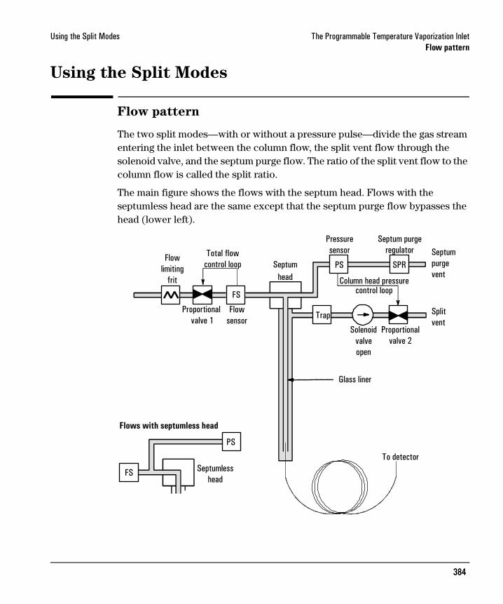
The two split modes—with or without a pressure pulse—divide the gas stream entering the inlet between the column flow, the split vent flow through the solenoid valve, and the septum purge flow. The ratio of the split vent flow to the column flow is called the split ratio.
The main figure shows the flows with the septum head. Flows with the septumless head are the same except that the septum purge flow bypasses the head (lower left).
Flowlimiting
frit
Total flowcontrol loop
Proportional valve 1
Flowsensor
Septumhead
Pressuresensor
Septum purgeregulator Septum
purgevent
Proportionalvalve 2
Solenoidvalveopen
Trap
Column head pressurecontrol loop
SPRPS
FS
Septumlesshead
PS
FS
To detector
Flows with septumless head
Glass liner
Splitvent

385385
Using the Split Modes The Programmable Temperature Vaporization InletTemperature considerations
Temperature considerations
Cold split introduction
For cold split sample introduction, use an initial inlet temperature below the normal boiling point of the solvent. If the liner volume is enough to hold all the vaporized solvent, start the first inlet temperature ramp at 0.1 minutes with a high heating rate (500°C/min or higher). The final temperature should be high enough to volatilize the heaviest analytes from the liner and should be held for at least 5 minutes. A final temperature of 350°C for 5 minutes has proven sufficient to quantitatively transfer C44.
For larger injection volumes or to eliminate the solvent, hold the initial temperature long enough to vent the solvent through the Split vent and then begin the first ramp. Use a fast rate for thermally stable analytes. Slower rates may help minimize thermal degradation in the inlet.
A single temperature ramp is enough for the injection process. The remaining ramps may be used to clean the liner or to reduce the inlet temperature in preparation for the next injection.
Hot split introduction
For hot split introduction, set an initial temperature high enough to volatilize the analytes. No additional thermal parameters are required as the inlet will maintain the setpoint throughout the run.
Because of the small liner volume (about 120 microliters), the PTV has a limited injection capacity with hot split introduction. Injection volumes exceeding 1 µL in the hot split mode may overflow the inlet causing analytical problems. Cold split introduction avoids this potential problem.

386386
Using the Split Modes The Programmable Temperature Vaporization InletControl table parameters—split mode operation
Control table parameters—split mode operation
Mode: The current operating mode—split
Temp Actual and setpoint inlet initial temperatures.
Init time Hold time at the inlet initial temperature.
Rate # Temperature program rate for inlet thermal ramps 1, 2, and 3.
Final temp # Final inlet temperature for ramps 1, 2, and 3.
Final time # Hold time at Final temp 1, 2, and 3.
Pressure Actual and setpoint inlet pressure.
Split ratio The ratio of split flow to column flow. Column flow is set at the Column 1 or Column 2 control table. This line does not appear if your column is not defined.
Split flow Flow, in mL/min, from the split/purge vent. This line does not appear if your column is not defined.
Total flow These are the actual and setpoint values of the total flow into the inlet, which is the sum of the split flow, column flow, and septum purge flow. When you change the total flow, the split ratio and split flow change while the column flow and pressure remain the same.
Procedure: Using split mode with the column defined1. Verify that the column, carrier gas, and flow or pressure program (if used)
are configured correctly. See “Flow and Pressure Control” .
2. Press [Front Inlet].
a. Scroll to Mode: and press [Mode/Type]. Select Split.
b. Set the inlet temperature and any desired ramps.
c. If you want a specific split ratio, scroll to Split ratio and enter that number. The split flow will be calculated and set for you.
d. If you want a specific split flow, scroll to Split flow and enter that number. The split ratio will be calculated and displayed for you.
Split ratio = Split flow Column flow

387387
Using the Split Modes The Programmable Temperature Vaporization InletControl table parameters—split mode operation
e. If desired, turn on Gas saver. Set the Saver time after the injection time.
3. Press [Prep Run] before manually injecting the sample if the Gas Saver is on (see page 285).
Procedure: Using split mode with the column not defined1. Verify that the column, carrier gas, and flow or pressure program (if used)
are configured correctly. See “Flow and Pressure Control” .
2. Press [Front Inlet].
a. Set temperature.
b. Set total flow into the inlet. Measure flows out of the split vent and septum purge vent using a flow meter.
c. Subtract the septum purge flow from Total flow to get split flow.
Press [Mode/Type]
Only one rate is necessaryfor this example.Additional rates are at the user’s discretion.
If using gas saver,set time after injection time.

388388
Using the Split Modes The Programmable Temperature Vaporization InletControl table parameters—split mode operation
d. Calculate the split ratio. Adjust as needed.
Press [Mode/Type]
Only one rate is necessaryfor this example.Additional rates are at the user’s discretion.
Septum purge
Split vent
Front of instrument

389389
Using the Split Modes The Programmable Temperature Vaporization InletPulsed modes
Pulsed modes
The pressure pulse modes (split and splitless) increase inlet pressure just before the beginning of a run and return it to the normal value after a specified amount of time. The pressure pulse sweeps the sample out of the inlet and into the column faster, reducing the chance for sample decomposition in the inlet. If your chromatography is degraded by the pressure pulse, a retention gap may help restore peak shape.
You must press the [Prep Run] key before doing manual injections in the pressure pulse mode.
You can do column pressure and flow programming when in the pressure pulse mode. However, the pressure pulse will take precedence over the column pressure or flow ramp.
Figure 58 Pressure pulse and column flow or pressure
0 1 2 3 4 5 6 7 8
Actualpressure
Pressure pulse
Pressure (or flow) program
Time (min)

390390
Using the Split Modes The Programmable Temperature Vaporization InletControl table parameters—pulsed split mode
Control table parameters—pulsed split mode
Mode: The current operating mode—pulsed split.
Temp Actual and setpoint inlet temperatures.
Init time Hold time at the initial inlet temperature.
Rate # Temperature program rate for inlet thermal ramps 1, 2, and 3.
Final temp # Final inlet temperature for ramps 1, 2, and 3.
Final time # Hold time at Final temp 1, 2, and 3.
Pressure Actual and setpoint inlet pressure before and after the pressure pulse. This is the starting point of a pressure program or the fixed pressure if a program is not used.
Pulsed pres The inlet pressure you desire at the beginning of a run. The pressure rises to this setpoint after [Prep Run] is pressed and remains constant until Pulse time elapses, when it returns to Pressure.
Pulse time Inlet pressure returns to its normal setpoint at this time after Start Run.
Split ratio The ratio of split flow to column flow. Column flow is set at the Column 1 or Column 2 control table. This line does not appear if your column is not defined.
Split flow Flow, in mL/min from the split/purge vent. This line does not appear if your column is not defined.
Total flow The total flow into the inlet, the sum of the split flow, column flow, and septum purge flow. When you change total flow, the split ratio and split flow change while column flow and pressure remain the same. When a pressure pulse is used, total flow increases to keep the split ratio constant.

391391
Using the Split Modes The Programmable Temperature Vaporization InletControl table parameters—pulsed split mode
Procedure: Using pulsed split mode with the column defined1. Verify that the column, carrier gas, and flow or pressure program (if used)
are configured correctly. See “Flow and Pressure Control” .
2. Press [Front Inlet].
a. Scroll to Mode: and press [Mode/Type]. Select Pulsed Split.
b. Set the inlet temperature and any desired ramps.
c. Enter values for Pulsed Pres and Pulse time.
d. If you want a specific split ratio, scroll to Split ratio and enter that number. The split flow is calculated and set for you.
e. If you want a specific split flow, scroll to Split flow and enter that number. The split ratio is calculated and displayed for you.
f. Turn Gas saver on, if desired. Set the time greater than Pulse time.
3. Press [Prep Run] (see page 285) before injecting a sample manually.
Split ratio = Split flow Column flow
Press [Mode/Type]
392392
Using the Split Modes The Programmable Temperature Vaporization InletControl table parameters—pulsed split mode
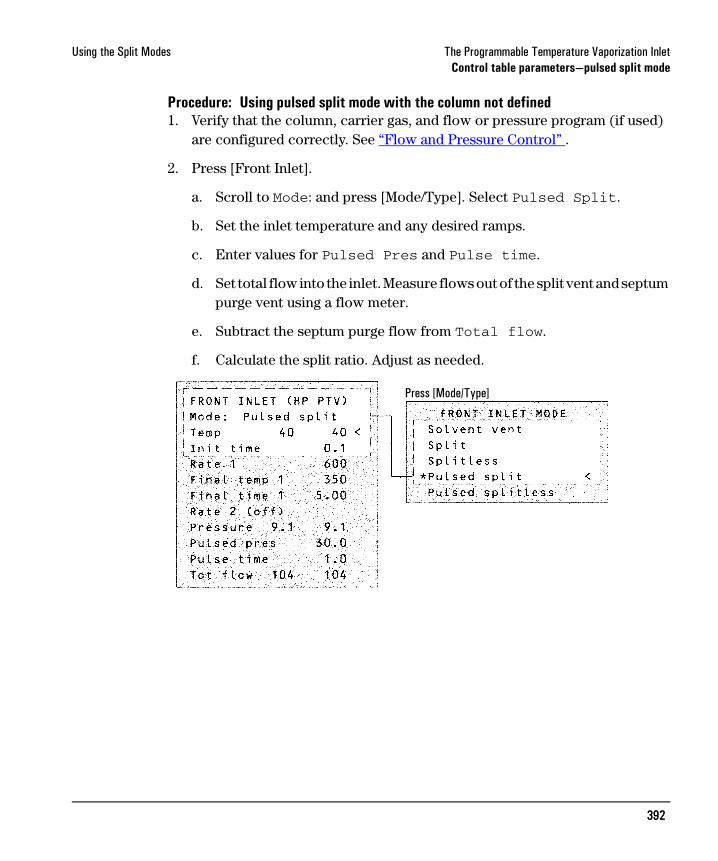
Procedure: Using pulsed split mode with the column not defined1. Verify that the column, carrier gas, and flow or pressure program (if used)
are configured correctly. See “Flow and Pressure Control” .
2. Press [Front Inlet].
a. Scroll to Mode: and press [Mode/Type]. Select Pulsed Split.
b. Set the inlet temperature and any desired ramps.
c. Enter values for Pulsed Pres and Pulse time.
d. Set total flow into the inlet. Measure flows out of the split vent and septum purge vent using a flow meter.
e. Subtract the septum purge flow from Total flow.
f. Calculate the split ratio. Adjust as needed.
Press [Mode/Type]
393393
Using the Splitless Modes The Programmable Temperature Vaporization InletFlow patterns
Using the Splitless Modes
Flow patterns
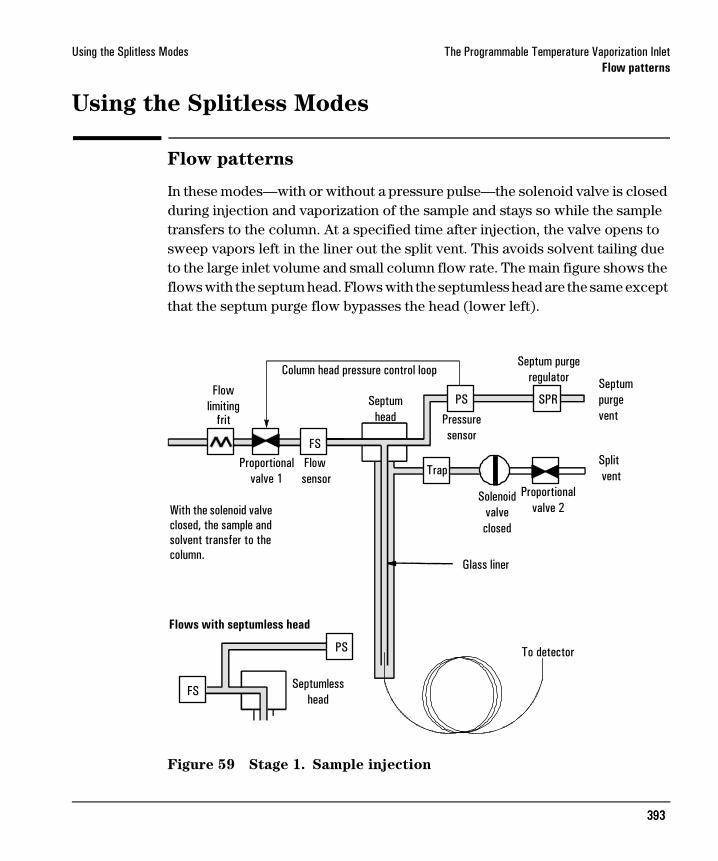
In these modes—with or without a pressure pulse—the solenoid valve is closed during injection and vaporization of the sample and stays so while the sample transfers to the column. At a specified time after injection, the valve opens to sweep vapors left in the liner out the split vent. This avoids solvent tailing due to the large inlet volume and small column flow rate. The main figure shows the flows with the septum head. Flows with the septumless head are the same except that the septum purge flow bypasses the head (lower left).
Figure 59 Stage 1. Sample injection
Flowlimiting
frit
Proportionalvalve 1
Flow sensor
Pressuresensor
Septum purgeregulator Septum
purgevent
Trap
Solenoidvalveclosed
Proportionalvalve 2
Split vent
Glass liner
To detector
PS SPRSeptumhead
FS
PS
Septumlesshead
FS
Column head pressure control loop
Flows with septumless head
With the solenoid valve closed, the sample and solvent transfer to the column.

394394
Using the Splitless Modes The Programmable Temperature Vaporization InletFlow patterns
Figure 60 Stage 2. Purging
FS
PS SPR
Trap
PS
FSSeptumless
head
To detector
Flowlimiting
frit
Proportionalvalve 1
Flow sensor
Septumhead
Pressuresensor
Septum purgeregulator Septum
purge vent
Splitvent
Proportionalvalve 2
Solenoidvalveopen
Glass liner
After the sample hastransferred to the column,the solenoid valve opens topurge remaining solventvapor from the system.
Flows with septumless head
Total flowcontrol loop
Column head pressurecontrol loop

395395
Using the Splitless Modes The Programmable Temperature Vaporization InletFlow patterns
Figure 61 Flows, pressures, and temperatures
Split vent flow
Purgeflow
Saverflow
Inlet pressure
Inlettemperature
Finaltemp 1
Inittemp
Column flow program
SPLITLESS OPERATION
Inlet ispressure controlled
PrepRun
StartRun
PurgeTime
SaverTime
StopRun
PostTime
PrepRun
StartRun
PurgeTime
StopRun
PostTime
PrepRun
StartRun
PurgeTime
Post Pres
Inlet Pres
396396
Using the Splitless Modes The Programmable Temperature Vaporization InletTemperature considerations
Temperature considerations
Cold splitless introduction
For cold splitless introduction, use an initial inlet temperature below the normal boiling point of the solvent. For most solvents, starting the first inlet temperature ramp at 0.1 minutes provides good transfer and reproducibility. A program rate of 500°C/min or higher is appropriate for thermally stable analytes. A final temperature of 350°C, held for 5 minutes, has quantitatively transferred up to C44 alkane.
A main advantage of temperature programmability is that the inlet can be heated gently to transfer delicate analytes. If the oven temperature is initially low enough to refocus the analytes on the column, the inlet heating rate can be made slower (e.g., 120°C/min). This reduces thermal degradation from the inlet and can improve peak shape and quantitation.
For most applications of cold splitless, a single temperature ramp is enough. The remaining ramps can be used to clean the liner or to decrease the inlet temperature to prepare for the next injection.
Hot splitless introduction
For hot splitless introduction, select an initial temperature high enough to volatilize the analytes. No additional temperature parameters are required as the inlet will maintain the setpoint throughout the run.
Because of the small liner volume (about 120 µL), the PTV cannot contain vapor resulting from large liquid injection volumes. Injection volumes greater than 1 µL may overflow vapor from the inlet, causing analysis variations. Cold splitless introduction avoids this problem.

397397
Using the Splitless Modes The Programmable Temperature Vaporization InletControl table parameters—splitless operation
Control table parameters—splitless operation
Mode: The current operating mode—splitless.
Temp Actual and setpoint inlet temperatures.
Init time Hold time at the initial inlet temperature.
Rate # Temperature program rate for inlet thermal ramps 1, 2, and 3.
Final temp # Final inlet temperature for ramps 1, 2, and 3.
Final time # Hold time at Final temp 1, 2, and 3.
Pressure Actual and setpoint inlet pressure in psi, bar, or kPa
Purge time The time, after the beginning of the run, when you want the purge valve to open.
Purge flow The flow, in mL/min, from the purge vent, at Purge time. You will not be able to specify this value if operating with your column not defined.
Total flow The Total flow line displays the actual flow to the inlet during a Pre-run (Pre-run light is on and not blinking) and during a run before purge time. You cannot enter a setpoint at these times. At all other times, Total flow will have both setpoint and actual values.
Starting values
A successful splitless injection consists of these steps:
1. Inject the sample and temperature program the inlet to vaporize it.
2. Use a low column flow and low oven temperature to create a solvent-saturated zone at the head of the column.
3. Use this zone to trap and reconcentrate the sample at the head of the column.
4. Wait until all, or at least most, of the sample has transferred to the column. Then discard the remaining vapor in the inlet—which is mostly solvent—by opening a purge valve. This eliminates the long solvent tail that this vapor would otherwise cause.
5. Raise the oven temperature to analyze the sample.
398398
Using the Splitless Modes The Programmable Temperature Vaporization InletControl table parameters—splitless operation
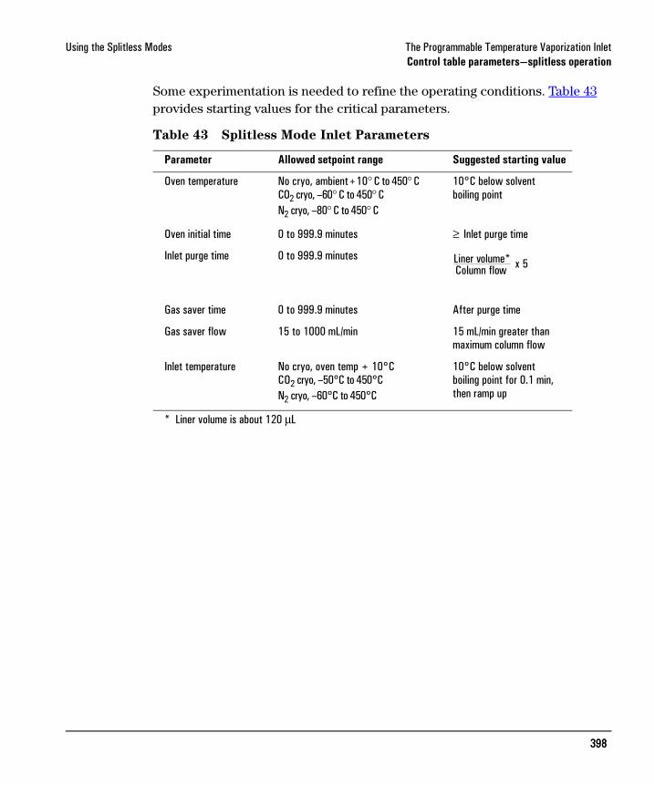
Some experimentation is needed to refine the operating conditions. Table 43 provides starting values for the critical parameters.
Table 43 Splitless Mode Inlet Parameters
Parameter Allowed setpoint range Suggested starting value
Oven temperature No cryo, ambient+10° C to 450° CCO2 cryo, –60° C to 450° CN2 cryo, –80° C to 450° C
10°C below solventboiling point
Oven initial time 0 to 999.9 minutes ≥ Inlet purge time
Inlet purge time 0 to 999.9 minutes
Gas saver time 0 to 999.9 minutes After purge time
Gas saver flow 15 to 1000 mL/min 15 mL/min greater than maximum column flow
Inlet temperature No cryo, oven temp + 10°CCO2 cryo, –50°C to 450°CN2 cryo, –60°C to 450°C
10°C below solventboiling point for 0.1 min,then ramp up
* Liner volume is about 120 µL
Liner volume*Column flow x 5
399399
Using the Splitless Modes The Programmable Temperature Vaporization InletControl table parameters—splitless operation
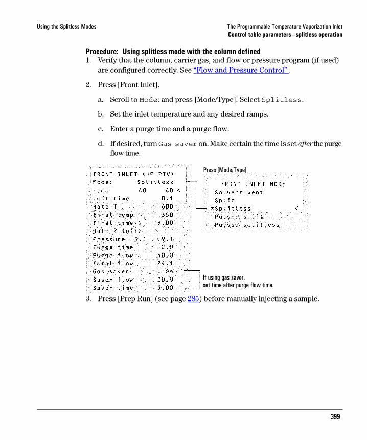
Procedure: Using splitless mode with the column defined1. Verify that the column, carrier gas, and flow or pressure program (if used)
are configured correctly. See “Flow and Pressure Control” .
2. Press [Front Inlet].
a. Scroll to Mode: and press [Mode/Type]. Select Splitless.
b. Set the inlet temperature and any desired ramps.
c. Enter a purge time and a purge flow.
d. If desired, turn Gas saver on. Make certain the time is set after the purge flow time.
3. Press [Prep Run] (see page 285) before manually injecting a sample.
Press [Mode/Type]
If using gas saver,set time after purge flow time.

400400
Using the Splitless Modes The Programmable Temperature Vaporization InletControl table parameters—splitless operation
Procedure: Using splitless mode with the column not defined1. Verify that the column, carrier gas, and flow or pressure program (if used)
are configured correctly. See “Flow and Pressure Control” .
2. Press [Front Inlet].
a. Scroll to Mode: and press [Mode/Type]. Select Splitless.
b. Set the inlet temperature and any desired ramps.
c. Enter a purge time.
d. Set your total flow greater than the column flow plus the septum purge flow (about 3 to 6 mL/min) to guarantee adequate column flow.
3. Press [Prep Run] (see page 285) before manually injecting a sample.
Press [Mode/Type]

401401
Using the Splitless Modes The Programmable Temperature Vaporization InletPulsed splitless mode operation
Pulsed splitless mode operation
See page 389 for a discussion of the pulsed pressure modes.
Control table parameters—pulsed splitless operation
Mode: The current operating mode—pulsed splitless.
Temp Actual and setpoint inlet temperatures.
Init time Hold time at the initial inlet temperature.
Rate # Temperature program rate for inlet thermal ramps 1, 2, and 3.
Final temp # Final inlet temperature for ramps 1, 2, and 3.
Final time # Hold time at Final temp 1, 2, and 3.
Pressure Actual and setpoint inlet pressure before and after the pressure pulse. It sets the starting point of a pressure program or the fixed pressure if a program is not used.
Pulsed pres The inlet pressure you desire at the beginning of a run. The pressure rises to this setpoint after [Prep Run] is pressed and remains constant until Pulse time elapses, when it returns to Pressure.
Pulse time Pressure returns to its normal setpoint at this time.
Purge time The time, after the beginning of the run, that you wish the purge valve to open. Set purge time 0.1 to 0.5 minutes before pulse time.
Purge flow The flow, in mL/min, from the purge vent, at Purge time. The column must be defined.
Total flow This is the total flow into the inlet, representing a total of the column flow and the septum purge flow.

402402
Using the Splitless Modes The Programmable Temperature Vaporization InletPulsed splitless mode operation
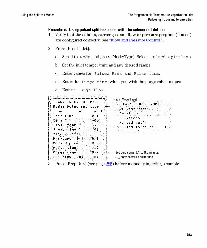
Procedure: Using pulsed splitless mode with the column defined1. Verify that the column, carrier gas, and flow or pressure program (if used)
are configured correctly. See “Flow and Pressure Control” .
2. Press [Front Inlet].
a. Scroll to Mode: and press [Mode/Type]. Select Pulsed Splitless.
b. Set the inlet temperature and any desired ramps.
c. Enter values for Pulsed pres and Pulse time.
d. Enter the Purge time when you wish the purge valve to open.
e. Enter a Purge flow.
f. Turn Gas saver on, if desired. Set the time after the purge flow time.
3. Press [Prep Run] (see page 285) before manually injecting a sample.
Press [Mode/Type]
Set purge time 0.1 to 0.5 minutesbefore pressure pulse time.
If using gas saver,set time after purge flow time.
403403
Using the Splitless Modes The Programmable Temperature Vaporization InletPulsed splitless mode operation
Procedure: Using pulsed splitless mode with the column not defined1. Verify that the column, carrier gas, and flow or pressure program (if used)
are configured correctly. See “Flow and Pressure Control” .
2. Press [Front Inlet].
a. Scroll to Mode: and press [Mode/Type]. Select Pulsed Splitless.
b. Set the inlet temperature and any desired ramps.
c. Enter values for Pulsed Pres and Pulse time.
d. Enter the Purge time when you wish the purge valve to open.
e. Enter a Purge flow.
3. Press [Prep Run] (see page 285) before manually injecting a sample.
Press [Mode/Type]
Set purge time 0.1 to 0.5 minutesbefore pressure pulse time.

404404
Using the Solvent Vent Mode The Programmable Temperature Vaporization InletFlow patterns
Using the Solvent Vent Mode
Flow patterns
The sample is injected into a cold inlet. If conditions are properly chosen and the sample is suitable, analytes deposit in the inlet liner while the solvent evaporates and is swept out. Large or multiple injections can be used to concentrate sample in the inlet before transferring to the column for analysis.
The main figure shows the flows with the septum head. Flows with the septumless head are the same except that the septum purge flow bypasses the head (lower left).
Stage 1. Sample and vent
FS
PS SPR
Trap
PS
FS Septumless head
To detector
Flowlimiting
frit
Proportionalvalve 1
Flow sensor
Septumhead
Pressuresensor
Septum purgeregulator Septum
purge vent
Split
Proportionalvalve 2
Solenoidvalveopen
Glass liner
vent
Column head pressurecontrol loop
Flows with septumless head
During sampling and ventingsolenoid valve is open. Inlet isat Init temp, at or belowsolvent boiling point. Solvent vapors are swept out the vent,while sample deposits on the liner walls or packing.
Total flow control loop
405405
Using the Solvent Vent Mode The Programmable Temperature Vaporization InletFlow patterns
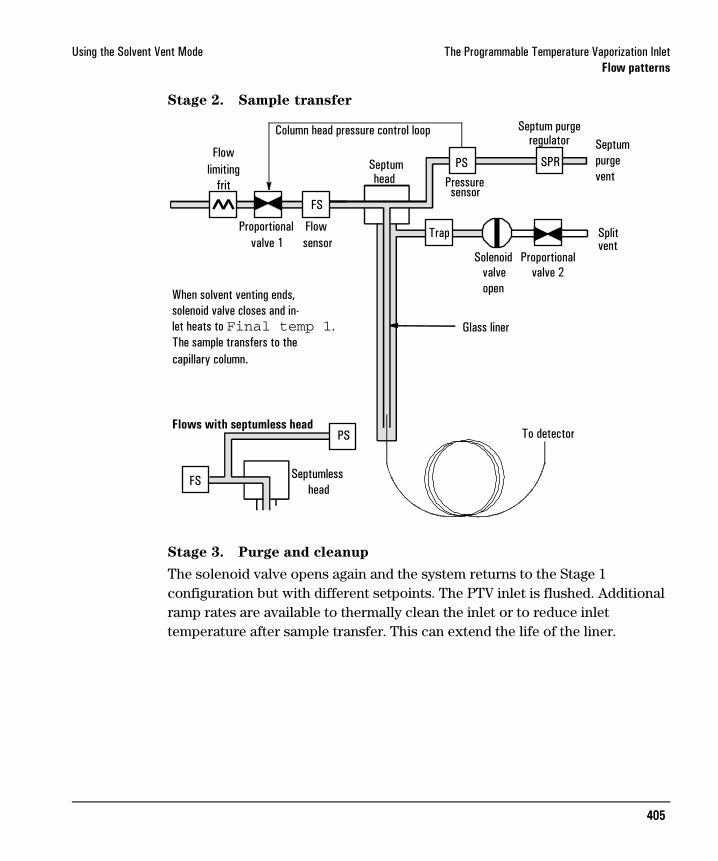
Stage 2. Sample transfer
Stage 3. Purge and cleanup
The solenoid valve opens again and the system returns to the Stage 1 configuration but with different setpoints. The PTV inlet is flushed. Additional ramp rates are available to thermally clean the inlet or to reduce inlet temperature after sample transfer. This can extend the life of the liner.
FS
PS SPR
Trap
PS
FS Septumless head
To detector
Flowlimiting
frit
Proportionalvalve 1
Flow sensor
Septumhead
regulator Septumpurge vent
Split
Proportionalvalve 2
Solenoidvalveopen
Glass liner
vent
Flows with septumless head
sensorPressure
Septum purge
When solvent venting ends,solenoid valve closes and in-let heats to Final temp 1. The sample transfers to the
Column head pressure control loop
capillary column.
406406
Using the Solvent Vent Mode The Programmable Temperature Vaporization InletTemperature, pressure, and flow considerations
Temperature, pressure, and flow considerations
The solvent vent mode goes through three distinct pneumatic states; venting, sample transfer, and purging. The vent portion allows the inlet pressure and the vent flow to be adjusted to optimize solvent elimination. The transfer state mimics traditional splitless operation and transports the analytes from the liner to the column. The purging mode allows the user to prepare the inlet for the next run.
A fundamental difficulty with solvent vent mode is the potential loss of volatile analytes with the solvent. Several solutions are possible for this situation:
• The inlet liner can be packed with a more retentive material, such as Tenax. This greatly improves volatile analyte recovery but may impact recovery of higher boiling materials.
• Some of the solvent can be left in the liner when sample transfer begins. The residual solvent acts like a stationary phase and retains volatile material, but at the expense of a larger solvent peak.
• The inlet temperature can be reduced. This reduces the vapor pressure of the volatile analytes and permits higher recoveries.
Solvent removal can be speeded up by:
• Reducing pressure in the inlet during sample introduction—the Ventpressure parameter
• Increasing flow through the inlet—the Vent flow parameterWhile all these possibilities do complicate use of the PTV, they provide increased flexibility and new potential to solve difficult problems.

407407
Using the Solvent Vent Mode The Programmable Temperature Vaporization InletSequence of operations
Sequence of operations
These are the steps in a typical analysis using the solvent vent mode.
Some important points
• The flow through the column is governed by the pressure in the inlet. This is controlled, during the analysis part of the process, by the flow or pressure setpoint or program entered for the column.
• The controlling times must be in the order shown; Vent end time before Purge time before Saver time.
• Vent end time must occur before the inlet starts to heat and release analytes.
• Purge time must occur before the oven begins to heat and move sample through the column.
Step Parameter Value
1 Before injection Flow at split vent Either Purge flow or Saver flow
Inlet pressure Derived from column setpoint
The system is resting, with Purge flow (or Saver flow, if on) through the inlet.
2 Prep Run begins Flow at split vent Vent flow setpoint
Inlet pressure Vent pressure setpoint
Setpoints change to prepare for injection. When GC is ready, the sample is injected. Inlet and oven temperature program Init times begin. Solvent venting and analyte trapping begin.
3 At Vent end time Flow at split vent None, solenoid valve closed
Inlet pressure Column pressure setpoint
Solvent venting ends, analyte transfer begins as inlet heats up.
4 At Purge time Flow at split vent Purge flow setpoint
Inlet pressure Column pressure setpoint
Analyte transfer ends, inlet is purged of residual vapor. Analysis begins.
5 At Saver time Flow at split vent Saver flow setpoint
Inlet pressure Column pressure setpoint
Analysis ends, carrier flow reduced to save gas (if Saver is on).

408408
Using the Solvent Vent Mode The Programmable Temperature Vaporization InletTimelines
Timelines
Time increases downward; all other quantities increase to the right.
Figure 62 Time relationships
i5-23
Oven temp Inlet temp Inlet pressure Split vent flow
Between runs
Prep Run
Start Run
Vent end time
Purge time
Saver time
Init time
Rate 1
Final temp 1Final time 1
Other rates,temps, andtimes, ifdesired.
Init time
Rate 1
Final temp 1Final time 1
Other rates,temps, andtimes, ifdesired.
(Controlled bycolumn flow orpressure setpointor program)
(Controlled bycolumn flow orpressure setpointor program)
Ventpressure
Vent flow
Saver or Purgeflow
(Inlet ispressurecontrolled)
Purgeflow
Saverflow(if on)
Time

409409
Using the Solvent Vent Mode The Programmable Temperature Vaporization InletWhen is Start Run?
When is Start Run?
Both the inlet and oven temperature programs begin at Start Run. All times—such as Purge time—are measured from Start Run. When does Start Run occur?
• If the sample is injected manually, Start Run occurs when the user presses the Start Run key.
• If a single injection per run is made using an autosampler, Start Run occurs when the syringe carrier moves down to make the injection.
• If multiple injections per run are made using an autosampler, Start Run occurs when the syringe carrier moves down to make the first injection of the set. There are no Start Run signals for the rest of the injections in the set.These additional injections take time. The inlet and oven temperature programs, mainly the Init time values, must be adjusted to allow for this. So must the various time values that control the inlet operation. This is discussed in more detail under “Large volume injection” .
Control table parameters—solvent vent operation
Mode: The current operating mode—solvent vent.
Temp Actual and setpoint initial inlet temperatures.
Init time The time, measured from Start Run, when the initial inlet temperature hold ends. Usually greater than Vent end time.
Rate # Temperature program rate for inlet thermal ramps 1, 2, and 3.
Final temp # Final inlet temperature for ramps 1, 2, and 3.
Final time # Hold time at Final temp 1, 2, and 3. This time is a duration; it is not measured from Start Run.
Pressure Actual and setpoint inlet pressure before and after the vent period. It sets the starting point of column head pressure.
Vent pressure The inlet pressure during the vent period. By decreasing the inlet pressure while venting, solvent elimination proceeds faster. Also, the pressure reduction decreases the amount of carrier gas—and solvent vapor—that enters the column during this time.

410410
Using the Solvent Vent Mode The Programmable Temperature Vaporization InletControl table parameters—solvent vent operation
Users select from 0 to 100 psig. If 0 is chosen, the inlet uses the lowest pressure possible at the given vent flow. Table 44 shows approximate values for this minimum at various vent flows of helium. Pressures less than those in the table are not possible unless the flow is reduced.
Table 44 Minimum attainable pressures
Vent flow The flow of carrier gas out the split vent during the vent period. Higher flows sweep the liner more quickly and reduce the time for solvent elimination. For most columns, 100 mL/min vent flow eliminates solvent at an acceptable rate but puts minimal material on the column.
Vent end time The time, measured from Start Run, when solvent venting ends. For large volume injections, this time is normally greater than the time for the injection to complete.
Purge time The time, measured from Start Run, when sample transfer ends. It began at Vent end time.
Purge flow The flow of carrier gas to the inlet beginning at Purge time.
Total flow The Total flow displays the actual flow to the inlet.
Vent flow (mL/min)
Actual vent pressure at “0“ psig setpoint
Actual vent pressure at “0” kPa setpoint
50 0.7 5
100 1.3 10
200 2.6 18
500 6.4 44
1000 12.7 88

411411
Using the Solvent Vent Mode The Programmable Temperature Vaporization InletControl table parameters—solvent vent operation
Procedure: Using solvent vent mode with the column defined1. Verify that the column, carrier gas, and flow or pressure program (if used)
are configured correctly. See “Flow and Pressure Control” .
2. Press [Front Inlet].
a. Scroll to Mode: and press [Mode/Type]. Select Solvent vent.
b. Enter a vent pressure, a vent flow, and a vent end time.
c. Set the inlet temperature and ramps, as desired.
d. Enter a purge time and a purge flow.
e. If desired, turn Gas saver on. Make certain the time is set after the purge time.
3. Press [Prep Run] (see page 285) before manually injecting a sample.
Press [Mode/Type]
Should be less than Init time.Must be greater than vent end time.
Must be greater than purge time.

412412
Using the Solvent Vent Mode The Programmable Temperature Vaporization InletControl table parameters—solvent vent operation
Procedure: Using solvent vent mode with the column not defined1. Verify that the column, carrier gas, and flow or pressure program (if used)
are configured correctly. See “Flow and Pressure Control” .
2. Press [Front Inlet].
a. Scroll to Mode: and press [Mode/Type]. Select Solvent vent.
b. Enter a vent end time and a vent pressure.
c. Set the inlet temperature and ramps, as desired.
d. Enter a purge time. It must be greater than the vent end time.
e. Set total flow greater than the column flow plus the septum purge flow (about 6 mL/min) to guarantee adequate column flow.
3. Press [Prep Run] (see page 285) before manually injecting a sample.
Press [Mode/Type]
Should be less than Init time.Must be greater than vent end time.
413413
Using the Solvent Vent Mode The Programmable Temperature Vaporization InletLarge volume injection
Large volume injection
Most vaporizing inlets are designed for liquid injections in the 1 to 5 µL range. With larger injections, the vapor cloud created when the sample vaporizes may overflow the inlet and degrade the chromatography. For the PTV, the nominal liner liquid capacities are:
Table 45 Liner capacities
In the solvent vent mode, analytes are thermally trapped in the liner while the solvent is removed. With the solvent gone, the liner volume can be used for another injection. Injection can be repeated several times to concentrate the analytes from a large sample volume. After injection and solvent removal, the analytes are transferred to the column. This can replace the need for offline concentrating and minimize loss of sample.
Multiple injections by an automatic sampler can be used with the PTV to achieve large volume injection. A ChemStation controls the process.
ChemStation requirements
A GC or MSD ChemStation is necessary for multiple injection because the needed parameters are not available through the 6890 GC keyboard.
• GC ChemStation Software revision A.04.02 or lateror Software revision A.04.01 plus the software
provided with the PTV.
• MSD ChemStation Software revision A.03.00 or later
Liner Nominal liquid capacity Inertness
Open baffle 5 µL High
Glass wool packed 25 µL Lower, because of greater surface area

414414
Using the Solvent Vent Mode The Programmable Temperature Vaporization InletLarge volume injection
Table 46 Control parameters—Injector configuration subscreen
• Syringe size Full volume of the syringe.• Nanoliter Adapter Controlled by a checkbox. If checked, indicates
that a nanoliter adapter is present on the injector. If not checked, means that a nanoliter adapter is not present on the injector. The adapter is always present on the G2613A injector
• Multiple Injections Controlled by a checkbox. If checked, the sampler makes multiple injections into the inlet for each run according to the other parameters. It issues a Start Run command at the first injection only.If not checked, the sampler makes one injection—and issues a Start Run command—for each run. This is the default mode of operation.
Table 47 Control parameters—Injector screen
• Inject µL times X is the amount to be injected; Y is the number of injections to make. If the nanoliter adapter is checked on the Injector Configuration screen, the range becomes 0.02 to 0.4 x syringe volume.
• Delay A pause time, in seconds, between injections. This is added to the minimum hardware cycle time.
• Preinjection washes Number of times to wash the syringe with solvent and/or sample before the first injection. No washes are performed before the rest of the injections in a multiple injection set.
Parameter Range Default
Syringe size 0.1 to 100 µL 10 µL
Nanoliter adapter Present or not present Not present
Multiple injections Single or multiple Single
Parameter Range Default
Inject X µL Y times X: 0.1 to 0.5 × syringe volumeY: 1 to 100
X: 0.1 × syringe volumeY: 1
Delay between injections 0 to 100 seconds 0
Preinjection washes 0 to 15 0
Postinjection washes 0 to 15 0
Pumps 0 to 15 0

415415
Using the Solvent Vent Mode The Programmable Temperature Vaporization InletLarge volume injection
• Postinjection washes Number of times to wash the syringe with solvent after the last injection. No washes are performed after the rest of the injections in a multiple injection set.
• Preinjection pumps Number of times to pump the syringe plunger before drawing up the measured sample. Pump are performed only before the first injection of a multiple injection set.
Calculated values
The software calculates and displays:
• On the Injector screen: Total Product of X (Volume per injection) and Y (Injections per run).
• On the Inlets screen: Estimated total injection time The approximate total time, in minutes, to make a set of multiple injections based on the parameters entered and the mechanical cycle time of the sampler. Includes Delay between injections, pre- and post-injection dwell times, and viscosity delays.
An example
These values were used for a sample with a broad range of boiling points.
General parameters
Name Value
Sample C10 to C44 hydrocarbons in hexane
Mode Solvent vent
PTV liner Glass wool packed
Injection volume One 10.0 µL injection (25 µL syringe)
Injection speed Fast
Column 30 m x 320 µm x 0.25 µm -5, p/n 19091J-413
Column flow 4 mL/min constant flow

416416
Using the Solvent Vent Mode The Programmable Temperature Vaporization InletLarge volume injection
Inlet parameters
Name Value Name Value
Init temp 40°C Rate 2 (off)
Init time 0.3 min Pressure 15.6 psig
Rate 1 720°C/min Vent pressure 0.0 psig
Final temp 1 450°C Vent flow 100 mL/min
Final time 1 5 min Vent end time 0.2 min
Rate 2 100°C/min Purge time 2.0 min
Final temp 2 250°C Purge flow 50 mL/min
Final time 2 0 min
Oven parameters
Name Value
Init temp 40°C
Init time 2.5 min
Rate 1 25°C/min
Final temp 1 320°C
Final time 1 10.0 min
Rate 2 (off)
Detector parameters
Name Value
Detector FID
Detector temp 400°C
Hydrogen flow 40 mL/min
Air flow 450 mL/min
Makeup (N2) 45 mL/min

417417
Using the Solvent Vent Mode The Programmable Temperature Vaporization InletLarge volume injection
Figure 63 Chromatogram from one 10 µL injection
These results were compared with a splitless analysis of the same sample, which should produce 100% recovery of all analytes. The data showed that, under these conditions, compounds above C20 were completely recovered and that the recovery
was independent of injection size; Compounds lower than C20 were partially vented
with the solvent.
i5-26
C20
418418
Using the Solvent Vent Mode The Programmable Temperature Vaporization InletLarge volume injection
Possible adjustments
Depending on what you are trying to accomplish, you have a number of possible adjustments available.
To eliminate more solvent
• Increase the vent end time, inlet initial time, and purge time. This will not affect analytes that are quantitatively trapped but will eliminate more of the solvent peak.
• Increase the vent flow to sweep the liner more rapidly with the same inlet timing. Increasing vent flow raises vent pressure if it is set to 0. This puts more solvent onto the column.
• Raise the inlet initial temperature to vaporize more solvent and allow more to be eliminated. This also increases the loss of volatile analytes since their vapor pressures also increase.
To improve recovery of low boiling analytes
• Reduce inlet temperature to lower the vapor pressure of the analytes and trap them more effectively. This also reduces solvent vapor pressure and more time will be needed to eliminate it.
• Use a retentive packing in the liner. Materials such as Tenax permit higher recovery of volatile analytes but may not release higher boiling compounds. This must be considered if quantitation on these high boiling peaks is desired.
• Leave more solvent in the liner. The solvent acts as a pseudo stationary phase and helps retain volatile analytes. This must be balanced against the detector’s tolerance for solvent.
An example—continued
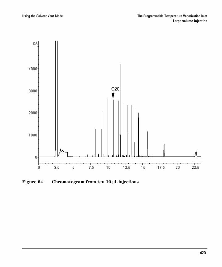
The single injection example shown on the last few pages makes it clear that a 10 µL injection does not overload the glass wool packed liner. This means that multiple 10 µL injections are possible.
It was decided to make 10 injections per run, each of 10 µL size. This would increase analytical sensitivity substantially. No adjustments were made to

419419
Using the Solvent Vent Mode The Programmable Temperature Vaporization InletLarge volume injection
improve recovery of the low boilers since the purpose of this analysis was to detect and measure the high boiling components.
The ChemStation estimated that 10 injections would require a total of 1.3 minutes. The following timing changes were made:
The result is shown in Figure 27.
Parameter Increased from To
Inlet Init time 0.3 minutes 1.6 minutes
Vent end time 0.2 minutes 1.5 minutes
Purge time 2.0 minutes 3.0 minutes
Oven Init time 2.5 minutes 3.0 minutes
420420
Using the Solvent Vent Mode The Programmable Temperature Vaporization InletLarge volume injection
Figure 64 Chromatogram from ten 10 µL injections
i5-27C20
421421
Maintaining a PTV The Programmable Temperature Vaporization InletInlet adapters
Maintaining a PTV
Inlet adapters
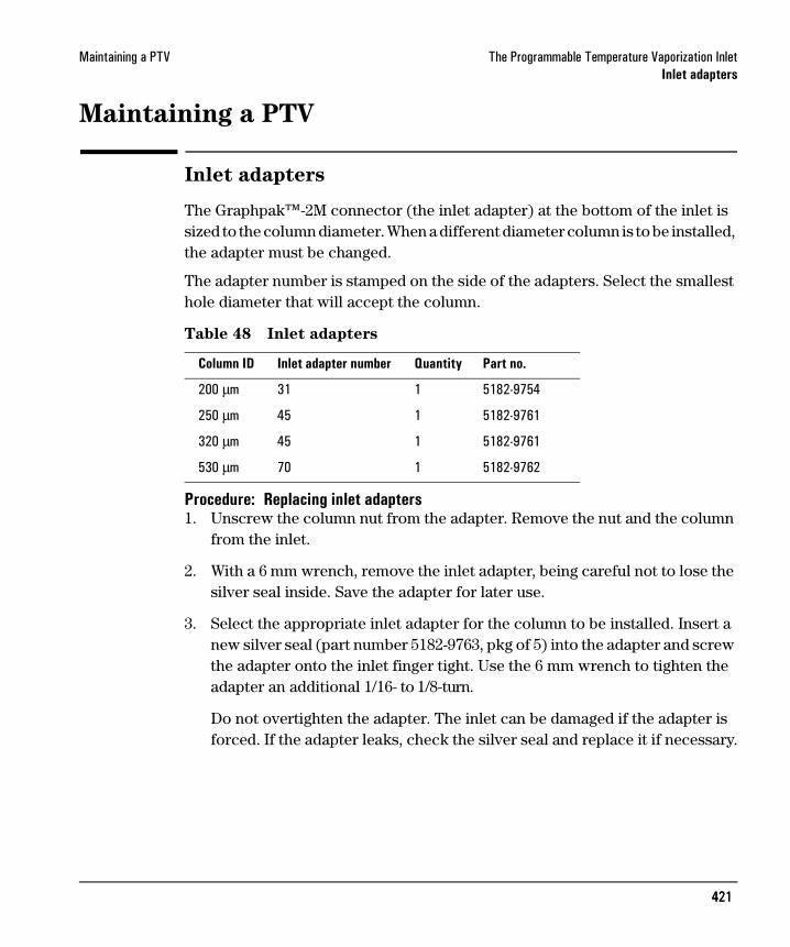
The Graphpak™-2M connector (the inlet adapter) at the bottom of the inlet is sized to the column diameter. When a different diameter column is to be installed, the adapter must be changed.
The adapter number is stamped on the side of the adapters. Select the smallest hole diameter that will accept the column.
Table 48 Inlet adapters
Procedure: Replacing inlet adapters1. Unscrew the column nut from the adapter. Remove the nut and the column
from the inlet.
2. With a 6 mm wrench, remove the inlet adapter, being careful not to lose the silver seal inside. Save the adapter for later use.
3. Select the appropriate inlet adapter for the column to be installed. Insert a new silver seal (part number 5182-9763, pkg of 5) into the adapter and screw the adapter onto the inlet finger tight. Use the 6 mm wrench to tighten the adapter an additional 1/16- to 1/8-turn.
Do not overtighten the adapter. The inlet can be damaged if the adapter is forced. If the adapter leaks, check the silver seal and replace it if necessary.
Column ID Inlet adapter number Quantity Part no.
200 µm 31 1 5182-9754
250 µm 45 1 5182-9761
320 µm 45 1 5182-9761
530 µm 70 1 5182-9762

422422
Maintaining a PTV The Programmable Temperature Vaporization InletInlet adapters
Procedure: Installing columns
Graphpak-2M ferrules are sized to the column outer diameter.
Table 49 Columns and ferrules
1. Place the appropriate Graphpak ferrule onto the column inlet end and pull it at least 30 mm from the end.
2. With a glass knife or other fused silica cutter, remove approximately 10 mm from the column end to eliminate graphite contamination.
3. Position the ferrule so that it is 17 mm from the column end. Place a small mark (typewriter correction fluid is useful) at the back of the ferrule and, making sure that the column is correctly positioned, insert the column end into the adapter.
Column ID Graphpak ferrule hole ID Quantity Part no.
200 µm 0.31 mm 10 5182-9756
250 µm 0.40 mm 10 5182-9768
320 µm 0.45 mm 10 5182-9769
530 µm 0.70 mm 10 5182-9770
2
0
22
cm 17 mm
Mark column here
423423
Maintaining a PTV The Programmable Temperature Vaporization InletThe septumless head
4. Screw the column nut on finger tight. Using a 5 mm wrench, tighten the column nut 1/8- to 1/4-turn. Be careful not to overtighten.
5. Check the connections for leaks. If there are any leaks at the column adapter, tighten it slightly more with the open end wrench provided.
The septumless head
This sampling head uses a check valve instead of a septum to seal the syringe entrance passage. It may be used with either automatic or manual injection. Syringes must have 23 gauge needles (see “Consumables and replaceable parts” ).
Procedure: Removing the septumless head1. Cool the inlet to room temperature.
2. Disconnect the carrier gas line.
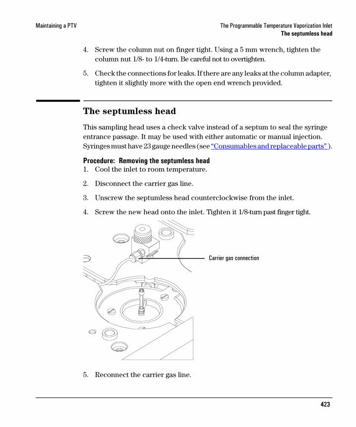
3. Unscrew the septumless head counterclockwise from the inlet.
4. Screw the new head onto the inlet. Tighten it 1/8-turn past finger tight.
5. Reconnect the carrier gas line.
Carrier gas connection
424424
Maintaining a PTV The Programmable Temperature Vaporization InletThe septumless head
6. Check all connections on the sampling head for leaks. If necessary, tighten them again by hand.
Procedure: Cleaning the septumless headMinor deposits from sample mixtures can collect in the head. Dust and abraded material particles can enter together with the syringe needle, eventually causing leaks. We recommend periodic cleaning.
1. Cool the inlet to room temperature.
2. Disconnect the carrier gas line and unscrew the head from the inlet.
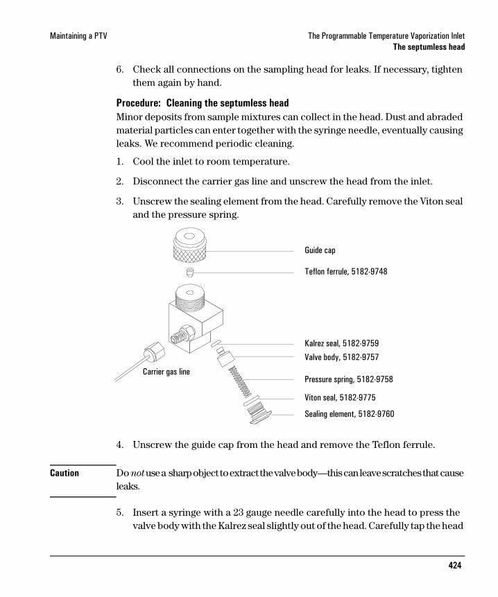
3. Unscrew the sealing element from the head. Carefully remove the Viton seal and the pressure spring.
4. Unscrew the guide cap from the head and remove the Teflon ferrule.
Caution Do not use a sharp object to extract the valve body—this can leave scratches that cause leaks.
5. Insert a syringe with a 23 gauge needle carefully into the head to press the valve body with the Kalrez seal slightly out of the head. Carefully tap the head
Guide cap
Teflon ferrule, 5182-9748
Kalrez seal, 5182-9759
Valve body, 5182-9757
Pressure spring, 5182-9758
Viton seal, 5182-9775
Sealing element, 5182-9760
Carrier gas line

425425
Maintaining a PTV The Programmable Temperature Vaporization InletThe septumless head
on a soft smooth surface so that the valve body falls outcompletely or slips so far out that you can grasp it with your fingers.
6. Remove the seal from the valve body.
7. Carefully clean all components in hexane.
8. Assemble the head in reverse order. Make sure that you work absolutely lint-free and that the seals and the pressure spring are not damaged.
9. Use this opportunity to check the Teflon ferrule. If it must be replaced, see page 426 for instructions.
10. Check the entire system again for leaks; if necessary, carefully retighten the guide cap slightly more with the syringe needle inserted and/or replace the Kalrez seal.
If the head leaks when a syringe is inserted, the Teflon ferrule is the problem. If the head leaks without a syringe inserted, the seals may need to be replaced.
426426
Maintaining a PTV The Programmable Temperature Vaporization InletThe septumless head
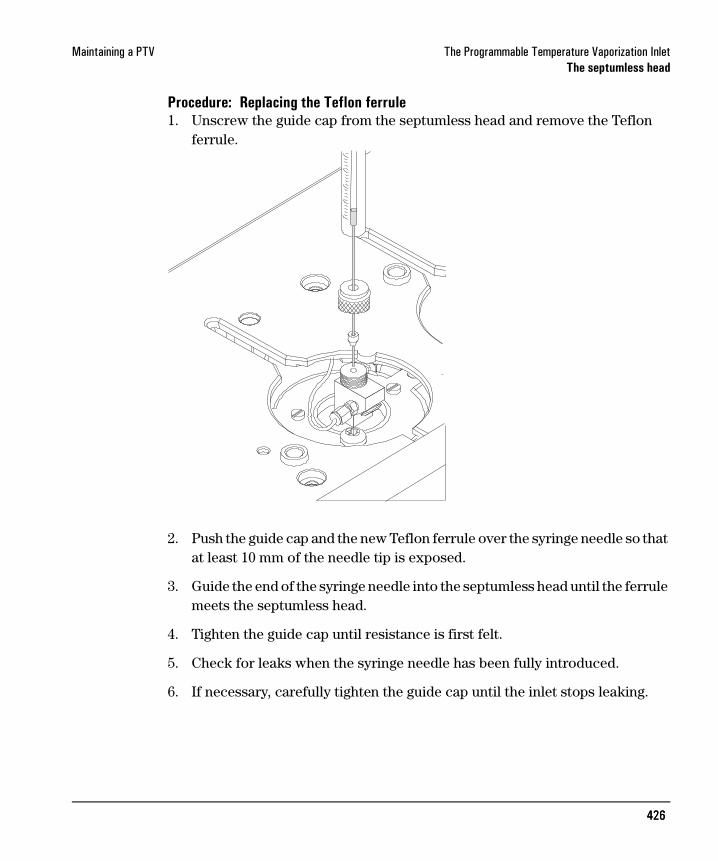
Procedure: Replacing the Teflon ferrule1. Unscrew the guide cap from the septumless head and remove the Teflon
ferrule.
2. Push the guide cap and the new Teflon ferrule over the syringe needle so that at least 10 mm of the needle tip is exposed.
3. Guide the end of the syringe needle into the septumless head until the ferrule meets the septumless head.
4. Tighten the guide cap until resistance is first felt.
5. Check for leaks when the syringe needle has been fully introduced.
6. If necessary, carefully tighten the guide cap until the inlet stops leaking.

427427
Maintaining a PTV The Programmable Temperature Vaporization InletThe septum head
The septum head
The septum head uses either a regular septum or a Merlin Microseal to seal the syringe passage. A stream of gas sweeps the inner side of the septum and exits through the septum purge vent on the pneumatics module.
Procedure: Removing the septum headThe septum head connects to the inlet via a free-spinning retaining nut.
1. Cool the inlet to room temperature.
2. Use a 5/8-inch wrench to loosen the retaining nut on the septum head.
3. Gently remove the septum head assembly from the inlet. Be careful not to overly bend the 1/16-inch lines. For best results, lift the head to clear the inlet and then push it to either side to allow access.
Retaining nut

428428
Maintaining a PTV The Programmable Temperature Vaporization InletThe septum head
4. To reinstall the septum head, gently align the head with the inlet and manually engage the free-spinning nut to the inlet.
The nut should easily turn on to the inlet. If resistance is felt, unscrew the nut and retry. Excessive force can irreparably damage the inlet.
5. Tighten the retaining nut ½-turn past finger tight.
6. Check all connections for leaks. If necessary, the retaining nut can be tightened an additional ¼-turn to eliminate leaks.

429429
Maintaining a PTV The Programmable Temperature Vaporization InletThe septum head
Procedure: Changing the septumEither a regular septum or a Merlin Microseal can be used with the septum head.
If the inlet temperature is set below 40°C, the Merlin Microseal may not seal effectively. For inlet temperatures below 40°C, use a regular septum for the inlet seal.
1. To replace the septum, cool the inlet to ambient temperature.
2. Using the inlet tool or manually, unscrew the septum cap or Merlin cap counterclockwise. If the septum head begins to turn, support it manually while removing the cap.
3. Remove the septum or Merlin Microseal, taking care not to scratch the interior of the septum head.
4. Install a new septum or Merlin Microseal and the correct cap. When installing a Merlin Microseal, note that the side where the metal parts are visible goes down.
5. Check for leaks out of the cap and tighten the cap if necessary.
MerlinMicrosealand cap
Standardseptumand cap

430430
Maintaining a PTV The Programmable Temperature Vaporization InletGlass inlet liners
Glass inlet liners
The liner is the chamber for sample deposition. Three kinds are available:
Table 50. Inlet liners
TypeInjection capacity Inertness Quantity Part no.
Open baffled liner Lowest capacity Most inert 10 5182-9751
Liner packed with silanized glass wool
Higher capacity Less inert 10 5182-9752
Unpacked liner, to be packed by the user
Depends on the packing 10 5182-9753
TypeInjection capacity Glass type
Glass wool packing*
Typical application Part no.
Single baffle liner 180 µL Borosilicate deactivated
Yes Large volume injection, not for extremely active compounds
5183-2038
Single baffle liner 200 µL Borosilicate deactivated
No General purpose 5183-2036
Multi baffle liner 150 µL Borosilicate deactivated
No Active compounds, drugs, pesticides
5183-2037
Fritted glass liner 150 µL Borosilicate deactivated
No Large volume injection, all but the most active compounds
5183-2041
*Silanized glass wool 10 gm (pesticide grade) part no. 5181-3317
431431
Maintaining a PTV The Programmable Temperature Vaporization InletGlass inlet liners
Procedure: Replacing liners1. Remove the head from the inlet. See “Procedure: Removing the septumless
head” or “Procedure: Removing the septum head” .
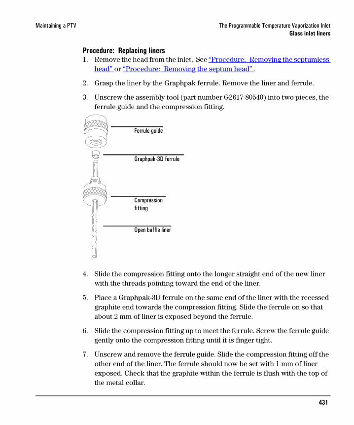
2. Grasp the liner by the Graphpak ferrule. Remove the liner and ferrule.
3. Unscrew the assembly tool (part number G2617-80540) into two pieces, the ferrule guide and the compression fitting.
4. Slide the compression fitting onto the longer straight end of the new liner with the threads pointing toward the end of the liner.
5. Place a Graphpak-3D ferrule on the same end of the liner with the recessed graphite end towards the compression fitting. Slide the ferrule on so that about 2 mm of liner is exposed beyond the ferrule.
6. Slide the compression fitting up to meet the ferrule. Screw the ferrule guide gently onto the compression fitting until it is finger tight.
7. Unscrew and remove the ferrule guide. Slide the compression fitting off the other end of the liner. The ferrule should now be set with 1 mm of liner exposed. Check that the graphite within the ferrule is flush with the top of the metal collar.
Ferrule guide
Graphpak-3D ferrule
Compression fitting
Open baffle liner
432432
Maintaining a PTV The Programmable Temperature Vaporization InletGlass inlet liners
8. Insert the glass liner into the inlet from above until the unpacked side of the ferrule rests on the top of the inlet.
9. Replace the sampling head and reconnect the lines, if necessary.
10. Check all connections for leaks. If necessary, tighten them again by hand.

433433
Maintaining a PTV The Programmable Temperature Vaporization InletGlass inlet liners
Replacing the split vent trap filter cartridge
WARNING Turn off the oven and turn off the heater for the inlet that uses the split vent trap and let them cool down. Turn off the carrier gas supply pressure.
The split vent trap may contain residual amounts of any samples or other chemicals you have run through the GC. Follow appropriate safety procedures for handling these types of substances while replacing the trap filter cartridge.
1. Turn off the inlet and the oven and allow to cool.
2. Set all GC flows to zero.
3. Remove the pneumatics cover.
4. Lift the filter trap assembly form the mounting bracket and unscrew the filter trap assembly.
5. Remove the old filter cartridge and O-rings and replace them.
6. Reassemble the trap.
7. Check for leaks.
Split vent back weldment
Replacement filter kit
Split vent frontweldment
Filter cartridge
O-rings (2)
Flow
434434
Maintaining a PTV The Programmable Temperature Vaporization InletGlass inlet liners
Procedure: Leak testing the gas plumbing
Leaks in the gas plumbing can affect chromatographic results dramatically. The following procedure checks the flow system up to but not including the inlet flow manifold. If this portion of the system proves to be leak-free, refer to the next procedure to check the inlet and inlet manifold.
Liquid leak detectors are not recommended, especially in areas where cleanliness is very important.
If you do use leak detection fluid, immediately rinse the fluid off to remove the soapy film.
WARNING To avoid a potential shock hazard when using liquid detection fluid, turn the GC off and disconnect the main power cord. Be careful not to spill leak solution on electrical leads, especially the detector heater leads.
Materials needed:
• Electronic leak detector capable of detecting your gas type or liquid leak detection fluid. If you use leak detection fluid, remove excess fluid when you have completed the test.
• Two 7/16-inch wrenches
1. Using the leak detector, check each connection you have made, for leaks.
2. Correct leaks by tightening the connections. Retest the connections; continue tightening until all connections are leak-free.

435435
Maintaining a PTV The Programmable Temperature Vaporization InletGlass inlet liners
Procedure: Leak testing the PTV inlet
There are numerous places in the inlet that can leak. This procedure lets you determine, in general, if there is an unacceptable leak in the inlet. If the inlet is leaking, you should use an electronic leak detector to pinpoint the component that is leaking.
WARNING Be careful! The oven and/or inlet may be hot enough to cause burns.
Materials needed:
• No-hole ferrule• 7/16-inch wrench• Gloves (if the inlet is hot)• Septum nut wrench (part no. 19251-00100)• 9/16-inch wrench• 1/8-inch SWAGELOK cap• Bubble flow meter
1. Complete the following preliminary steps:
• If you have entered parameters that you do not want to lose, store them as a method.
• Turn the oven off.
• Cool the oven and inlet to room temperature.
• Turn the inlet pressure off.
• Remove the column, if one is installed, and plug the column fitting with the column nut and a no-hole ferrule.
• Remove the old septum and replace it with a new one. For instructions, see “Procedure: Changing the septum” .
2. Remove the column from the inlet fitting on the inside of the oven.
3. If a septum head is installed, and the quality of the septum (or Microseal) and Graphpak-3D ferrule on the glass liner are unknown, replace them now.
436436
Maintaining a PTV The Programmable Temperature Vaporization InletGlass inlet liners
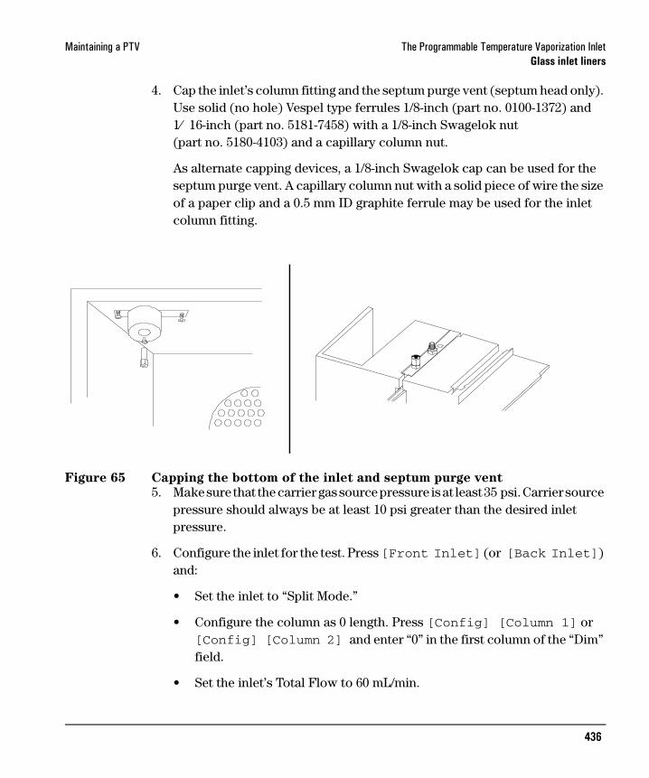
4. Cap the inlet’s column fitting and the septum purge vent (septum head only). Use solid (no hole) Vespel type ferrules 1/8-inch (part no. 0100-1372) and 1⁄ 16-inch (part no. 5181-7458) with a 1/8-inch Swagelok nut (part no. 5180-4103) and a capillary column nut.
As alternate capping devices, a 1/8-inch Swagelok cap can be used for the septum purge vent. A capillary column nut with a solid piece of wire the size of a paper clip and a 0.5 mm ID graphite ferrule may be used for the inlet column fitting.
Figure 65 Capping the bottom of the inlet and septum purge vent
5. Make sure that the carrier gas source pressure is at least 35 psi. Carrier source pressure should always be at least 10 psi greater than the desired inlet pressure.
6. Configure the inlet for the test. Press [Front Inlet] (or [Back Inlet]) and:
• Set the inlet to “Split Mode.”
• Configure the column as 0 length. Press [Config] [Column 1] or [Config] [Column 2] and enter “0” in the first column of the “Dim” field.
• Set the inlet’s Total Flow to 60 mL/min.

437437
Maintaining a PTV The Programmable Temperature Vaporization InletGlass inlet liners
• Set the pressure to 25 psi.
• Set the inlet temperature to its normal operating temperature.
7. Wait approximately 15 seconds for equilibration.
If pressure cannot be achieved, either a very large leak is present in the system, or the supply pressure is not high enough.
8. Turn the inlet pressure “Off.”
Press [Front Inlet] (or [Back Inlet]), scroll to the “Pressure” field, and press [Off]. Both the flow controller and the back pressure valves will close.
9. Note the “Actual” reading on the display and monitor the pressure for 10 minutes.
• If there is less than 0.5 psi pressure loss, consider the system leak tight.
• If pressure loss is much greater than 0.5 psi, there is a leak that must be found and corrected. Note, however, that you may want to slightly decrease the leak test time based on the internal inlet volume which changes with the liner type used (smaller volumes = shorter acceptable leak test times). See “Correcting leaks” .
10. When the system is considered leak tight, the caps may be removed, the column reinstalled, its dimensions configured at keyboard, and the desired pressure and flow rate set.

438438
Maintaining a PTV The Programmable Temperature Vaporization InletGlass inlet liners
Correcting leaks
Use an electronic leak detector to check all areas of the inlet and plumbing that are potential sources of a leak.
Tighten loose connections to correct leaks, if necessary. You may need to repeat the leak test.
If the pressure drop is now 0.5 psi or less, you can consider the inlet system leak–free. If the pressure drops faster than the acceptable rate, continue to search for leaks and repeat the pressure test.
Potential leak points
Check the following areas when checking an inlet system for leaks.
In the oven
• Make sure the bottom of the inlet is correctly capped.On the inlet
• Septum (septum head only)• Lower inlet seal at bottom of inlet• Ferrule on inlet liner• Connections for carrier gas, septum purge (septum head only)At EPC module
• O-rings behind the block where the inlet’s pneumatic lines enter the module• Septum purge cap (septum head only)• Chemical trap O-rings• O-rings in gang fitting

439439
Maintaining a PTV The Programmable Temperature Vaporization InletConsumables and replaceable parts
Consumables and replaceable parts
Description Quantity Part no.
Septumless head assembly 1 G2617-60507
Service kit 1 5182-9747
Valve body 1 5182-9757
Pressure spring 1 5182-9758
Kalrez seal 1 5182-9759
Teflon guide 1 5182-9748
Sealing element 1 5182-9760
Graphpak-3D ferrule for liners 5 5182-9749
Assembly tool for Graphpak-3D ferrules 1 G2617-80540
Single baffle liner 1 5183-2038
Single baffle liner 1 5183-2036
Multi baffle liner 1 5183-2037
Fritted glass liner 5183-2041
Graphpak-2M inlet adapter, 0.2 mm column id 1 5182-9754
Graphpak-2M inlet adapter, 0.32/0.25 mm column id 1 5182-9761
Graphpak-2M inlet adapter, 0.53 mm column id 1 5182-9762
Silver seal for Graphpak-2M inlet adapter 5 5182-9763
Nut for Graphpak inlet adapters 5 5062-3525
Ferrules for Graphpak-2M inlet adapter, 0.2 mm column id 10 5182-9756
Ferrules for Graphpak-2M inlet adapter, 0.25 mm column id 10 5182-9768
Ferrules for Graphpak-2M inlet adapter, 0.32 mm column id 10 5182-9769
Ferrules for Graphpak-2M inlet adapter, 0.53 mm column id 10 5182-9770
more>
440440
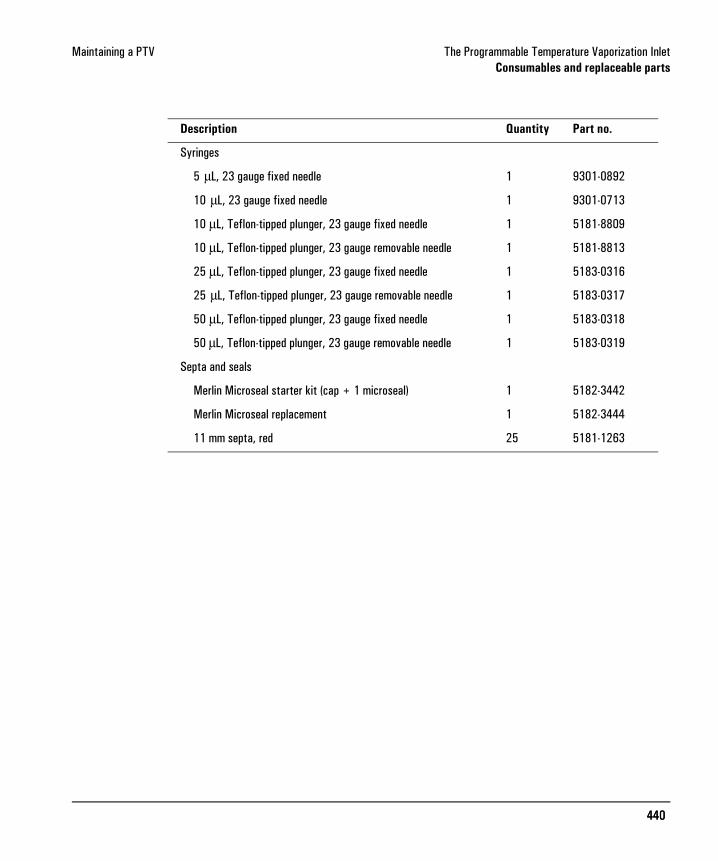
Maintaining a PTV The Programmable Temperature Vaporization InletConsumables and replaceable parts
Description Quantity Part no.
Syringes
5 µL, 23 gauge fixed needle 1 9301-0892
10 µL, 23 gauge fixed needle 1 9301-0713
10 µL, Teflon-tipped plunger, 23 gauge fixed needle 1 5181-8809
10 µL, Teflon-tipped plunger, 23 gauge removable needle 1 5181-8813
25 µL, Teflon-tipped plunger, 23 gauge fixed needle 1 5183-0316
25 µL, Teflon-tipped plunger, 23 gauge removable needle 1 5183-0317
50 µL, Teflon-tipped plunger, 23 gauge fixed needle 1 5183-0318
50 µL, Teflon-tipped plunger, 23 gauge removable needle 1 5183-0319
Septa and seals
Merlin Microseal starter kit (cap + 1 microseal) 1 5182-3442
Merlin Microseal replacement 1 5182-3444
11 mm septa, red 25 5181-1263