Embed Size (px)
Citation preview

REPORT No. 719
THE PROBLEM OF COOLING AN AIR-COOLED CYLINDER ON AN AIRCRAFT ENGINE
By M. J.BREVOORTandU. T.JOYNER
SUMMARY
An analysis ‘ofthe cooling problemshow by what means the cooling of an
ha~ been made toair-cooled aircraft.- “
engine may bt” improced. “Ezch. means of improtingcooling i8 analyzed on the bm”s of e$ectiwmess in cool-ing wn”thre~ect to powerfor cooling.
T%ealtitude problem is analyzedjor both superchargedand unsuperchargedenp”nes. TJwcase of ground coolingis also discussed.
77u heat-transfer process from the hot gases to thecylinder wall is di.scumedon the basis of thefutndumentalsof heat tranefer and thermodynamics.
Adiabatic air-teniperature tie at a stagnation po&tin conqwetwible$OW is shown to depend only on therelocity of$ow.
INTRODUCTION
lV’heuever the cooling of an a.ir-oooled engine cylinderis the factor limiting the power that may be developedin the cylinder, any possible increase in coolhg becom&extremely important. It must not be assumed, how-ever, that doubling or tripling the cooling of an air-cooled engine will in itseIf make possible doubling ortripling the power developed by the engine. If suchan increase in power developed were possible, it couldeasily be obtained from liquid+ooled enginw. Ac-tually, there is no great difference in power developedper cubic inch displacement between good air-cooledand good liquid-cooled enginw
When the cooling of a cylinder is insuilicient, wiyincrease in cooling obtained will make poesible (1) areduction in the fuel consumption of the engine, (2) anincrease in the power that may be taken from theengine, (3) an increase in the time between over-hauls, or (4) a reduction of the likelihood of enginefailure as a result of piston failure or of breakdown of theoil tllrn between the piston and the cylinder.
Various means .of improving the cooling of air-cooledaircraft engines are known. Each method of improv-ing the cooling requires an increase in the power ex-pended for cooling, greater mechanical skill in manu-facture; or both. The various means of improvingcooling are discussed in this report.
Ac
Cp
C*
c,,c.
dD
fJ/
h
HH,
H,/Ap
Ikk.
Lm.,n
;“!lQr
raR
;t
SYMBOLS
cross-sectional area of air passage, nornml to flowvelocity of soundspecific heat at constant prcissurespecific heat at constant volume02,. . . 0=proportionality constantsova-all drag coefficient of airplanecylinder-wall thicknesshydraulic diameter of iir passage
(
4 cross-sectional areawetted perimeter )
()ApD “friction factor —q 47
& eflediveness -.,. -.
surface heat-transfer coefficient, heat units pcrunit surface per degree temperature differenceper unit time
total heat transferred per unit timeenergy 10ss of air occurring up to a given point ..—
in a baflleentigy loss of air occurring up tos a given point
ti a baffle expressed as a fraction of totalenergy loss during passage of air. throughbaffle
indicated horsepowerthermal conductivity of cookmtthernd conductivity ‘of metal used in cylinder
wa& or cooling finslength of air passage, characteristic lengthmponents in the equation connecting NTueselt
number, Prandtl number, and ‘Reynoldsnumber
prcsmrepowerdynamic pressure (1/2 PY2)volume rate of flowradius of curvatureradius from center of cylinder to fin rootReynolds number (DPV/p); compression ratio& spacing “.surface areafin thidnmss ‘ “
T absolute temperature267 -
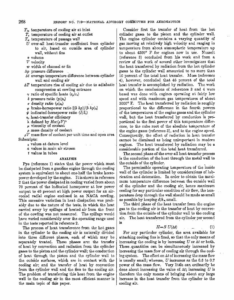
268 REPORT NO”.719-NATIONAL ADVISORY COMM~EE FOR aRoNAu~cs
T,= temperature of cooling air at inletTO temperature of coohng air at outletT. temperature of passage wallU over-all heat-transfer cce.fllcient from cylinder
to air, based on outside area of cylinderwall, without fins
v volumeV velocityw width of channel or M
Ap pressure differenceAt average temperature difference between cylinder
wall and cooling airAT temperature rise of cooling air due to adiabatic
compression at cowling entrancey ratio of specific heats (cP/c,)8 pressure ratio (p/po)u density ratio (P/Po)q brake-horsepower ratio [(b h})/(b’ L&)O]~ indicated-horsepower ratio (1/lJn’ heat-transfer cf%ciencyx defined by Hcc (PV)Ap viscosity of coolantpmass density of coolant
pV mass flow of coolant per unit time and open meaSubscripts:
~ values at datum levela values in main air streamt valuea in tubes
ANALYSIS
Pye (reference 1) shtes that the power which mustbe dissipated from a gasoline engine through the coplingsystem is equivalent to about one-half the brake horse-power developed by We engine.. It is shown in reference2 that the power diesipatcd in cooling varied from about70 percent of the indicated horsepower at low poweroutput to 40 percent at high power output for an air-cooled radial engino enclosed in am NACA cowling.TMs e.-xccssive variation in heat dissipation was prob-ably due to the nature of the tests, in which tho heatcarried away by spilk+ge of heated air from tho frontof the cowling was not measured. The spillage WOUMhave varied considerably over the operating range usedin the tests reported in reference 2.
The process of heat transfe.renco from tho hot gasesin the cylinder to the cooling air is naturally .d”videdinto three Mcrent phases, each of which may beseparately treated, These phases are: the transferof heat by convection and radiation from the cylindergases to the piston and the cylindor wall; the conductionof heat through the piston and the cylincler wall tothe outside surfaces, which arc in contact with thecooling air; and the transfer of heat by convectionfrom the cylinder wall and the fiti to the cooling air.The problem of transferring this heat from the enginewalI to the cooling air in the most efficient manner isthe main topic of this paper.
Consider first the transfer of heat from the hotcylinder gases to the piston and tho cylinder vd.The engine cylinder contains a varying quantity ofgas moving at relatively high velocity ancl ranging intwnpermturc from about atmospheric tcmpcraturc upto almut 4500° F. for engines now in use. Nusselt(reference 3) concluded from his work aml from nreview of the work of several other invcstiga tors thatthe heat transferred by radiation from the hot cylindergases to the cylinder wall amounted to no more than1.0percent of the total heat transfer. Moss (rcferenco4), however, concluded that 40 percent of the totalheat transfer is accomplished by radiation. The workon which the conclusions of rcf erencee 3 and 4 werebased was done with engines operating at fairly lowspeecl and with maximum gas tcrnpcratmes of about3000° F. Tho heat transferred by radiation is roughlyproportional to the difference in the. fourth powersof the temperatures of the cngino gases and the cylim!lcrwall, but the heat transferred by conduction is preport,iomd to the first power of this tmlperature ditTcr-encej to the cube root of the absoluto twnpwature ofthe engine gases (reference 3), and to the engine sped.Consequently, the effect of radiation in heat transfercannot be dismiesed as being unimportant i~~modemengines. The heat transferred by rndiation may bc aconsiderable portion of the total heat transferred.
The second phase of the over-all heat-transfer processis the conduction of tlm heat through the metal waH tothe outside of the cylinder.
The permissible operating temperature of the ‘insidewall of the cyIinder is limitecl by considerations of lub-rication and detonation. In order to obtain tJwmaxi-mum temperature difference between the outside wallof the cylinder ancl the cooling air, hence maximumcooling for any particular condition of uir flow, the temp-erature drop through the walhhould be made as smti]las possible by keeping d/k~small.
The third phase of the heat transfer from the mgincgas to t,~e cooling air is tl~e transfer of hegt by cot~vcc-tion from the outside of the cylinclcr wall to the coolingair. The heat transferred from the cylinder per secondis
H=S i7(At) — (1)
For~ny particular cylinder, the area availablo forattaching cooling fins is fixed, so that the ordy means ofincreasing the cooling is by increasing U or At or both.These ~uantities can be simultaneously increased byincreasing the mass flow of cooling air through the cool-ing system. The effect on At of increasing the mass flowis usually small; whereas, U increases ns the 0.6 to 0.7power of the mass flow. Very little can ordinarily bedone about increasing the v@ue of M; increasing U istherefore the ordy means of bringing about any largeincrease. in the heat transfer from the cylinder to thecooling air.
COOLING AN AIR-COOLED CYLINDER ON AN AIRCRAFI’ ENGINE 269
MEANS OF IMPROVING COOLING
The amount of cooling obtained on a given cylindermay be increased in any of the following ways:
1. By increasing the mass flow of cooling air, leavingthe cykder and the fins unchanged
2. By using metal of higher thermal conductivityfor the construction of the cybnder and the fins
3. By changing the fin design so that the value ofthe over-all heat-transfer coefficient is increased
These three means of improving cooling are discussedin order.
INCREASINGCOOLINGRY INCREASING MASS FLOW OFCOOLINGAIR
The two extreme cases to be considered here are thecases most likely to occur in practical application: (1)The existing operating cylinder temperatures are satis-factory and it is desired to increase the power developed,thereby requiring more heat to be transferred at thesame tern peraturee; and (2) the existing operatingcylinder temperature are too high and it is desired torecluce cylinder temperatures by increasing the massflow of cooling air, the total heat transferred remainingunchanged.
llc.Adams (reference 5, p. 172) gives the relationbetween Nusselt number and Reynolds number for airin turbulent flow as
hD()
__=o.o~o !22 0“8P
(2)
As k is proportional to p, from th”e kinetic theory ofgases, ancl as only small vmiations in k and JJ will beexperienced when the mass flow is changed, k/p0”8maybe considered constant. Then, for any given airpassage,
h=cl(pT~o”8 (3)The over-all heat-transfer coefficient U of equation
(1) may be expressed approximately “h terms of S,, therat io of total cooling surface area to base area; h, thesurface heat-transfer coefficient.; amlfl, the fin effective-ness, m
-u=sJif (4)
For any given lin arrangement, S, is a consta~t andh is given by equation (3).
For values of fl between 0.50 and 0.95, which WOUICIinclude nearly all &s ordinarily used, the exactexpression
~,_ttmh aw— ~w (from reference 6) (5)
may be replnced by the simple appro.simation
f’=1.07–O.30aw (6)where
Equation (6) gives values of j’ within 1 percent ofcorrect over the range stipulated.
W7thin small ranges of variation of~, the value ofj’nay be taken to vary as pV to some power Al,
j’a(pV)” (7)
This power AI varies witl~fl ancl can be shown to be
–0.12Wr
2G ~y~d log.~ @
(8)~,=d log p~”=l 07_0 3W
/mi
. J ~t(pv)’”’
Substitution of equations (3) and (7) in equation (4)
(9)
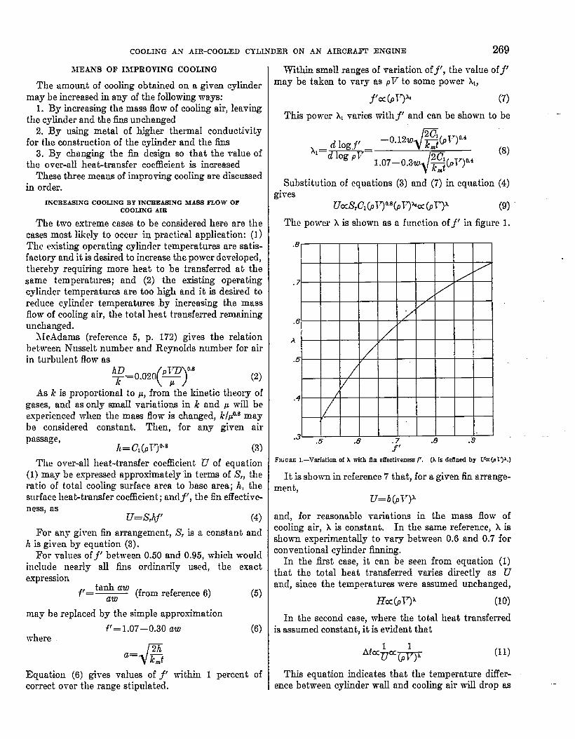
The power A is shown as a function of f‘ in figure 1.
FIGUREl.–VsrIation of Awith fin eflectivenm f’. (k Is deffnedby CrCCCD~3A.)
It is shown in reference 7 that, for a given fin arrange-mentt,
-u=z)(pl’)kand, for reasonable variations in the mass flow ofcooling air, A is constant. In the same reference, x isshown experimentally to vary between 0.6 and 0.7 forconventional c@nder finning.
In the fit case, it can be seen from equation (1)that the total heat transferred varies directly as Uancl, since the temperatures were assumed unchanged,
Ha(pV)~ (10)
In the second case, where the total heat transferredis assumed constant, it is evident that
(11)
This equation indicates that the temperature ditTer-ence between cylinder wall and cooling air will drop as
.-

270 REPORT NO. 71&NATIONAIJ AD \’lSUliYCOMMIITEE FOR AERONAUTICS
the mass Jlow of cooling air is increased, Lower walltemperatures will result from this decrease in At becausethe cooling-air temperature remains unchanged.
Baffle design .—In reference 8, the importance of goodbaffle design in obtaining the largest possible mass flowbetween the iins for a given pressure drop was demon-strated. The air passage formed by the cylinder wall,the fins, and the baffle was shown to be simply a venturi,and the same principles that control venturi designwere employed in obtaining maximum velocity betweenthe h for a given pressure drop.
It was shown in reference 8 how a conventional bafflethen in use could be improved to obtain a 25-percentincrease in mass flow without increasing the pressuredrop. Since P=QAp, this hitirease in mass flow wasobtained with a corresponding increase of 25 percentin the cooling power, for which an increase of 20 to 25percent in total heat transfer was obtained.
For the best arrangement tested in reference 8, 36percent of the total pressure drop ncross the cylinderwas shown to take place in the fis, 50 percent tit thebaJHe exit, and 14 percent at the exit from the exitduct, Only the pressure drop that occurred in the finswas useful in cooling tho cylinder. On many modernengines, the useful pressure drop is only about 20 percentof the tital clrop,
Reference 8 further showed that:1.A good baffle entrance is important and can easily
be attained.2. The baflle should be close fitting. (See table I.)3, The radius of curvature .of the baffle at the baflie
exit should be greater than the fin width. Betz(reference 10) showed that the pressure 10SSwhen airtravels around a, 90° bend is
‘p~=’b’+o’w”’lThis relation shows that the pressure drop for a 90°bend rises sharply as the channel width w increasesrelative h the radius of curvature of the bend r. Theresults from reference 8 (fig. 22 of reference 8 h~ beenreproduced herein as fig. 2) for a finned cylinder with?i-inch iins show the importance of having a fairly largeradius of curvature of the baffle exit.
4. The baffie exit duct should expand gradually, theincluded angle being about 6°. A baffle exit duct 2 or 3inches long gives a largc part of the possible kinetic-energy recovery, Figure 3, obtained from figures 17and 18 of reference 8, shows cooling and baffle conduc-tance as a function of exit-duct length.
6. The baflle-exit cxoss-sectiomd area should beapproximately 1.5times the fnw area between the fins.Decreasing the area of the baffle exit was found to im-prove the cooling at the rear of. the cylinder and increas-ing the area waa found to improve the cooling towardthe front of the cylinder.
The results of cooling tests on a variety of baillearrrmgementa and on finned cylinders with streamline
1.a
.8
$“4-,&-
.2
0
— .5 I I I 2!0Baffle concfucr’once
~ -
.4~ ~ !.6
1 ‘
L ~
/
/ ‘.3 /.27.
“+$..
.2 .8$
,1 .4
n t o
Baffle radius; in.
Fmuw 2.–Effect ofbaf!leradlrrson IIr/Ap, ba!lleconductarrcqand molingat M&’fromfrontofoylinderat optimumaxit-duetopxdng. Domeex[topenfng,1,0Inch;exlt+hrctlength, 7.00inches;cylfnderdiar.utter,4.66hich~ fln spacaj H6 inch:flrrwid~ M Inch. (Reproducedfromreferanca8.)
—Exif - duct length, in
FIGUIZES.—Effectofexit-ductlength on caollngand Mile crmductanmat 16CFfromfront of.cylfnderat optimum exit-ductopenfrrg. Beffleexit openin&I.&lfnehe$oylfnderdkneter, 4&9lnche&fin epacq Jfo lnomflnwidth, MInch. (Data fromrefaranmQ
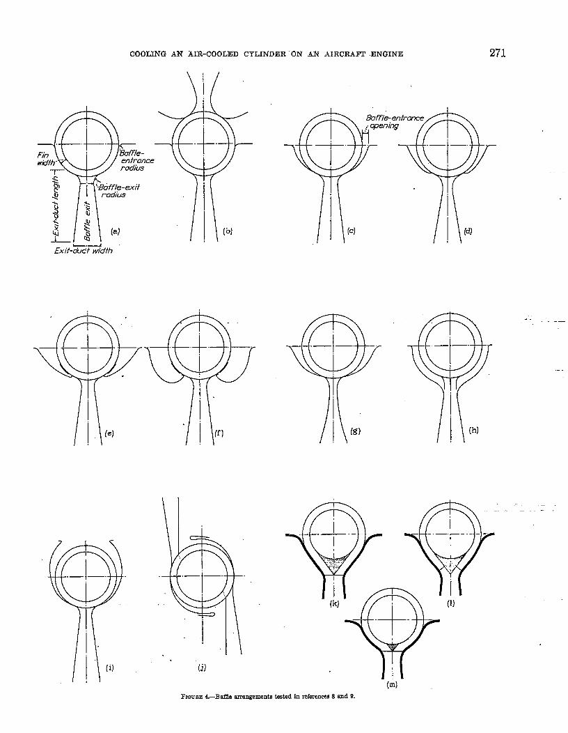
exits are given in table I. The cylinder &d tho baffiearrangements tested are shown in figure 4. Thesketahes in figures 4 (a) to 4 (j) are reproduced fromfigure z of reference 8. The test data for these arrange-ments are reproduced in table I from the tuble inreference 8. The arrangements showu as figures 4 (k)to 4 (m) are reproduced from figure 3 of reference 9.
It should be noted that, although these tests weremade on a model of a cylinder barrel, the same generalprinciples apply to the cooling of the head.
Bdlks designed on the basis of the results given inreference 8 have improved the cooling on a completoengine 28 percent over that obtained on an engine withconventional bafiles, which had about %-inch clearancebetween &s and baffle and a very short exit duct.
The application of the results from reference 8 tofull-scale engines is given in reference 11.
COOLING AN AIR-COOLED CYLINDER ON AN AIRCRAFT ENGINE 271
Fin
$ ~<
L.-Exif-&tcf widfh
.
,
\
(j)
—
FIGCBEL—Ba13earrangementstested In references8 end 9.
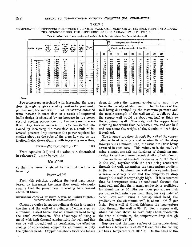
272 REPORT NO. 7l~NATIONAL ADVISORY COMMITTEE FOR AERONAUTICS
TABLE 1
TEMPERATURE DIFFERENCE BETWEEN CYLINDER WALL AND INLET AIR AT SEVERAL POSITIONS AROUNDTHE CYLINDER FOR THE DIFFERENT BAFFLE ARRANGEMENTS TESTED
[Data forbafdes1to 15taken fromreferencf8, and data forbadlesLOto18taken fromfigure4 ofrcfemnca9]
.i..i---- “0.25
11.26
40 .764a . 7b4U .254a .264C .75
; ~{ ;;
4 .754 .764)4 :;:4
t
-------4) . . . ..-.4) -------4 m) ------
.+B~~te-
width(fU.)
L876
;;;’
1:876L250L2531.2m;. ~w
1:ml
;%1.2/4.7SI
.- . . ..--.------.-----
0.25
1I111
.‘m1.001.00
i%1.23.75
1.26.62
—----
,.
EsIt-dactength(in.)
0077
:77777
;77
.-----....... ......... ..... —-----
I 1-.=
Exft-~ ~ Tamrqatura dIfferericer F). .
duct Flared‘?AAy to (h.) _
T.0
.------ ------- . &a------- . .. -----2.62 . . . . . . . . z2.23 . . . . . . . . ml2.62 . . . . . . . . 1262.62 -------- m$g ;::::::: g
a62 -------- 1322.25 . ------- ml!A26 --i-a-. 1412.262.02 .-...-. %2.25 . . . . . . . . 1631.25 -------- lk2
-----.- ---------------------- %. . ----- . . . . . . . . S3
flow through a given cooling unit,—As previouslypointed out, the increase in heat transferred obtainedfrom increase in mass flow as a result of improvcclbaffle design is attended by an increase in the powercost of cooIing proportional to the increase in massflow. Any further increase in heat transferred ob-tained by increasing the mass flow as a result of in-creased pressure drop increases the power required forcooling about as the cube of the mass flow or, as thefriction factor drops slightly with increasing mass flow,
Power= QApoc(pk’)Apa (pV)ze (12)
From equation (10) and tho value of h determinedin reference 7, it may be seen that
Ha (pV)0.65
so that the power is related to the tottil heat trans-ferred by
Power aH4,4b
From this relation, doubling the total heat trans-ferred by increasing the mass flow would obviouslyrequire that the power used in cooling be increasedabout 20 times.
INCREASING’ COOLING BY USING METAL OF HIGHER THERMALCONDUCTIVITYIN CYLINDERHEAD
Current practice in engine-cylinder design is to makethe fins and the wall of a cylinder of either steeI oraluminum, a steel barrel and an aluminum head beingthe usual combination. The advamtage of using ametal with high thermal conductivity for wall and finscan be well brought out by considering the effect oncooling of substituting copper for aluminum in onlythe cylinder head, Copper has about twice the tensile
~Angularpmlt!onaroundcgllnder(deg)-
11411410610611411411010812011712811610bla)lx
m100
.-
-60
110110ml103109110103103117116
H
:E132WJw93
.w
—
116113
18112112108108124EMU7120lo616013092WI91
—
—10b
—
1241191031061151181101121271.2612.S125Xll1s)1409391
-----—
ml
182m108110ml122114114120123312?!1’23114147133
%91
— ‘1136 MI
139 160132114 iillb 122w 13317A 136116 lZI117m ;:120rm :%m In116, 120146 149127w -5
103 m102 m
163
1001461361%141140120126136
%
L?164m102124106
lW
MalM144lkalbl147134132142m132164130led13J
134104
—
1Cloea
Power increase associated with increasing the mass strength, twice the thermal conductivity, and threetimes the densi~y of aluminum. The thickness of thewall being determined by the maximum pressure andthe tensile strength” of the wall metal, it follows thatthe copper wall would be about one-half as thick asthe ahuninum wall. The weight of the copper headincluding fins would then be between one and one-halfand two times the weight of the aluminum head thatit replacecl.
The temperature drop through the wall of the coppercylinder head is only about one-fourth of the dropthrough the aluminum head, the same heat flow beingassumed in each case. This reduction is the result ofusing a metal one-half the thickness of aluminum andhaving twice the thwmal conductivity of aluminum.
The coefficient of thermal conductivity of the mctulin the wall, together with the heat being conductrdthrough the wall, cletermines the temperature gradientin the WUI1. The aluminum wall of the cylinder headis made relatively thick and the temperature dropthrough the wail is surprisingly high. If it is assumedthat 35 horsepower must be conclucted through thehead wall and that the thermal conductivity coefficientfor aluminum is 10 Btu per hour per square inchper d&ree Fahrenheit per inch, then, for a cylinder of6-inch bore and having a hemispherical head, thegradient in the aluminum wail is about 157° F perinch. For a wall of Jf-inch thickness the temperaturedrop through the wall is 98° F. For a copper wall,which has been shown to havo only about on~fourththe drop of aluminum, the temperature drop thro.ghthe waU is onIy 25° F.
Suppose that the inner surface of the cylinder-headwall has a temperature of 500° F and that the comingair has a temperature of 100° F. On t,ho l.msis of the
COOLING AN AIR-COOLED CYLINDER ON AN AIRCRAFT ENGINE 273
temperature drop through the ywll just mentioned, thetemperature difference between the cooling air and theoutside surface of the cylinder-head wail is 302° F forthe aluminum head and 375° F for the copper head.These temperature dfierances indicate that the copperhead would obviously dissipate about 25 percent moreheat than the aluminum head, the same fin effectivenessbeing assumed. The substitution of copper for alumi-num in the fins, however, considerably increas~ thevalue of the h effactiveness (reference 6). On finssuch as are now in use, for example, about 0.050 to0.090 inch thick and 1.5 inches wide, the substitution ofcopper for aluminum would increase the effectivenessby about 10 percent. The total effect of substitutingcopper for aluminum is, according to the precedingrough calculation, to increase the cooling on the headby 27 percent.
The aluminum head, exclusive of valves and otherconnections, weighs approximately 5 pounds. Thisweight would be increased to 8 or 10 pounds by using acopper head. The power required to transport thisincrease in weight is small if the increase in cooIingobtained is considered.
Application of the foregoing considerations wouldrequire the development of suitable alloys or pro-tective coatings.
INCREASINGCOOLfNGBY IMPROVING THE PIN DESIGN
lt has been shown in a previous section that the
cooling of a cylinder could be increased as much asdesired by sul%ciently increasing the mass flow ofcoohg air. The cooling can also be increased byimproved finning. Increased cooling by increased massflow was also showm to be obtainable at a relativelylmge increase in power for cooling. Improved finningwill also require an increase in power for cooling, butthe extra power is used for cooling with relatively highefficiency.
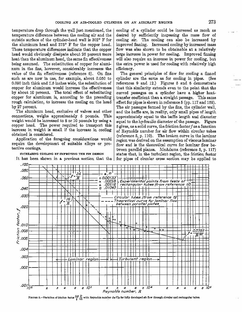
The general principles of flow for cooling a finnedcylinder are the same as for cooling in pip-. (Seereferences 9 and 12.) Figures 5 and 6 demonstratethat this similarity extends even to the point that thecurved passages on a cylinder have a higher heat-transfer coefllcient than a straight passage. This sameeffect for pipes is show in reference 5 (pp. 117 and 159).The air passages formed by the iins, the cylincler wall,and the baffle are, in reality, only small pipes of lengthapproximately equal to the baffle length and diameterequal to the hydraulic diameter of the passage. Fiiure5 gives, as a solid curve, the friction factorj as t-tfunctionof Reynolds number for air flow within circular tubes(reference 5, p. 110). The broken curve in the lmni.narregion was derived on the assumption of viscous laminmflow and is the theoretical curve for laminar flow be-tween parallel planes.. McAdams (reference 5, p. 117)states that, in the turbulent region, the friction factorfor pipes of circular cross section may be applied to
.100
.080
.060
.040
.030
.020 ‘x I I I-------- ,=-. ----- ~. ____
1 I I I I I I I I I I I%1 II llllllllllw’~ Illtlllllll 1
1, .–1 I Ill Ill
----<: LuminOr r
.W2 I I I
.q&_uJMwJz 34 6 8 103 8 104 2 34
R~ynol;s n;mber~ R6 8 105
AP D ~lth ~emolb ~mMr DpVIPfmfu!lydevelopedalr flowthrough~r~~ ~d r~tQ@m ‘Ub=.FIOURE6.-Varfat1onet frfctlonfactm —g 4X

274 REPORT hm. 71*NATIONAL ADVISORY cOMMITTEE FOR, AERONAUTICS
tubes of any cross section, provided that the hydraulicdiameter of the tube is used in place of the diameter ofthe circular pipe. Points obtained from tests (refer-ence 12) on Wgmente of finned cylinders with variousfin spacings are also shown in figure 5. The rgmementbetween these points and the curve for pipes of circularcross section is good, especially in the turbulent region,and cooling is almost invmiably accomplished in thisregion. It must be recognized that the pressure dropcalculated from the curve in flgurk 5’is the drop occur-ring wide the air is passing between the fins. If theseresults me to be applied to an engine cylinder, the exitloss must be adclcd. This loss is controlled largely bythe baffle design, which has been previously discussed.
Reference 13 gives tho relation for th’e over-all heat-t,mnsfer coefficient bnsed on cylinder-wdl nre~ M
“=*[:(’+%)t”n’iaw+’l“3)where
The coefficient U may be computed ns a function offin spacing, h width, thermal conductivity of the fins,and surface heat-transfer coefficient h, which may becalculated from the Nuwelt number. Figure 6 gives
‘l@ ,? .34
Reynoldss nuk%, pVD/~”34 6.
FIQUEE6.—Variettonof Nnsseltnumber with Reynoldsnum~ foraevaIrJfiWdJUm
the Nusselt number as a function of Reynolds numberfor curved segments of finned cyhnders with severalfin spacings. The curve for fylly developed turbulentflow within tubes (from reference 5, p. 172) is inclucled
for comparison. I?igu+e 7 shows, for a steel cylinder,values of U so camputed plotted against g for a comtantair speed of 100 miles per hour between th~ fins. Eachcurve is for a particular fin width, In all cases., tho finthickness is optimum.
o .02 .04 .0: in .LM .fi7 .12:s.
-.
.
—
FIGURE7,-Vadation of ovar+ll heat-tranaferccmllcfeptwith spacingfor four finwidths, at lW milespar hour and optfmum13ntbfckness. Steelcyllmfer;k_=2. 17Btn /(hrJ”(Win.) (“F/In.).
..iFigure 8 shows a similar set of cuti& for Stcrl,
aluminum, and copper fins. These curves Low theultimate heat transfer that can be obtained by the uscof mderisl of high thermal conductivity. This ml-vanta@ of, high thermal conductivity is in addition tothat previously considered where only the effect of theternpe~?ture drop through the wall upon the temper-ature, difference between outer cylinder surface nndcooling ajr was considered.
The variation of cooling-air find cylincler-wrdl tcm-peratti& with the length of air passnge is shown iuf@re”9 for the condition of constant head. transfw por ““
unit ptissage length. This condition .~. nmrly tlmtprevdng on an air-coolecl engine cylinder. Note thaL,for thii condition, the temperature difleronce betweenthe cylinder wall and. the cooling air is constant alongthe passage length. Hence, it follows tkt any increasein the, temperature rise of the cooling nir in its passngearound the cylinder will result in increascfl ~r~ll-tem-perature variation around the cylinder.

CQOLING .AN AIR-COOLED CYLINDER ON AN. AlRCR4.l?T.ENGINE 275.
k“\c..
$\3
GS
o .02 .04 .08 .08 ./0 .12s, o-t.
FIGWEE&-Varfatfon of ow?i+allherd-transferccellldent with S- for thrwthermalconductiv!tfee,at 100MIIeeperhourand optbmuntin thfekness. W,1Inch.
Greater temperature rise of the coobg air will resdtfrom a decrease in fm spacing, wiles the mass flow ofcooling air is maintained by either reducing the bafflelength or increasing the pressure drop available forcooling. If the mass flow of cooling air is maintainedby either of these methods, then a change b smallerfin spacing wiU reduce cylinder-wall temperatures at allpoints in the baffle with a small increase in wall-tem-perature variation around the cylinder.
If the heat-transfer coefficient of a cylinder is in-
FIOUEB9.—Varfntfonof coollng-alrand cglfnder-wdl tempemdnreaalong an-airpassagefor the condftionof @stant heat transfer per unft paasagelength.
creased by increasing the mass flow of cooling air, thenthe temperature rise of the cooling air, and hence thewall-temperature variation, will become smaller. Thisprocedure -will also reduce cylinder-walI temperaturein the baffle but, as has been pointed out, will require aconsiderable increase in power consumed for coolhg.
The power for any pa.rticulnr arrangement can becalculated from
POWer=A17Ap
sinco Ap and A will be known rtnd ~7can be cdmhatedfrom the equation relnting pressure gradient to Reynoldsnumber for turbulent flow (reference 5, p. 111):
(14)
Although the power increases faster than the heattransfer, decreasing the spacing is still au economicalmeans of improving the cooling if mmmfticturing dii%-culties me neglected.
FRONT COOLING
Cooling on the front of the cylinder of an air-cooleclradial engine is accomplished by large-scale turbulence,as first mentioned in reference 14; the subject has beencovered in reference 15 and will not be reviewed here.SufEce it to say that front cookg has proved entirelyadequate in the past and, with some improvement infin design, will probably be adequate for future needs.
,.GROUND COOLING
h airplane engine must be supplied with sufficientcooling for any required condition of operation. Thedefinition of these conditions in flight is relativelysimple because there both the cooling requirements rmdthe cooling available can be M.nitely stated. It issometinm dif%cult to meet certain arbitrary coolingrequirements on the ground, as, for instance, that theengine cool with a c&-tain fraction of full power.
Such requirements can invariably be met on anyengine type by penalizing the airplane with extra weightor poor performance in flight. The analysis of twoextreme cases is enlightening: (1) an engine required tocool with reduced power, and (2) an engine required toCOOI with fll~ pOW&. -
Based on the experimental workcotita.nt cylinder temperatures,
1 1.76
()AP=APl ~
—
of referenca 2, for
(15)
where Ap is the req+ired pressure drop “for satisfa~tolTcooling for a given jndicated horsepower .1, ancl Apl-isthe known pressure drop for satisfacto~ cooling atsome other indicated horsepower Il. TV’hen the enginewas operating at full power, Apl was assumed to be 40pounds PW square foot and 11 to be 1100 horsepower.
276 REPORT NO. 71%NATIONAL ADVISORY COMMITTEE FOR AERONAUTICS
If the engine is operated at one-half top speed, I iscalculated to be about 150 horsepower and equation(16) gives the required Ap as 1.2 pounds per square foot.This pressure drop can be obtained by proper de.+ign.
If the engine requires a pressure drop of 40 poundsper square foot for cooling at full power in fllght,approximately this same pressure drop will be requiredon the ground. The problem is simply one of provid-ing a pressure drop of 40 pounds per square foot across.the engine. Two methods for the solution of thisprobkun are obvious: (1) T~ provide the requiredpressure by means of the propeller and its slipstream;and (2) to use auxiliary means, such as a blower.
The use of the propeller and the propeller slipstreamfor cooling has been investigated in references 16 and] 7. In reference 17, the nature of the flow in front ofthe cowling was studied. A round-edge disk was set inthe front of the cowling and it was shown that anannular opening bet wean the disk arid the cowling forthe entry of the air would ..materially increase thepressure drop for cooIing. The amount of increasedepended upon the blade-angle setting and the solidityof the portion of the propeller operating in front of thisannular opening. Obviously, both the nose of thecowling and the disk must be .gJose to the propeller formaximum pressure. The thrust-distribution curvesfor various propellws give a clear picture of the functionof tho propeIkr in providing p-esaure drop for cooling.The maximum pressure occurs near the 0.6 radiuspoint; the difficulty of yrovid~g adequate pressuredrop for cooling at full power on the ground when thecowling d~ameter is small @ative to the propellerdiameter is obvious. Propellers with blade sectionsextending to the hub markedly increase the pressuredrop available for coding provided that the bladeangle of the propeller is suitable for the local velocity,Propellers having round blade shadca near the hub maybe equipped with sleeves having airfoiI sections to givethe same result. Suction at the exit slot is provided byflaps, which operate on the propeller slipstream. Theeffectiveness of flaps depends almost entirely upontheir being located in a relatively high velocity.
The previously discussed conventional means ofaugmenting the cooling ~re usually suflic.ient to provideadequate cooling for most ordinary cooling conditions.In the. future, however, cams may very possibly occurwhere these conventional means may fail to provideadequate cooling. It will then be necessary to resortto blower cooling.
Tho efficiency of the blower will be about 70 percentfor a good design. For the. 1100-horsepower engineassumed, approximately 11 horsepower of useful workwill be required to cool the engine. At 70-percentefficiency, this value amounk to a power expenditureof about 15 horsepower” for ground cooIing, Au excesspressure wilI be supplied when there is any air speed.This. excess pressure can be used to force air out the
exit slot at an increased speed and thus, as the exitslot is ahnost 100 percent efficient, the excess workwill be recovered. The only 10SS, then, is that duo tothe inefficiency of the blower.
The main consideration in the use of blower coolingconcerns mechanical diflimlties, weight, and effect ofblower cooling on the front oooling as gpposed to thedMculty, for ordinary cowlings, of producing sufficientpressure drop for full-power cooling on the ground withlargeAiameter propellers on normal-size cowlings.
Two conditions of ground cooling have been discussed,namely, with the engine idling and at full power, Thediscussion has shown that certain means are availablefor giving cooling on the ground. Each of these moansmust be examined in the light of whut a particularmethod of improving cooling does to the airplaneperformance. When this examination is concluded, itmay very possibly be more practicnble to alter thecooling requirement by restricting operation on thoground and during take-off than to take the penaltyin performance. From considerations of economy andsimplicity, every detail of cowling, flaps, and propellershould obviously be arranged ti give maximum oooling;only then, if the cooling is insufficient, should blowercooling be resorted to.
PRESSURE AVAILABLEFOR COOLING
The pressure available for cooling with a conventionalcowling has been the subjeet of several studies (refer-ences 14, 16, 17, and 18). These studies, which coverthe whole range of operation from ground h cruisingcondition, show the fundame.nhd principks involvedin the problem and give information suitable for de-sign purposes.
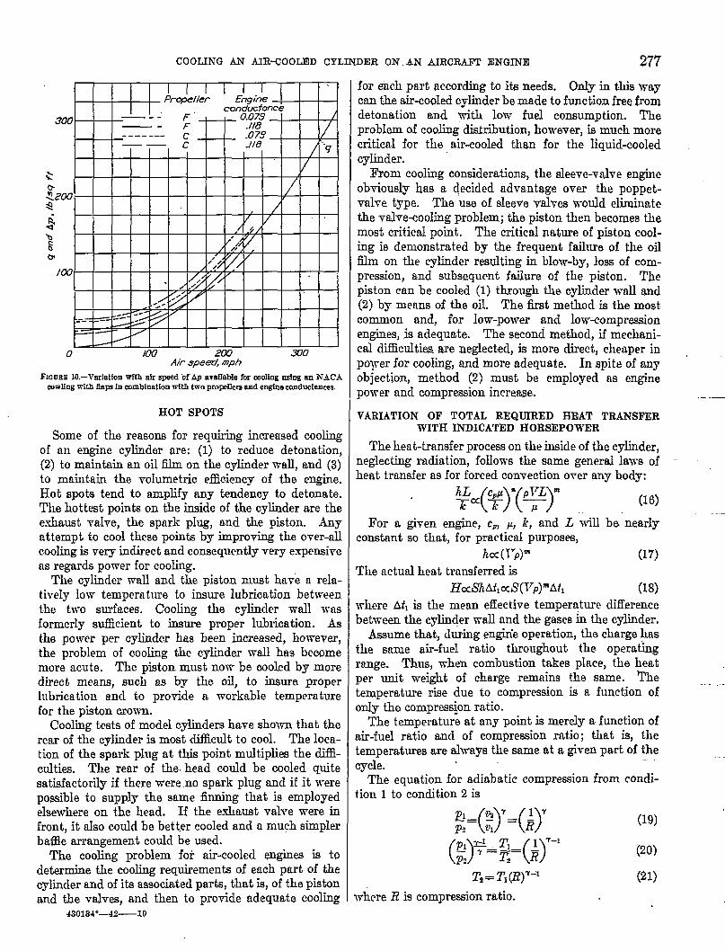
The pressure on the ground being entirely dependenton the slipstream from the propeller, the+ distributionof the velocity in this slipstream determines the premureavailable for cooling. An understanding of this factimmediately explains the variation in pressure avrtilablofrom propellers of various designs and diamete~. Someof these variations are illustrated by figure 10 whoreAp available for cooling is plotted against air speed.Dyntirnio pressure q is also shown as a function of airspeed. Curves for two engine conduckmces are givenfor two typical three-blade propellers having diametersof ltiet. Propeller F is Bureau of Aeronautics planform 4893 and prope~er C is Bureau of Aeronauticsplan form 5868-9. The nacelle was 52 inohea in diam-eter. In the computation of these curves, the enginewas assumed to be developing 75o horsepower,
The curves for propeller 1?, which has airfoil sectionsclose to the hub, may be used almost regardless ofrelative diametir of nacelle and propeller as long as the
propeller disk loading remains the same, Propeller C,however, which has round blade shanks near the hub,will give a lower Ap if the propeller diameter is in-creased relative to the nacelle diameter or vice versa.
COOLING A.N AIR-COOLED CYLINDER ON All AIRCRAFT ENGINE 277
I I I IPrapeIler Ehgi*
cunduc fanee300
—.. F /—. < ~ ‘%9
f). o I /------- .u/.J /—— k .!18 ‘qI
I 1 /
/09 I 1 I I I I A
. M’5
/ I I I I I I I I I
1
2LW 3/70Air speed, mph
FIGURE10.—l”erIatIonwfth slr speed of Ap avs.IIablefor mollngusing sn NAC.4wwlhgwith flapsIn combinationtith two prorelleresnd engineeonductsnms.
HOT SPOTS
Some of tho reasons for requiring increased coolingof an engine cylinder me: (1) to reduce detonation,(2) to maintain an oil film on the cylinder -ivdl, and (3)to maintain the volumetric efficiency of the engine.Hot spots tend to amplify any tendency to detonate.The hottest points on the inside of the cylinder are theexhaust va.lve, the spark plug, and the piston. Anyattempt to cool these points by improving the over-allcooling is very indirect cmd consequently very expensivem regards power for coohg.
The cylinder wall and the piston must have a rela-t ively low temperature to insure lubrication betweenthe two surfaces. Cooling the cylinder vvall vmsformerly sufficient to insure proper lubrication. Asthe power per cylinder has been increased, however,the problem of cooling the cylinder wall has becomemore acute. The piston must now be moled by moredirect means, such as by the oil, to insure properlubrication and to provide a workable temperaturefor the piston crown.
Cooling tests of model cylinders have shown that therear of the cylinder is most diilicult to cool. The loca-tion of the spark plug at this point multiplies the dii%-culties. The rear of the. head could be cooled. quitesatisfactorily if there were no spark plug tmd if it werepossible to supply the same finning that is employedelsewhere on the head. If the exhaust valve were infront, it also could be better cooled and a much simplerbaffle arrangement could be used.
The cooling problem foi air-cooled enginEs is todetermine the cooling requiremem% of each part of thecylinder and of its associated parts, that is, of the pistonand the valves, and then to provide adequate cooling
430134”-42—-10
for eimh part according to itis needs. Only in this waycan the air-cooled cylinder be made to function free fromdetonation and ~th low fuel consumption. Theproblem of cooling distribution, however, is much morecritical for the air-cooled than for the liquid-cooledcylinder.
From cooling considerations, the sleeve-valve engineobviously has a decided advantage over the poppet-valve type. The use of sleeve valves would eliminatetie valve-cooling problem; the piston then becomes themost critical point. The critical nature of piston cool-ing is demonstrate ed by the frequent failure of the oilfilm on the cylinder resulting in blow-by, loss of com-pression, and subsequent failure of the piston. Thepiston can be cooled (1)through the cylinder wall and(2)by means of the oil. The &t method is the mostcommon and, for low-power and low-compressionengines, is adequate. The second method, if mechani-cal dficulties are neglected, is more direct, cheaper inpoywr for cooling, and more adequate. In spite of anyobjection, method (2) must be employed as enginepower and compression increase.
VARIATION OF TOTAL REQUIRED HEAT TRANSFERWITH INDICATED HORSEPOWER
The heat-transfer process on the inside of the cylinder,neglecting radiation, follows the same general laws ofheat transfer as for forced convection over any body:
W)’(%7 (16)
For a given engine, CP, p, k, and L will be nearlyconsttmt so that, for practical purposes,
ha(l”p)~ (17)
The actual heat transferred is
lZCAhAtlCCiS(l’P)=Atl (18)
where Atl is the mean effective temperature differencebetween the cylinder wall and the gases in the cylinder.
Assume that., during enghfe operation, the charge hasthe same air-fuel ratio throughout the. operahgrange. Thus, when combustion takes place, the heatper unit weight of charge remains the same. ‘Thetemperature rise due to compression is a function ofonly the compre+on ratio.
The temperature at any point is merely a function ofair-fuel ratio and of comprewion ratio; that is, thetemperatures are tdways the same at a given part of thecycle.
The equation for adinbatic compression from condi-tion 1 to condition 2 is
T*= T, (l?)’-’ (21)
where R is compression ratio.
.—

278 mzPoRT NO. 719-NATIONAL ADVISORY COW-MITTEE FOR AERONAUTICS...
Equation (21) shows that the temperature T2 re-mains the same regardless of quantity of charge for agiven compression ratio and air-fuel ratio.
The velocity of movement of the charge in thecyliider is proportional to the speed of the engine.The density of the charge is directIy proportional to thecharge present which, in turn, ip proportional to theindicated horsepower. (See reference 1.) The value ofthe heaMranefer exponent m for turbulent flow usuallyft-ills in the. neighborhood of 0.8.
For convenience, consider two casea: (1) an engineoperating at constant speed but with variable powerdue to variation in weight of charge, and (2) an enginehaving constant charge per cycle but with varyingspeed.
It is to be remembered that, in both cases, the tem-perature of the gases in the cylinder is fixed by theengine,
In case .(1), the velocity and the temperature arefixed and the heat dissipated is proportional to p“8 orloos. In case (2), the temperature and the density rc-ma.in constant and the heat dissipation depends uponVus or (rpm) &S. The indicated homepower isproportional to the engine speed, Thus, the heat dis-sipated is proportional to FE.
It follows that, regardlew of whether the power iswmied by changing engine speed or charge weight, theheat to be dissipated is proportional to 1°.8.
This conclusion is in agreement with experimentaldata obtained by Pye (reference 1), which showedthat
l?ccl~ (22)
I%ikel (reference 7) obtained values of 0.64 to 0.68for the exponent of 1 in tests on cylinder heads ancl0.64 to 0.85 in tests on cyli.ndar barrels.
As a further check on the foregoing conclusions, theexperimental work of referuce 2 gave the empirimdequation for pressure needed for cooling
Reference 12 gives
where J’ ii-the air velocity between the fins.
(15)
(23j
(24)
As the cylinder temperature= were held constant inthe work described in reference 2, it follows that
(25)
This subject has been treated in reference 19 inwhich similar conclusions were reached.
THE EFFECT OF ALTITUDE ON COOLING REQUIRE.MENT FOR AN UNSUPERCHARGED ENGINE
The cooling on a cylinder being dependent on thetemperature and the density of the cooling air and onthe pressure drop available for cooIin& changes inaltitude may have a great eflect on cooling. !l%~effect of aItitude on cooling will now be considered.
Assume that CD is constant with changes in aItitudeand further assume that the engiile power P developedat any altitude is defined by
P=pPo (26)
1.6
1.5
f. 4 I /
FIGUREll,–-Vsrfat[onw“ttbaltknde ofss%al performtics and Molfngpsrsnwtersforan afrplanehavingan unaupmh.rged engina.
In figure 11, q is shown as a function of altitude (dataobtained from reference I.),
These assumptions are sufficiently accurate for usein calcdating cooling parameters.
COOLING AN AIR-COOLED
Equating engine thrust power to airplanepower,
P= Cllqasvfrom which it maybe shown that
()p1~P2~ 2 2~Q=T Z5S
andq“=a1~p21s(c&
Solving equation (29) for V yieIds
v=p113/#q’4
CYLINDER ON AN AIRCRAFT’31NGINE 279, .
drag
(27)
(28)
(29)
(30)
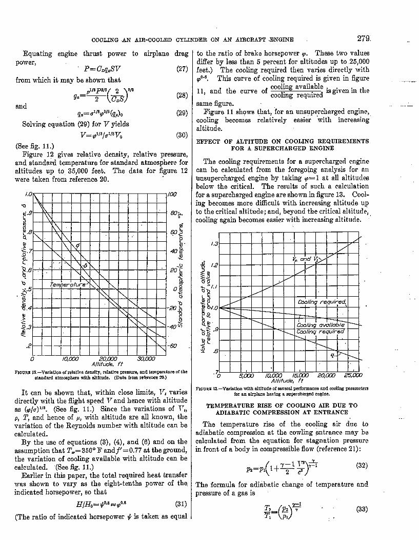
(See fig. 11.)Fi~-re 12 gives relative density, relative pressure,
rtnd standard temperature for standmd atmosphere fornltitudes up to 35,000 feet. The data for figure 12were taken from reference 20,
0 Io,cKw .Zwo m,mAliitude, ft
FIGURE12.—Varfatfonofrefatlre densfty,reIrdIrePreamr%and temperatureofthestandard atmospherewith altltnde. (Data from referenm93.)
It can be show-n that, within close limits, 17, -rariwdirectly with the flight speed T7and hence with altitudeas (p/a) 1’8. (See fig. I I.) Since the variations of Vt,p, T, and hence of P, with altitude are all known, thevnriation of the Reynolds number with altitude can becalmdated.
By the use of equations (3), (4), and (6) and on theassumption that Tw= 350° F andfl= 0.77 at the ground,the vmiation of cooling available with altitude can becalculated. ‘(See fig. 11.)
Earlier in this paper, the total required heat transferwas shown to vary as the eight-tenths power of the.indicated horsepower, so that
HIHO= $0.8=pox (31)
(The ratio of indicated horsepower Y is taken as equal
to the ratio of brake horsepower p. These two valuesd.ifler by less than 5 percent for altitudes up to 25,000feet.) The cooling required then varies directly with
O.s. This curve of coohng required is given in figureP ____
11, and the curve of ,~& ~q~~~ is given in the
same figure.
F~ure 11 shows that, for an unsuperchmged engine,cooIing becomes relat,ively eaaier “with increasing”altitude.
EFFECT OF ALTITUDE ON COOLING REQUIREMENTSFOR A SUPERCHARGED ENGINE
The cooling requirements for a supercharged enginecan bc calculated from the foregoing analysis for mnunsupercharged engine by taking p= 1 at all altitudesbelow the critical. The results of such a calculationfor a supercharged engine are shown in figure 13. Cool-ing becomes more difficult with increasing altitude upto the critical altitude; and, beyond the critical altitucle,cooling again becomes easier with increasing altitude.
~GuaE lS.—Varf8t!onwfth altitude ofasmrfdperformanceand cdfng parametersfor an alrpkmehaving a auperchammdengfne.
TEMPERATURE RISE OF COOLING AIR DUE TOADIABATIC COMPRESSION AT ENTRANCE
The temperature rise of the cooling air due toadiabatic compression at the cowling entrance mny becalculated from the equation for stagnation pressurein front of a body in compressible flow (reference 21):
The formula for adiabatic changepreswre of a gas is
()T~_ ~ ~~~1— PI
of temperature and
. . (33). .

280
where pvc
T
REP6RT “NO. 719—NATIONAL ADVISQRY COMMI~EE- FOR AERONAUTI@ . .
absolute prawure .-airplane speedvelocity of sound at altitude at which airplane
is flyingabsolute temperature
Subscript 1 refers to the free air stream at the flyingaltitude. Subscript 2 refers to air conditions. in thecowling entrance. Combining equations (32) and (33)gives
from which
(34)
(35)
Laplace’s formula for the velocity of sound in a gasgive9
(36)
When equation (36) is substituted in (35) am?, since~=cP/c,, the equation becomes
Since pV=p/P=RT for one slug ofcp—c.=.R for one slug of substance,
(37)
substance and
(38)
where Al’ degrees FahrenheitV feet per secondc. Btu & slug per degree Fahrenheit (7,73 for
air)Equation (38) shows that, for adiabatic compressible
flow under standard conditions, the temperature rise ofthe cooling air at the entrance is a function of velocityand specific heat and is independent of altitude. Thistemperature rise can be calculated for the anticipatedtop speed of the airplane and allowance for it can bemade in the design calculatio~.
VaIues of AT have been calculated and are shownfor several values of V in table II.
TABLE II
ADIABATIC TEMPERATURE RISE AT ANY STAGNA-TION” POINT DUE TO THE FORWARD VELOCITYOF THE AIRPLANE
I 1. r
I (m~h) I .@; .
1-1 ...ml ‘. 1.8
i% 1:?400 ,!af!WI 44.eem 64.2
CONCLUSIONS
The problem of cooling an air-cooled cylinder of anfiircraft engine has been analyied. The cooling maybeimproved by:
(1) Increasing the mass flow, Doubling tho coolingrequires 20 times the power for cooling,
(2)””Improving the fin design. Wider fins give in-creased cooling with a power increase for cooling pro-portional to the width, Reducing the fin spacing by
I one-half its value gives about a 50-percent increase incooling and t-t100-percent increase in power for cooIingif the length<iarneter ratio of the air passage is keptconstant and the fin thickm%s is kept optimum.
(3)-”TJsing a material of higher tlwrmrd conductivity.The temperature drop through the cylinder wall may hedecreased, thus giving better cooling without change ofother conditions.
The problem of ground cooling was reviewed fromconsiderations of the cool$g requirements and of themeans by which such requirements can be met, It wwconcluded that, for normal operation of landplancs, sat-isfactcny cooling could be obtained by the use of pro-peller and cowling flaps and that seaplanes with longtake-offs would undoubtedly require auxilimy means ofcooling.
The mechrmism of heat transfer from hot gases tothe cylinder wall was analyzed on the basis of thmno-dynwnics, and the hcnt transferred wns shown to bcprop@tional to the cig~~t-tenths power of the indicatedhorsepower, regardless of whether the horsepower wasvaried by changing the cylinder chmge or by varyingthe engine speed.
The cooling problem at altitude for an unaupcr-charged and a supercharged engine hns been analyzed.It was shown that the cooling is:
(1) Accomplishcd at altitude without change in powerfor cding or fin design for an unsupc+rcharged eng+ne.(2)More dil%cult, up to critical altitude, for a super-
charged enghm. An nrra.ngement that just cools satis___factoriIy on the ground would have approximately a10-~erccnt deficiency in cooling ability d 25,000 feet.
LANGLEY hlEMORIAL AERONAUTICAL LABORATORY,
NATIONAL ADVISORY COMMITTIIE FOR AERONAUTICS,
~iNGLEY FIELD, TA., April %?, 1940.
1.
2.
3.
4.
5.
REFERENCES
Pye,D. R.: The Internal Combustion Engine. VO1,11.The Aero-Engine. The Clarendon Press (dxford), 1934,pp. 344-346.
Brevoort, M. J.,Stickle, G&ge W., and Ellerbrock, Herma~~-H,, Jr.: Cooling Tests of a Single-Row Radial Engine with,several N. A. C. A. Cowlings. Rep. No. 696, NACA,1937.
Nu”&elt,Wilhelm: Transfer of Heat in tlic Internal C’Om-b~tion Engine. English trans. of .Diceelmaschinen,VDI Verlag, G. m. b. H., (Berlin), 1923; pp. 48-55. -
Moss, H.: Heat Transfer in Internal Combustion Engines.R. & M. No. 1129, British A. R. C., 1928.
McAdaxne, William H.: Heat Transrni~ion. McGraw-Hill Book Co., Inc. (New York), 1933.
COOLING AN AIR-COOLED CYLINDER ON AN AIRCRAFT ENGINE 281
6. Harper, D. R., 3d, and Brown, ~. B.: MathematicalEquations for Heat Conduction in the Fins of Air-CooledEngines. Rep. No. 158; ~ACA, 1923.
7. Pinkel, Benjamin: Heat-Transfer Processes in Air-CooledEngine Cylinders. Rep. No. 612, NACA, 1938.
S. Brevoort, Maurice J.: Energy Loas, Velocity Distribution,and Temperature Distribution for a Baffled CylinderModel. T. N. No. 620, NACA, 1937.
9. Brevoort, Maurice J.: The Effect of Air-Passage Lengthon the Optimum Fin Spacing for Maximum Cooling. T.N. No. 649, NACA, 1938.
10. Betz, A.: Mechanik unelaAischer Fltliesigkeiten. I. Bd.,2. Abschn., V des Ingenieura Tac.shenbuch, 26. Auftage,hrsg. vom Akademischen Verein Hiitte. Wilhelm Ernst& Sohn (Berlin), 1931, p. 379.
11. Stickle, George IV.: Design of N. A. C. A. Cowlings forRadial Air-Cooled Engines. Rep. No. 662, XACA,1939.
12. Brevoort, M. J.: Principles Involved in the Cooling of aFinned and Baffled CyIinder. T. N. h’o. 655, NACA,193s.
13. Biermann, Arnold E., and Pinkel, Benjamin: Heat Transferfrom Finned Metal Cylinders in an Air Stream. Rep.h’o. 488, NACA, 1934.
14. Theodorsen, Theodore, Brewort, M. J., and Stickle, GeorgeW.: Full-scale Tests of N. A. C. A. Cowlings. Rep. h’o.592, NACA, 1937.
15. Brevoort, M. J., and Joyner, U. T.: Cooling on the Frontof an Air-Cooled Engine Cylinder on a ConventionalEngine Cowling. Rep. No. 674, NACA, 1939.
16. Theodorsen, Theodore, Brevoort, M. J., and Stickle, George‘iv.: Cooling of Airplane Engines at Low Air Speeds. Rep.No. 593, NACA, 1937.
17. Stickle, George W., and Joyner, Upshur T.: The pressureAvailable for Ground Cooling in Front of the Cowlingof Air-Cooled Airplane Engines. T. N. h~o. 673, .NACA,1938.
18. Stickle, George W., Naiman, Irven, and Crigler, John L.:Effect of Exit-Slot Position and Opening on the AvailableCooling Pressure for N. A. C. A. Nose-Slot CowlingsRep. No. 687, NACA, 1940.
19. Pinkel, Benjamin, and Ellerbrock, Herman H., Jr.: Cor-relation of Cooling Data from an Air-Cooled Cylinder andSeveral Multicylinder Engines. Rep. No. 683, NACA,1940.
20. Hartshorn, A. S.: Note on Performance Data for Honey-comb Radiators in a Duct. R. & M. No. 1740, BritishA. R. C!., 1936.
21. Glauert, H.: The Elements of Aerofoil and AirScrew Theory.The Uni\-ersity Preae (Cambridge), 1930, p. 15.
lOllmFa:.IGllA (1SF;;J41lBrevoort, M. J.Joyner, U. T.
C:::::::~vuD
DIVISION, Power Plants, Reciprocating (6)SECTION, Cooling (1) ~,;
CROSS REFEllENCES, Cylindere, Finned - Cooling (28530)
OalG. AGENCY NUMBERR-7l9
REVISIONUTHOR S)
\'-.National Advisory Ccmun1ttee for Aeronautics, Washington, D. 'C.
AMER: TITLE, The problem of cool~ng an air-cooled cylinder on an aircraft eni1ne
FORG'N. TITLE,
FEATUIlEStables, diegr, graphs
PAGES1941 20
A001i'~C'ii'
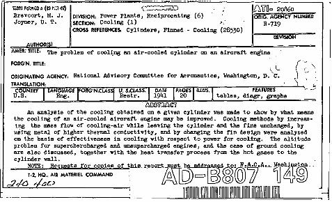
An analysis of the cooling obtained on a given cylinder vas made to Mev by vhat meansthe cooling of lllJ air-cooled aircraft engine may be improved. Cooling methods by increasing the mass flow of cooling-air vhi1e leaVing the cylinder and the fina unchanged, byusing metal of higher therme1 conductivity, and by changing the fin design vere analyzedon the basis of effectiveness in cooling with respect to pover for coo11ng. The altitudepl'oblem for superchercharged and unsupercharged engines, and the cese of ground coolingare also discussed, together with the heat trensfer process from the hot gases to thecylinder vall.
NCYl'E • Re ue sts 0
f:\:J I;
~~~~~.",.=-:~==","",-:-=::r-:.,....".....;-;"'....---=..--r.:=;::'T.......,r------.'<A.:;;;;;"----"---\.!;
~ ~~eA U. o.i ~l.i.r
~ ~ .~.\QL~ U.fCO
liIi >~ n 1')49 . - - - _
@ P d-1/7 , {71/3) ?/3/1@ -7f~gI0~ cyJ/nd~s
If:- fj,';-C/l.otyl-k/?a;neS~ /1/r CL}e> / oed
ffe<::A+ij&t/nG:KY"-
,F/ns
rherr>Ja~
~~v/Iu<I