Embed Size (px)
Citation preview
______________________________________________
1 Business Manager - NAFTA Dredging/ Water Treatments NAFTA, Ciba Specialty Chemicals Corporation, 765
Prairie Industrial Parkway, Mulberry, FL 33860, USA, T: 813-767-2829, Fax: 863-425-7112, Email:
2 Technical Manager / Water Treatments NAFTA, Ciba Specialty Chemicals Corporation, 2371 Wilroy Road,
Suffolk, VA 23434, USA, T: 757-538-5238, Fax: 757-538-5038, Email: [email protected];
3 Regulatory Toxicologist / Regulatory Services NAFTA, Ciba Specialty Chemicals Corporation, 540 White Plains
Road, Tarrytown, NY 10591, USA, T: 914-785-4007, Fax: 914-785-4147, Email: [email protected].
THE POSITIVE IMPACT OF POLYMERS ON SEDIMENT TREATMENT AND
HANDLING
Dewey W. Hunter1, Michael Heard, Ph.D.2, and Karin Baron, MSPH3
ABSTRACT
Several factors are taken into consideration when a sediment handling operation for a dredging project is designed
or implemented by a contractor. These factors – including operational efficiency, regulatory climate, project
economics, etc. - sometimes require adoption of solutions that go beyond the capability of conventional material
containment practices. One such solution is the use of polymers to improve the efficiency and cost-effectiveness
of an operation. Of significant importance is the selection of the proper chemistry to employ for a given substrate,
the appropriate equipment for chemical preparation and dosing, as well as working with competent vendors that
possess the know-how and experience with dredging applications, including the ability to work with the local and
regional regulatory agencies. This paper presents five examples where benefits from that sort of enhanced
solutions approach were realized. When polymers are considered in this way, they can go from improving the
quality of effluent produced, increasing the sedimentation and/or dewatering rate of dredged material, to positive
impacts on the overall profitability of a dredging project.
Keywords: Polyelectrolytes, coagulants/coagulation, flocculants/flocculation, polyacrylamide
INTRODUCTION
Polymers, which are more commonly known by water chemists as synthetic organic polyelectrolytes, have been
used in dredging in the United States for more than 30 years (Seagren 2003). However, their use over time has
been rather limited when compared to the total amount of sediments dredged annually. In contrast, polymers have
also been used to a much greater extent, and with a wider spectrum of applications, in the potable water and
wastewater markets since the 1950’s. The U.S. Army Corps of Engineers (USACE) has investigated, quite
extensively, the use of polymers with confined dredged material disposal projects. These are documented in
technical reports (Wang and Chen 1977), (Jones et al. 1978), (Schroeder 1983), (Wade 1988), (Bailey, et al. 2005),
in which polymer evaluations were conducted and testing protocols were used and/or established. Additionally,
the USACE has included information about the use of polymers and recommended testing methods within some of
their engineering manuals such as, Confined Disposal of Dredged Material (USACE 1987) and Design of Small
Water Systems (USACE 1999).
In spite of the body of information available, there still seems to be a need to fill some of the gaps with an
explanation of what polymers actually are, how they work, how to make the correct selection for a particular
substrate, and exactly how -and in what instances - one can benefit from their use. Perhaps, armed with this
information and shown some recent examples of where they have been used successfully, project owners and key
stakeholders may have a higher degree of comfort and confidence in considering the use of polymers in the early
planning stages.
Most polymer usage in dredging takes place within upland disposal operations or solids dewatering operations in
which enhanced solids/liquid separation and/or consolidation is desired. This occurs with freshwater or marine
substrates (either contaminated or non-contaminated), but can also take place in a myriad of commercial,
131

industrial, municipal, or public dredging applications, as well (Seagren 2003). Table 1 shows a partial list of these
types of projects and /or substrates in which polymer treatment can be considered.
Table 1. List of potential dredging substrates for polymer usage.
Metal Industry Wastes Petrochemical Wastes Power Plant (fly ash)
Textile Wastes Chemical Process Wastes Storm Water Run-Off
Construction (Erosion) High Water Table Excavation Paper Mill Wastes
River Silt, Muck, & Clay Lake Silt, Muck, & Clay Marina/Dock Silt, Muck, & Clay
Inland Canals Silt, Muck, & Clay Lock/Dam Silt, Muck & Clay Aggregate Washing
Acid Mine Drainage Coal Washing Water Supply Reservoirs
Mineral Tailings Municipal Wastewater Lagoons Cooling Water Ponds
Cannery Wastes Leather and Tanning Wastes Sugar Processing Wastes
Atomic Wastes Contaminated Sediments Combined Sewage Outfall
From the list shown in Table 1, the following is a partial list of some of the characteristics those substrates exhibit,
either individually or in combination, which make them amenable to polymer treatment:
Fine-grained sediments (i.e., organic and inorganic silts and clays, fine sand)
Highly organic soils or substrates
Grain size below No. 200 mesh (0.075 mm or 75 microns)
High surface area-to-mass ratio of particles
GENERAL DESCRIPTION OF POLYMERS
Polymers, in the sense we will be dealing with, are synthetic, in that they are not naturally occurring, but rather are
man-made substances based primarily on water soluble polymer chemistry. They are organic because they are
composed of carbon-based molecules that link together to form long chained compounds (i.e., macromolecules) of
repeating single monomer units. The length of the chain formed for a particular polymer is an indication of its
relative molecular weight, typically shown in units of 106 amu (atomic mass units), or on a relative scale of low-
high. In other words, the longer the chain, the higher its relative molecular weight. The chains are reacted with
various types of charge monomers, which give the chain either a predominance of positive charge, negative
charge, or a neutral charge. The units of measure used for charge density is meq/g (milli-equivalents per gram), or
it can just be shown on a relative scale of 0-100%. These types of polymers are referred to as polyelectrolytes
because when they are dissolved in water, they exhibit electrolytic charge based on the charge monomers they
were reacted with during the manufacturing (or polymerization) process. Figure 1 illustrates how polymers can
range in both molecular weight and in charge density by the information just described.
Figure 1. Chemical characteristics of polymers.
Charge Density
Molecular Weight
Medium
Low
High
0
+50% -50% -100% Nonionic
Anionic Cationic
I
Inorganic Coagulants (Lime, Alum, Iron Salts)
Organic Coagulants (PolyDMDAAC, Polyamine)
Flocculants (Polyacrylamide based Copolymers)
Flocculants (Polyacrylamide based Copolymers)
Dispersants (Polyacrylic Acid)
+100%
132
Coagulants and Coagulation
Due to their high surface area-to-mass ratio, fine-grained (i.e., below No. 200 mesh or approx. <75 microns)
sediments and soils in water have the tendency to attract and display electrical charge properties. This means that
most of those particles will have a similar charge and repel one another, as well as resist the natural influences of
gravity to settle. In other words, they can form a stable colloidal suspension. Water treatment coagulants are
chemicals that induce instability and agglomeration into a water based colloidal suspension that would otherwise
only settle out over a long period of time. Hence, the primary function of the coagulant is to destabilize the
suspension by neutralizing the surface charge upon the suspended particle, thereby, removing the electrostatic
repulsion between the particles and allowing the particles to get close enough for forces of attraction to act and
agglomerate the material. Inorganic coagulants employ metal cations (positive charge) for their effectiveness and,
therefore, salts of iron and aluminum are commonly used. These may be applied as simple salt solutions of
materials such as ferric chloride, ferric sulphate, aluminum sulphate or aluminum chloride, or the more complex
poly-aluminum ion solutions, such as polyaluminum chloride and aluminum chlorohydrate.
Due to difficulties experienced with product handling issues, pH limitations, and additional solids generation
inherent with the use of inorganic coagulants, synthetic organic coagulants were developed and became a viable
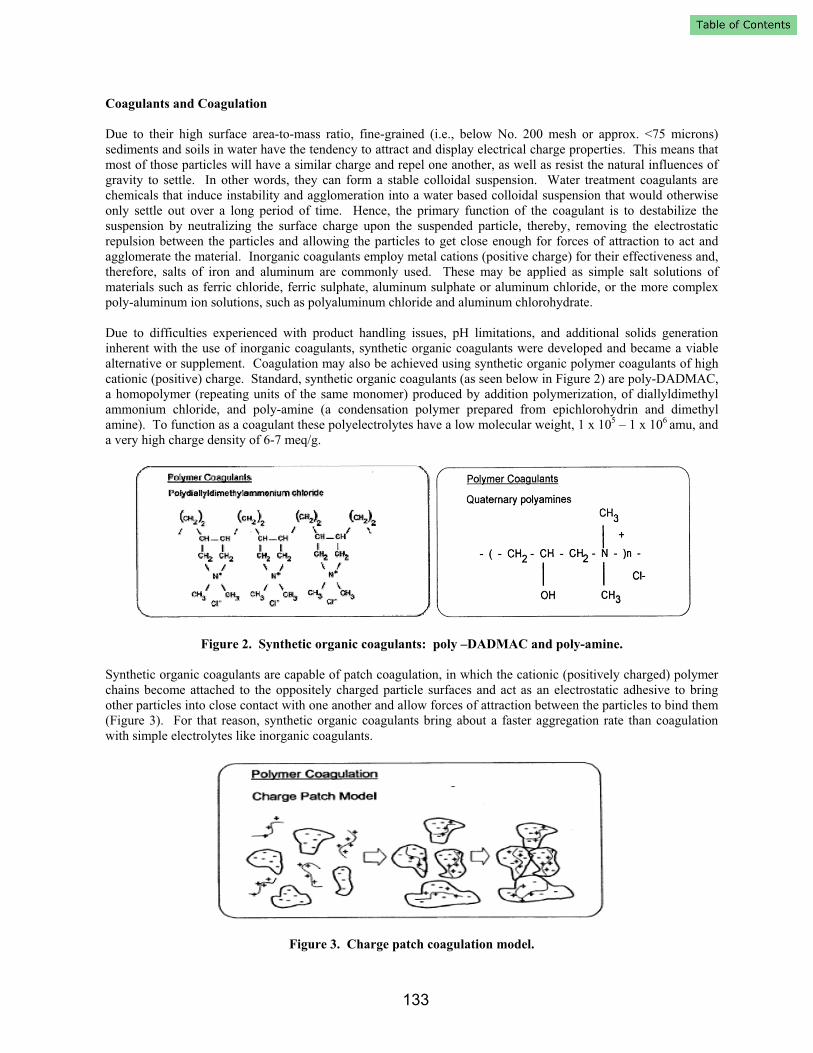
alternative or supplement. Coagulation may also be achieved using synthetic organic polymer coagulants of high
cationic (positive) charge. Standard, synthetic organic coagulants (as seen below in Figure 2) are poly-DADMAC,
a homopolymer (repeating units of the same monomer) produced by addition polymerization, of diallyldimethyl
ammonium chloride, and poly-amine (a condensation polymer prepared from epichlorohydrin and dimethyl
amine). To function as a coagulant these polyelectrolytes have a low molecular weight, 1 x 10⁵ – 1 x 10⁶ amu, and
a very high charge density of 6-7 meq/g.
Figure 2. Synthetic organic coagulants: poly –DADMAC and poly-amine.
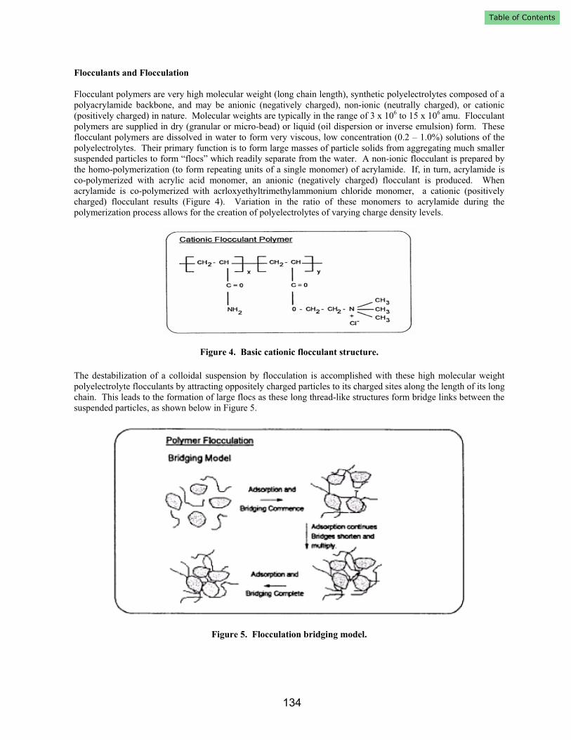
Synthetic organic coagulants are capable of patch coagulation, in which the cationic (positively charged) polymer
chains become attached to the oppositely charged particle surfaces and act as an electrostatic adhesive to bring
other particles into close contact with one another and allow forces of attraction between the particles to bind them
(Figure 3). For that reason, synthetic organic coagulants bring about a faster aggregation rate than coagulation
with simple electrolytes like inorganic coagulants.
Figure 3. Charge patch coagulation model.
133
Flocculants and Flocculation
Flocculant polymers are very high molecular weight (long chain length), synthetic polyelectrolytes composed of a
polyacrylamide backbone, and may be anionic (negatively charged), non-ionic (neutrally charged), or cationic
(positively charged) in nature. Molecular weights are typically in the range of 3 x 10⁶ to 15 x 106 amu. Flocculant
polymers are supplied in dry (granular or micro-bead) or liquid (oil dispersion or inverse emulsion) form. These
flocculant polymers are dissolved in water to form very viscous, low concentration (0.2 – 1.0%) solutions of the
polyelectrolytes. Their primary function is to form large masses of particle solids from aggregating much smaller
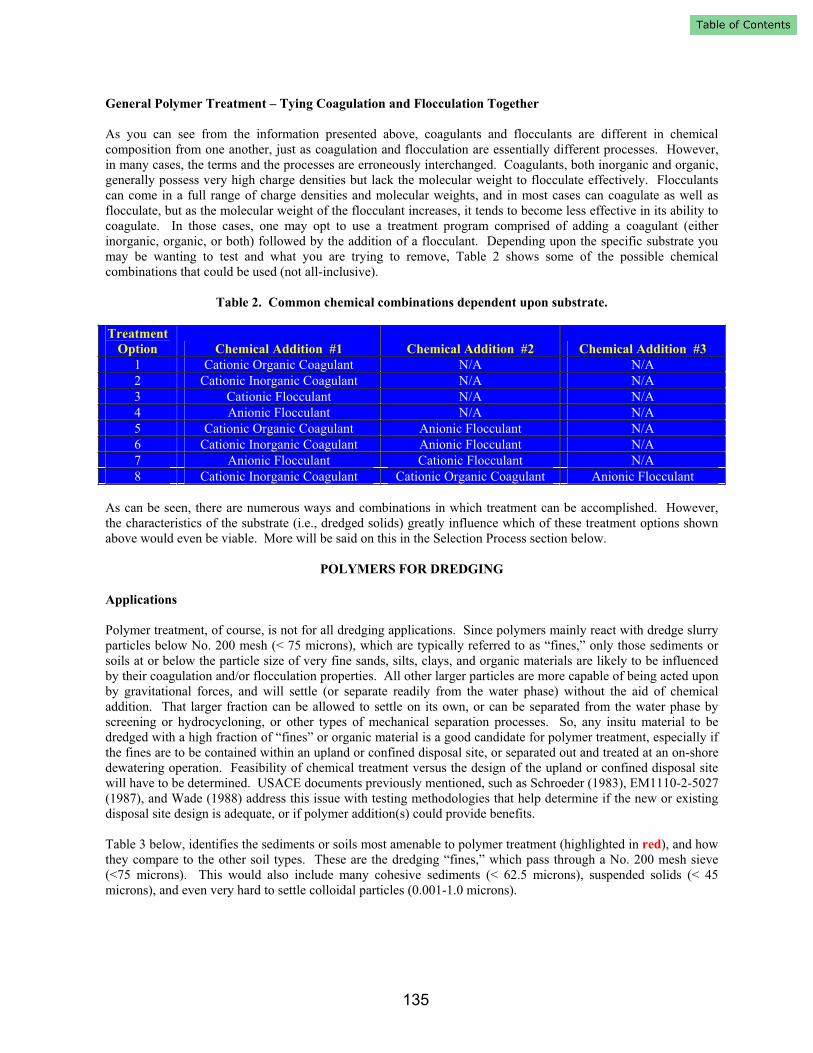
suspended particles to form “flocs” which readily separate from the water. A non-ionic flocculant is prepared by
the homo-polymerization (to form repeating units of a single monomer) of acrylamide. If, in turn, acrylamide is
co-polymerized with acrylic acid monomer, an anionic (negatively charged) flocculant is produced. When
acrylamide is co-polymerized with acrloxyethyltrimethylammonium chloride monomer, a cationic (positively
charged) flocculant results (Figure 4). Variation in the ratio of these monomers to acrylamide during the
polymerization process allows for the creation of polyelectrolytes of varying charge density levels.
Figure 4. Basic cationic flocculant structure.
The destabilization of a colloidal suspension by flocculation is accomplished with these high molecular weight
polyelectrolyte flocculants by attracting oppositely charged particles to its charged sites along the length of its long
chain. This leads to the formation of large flocs as these long thread-like structures form bridge links between the
suspended particles, as shown below in Figure 5.
Figure 5. Flocculation bridging model.
134
General Polymer Treatment – Tying Coagulation and Flocculation Together
As you can see from the information presented above, coagulants and flocculants are different in chemical
composition from one another, just as coagulation and flocculation are essentially different processes. However,
in many cases, the terms and the processes are erroneously interchanged. Coagulants, both inorganic and organic,
generally possess very high charge densities but lack the molecular weight to flocculate effectively. Flocculants
can come in a full range of charge densities and molecular weights, and in most cases can coagulate as well as
flocculate, but as the molecular weight of the flocculant increases, it tends to become less effective in its ability to
coagulate. In those cases, one may opt to use a treatment program comprised of adding a coagulant (either
inorganic, organic, or both) followed by the addition of a flocculant. Depending upon the specific substrate you
may be wanting to test and what you are trying to remove, Table 2 shows some of the possible chemical
combinations that could be used (not all-inclusive).
Table 2. Common chemical combinations dependent upon substrate.
Treatment
Option Chemical Addition #1 Chemical Addition #2 Chemical Addition #3
1 Cationic Organic Coagulant N/A N/A
2 Cationic Inorganic Coagulant N/A N/A
3 Cationic Flocculant N/A N/A
4 Anionic Flocculant N/A N/A
5 Cationic Organic Coagulant Anionic Flocculant N/A
6 Cationic Inorganic Coagulant Anionic Flocculant N/A
7 Anionic Flocculant Cationic Flocculant N/A
8 Cationic Inorganic Coagulant Cationic Organic Coagulant Anionic Flocculant
As can be seen, there are numerous ways and combinations in which treatment can be accomplished. However,
the characteristics of the substrate (i.e., dredged solids) greatly influence which of these treatment options shown
above would even be viable. More will be said on this in the Selection Process section below.
POLYMERS FOR DREDGING
Applications
Polymer treatment, of course, is not for all dredging applications. Since polymers mainly react with dredge slurry
particles below No. 200 mesh (< 75 microns), which are typically referred to as “fines,” only those sediments or
soils at or below the particle size of very fine sands, silts, clays, and organic materials are likely to be influenced
by their coagulation and/or flocculation properties. All other larger particles are more capable of being acted upon
by gravitational forces, and will settle (or separate readily from the water phase) without the aid of chemical
addition. That larger fraction can be allowed to settle on its own, or can be separated from the water phase by
screening or hydrocycloning, or other types of mechanical separation processes. So, any insitu material to be
dredged with a high fraction of “fines” or organic material is a good candidate for polymer treatment, especially if
the fines are to be contained within an upland or confined disposal site, or separated out and treated at an on-shore
dewatering operation. Feasibility of chemical treatment versus the design of the upland or confined disposal site
will have to be determined. USACE documents previously mentioned, such as Schroeder (1983), EM1110-2-5027
(1987), and Wade (1988) address this issue with testing methodologies that help determine if the new or existing
disposal site design is adequate, or if polymer addition(s) could provide benefits.
Table 3 below, identifies the sediments or soils most amenable to polymer treatment (highlighted in red), and how
they compare to the other soil types. These are the dredging “fines,” which pass through a No. 200 mesh sieve
(<75 microns). This would also include many cohesive sediments (< 62.5 microns), suspended solids (< 45
microns), and even very hard to settle colloidal particles (0.001-1.0 microns).
135
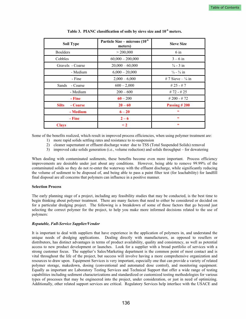
Table 3. PIANC classification of soils by sieve size and 10-6
meters.
Soil TypeParticle Size – microns (10
-6
meters)Sieve Size
Boulders > 200,000 6 in
Cobbles 60,000 – 200,000 3 – 6 in
Gravels - Coarse 20,000 – 60,000 ¾ - 3 in
- Medium 6,000 – 20,000 ¼ - ¾ in
- Fine 2,000 – 6,000 # 7 Sieve – ¼ in
Sands - Coarse 600 – 2,000 # 25 - # 7
- Medium 200 – 600 # 72 - # 25
- Fine 60 – 200 # 200 - # 72
Silts - Coarse 20 – 60 Passing # 200
- Medium 6 – 20 “
- Fine 2 – 6 “
Clays < 2 “
Some of the benefits realized, which result in improved process efficiencies, when using polymer treatment are:
1) more rapid solids settling rates and resistance to re-suspension
2) cleaner supernatant or effluent discharge water due to TSS (Total Suspended Solids) removal
3) improved cake solids generation (i.e., volume reduction) and solids throughput – for dewatering
When dealing with contaminated sediments, these benefits become even more important. Process efficiency
improvements are desirable under just about any conditions. However, being able to remove 99.99% of the
contaminated solids so they do not re-enter the waterway with the effluent discharge, while significantly reducing
the volume of sediment to be disposed of, and being able to pass a paint filter test (for leachability) for landfill
final disposal are all concerns that polymers can influence in a positive manner.
Selection Process
The early planning stage of a project, including any feasibility studies that may be conducted, is the best time to
begin thinking about polymer treatment. There are many factors that need to either be considered or decided on
for a particular dredging project. The following is a breakdown of some of those factors that go beyond just
selecting the correct polymer for the project, to help you make more informed decisions related to the use of
polymers:
Reputable, Full-Service Supplier/Vendor
It is important to deal with suppliers that have experience in the application of polymers in, and understand the
unique needs of dredging applications. Dealing directly with manufacturers, as opposed to resellers or
distributors, has distinct advantages in terms of product availability, quality and consistency, as well as potential
access to new product development or launches. Look for a supplier with a broad portfolio of services with a
strong customer focus. The supplier’s Sales/Marketing department is the common point of most contact and is
vital throughout the life of the project, but success will involve having a more comprehensive organization and
resources to draw upon. Equipment Services is very important, especially one that can provide a variety of related
polymer storage, makedown, dosing (conventional and automated dose control), and monitoring equipment.
Equally as important are Laboratory Testing Services and Technical Support that offer a wide range of testing
capabilities including sediment characterizations and standardized or customized testing methodologies for various
types of processes that may be engineered into the project, under consideration, or just in need of optimizing.
Additionally, other related support services are critical. Regulatory Services help interface with the USACE and
136
with various local and regional water districts, environmental agencies, and advocacy groups. For routine order
placement and to help deal with any unexpected disruptions in product supply or quality, Customer Services can
play a vital role in seeking out root cause, resolving the situations, and preventing them from reoccurrence. Last,
but certainly not least, is the necessity for Field Support that entails work that may need to be performed before,
during, and after the project has been completed. A low price from a local supplier for just polymer, alone, is
rarely a good ingredient for a successful project. It is advisable to obtain all pricing up front, rather than allowing
for subsequent, unaccounted for charges to mount up as the project gets under way. Due to polymer pricing being
tied to the price of oil and to global shortages of related raw materials (used in polymer manufacture) that may
exist as a result, longer term project contracts (> 1 year) should include some provision for price escalation or
adjustment based on the Chemical Price Index.
Project and Treatment Objectives
Know early on, based on the type(s) of sediments likely to be encountered, whether polymer(s) should or could be
considered. As previously stated, that would depend, in large part, upon the concentration of fine-grained material
expected from any insitu analyses conducted, and upon whether or not the sediments are considered contaminated
or not. Timing and duration of the project will also be important factors to consider. These, of course, influence
the engineering of the disposal area or the treatment process, but from a polymer perspective, could affect the flow
rates and necessary equipment sizing, as well as seasonal considerations (e.g., shelter, winterization, down-time,
etc…). Effluent discharge limits for a particular project may also be a reason to consider the use of polymer
treatment, and/or if dewatering of the solids is to be done. If the dewatered materials are to be hauled away any
kind of distance, and depending upon how the hauling contract or the contract with the final disposal site (e.g.,
landfill) is structured, cake dry solids content may need to be maximized (usually by the use of polymers) in order
to maximize the tonnage of actual dredged solids being loaded out per truckload, or to improve acceptability of the
consolidated sludge cake at the landfill.
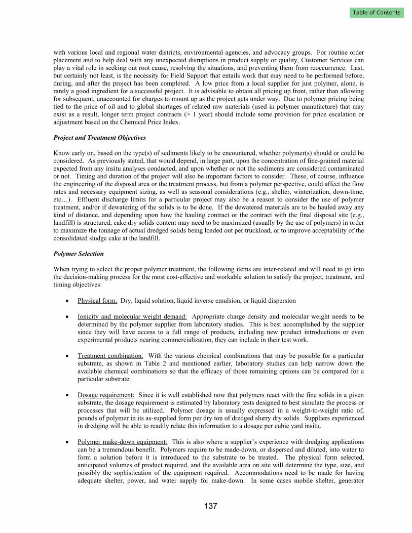
Polymer Selection
When trying to select the proper polymer treatment, the following items are inter-related and will need to go into
the decision-making process for the most cost-effective and workable solution to satisfy the project, treatment, and
timing objectives:
Physical form: Dry, liquid solution, liquid inverse emulsion, or liquid dispersion
Ionicity and molecular weight demand: Appropriate charge density and molecular weight needs to be
determined by the polymer supplier from laboratory studies. This is best accomplished by the supplier
since they will have access to a full range of products, including new product introductions or even
experimental products nearing commercialization, they can include in their test work.
Treatment combination: With the various chemical combinations that may be possible for a particular
substrate, as shown in Table 2 and mentioned earlier, laboratory studies can help narrow down the
available chemical combinations so that the efficacy of those remaining options can be compared for a
particular substrate.
Dosage requirement: Since it is well established now that polymers react with the fine solids in a given
substrate, the dosage requirement is estimated by laboratory tests designed to best simulate the process or
processes that will be utilized. Polymer dosage is usually expressed in a weight-to-weight ratio of,
pounds of polymer in its as-supplied form per dry ton of dredged slurry dry solids. Suppliers experienced
in dredging will be able to readily relate this information to a dosage per cubic yard insitu.
Polymer make-down equipment: This is also where a supplier’s experience with dredging applications
can be a tremendous benefit. Polymers require to be made-down, or dispersed and diluted, into water to
form a solution before it is introduced to the substrate to be treated. The physical form selected,
anticipated volumes of product required, and the available area on site will determine the type, size, and
possibly the sophistication of the equipment required. Accommodations need to be made for having
adequate shelter, power, and water supply for make-down. In some cases mobile shelter, generator
137
power, and resident water may have to be considered. The polymer supplier needs to have the necessary
resources to assess the equipment needs of the project, perform a site audit (if possible), and be able to
present viable recommendations for equipment as a part of their overall proposal package.
Storage, Handling, and Safety: The physical form of polymer selected and the anticipated volumes of
product required will help to dictate the type of packaging and/or on-site storage that may be required.
Check with your supplier to see what packaging options they may provide. Dry polymers can be
packaged in small bags (~25 kg (~ 55 lb)), various tay bags (~ 544 - 907 kg (~ 1,200 – 2,000 lb)),
stainless steel returnable tote bins (~907 kg (~ 2,000 lb)), or it can even be supplied in bulk (approx.
18,144 kg (40,000 lb)) into a silo system, if necessary. Liquids are typically supplied in drums (~188 –
208 liters (~50-55 gallons)), tote bins (~946 liters (~250 gallons)), or in bulk (~18,925 liters (~5,000
gallons)). Information should be provided from your supplier and on the MSDS regarding specific
storage, handling, and safety guidelines.
Environmental: The physical form of polymer (i.e., dry polymer, water based liquid coagulant, oil based
inverse emulsion, or oil based liquid dispersion) and the Ionicity (charge density relative to whether it is
anionic, cationic, or nonionic) will help determine its estimated ecotoxicity, and a specific product
decision could be made based on that information.
Examples and Benefits
The following are examples of dredging projects that have taken place over the last five years (2002 – present), in
which upland disposal or treatment of sediments took place, all involving the use of polymer. They are also
examples in which polymers played a significant role in the accomplishment of the overall project and treatment
objectives, as well as examples of how the Selection Process detailed above can be instrumental in improving your
chances for success. Five different projects are shown below in Table 4. Three of the five projects had previously
failed attempts at treatment. However, when the Selection Process was introduced and followed, coupled with the
appointment of a new general contractor as well, a turn-around in results occurred. In all five of these cases, the
projects ran well from the first day of treatment until completion, which resulted in minimal down-time, and
positively influenced dredge production. Therefore, the projects experienced little to no costs associated with loss
of dredging production due to poor or improper polymer treatment. Four of the five projects utilized automated
polymer dosage control to help adjust for fluctuations that are usually experienced with incoming slurry
concentration. This allowed for the minimization of polymer dosages, which, in turn, minimized residual polymer
from being discharged back into the waterway.
Table 4. Successful Dredging Projects Utilizing Polymer
Olmsted
Locks &Dam Murrells Inlet Conner Creek Fox River Miami River
Year 2002 2003 2003-2004 2005- 2005-
Location Olmsted, IL
Murrells Inlet,
SC Detroit, MI Neenah, WI Miami, FL
Sediment
Type
Non-
Contaminated
Non-
Contaminated Contaminated Contaminated Contaminated
Dredge Type Hydraulic Hydraulic Hydraulic Hydraulic
Mechanical Back
Hoe
Process 3-Tiered
Containment
Area
Screening;
RDS®
Thickening; Belt
Press
Dewatering
Screening;
Geotube®
Dewatering
Gravity
Thickening;
Geotube®
Dewatering
MSWP®; 3 Stage
Screening/Separation;
Gravity Thickening;
Belt Press
Dewatering
Polymer Type
and Form Cationic Liquid
Coagulant
Anionic Liquid
Flocculant +
Cationic Liquid
Flocculant
Cationic Dry
Flocculant
Cationic Dry
Flocculant;
Cationic Dry
Flocculant
Cationic Liquid
Emulsion; Cationic
Liquid Dispersion
138
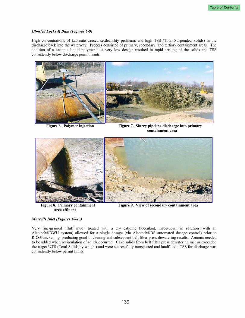
Olmsted Locks & Dam (Figures 6-9)
High concentrations of kaolinite caused settleability problems and high TSS (Total Suspended Solids) in the
discharge back into the waterway. Process consisted of primary, secondary, and tertiary containment areas. The
addition of a cationic liquid polymer at a very low dosage resulted in rapid settling of the solids and TSS
consistently below discharge permit limits.
Figure 6. Polymer injection Figure 7. Slurry pipeline discharge into primary
containment area
Figure 8. Primary containment Figure 9. View of secondary containment area
area effluent
Murrells Inlet (Figures 10-13)
Very fine-grained “fluff mud” treated with a dry cationic flocculant, made-down in solution (with an
Alcotech®DWU system) allowed for a single dosage (via Alcotech®DS automated dosage control) prior to
RDS®thickening, producing good thickening and subsequent belt filter press dewatering results. Anionic needed
to be added when recirculation of solids occurred. Cake solids from belt filter press dewatering met or exceeded
the target %TS (Total Solids by weight) and were successfully transported and landfilled. TSS for discharge was
consistently below permit limits.
139

Figure 10. Polymer injection prior to RDS® Figure 11. Thickened solids coming off the RDS®
thickeners thickener
Figure 12. Cake solids coming off 1 of 2 Figure 13. Effluent discharge returning back
belt filter presses to the marina
Conner Creek (Figures 14-17)
PCB and mercury contaminated sediment was treated with made-down solution of a cationic dry flocculant (with
an Alcotech®DWU system) prior to entering Geotubes® for dewatering. Automated dose control (Alcotech®DS)
was set and never changed for the duration of the project. Cake solids generated were at or above %TS target and
acceptable to the landfill. Discharge was consistently below discharge permit limits on TSS, PCBs, and mercury.
Polymer injection on dredge pipeline Polymer make-down system for dry polymer
Figure 14. Polymer injection into pipeline Figure 15. Alcotech®DWU dry polymer
make-down system
140

Figure 16. Geotubes being filled with Figure 17. Geotube® weep being returned back
flocculated solids and draining to the waterway
Fox River (Figures 18-21)
For the 2005 dredging season, PCB contaminated sediment was treated with made-down solution of a cationic dry
flocculant (with an Alcotech®DWU system) prior to gravity thickening (2006), followed by Geotube®
dewatering. Automated dose control (Alcotech®DS) worked well when used and when solids were “in-range” for
the system to function. Cake solids ranged from slightly below to above the %TS target when automated dosage
control was used. Discharge was consistently below permit limits on TSS and PCBs.
Figure 18. Polymer addition point into Figure 19. Alcotech®DWU dry
2 slurry pipelines polymer make-down system
Figure 20. Alcotech®DS polymer Figure 21. Geotubes filled with flocculated solids and draining
dosage control system
141
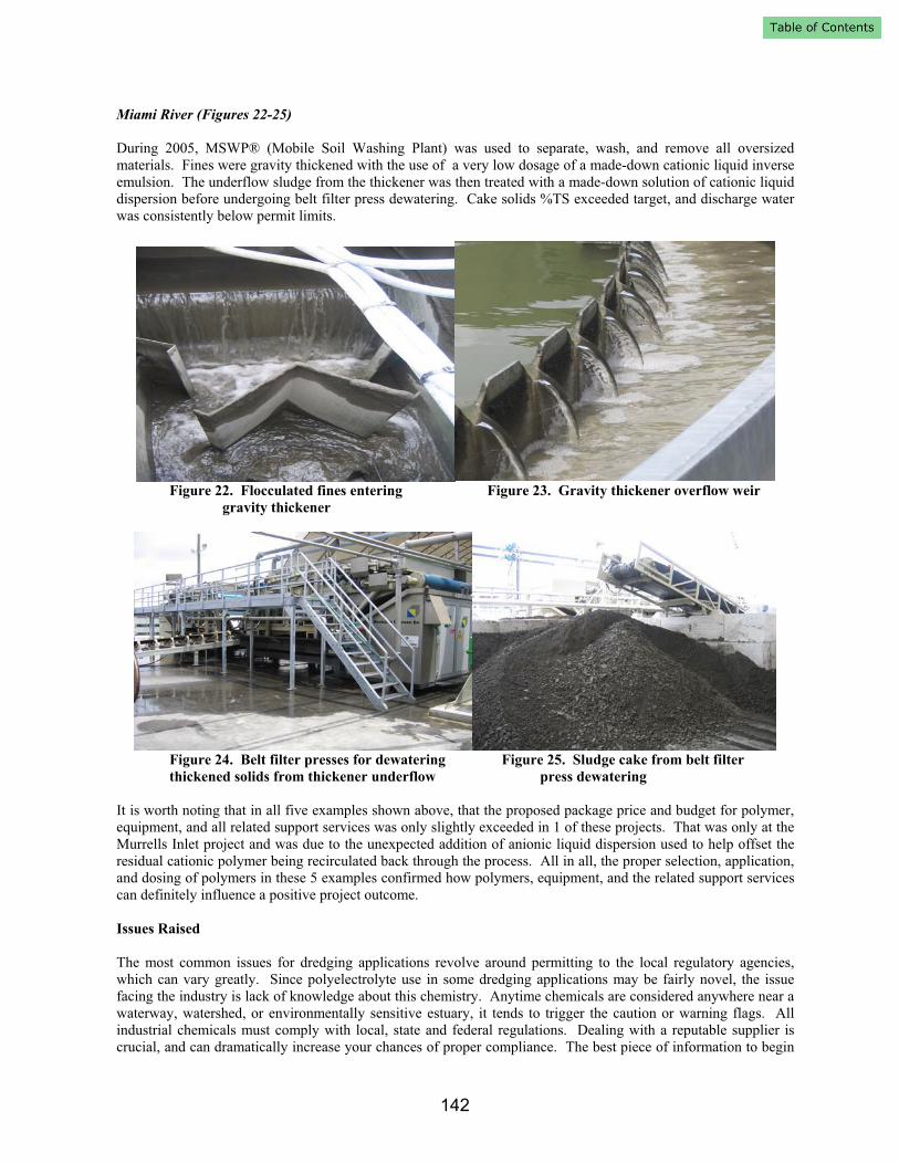
Miami River (Figures 22-25)
During 2005, MSWP® (Mobile Soil Washing Plant) was used to separate, wash, and remove all oversized
materials. Fines were gravity thickened with the use of a very low dosage of a made-down cationic liquid inverse
emulsion. The underflow sludge from the thickener was then treated with a made-down solution of cationic liquid
dispersion before undergoing belt filter press dewatering. Cake solids %TS exceeded target, and discharge water
was consistently below permit limits.
Figure 22. Flocculated fines entering Figure 23. Gravity thickener overflow weir
gravity thickener
Figure 24. Belt filter presses for dewatering Figure 25. Sludge cake from belt filter
thickened solids from thickener underflow press dewatering
It is worth noting that in all five examples shown above, that the proposed package price and budget for polymer,
equipment, and all related support services was only slightly exceeded in 1 of these projects. That was only at the
Murrells Inlet project and was due to the unexpected addition of anionic liquid dispersion used to help offset the
residual cationic polymer being recirculated back through the process. All in all, the proper selection, application,
and dosing of polymers in these 5 examples confirmed how polymers, equipment, and the related support services
can definitely influence a positive project outcome.
Issues Raised
The most common issues for dredging applications revolve around permitting to the local regulatory agencies,
which can vary greatly. Since polyelectrolyte use in some dredging applications may be fairly novel, the issue
facing the industry is lack of knowledge about this chemistry. Anytime chemicals are considered anywhere near a
waterway, watershed, or environmentally sensitive estuary, it tends to trigger the caution or warning flags. All
industrial chemicals must comply with local, state and federal regulations. Dealing with a reputable supplier is
crucial, and can dramatically increase your chances of proper compliance. The best piece of information to begin
142
with is the supplier-provided Material Safety Data Sheet or MSDS (sometimes referred to as SDS or Safety Data
Sheet). A good MSDS will contain a tremendous amount of vital information.
Health Concerns
The MSDS identifies any OSHA (Occupational Safety and Health Administration) workplace health or physical
hazards associated with each specific polymer. Some individuals may experience irritation to their eyes, skin, or
respiratory system when handling certain types of polymers, and proper exposure controls and PPE (personal
protective equipment), as spelled out in the MSDS, should be followed. The main physical hazards associated
with polymers are the slip hazard potential when any polymer becomes wet, and a dust explosion potential for dry
polymers. Avoiding and cleaning up polymer spills right away, in addition to following the guidelines within the
product-specific MSDS will ensure safe and effective use of that particular polymer.
Environmental Concerns
Toxicity and Ecotoxicity information is usually documented in later sections of the MSDS depending on the
formatting. In those sections acute (short term) and chronic (longer term) toxicity and ecotoxicity information is
usually detailed. For dredging, the concern for customers and regulating agencies is the direct impact to the
environment, i.e., ecotoxicity. Ecotoxicity values are typically reported in terms of LC50 or EC50 which is the
lethal concentration (LC) or effective concentration (EC) at which 50% of the test subjects died or were adversely
affected by the test substance. These tests are conducted on various species. The most common are vertebrate fish
species from freshwater and/or marine water environments and invertebrate species from freshwater or marine
environments. There are many methods and time frames utilized for executing these types of studies. The most
common time frames range from 48 – 96 hours in duration for short term (acute) and 7 – 21 days and beyond for
longer term (chronic) studies. The choice of test species is critical for certain governing bodies as well as the
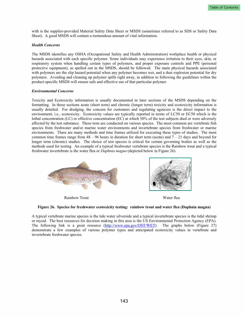
methods used for testing. An example of a typical freshwater vertebrate species is the Rainbow trout and a typical
freshwater invertebrate is the water flea or Daphnia magna (depicted below in Figure 26).
Rainbow Trout Water flea
Figure 26. Species for freshwater ecotoxicity testing: rainbow trout and water flea (Daphnia magna)
A typical vertebrate marine species is the tide water silverside and a typical invertebrate species is the tidal shrimp
or mysid. The best resources for decision making in this area is the US Environmental Protection Agency (EPA).
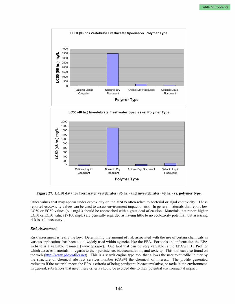
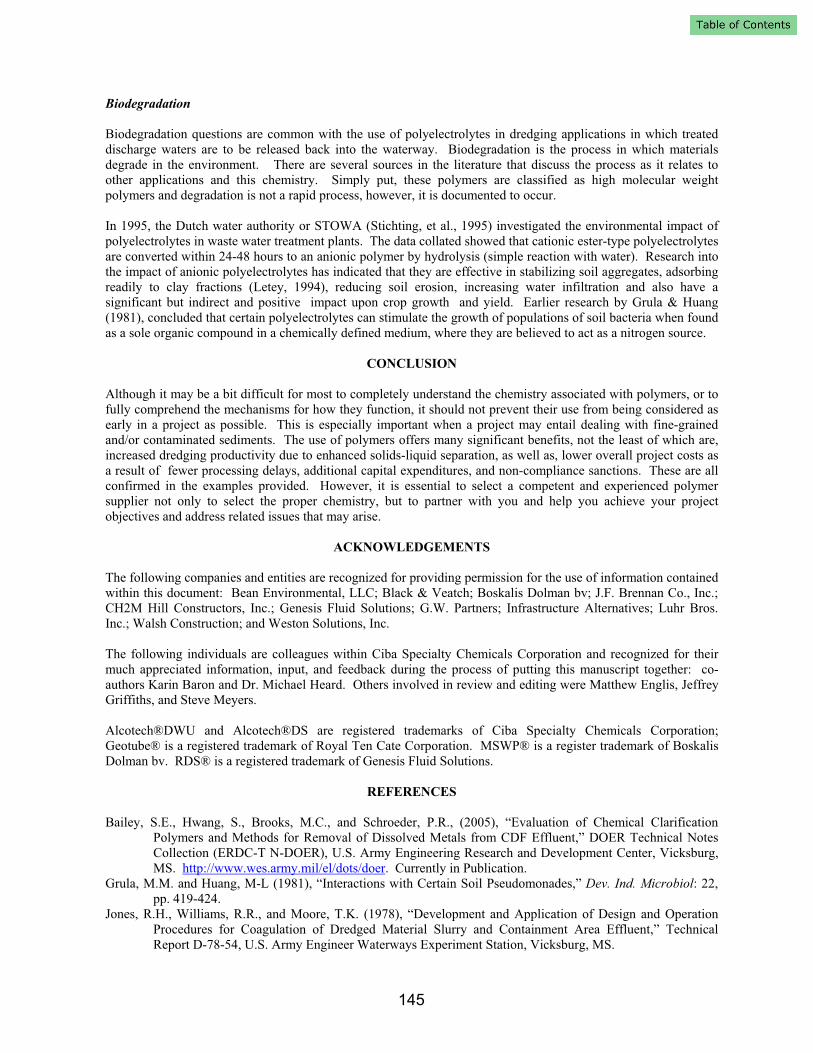
The following link is a great resource (http://www.epa.gov/OST/WET). The graphs below (Figure 27)
demonstrate a few examples of various polymer types and anticipated ecotoxicity values in vertebrate and
invertebrate freshwater species.
143
LC50 (96 hr.) Vertebrate Freshwater Species vs. Polymer Type
0
500
1000
1500
2000
2500
3000
3500
4000
Cationic Liquid
Coagulant
Nonionic Dry
Flocculant
Anionic Dry Flocculant Cationic Liquid
Flocculant
Polymer Type
LC
50 (
96 h
r.)
mg
/L
LC50 (48 hr.) Invertebrate Freshwater Species vs. Polymer Type
0
200
400
600
800
1000
1200
1400
1600
1800
2000
Cationic Liquid
Coagulant
Nonionic Dry
Flocculant
Anionic Dry Flocculant Cationic Liquid
Flocculant
Polymer Type
LC
50 (
48 h
r.)
mg
/L
Figure 27. LC50 data for freshwater vertebrates (96 hr.) and invertebrates (48 hr.) vs. polymer type.
Other values that may appear under ecotoxicity on the MSDS often relate to bacterial or algal ecotoxicity. These
reported ecotoxicity values can be used to assess environment impact or risk. In general materials that report low
LC50 or EC50 values (< 1 mg/L) should be approached with a great deal of caution. Materials that report higher
LC50 or EC50 values (>100 mg/L) are generally regarded as having little to no ecotoxicity potential, but assessing
risk is still necessary.
Risk Assessment
Risk assessment is really the key. Determining the amount of risk associated with the use of certain chemicals in
various applications has been a tool widely used within agencies like the EPA. For tools and information the EPA
website is a valuable resource (www.epa.gov). One tool that can be very valuable is the EPA’s PBT Profiler
which assesses materials in regards to their persistence, bioaccumulation, and toxicity. This tool can also found on
the web (http://www.pbtprofiler.net). This is a search engine type tool that allows the user to “profile” either by
the structure of chemical abstract services number (CAS#) the chemical of interest. The profile generated
estimates if the material meets the EPA’s criteria of being persistent, bioaccumulative, or toxic in the environment.
In general, substances that meet these criteria should be avoided due to their potential environmental impact.
144
Biodegradation
Biodegradation questions are common with the use of polyelectrolytes in dredging applications in which treated
discharge waters are to be released back into the waterway. Biodegradation is the process in which materials
degrade in the environment. There are several sources in the literature that discuss the process as it relates to
other applications and this chemistry. Simply put, these polymers are classified as high molecular weight
polymers and degradation is not a rapid process, however, it is documented to occur.
In 1995, the Dutch water authority or STOWA (Stichting, et al., 1995) investigated the environmental impact of
polyelectrolytes in waste water treatment plants. The data collated showed that cationic ester-type polyelectrolytes
are converted within 24-48 hours to an anionic polymer by hydrolysis (simple reaction with water). Research into
the impact of anionic polyelectrolytes has indicated that they are effective in stabilizing soil aggregates, adsorbing
readily to clay fractions (Letey, 1994), reducing soil erosion, increasing water infiltration and also have a
significant but indirect and positive impact upon crop growth and yield. Earlier research by Grula & Huang
(1981), concluded that certain polyelectrolytes can stimulate the growth of populations of soil bacteria when found
as a sole organic compound in a chemically defined medium, where they are believed to act as a nitrogen source.
CONCLUSION
Although it may be a bit difficult for most to completely understand the chemistry associated with polymers, or to
fully comprehend the mechanisms for how they function, it should not prevent their use from being considered as
early in a project as possible. This is especially important when a project may entail dealing with fine-grained
and/or contaminated sediments. The use of polymers offers many significant benefits, not the least of which are,
increased dredging productivity due to enhanced solids-liquid separation, as well as, lower overall project costs as
a result of fewer processing delays, additional capital expenditures, and non-compliance sanctions. These are all
confirmed in the examples provided. However, it is essential to select a competent and experienced polymer
supplier not only to select the proper chemistry, but to partner with you and help you achieve your project
objectives and address related issues that may arise.
ACKNOWLEDGEMENTS
The following companies and entities are recognized for providing permission for the use of information contained
within this document: Bean Environmental, LLC; Black & Veatch; Boskalis Dolman bv; J.F. Brennan Co., Inc.;
CH2M Hill Constructors, Inc.; Genesis Fluid Solutions; G.W. Partners; Infrastructure Alternatives; Luhr Bros.
Inc.; Walsh Construction; and Weston Solutions, Inc.
The following individuals are colleagues within Ciba Specialty Chemicals Corporation and recognized for their
much appreciated information, input, and feedback during the process of putting this manuscript together: co-
authors Karin Baron and Dr. Michael Heard. Others involved in review and editing were Matthew Englis, Jeffrey
Griffiths, and Steve Meyers.
Alcotech®DWU and Alcotech®DS are registered trademarks of Ciba Specialty Chemicals Corporation;
Geotube® is a registered trademark of Royal Ten Cate Corporation. MSWP® is a register trademark of Boskalis
Dolman bv. RDS® is a registered trademark of Genesis Fluid Solutions.
REFERENCES
Bailey, S.E., Hwang, S., Brooks, M.C., and Schroeder, P.R., (2005), “Evaluation of Chemical Clarification
Polymers and Methods for Removal of Dissolved Metals from CDF Effluent,” DOER Technical Notes
Collection (ERDC-T N-DOER), U.S. Army Engineering Research and Development Center, Vicksburg,
MS. http://www.wes.army.mil/el/dots/doer. Currently in Publication.
Grula, M.M. and Huang, M-L (1981), “Interactions with Certain Soil Pseudomonades,” Dev. Ind. Microbiol: 22,
pp. 419-424.
Jones, R.H., Williams, R.R., and Moore, T.K. (1978), “Development and Application of Design and Operation
Procedures for Coagulation of Dredged Material Slurry and Containment Area Effluent,” Technical
Report D-78-54, U.S. Army Engineer Waterways Experiment Station, Vicksburg, MS.
145
Letey, J., (1994), “Adsorption and Desorption of Polymers on Soil,” Soil Science 158(4): pp. 244-248.
Seagren, E.H., (2003), “Flocculation Enhancement Technologies for the Dredging Contractor: Guidelines for the
Selection of a Polymer Supplier,” Proceedings of the Western Dredging Association Twenty-Third
Technical Conference and Thirty-Fifth Texas A&M Dredging Seminar, Chicago, Illinois, June 10-13,
2003. pp. 67-71.
Schroeder, P.R., (1983), “Chemical Clarification Methods for Confined Dredged Material Disposal,” Technical
Report D-83-2, U.S. Army Engineering Waterways Experiment Station, Vicksburg, MS.
Stichting, Toegepast, Onderzoek, and Waterbeheer, (1995), “An Investigation into the Environmental Impact of
Polyelectrolytes in Waste Water Treatment Plants,” STOWA, pp. 95-117.
U.S. Army Corps of Engineers (USACE), (1987), “Confined Disposal of Dredged Material,” Engineering Manual
1110-2-5027, Office, Chief of Engineers, Washington, D.C.
U.S. Army Corps of Engineers (USACE), (1999), “Design of Small Water Systems,” Engineering Manual 1110-2-
503, Office, Chief of Engineers, Washington, D.C.
Wade, R., (1988), “New Bedford Harbor Superfund Project, Acushnet River Estuary Engineering Feasibility
Study of Dredging and Dredged Material Disposal Alternatives, Report 7, Settling and Chemical
Clarification Tests,” Technical Report EL-88-15, U.S. Army Engineer Waterways Experiment Station,
Vicksburg, MS.
Wang, C., and Chen, K.Y., (1977), “Laboratory Study of Chemical Coagulation as a Means of Treatment for
Dredged Material,” Technical Report D-77-39, U.S. Army Engineer Waterways Experiment Station,
Vicksburg, MS.
146


![Laurence W. McKeen, PhD - Pentasil Used in Medical Devices.pdf · of branched polymers include star polymers, comb polymers, brush polymers, dendronized polymers [1], ladders, and](https://img.dokumen.tips/doc/110x75/5fd30108783da00f76371237/laurence-w-mckeen-phd-pentasil-used-in-medical-devicespdf-of-branched-polymers.jpg)