Embed Size (px)
Citation preview

ISG & ISPRS 2011, Sept. 27-29, 2011 – Shah Alam, MALAYSIA
THE PERFORMANCE OF ISKANDARnet DGPS SERVICE Wan Aris. W. A.1, Musa., T. A.1, Othman. R1
GNSS & Geodynamic Research Group, Faculty of Geoinformation & Real Estate, Universiti Teknologi Malaysia (UTM)
81310 Skudai, Johor, MALAYSIA
Tel: +607-5530830; Fax: +607-5566163 Email: [email protected], [email protected]
ABSTRACT Modern GPS surveying and navigation which employ DGPS in real-time or post-process mode are best to be carried out with a GPS CORS. In such a scenario, DGPS service from the CORS facilitates the work procedures where the establishment of ‘temporary’ reference station become out-dated. This paper reports on the performance of ISKANDARnet DGPS service for supporting precise navigation activities within the metro-area of ISKANDAR Malaysia – one of the most vibrant region in the Southern part of Peninsular Malaysia. Currently, the ISKANDARnet DGPS reference station is able to broadcast the differential correction via radio-link and internet communications. From real-time experimental test, the ISKANDARnet DGPS successfully improved the user navigation solution and performs well in autonomous ‘mobile’ mapping of the road trajectories. 1.0 Introduction Code-based DGPS is a technique that improves the navigation solution accuracy by providing satellite measurement corrections which is easy to be implemented. The DGPS utilises a reference station at a known location to estimate error sources such as satellite clock, atmosphere and orbit biases (Kaplan & Hegarty, 2006) for each receiver-satellite range measurements. These estimated errors are formulated into a range or pseudorange corrections (PRC). In navigation application, the PRC are needed in real-time which can be transmitted to the user via a communication link. The user can apply these PRCs to their measurements to improve positioning accuracy. The DGPS is designed to provide less than 10 m navigation service (95 percent) (The Institute of Navigation, Inc. , 2008), and better accuracy as the user is located near the DGPS transmitting station. A research based GPS CORS network by Universiti Teknologi Malaysia (UTM), known as ISKANDARnet was developed for various GPS applications and scientific studies. Currently, three CORS; ISKANDARnet1 (UTM), ISKANDARnet2 (Port of Tanjung Pelepas), and ISKANDARnet3 (Kolej Komuniti Pasir Gudang) were established to adequately cover the metro-area of ISKANDAR Malaysia. One of the services provided by the ISKANDARnet is a real-time DGPS correction which is broadcasted from ISKANDARnet1 to all users in the area. In this paper, the discussion on the configuration of ISKANDARnet DGPS reference station (i.e., ISKANDARnet1) and communication-links will be reviewed in Section 2. Additionally, this section also provides several analyses on station multipath, coordinate determination for the reference station and the availability of PRC. In Section 3, real-time operational test will be provided in static and dynamic mode of the user station. Finally, future work and concluding remarks are given in Section 4.

2.0 The ISKANDARnet DGPS Reference Station The set-up of ISKANDARnet1 illustrates the architecture of ISKANDARnet DGPS reference station (see Figure 1). Basically, it is equipped with GPS antenna and receiver to provide information on GPS ephemeris data, raw measurement and also calculates the PRC. In this configuration, the Trimble 4700 was configured to track all satellites in 1 second epoch interval, at 0º elevation mask. In addition, the GPS data from the receiver is converted into Receiver IndepeNdent EXchange (RINEX) format which can be accessed via online service (http://www.fksg.utm.my/ISKANDARnet/services.html (Wan Anom & Musa, 2008).
Figure 1: (Left) ISKANDARnet DGPS reference station: hardware setup, (Middle) outdoor- TRM33429.00+GP microcentered antenna installed on the rooftop of C03 building, and (Right) radio-
antenna installed on the rooftop of B08 building, Faculty of Geoinformation & Real Estate, UTM. In real-time mode, the ISKANDARnet DGPS provides it service in two ways of data communication via radio link and internet basis (Wan Anom & Musa, 2008). For radio link transmission, the GPS receiver is connected to Pacific Crest Position Data Link (PDL) radio modem and broadcast the PRC in Radio Technical Commission for Maritime Services (RTCM) standard format. The ISKANDARnet1 utilises an Ultra-High Frequency (UHF) radio-antenna with output power of 35 Watt, which enable to broadcast 19,200 bps data rate at specific channel of frequency from 451 Hz until 460 Hz (with Transparent Link Protocol). The coverage of the radio-link link can be extended up to 35 km in radius from the radio-antenna and the correction can be applied at user GPS device by setting the same frequency. Meanwhile, for internet link, ISKANDARnet DGPS uses Networked Transport of RTCM via Internet Protocol (NTRIP). The NTRIP system consists of three components: server, caster and client. Two computer servers were utilised for NTRIP server and NTRIP caster. The NTRIP server received the RTCM data from the Trimble 4700 through a RS323 cable and streams the data to the NTRIP caster via Transmission Control Protocol and Internet Protocol (TCP/IP). The RTCM data will be retrieved by the client (i.e., the DGPS user) from the caster through the NTRIP client’s software known as Global Navigation Satellite System (GNSS) Internet Radio, via compatible Hypertext Transfer Protocol (HTTP 1.1), (Lenz, 2004). As a result, the client will receive the RTCM for differential operation in their GPS receiver.
The coordinate of ISKANDARnet1 was updated by AUSLIG Online GPS Processing System (AUSPOS) (via http://www.ga.gov.au/geodesy/sgc/wwwgps/). A total of 24 hours observation

data for 8 days were processed as batch solution. The processing uses final orbit from International GPS Service (IGS) and data from nearest IGS stations (BAKO, NTUS and XMIS). Realization of the coordinates and its root means square (RMS) are based on the ITRF 2005, which is provided by the IGS cumulative solution (Dawson et al., 2005). Table 1 shows the coordinate of ISKANDARnet1 with RMS value from per day and batch solution, respectively. From Figure 2, it can be noticed that the RMS of ISKANDARnet1 indicates small fluctuation between 7.1 mm to 9.4 mm.
Table 1: ISKANDARnet1 geodetic and Cartesian coordinates from batch solution (8 days observation) based on ITRF 2005 reference frame.
Latitude RMS Longitude RMS Ellipsoidal Height RMS 1º 33’ 36.3954” 0.004 m 103º 38’ 8.8899” 0.002 m 61.738 m 0.006 m
X RMS Y RMS Z RMS -1503103.010 m 0.002 m 6196139.732 m 0.006 m 172488.807 m 0.004 m
Figure 2: (Left) Location of IGS stations; and (Right) variation of ISKANDARnet1’s coordinate residual per day relative to the coordinate from batch solution.
Meanwhile, the assessment of multipath effect at ISKANDARnet1 was performed by using the Translation, Editing, and Quality Checking (TEQC) software. In this assessment, the GPS observation data in Day of Year (DoY) 111/09–118/09 has been checked by the TEQC software. From the results, the (mean) RMS of multipath error for the L1 (MP1) and L2 (MP2) frequencies show that the daily average of MP1 and MP2 at ISKANDARnet1 is 0.064 m to 0.137 m, respectively (Wan Anom et al., 2008). This values are considered small and acceptable as compared with the IGS stations that produce an average of 0.4 m to 4.0 m for MP1 and MP2, respectively (http://igsws.unavco/.org/network/site). In addition, the PRC as generated at ISKANDARnet1 was monitored by decoding the RTCM from Trimble 4700 receiver using NTRIP RTCM decoder software. In the RTCM, healthy of PRC is indicated by scale factor; fine and course. Fine represents valid PRC, meanwhile, coarse represents invalid PRC resulted from wrong estimation of geometry (from satellite to the receiver) which often occur for low elevation satellite. Figure 3 shows that more than 7 fine PRCs are generated from ISKANDARnet1 per hour.
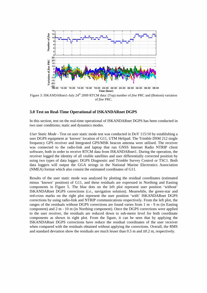
Figure 3: ISKANDARnet1-July 24th 2009 RTCM data: (Top) number of fine PRC and (Bottom) variation of fine PRC.
3.0 Test on Real-Time Operational of ISKANDARnet DGPS In this section, test on the real-time operational of ISKANDARnet DGPS has been conducted in two user conditions; static and dynamics modes. User Static Mode - Test on user static mode test was conducted in DoY 115/10 by establishing a user DGPS equipment at ‘known’ location of G11, UTM Helipad. The Trimble DSM 212 single frequency GPS receiver and Integrated GPS/MSK beacon antenna were utilised. The receiver was connected to the radio-link and laptop that run GNSS Internet Radio NTRIP client software, both in order to receive RTCM data from ISKANDARnet1. During the operation, the receiver logged the identity of all visible satellites and user differentially corrected position by using two types of data logger; DGPS Diagnostic and Trimble Survey Control or TSC1. Both data loggers will output the GGA strings in the National Marine Electronics Association (NMEA) format which also consist the estimated coordinates of G11. Results of the user static mode was analysed by plotting the residual coordinates (estimated minus ‘known’ position) of G11, and these residuals are expressed in Northing and Easting components in Figure 5. The blue dots on the left plot represent user position ‘without’ ISKANDARnet DGPS corrections (i.e., navigation solution). Meanwhile, the green-star and red-cross marks on the right plot represent the user position ‘with’ ISKANDARnet DGPS corrections by using radio-link and NTRIP communications respectively. From the left plot, the ranges of the residuals without DGPS corrections are found varies from 1 m - 9 m (in Easting component) and 2 m - 10 m (in Northing component). Once the DGPS corrections were applied to the user receiver, the residuals are reduced down to sub-metre level for both coordinate components as shown in right plot. From the figure, it can be seen that by applying the ISKANDARnet DGPS corrections have reduce the residual coordinates of the user receiver when compared with the residuals obtained without applying the corrections. Overall, the RMS and standard deviation show the residuals are much lesser than 0.5 m and ±0.2 m, respectively.
Var
iati
on o
f fi
ne P
RC
Time (hour)
Num
ber
of f
ine
PR
C
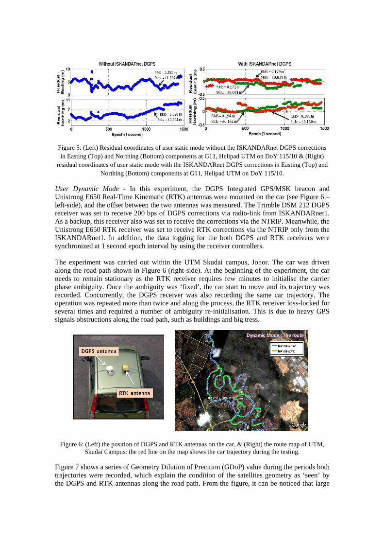
Figure 5: (Left) Residual coordinates of user static mode without the ISKANDARnet DGPS corrections in Easting (Top) and Northing (Bottom) components at G11, Helipad UTM on DoY 115/10 & (Right)
residual coordinates of user static mode with the ISKANDARnet DGPS corrections in Easting (Top) and Northing (Bottom) components at G11, Helipad UTM on DoY 115/10.
User Dynamic Mode - In this experiment, the DGPS Integrated GPS/MSK beacon and Unistrong E650 Real-Time Kinematic (RTK) antennas were mounted on the car (see Figure 6 – left-side), and the offset between the two antennas was measured. The Trimble DSM 212 DGPS receiver was set to receive 200 bps of DGPS corrections via radio-link from ISKANDARnet1. As a backup, this receiver also was set to receive the corrections via the NTRIP. Meanwhile, the Unistrong E650 RTK receiver was set to receive RTK corrections via the NTRIP only from the ISKANDARnet1. In addition, the data logging for the both DGPS and RTK receivers were synchronized at 1 second epoch interval by using the receiver controllers. The experiment was carried out within the UTM Skudai campus, Johor. The car was driven along the road path shown in Figure 6 (right-side). At the beginning of the experiment, the car needs to remain stationary as the RTK receiver requires few minutes to initialise the carrier phase ambiguity. Once the ambiguity was ‘fixed’, the car start to move and its trajectory was recorded. Concurrently, the DGPS receiver was also recording the same car trajectory. The operation was repeated more than twice and along the process, the RTK receiver loss-locked for several times and required a number of ambiguity re-initialisation. This is due to heavy GPS signals obstructions along the road path, such as buildings and big tress.
Figure 6: (Left) the position of DGPS and RTK antennas on the car, & (Right) the route map of UTM, Skudai Campus: the red line on the map shows the car trajectory during the testing.
Figure 7 shows a series of Geometry Dilution of Precition (GDoP) value during the periods both trajectories were recorded, which explain the condition of the satellites geometry as ‘seen’ by the DGPS and RTK antennas along the road path. From the figure, it can be noticed that large
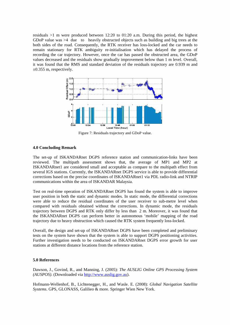
residuals >1 m were produced between 12:20 to 01:20 a.m. During this period, the highest GDoP value was >4 due to heavily obstructed objects such as building and big trees at the both sides of the road. Consequently, the RTK receiver has loss-locked and the car needs to remain stationary for RTK ambiguity re-initialisation which has delayed the process of recording the car trajectory. However, once the car has passed the obstructed area, the GDoP values decreased and the residuals show gradually improvement below than 1 m level. Overall, it was found that the RMS and standard deviation of the residuals trajectory are 0.939 m and ±0.355 m, respectively.
Figure 7: Residuals trajectory and GDoP value. 4.0 Concluding Remark The set-up of ISKANDARnet DGPS reference station and communication-links have been reviewed. The multipath assessment shows that, the average of MP1 and MP2 at ISKANDARnet1 are considered small and acceptable as compare to the multipath effect from several IGS stations. Currently, the ISKANDARnet DGPS service is able to provide differential corrections based on the precise coordinates of ISKANDARnet1 via PDL radio-link and NTRIP communications within the area of ISKANDAR Malaysia. Test on real-time operation of ISKANDARnet DGPS has found the system is able to improve user position in both the static and dynamic modes. In static mode, the differential corrections were able to reduce the residual coordinates of the user receiver to sub-metre level when compared with residuals obtained without the corrections. In dynamic mode, the residuals trajectory between DGPS and RTK only differ by less than 2 m. Moreover, it was found that the ISKANDARnet DGPS can perform better in autonomous ‘mobile’ mapping of the road trajectory due to heavy obstruction which caused the RTK system frequently loss-locked. Overall, the design and set-up of ISKANDARnet DGPS have been completed and preliminary tests on the system have shown that the system is able to support DGPS positioning activities. Further investigation needs to be conducted on ISKANDARnet DGPS error growth for user stations at different distance locations from the reference station. 5.0 References Dawson, J., Govind, R., and Manning, J. (2005): The AUSLIG Online GPS Processing System (AUSPOS). (Downloaded via http://www.auslig.gov.au). Hofmann-Wellenhof, B., Lichtenegger, H., and Wasle. E. (2008): Global Navigation Satellite Systems. GPS, GLONASS, Galilieo & more. Springer Wien New York.

Kaplan, E.D. and Hegarty, C.J. (2006): Understanding GPS, Principles and Application. Artech House Inc., Norwood, United State. Lenz, E. (2004): Networked Transport of RTCM via Internet Protocol (NTRIP) -Application and Benefit in Modern Surveying Systems. FIG Working Week. 22-27 May, Athens, Greece. The Institute of Navigation, Inc. (2008): GPS Modernization. ION GNSS 2007 Technical Program. (Downloaded via http://www.ion.org/search/theinstitudeofnavigation/). Wan Anom, W. A., Musa, T. A., Setan, H., Ses, S. (2008): UTMNAV: An Approach of DGPS Technique for Precise Navigation System. Proceeding of 7th International Symposium & Exhibition on Geoinformation (ISG 2008), Kuala Lumpur, Malaysia. Wan Anom, W. A., and Musa, T. A. (2008): Towards the Differential Global Positioning System (DGPS) Service for ISKANDAR Malaysia. Proceeding of Postgraduate Seminar, Faculty of Geoinformation Science & Engineering, Universiti Teknologi Malaysia, Johor, Malaysia. Acknowledgement The authors wish to thank the UTM-Research University Grant (RUG) & International GNSS Service (IGS) for supporting and contribution along the ‘The Development of ISKANDARnet GPS Services for Precise Real-Time Positioning Mapping & Navigation’ and GPS data source, respectively.