Embed Size (px)
Citation preview

Journal of Computer Science, 9 (4): 500-513, 2013
ISSN 1549-3636
© 2013 Science Publications
doi:10.3844/jcssp.2013.500.513 Published Online 9 (4) 2013 (http://www.thescipub.com/jcs.toc)
Corresponding Author: Kugalur Muthusamy Palaniswamy, Department of Electronics and Communication Engineering,
EXCEL Engineering College, Komarapalayam, Tamilnadu, India
500 Science Publications
JCS
The Optimistic Adaptive Modulation
Technique for Future Wireless Communication
1Kugalur Muthusamy Palaniswamy,
2Veerappa Gounder Palanisamy and
1Kugalur Muthusamy Palaniswamy
1Department of Electronics and Communication Engineering,
EXCEL Engineering College, Komarapalayam, Tamilnadu, India 2Veerappa Gounder, Palanisamy, Principal, Information and Communication Engineering,
INFO Institute of Engineering, Coimbatore, Tamilnadu, India
Received 2012-07-04, Revised 2013-01-20; Accepted 2013-05-13
ABSTRACT
The Future Wireless Communication requires 100 Mbits/s Data rate, streaming audio/video, asymmetric access/multiple access, Adaptive modulation and coding, dynamic packet arrangement, smart antenna adaptation andIPv6 facility to enhance error free communication. Various digital modulation techniques have been taken for simulation and bit error rate is calculated in both MC-CDMA System and OFDMA system. The continuous phase modulation techniques ensures large bandwidth, high data rate and error free data communication. The convolution coder is mainly chosen to facilitate the Wireless communication. The output from serial to parallel converter is inhibited to various Adaptive modulation schemes like M-ary PSK, M-ary QAM, M-ary CPM and M-ary MHPM systems. The modulated output is then fed to MC-CDMA System and OFDMA system in fast fading Rayleigh environment. The BER performance and SNR ratio are observed for both the MC-CDMA system and OFDMA System inhibiting various modulation schemes and the corresponding simulation result are plotted using Mat lab and Simulink software. The outputs of various modulation schemes are plotted for both OFDMA and MC-CDMA systems. It is found that MHPM is found to be the optimistic Adaptive modulation technique for future Wireless communication. Keywords: MC-CDMA-Multi Carrier Code Division Multiple Access, OFDMA-Orthogonal Frequency
Division Multiple Access, PSK-Phase Shift Keying, QAM-Quadrature Amplitude Modulation,
CPM- Continuous Phase Modulation, MHPM-Multi-Hop Phase Coded Modulation
1. INTRODUCTION
1.1. Performance
The Future mobile (4G) communication feature extremely high quality video with large bandwidth, high data rate and error free data communication. It also enables wireless download with speed of up to 100 mbps.
1.2. Interoperability
Since there are many standards in 3G Networks, It is difficult to roam and interoperate across networks. It is overcome by providing a Global standard and provides compatibility between various standards.
1.3. Networking
The Future Mobile (4G) Communications Network
will be a Hybrid Network which utilize both wireless Local
Area Access Network (LAN) concept and Wide Area
Access Network (WAN) in design process. The 4G network
enhances Internet Protocol version 6 (IPv6) and intended to
succeed IPv4.
1.4. Data Rate
4G facilitates transmission speed of more than 100
Mbits/s and offers higher bandwidth within the reach
of LAN.
Kugalur Muthusamy Palaniswamy et al. / Journal of Computer Science 9 (4): 500-513, 2013
501 Science Publications
JCS
1.5. Convergence
The Future Wireless Communication Utilizes IP in
full form with converged voice and data capability.
1.6. Cost
It will be cheaper than the existing 3G System as it
utilizes the most advanced technology in the existing
Network. It does not require the operators to purchase
extra spectrum.
1.7. Scalability
Scalability or the ability to handle increased no of users and diversity of services are easily achieved in the future Wireless communication as the IP core is easily scalable.
IPv6 supports globally unique static IP addresses, which can be used to track a single device's Internet activity. Since the devices are used mostly used by a single user, the device activity is often assumed to be equivalent to the user’s activity 4g-Encyclobedia, 4g-wikepedia. The Composite vision of 4G includes (Watson,
2000):
• 100 Mbits/s data rate • Streaming audio/video • Asymmetric access/multiple access. • Adaptive modulation/coding • Dynamic packet arrangement • Smart antenna adaptation. • IPv6 facility
1.8. Section-2
1.8.1. Importance of MC-CDMA and OFDMA
MC-CDMA and OFDMA are considered to be the best suited accessing techniques for future Wireless communication physical layer. It is recognized that future enhancements in Wireless communication includes the Inherent ability to support adhoc based Wireless networks.
Inter Symbol Interference (ISI) which Results due to the delay spread of the signal caused by multipath effects of the received signal is avoided by providing Guard Interval (GI) i.e., Pilot Symbol Insertion either in front end or back end with longer delay than the delay spread.
As the Wireless channel varies rapidly with time to time, the fixed channel modulation system becomes inefficient. Since it uses a higher order modulation format only during good channel condition, Adaptive modulation techniques are best suited to achieve efficient and effective communication over multipath fading transmission channels.
1.9. A-Subsection
1.9.1. Turbo Coder
The convolution coder i.e., TURBO Coder (High performance forward error correction coder) is selected to meet the dynamic channel capacity for noise free communication. It finds specific use where designers seek to achieve Information transfer over larger bandwidth and enhances latency constrained communication link. The encoder is implemented by sending three sub blocks of bits. The first Sub block is the m bit block of payload data. The second sub-block is n/2 parity bits for payload data computed using a Recursive Convolution Code (RSC) and the third sub block is n/2 parity bits for a known permutation of the payload data is computed using an RSC Convolution Code. The Turbo coder design parameters are given in the Table 1.
1.10. B-Subsection
1.10.1. Modulation Techniques
The combination of convolution coder, OFDMA system and MC-CDMA system with Adaptive modulation techniques (M-ary QAM, M-ary PSK, M-ary CPM and M-ary MHPM) in a free Rayleigh fading channel is taken and Signal to Noise Ratio (SNR) Vs Bit Error Rate (BER) is plotted for up to 32 users using Mat lab and Simulink software.
1.11. Relative Concept
If the fixed modulation technique is designed by considering a worst case scenario, the system may be good only for worst case scenario and during other times the system experiences very poor SNR. Hence it is decided to go for Adaptive modulation system with M-array techniques.
Taking advantage of the time varying nature of Wireless channels, the Adaptive modulation scheme varies transmission power, data rate, constellation size, coding and modulation scheme or combination of any of the parameters according to the state of the channel. The Adaptive modulation technique provides a good SNR during normal time and as the system worsens, the modulation scheme change its array accordingly as (M-array-2,4,8,16,32…..) and tune itself to provide good SNR.
1.12. C-Subsection
1.12.1. OFDMA Vs MC-CDMA Performance
For fully loaded system the OFDMA surpasses MC-CDMA in the error performance where as for a partially loaded system, MC-CDMA surpasses the OFDMA performance by utilizing its whole diversity of used sub-carriers.
Kugalur Muthusamy Palaniswamy et al. / Journal of Computer Science 9 (4): 500-513, 2013
502 Science Publications
JCS
Table 1. System parameters
Parameters Specifications
Channel bandwidth >20 mhz Frequency 5 GHZ No of subcarriers 1024 Subcarrier spacing 25 KHZ Portion of symbol 40 µs Cyclic extension duration 10 µs Total symbol duration 50 µs Symbol rate 640 ksymbol/s Chip rate 20.48 Mchip[s/s CDMA code Walsh hadamard Code length 32 chips Table 2. Channel parameters
Parameters Specifications
Mobile speed 100 km per hour Number of paths Four with Exponential power distribution Maximum excess delay 150 µs Decaying factor 10% of symbol duration Table 3. Turbo coder parameters
Parameters Specifications
Rate 1/3 Constraint length 3 Interleaving Block interleaving with block size 1024 bits Decoding MAP decoding with hard inputs In this case, MC-CDMA can even gain 2dB compared to OFDMA and hence it is found that both OFDMA and MC-CDMA are highly suited for multi cellular environment.
1.13. System Design Concept
1.13.1. System Design
The proposed OFDMA System and MC-CDMA system is designed by using the specified parameters given in the Table 2 below. The assumed frequency is 5GHz with a channel bandwidth of 20 MHz. The no of sub carriers is choosen as 1024 with subcarrier spacing of 25 kHz. The symbol rate is fixed as 640 ksymbols/s. The Walsh hadamard code is taken as PN sequence code containing 32 chips.
1.14. Chatterjee et al. (2003) Channel Parameters
The Rayleigh fading channel with a mobile speed of 100 km/h (Kilo Meter per hour) is taken and parameters are given in the Table 3 below. Here the signal takes four exponential paths with a decaying factor of 10% (Steele and Webb, 1991).
1.15. Coder Design
The 1/3 Turbo coder with a constraint length of 3 and block interleave with 1024 bits size are taken as design parameters for Coder design and MAP decoding with hard inputs (Chatterjee et al., 2003).
1.16. D-Subsection
1.16.1. Implementation of Adaptive modulation
techniques
Steele and Webb (1991) proposed burst by burst Adaptive Quadrature Amplitude Modulation (QAM) for exploiting the time variant Shannon Channel capacity of narrow band fading channels. The above system sacrificed the bit error rate for getting better fixed data throughput. Keller and Hanzo (1998) proposed Adaptive modulation techniques with a set of QPSK and QAM modulation Schemes for OFDM duplex transmission where as Wasantha (2000) has proposed an Adaptive COFDM-CDMA system with QAM, PSK and MHPM modulation schemes. Wasantha and Fernando (2002), Adaptive modulation improves the system throughput considerably by matching transmitter parameters to time-varying wireless fading channels.
1.17. Features of Adaptive Modulation
RF power output has been a major planning aspect for engineers since from the beginning of radio transmission. Undoubtedly important, RF power level is one of the many factors that determine a successful wireless network. To evaluate and differentiate between various microwave systems and link performance, several key aspects of RF power output. Propagation and antenna parameters such as receiver threshold, modulation type and RF power level are to be considered. Adaptive modulation schemes and Automatic Transmit Power Control (ATPC) provide point-to-point microwave systems with a high degree of flexibility and ensures better efficiency under changing weather conditions. RF output power can be controlled dynamically so as to ensure the highest power efficiency under changing modulation. The goal of Adaptive modulation is to improve the operational efficiency of microwave links by increasing network capacity over the existing infrastructure and reduce sensitivity to environmental interference. Adaptive modulation means dynamically varying the modulation in an errorless manner in order to maximize the throughput under momentary propagation conditions. In other words, a system can operate at its maximum throughput under clear sky conditions and decrease it gradually under rain fade.
Kugalur Muthusamy Palaniswamy et al. / Journal of Computer Science 9 (4): 500-513, 2013
503 Science Publications
JCS
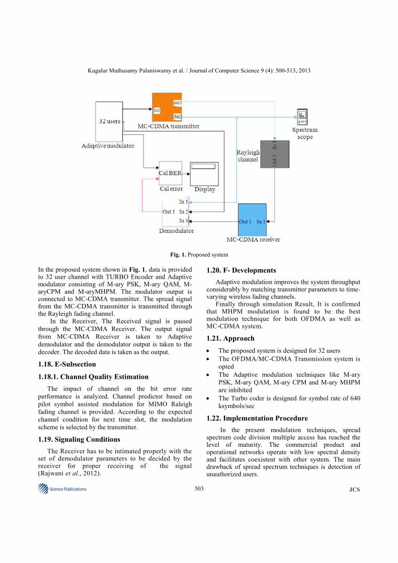
Fig. 1. Proposed system
In the proposed system shown in Fig. 1, data is provided to 32 user channel with TURBO Encoder and Adaptive modulator consisting of M-ary PSK, M-ary QAM, M-aryCPM and M-aryMHPM. The modulator output is connected to MC-CDMA transmitter. The spread signal from the MC-CDMA transmitter is transmitted through the Rayleigh fading channel. In the Receiver, The Received signal is passed
through the MC-CDMA Receiver. The output signal
from MC-CDMA Receiver is taken to Adaptive
demodulator and the demodulator output is taken to the
decoder. The decoded data is taken as the output.
1.18. E-Subsection
1.18.1. Channel Quality Estimation
The impact of channel on the bit error rate
performance is analyzed. Channel predictor based on
pilot symbol assisted modulation for MIMO Raleigh
fading channel is provided. According to the expected
channel condition for next time slot, the modulation
scheme is selected by the transmitter.
1.19. Signaling Conditions
The Receiver has to be intimated properly with the set of demodulator parameters to be decided by the receiver for proper receiving of the signal (Rajwani et al., 2012).
1.20. F- Developments
Adaptive modulation improves the system throughput considerably by matching transmitter parameters to time-varying wireless fading channels.
Finally through simulation Result, It is confirmed that MHPM modulation is found to be the best modulation technique for both OFDMA as well as MC-CDMA system.
1.21. Approach
• The proposed system is designed for 32 users
• The OFDMA/MC-CDMA Transmission system is
opted
• The Adaptive modulation techniques like M-ary
PSK, M-ary QAM, M-ary CPM and M-ary MHPM
are inhibited
• The Turbo coder is designed for symbol rate of 640
ksymbols/sec
1.22. Implementation Procedure
In the present modulation techniques, spread spectrum code division multiple access has reached the level of maturity. The commercial product and operational networks operate with low spectral density and facilitates coexistent with other system. The main drawback of spread spectrum techniques is detection of unauthorized users.

Kugalur Muthusamy Palaniswamy et al. / Journal of Computer Science 9 (4): 500-513, 2013
504 Science Publications
JCS
Fig. 2. Simple modulator in Rayleigh fading environment
The drawback can be overcome in OFDM system
by implementation of following steps:
• The serial to parallel converted data stream is spread by
using the given spreading code and then different
subcarriers are modulated with each data stream • The use of conventional CDMA is not applicable as
the data rate goes above 100 Mbits/s due to severe intercede interference. The solution for the above problem is achieved by finding a new technique called Adaptive modulation technique which reduces both the symbol rate and the chip rate.
• The common point is to change the conventional serial transmission of data/chip stream in to parallel transmission of data/chip symbols over large number of narrowband orthogonal carriers. Hence the chip and bit duration is increased proportionally
The Fig. 2 represents the simple Transmitter with data
source, transmitter and channel. Here the Random integer
generator is chosen as source to provide necessary data to
Adaptive modulator for modulation. The modulated data is
spreaded using MC-CDMA transmitter and passed through
the Rayleigh fading channel.
Rayleigh fading is used in heavily built-up city centers
where there is no line of sight between the transmitter and receiver. The buildings and other objects attenuate, reflect, refract and diffract the signal. In troposphere and ionosphere signal propagation, the particles in the atmospheric layers act as scatterers and this kind of environment may also approximate Rayleigh fading. The
Output from Rayleigh fading channel is taken to scope for display. (en.wikipedia.org/wiki/Rayleigh_fading) The various types of Adaptive modulation schemes
selected for transmission system are QPSK QAM,CPM
and MHPM system and their descriptions, are listed
below (Xiong, 2006).
1.23. QPSK
1.23.1. M-Ary Phase-Shift Keying
• Phase-Shift Keying (PSK) is a digital modulation
scheme that conveys data by changing, or
modulating, the phase of a reference signal (the
carrier wave)
• Usually, each phase encodes an equal number of
bits. Each pattern of bits forms the symbol is
represented by the particular phase
• The demodulator, which is designed specifically for
the symbol-set used by the modulator, determines
the phase of the received signal and maps it back to
the symbol it represents and recovers the original
data. If the receiver is able to compare the phase of
the received signal to a reference signal, such a
system is termed coherent PSK (referred as CPSK)
1.24. QAM
1.24.1. QAM
• It has both an analog and a
digital modulation scheme. It conveys two analog
message signals, or two digital bit streams by
changing (modulating) the amplitudes of two carrier
waves, using the Amplitude-Shift Keying (ASK)
or amplitude Modulation (AM)
• The two carrier waves, usually sinusoids, are out of
phase with each other by 90 degree and are thus
called quadrature carriers. The modulated waves are
summed and the resulting waveform is the
combination of both Phase Shift Keying (PSK)
and amplitude-Shift Keying (ASK).
1.25. Continuous Phase Modulation (CPM)
• CPM called as constant envelope waveform
method is mostly used in wireless modems
• In contrast to other coherent digital phase
modulation techniques where the carrier phase
abruptly resets to zero at the start of every symbol
(example-M-PSK), here in CPM, The carrier phase
is modulated in a continuous manner
• As the transmitted carrier power is maintained
constant, the phase continuity yields high spectral
efficiency and the constant envelope yields high
power efficiency

Kugalur Muthusamy Palaniswamy et al. / Journal of Computer Science 9 (4): 500-513, 2013
505 Science Publications
JCS
Fig. 3. OFDMA transmitter
Fig. 4. OFDMA receiver
1.26. Multi-H Phase Coded Modulation (MHPM)
• MHPM scheme was first explained in detail by Anderson and Taylor. It is a bandwidth efficient modulation scheme which offers substantial coding gain over conventional digital modulations
• Here modulation indices are used in a prescribed manner such that the transmitted signal has phase slope variation changing from one symbol interval to the next in response to the data symbols being transmitted. The Trellis paths will results in longer minimum Euclidean distances for MHPM schemes provides the coding gain as compared to other conventional Modulation schemes (Watson, 2000)
1.27. OFDMA and MC-CDMA Implementation
The serial data is converted to parallel data streams before modulated on to subcarriers. The sub carriers are then sampled at a rate of N/Ts. The samples on each carrier are summed together to form an OFDM sample.
An OFDM sample is generated by an N-Sub carrier OFDM system consists of N samples and the m
th sample
of an OFDM symbol (Keller and Hanzo, 2000):
( )N 1
j2xmn/N
m
n 1
X Xne 0 m n 1−
−
= < < −∑
where, Xn = Transmitted data symbol on m
th carrier.
The base band signal thus created is modulated by a carrier to become a band pass signal before transmission: • The original data is spread using a spreading code
and then different sub carriers are modulated with
each chip. A fraction of the symbol corresponding to the chip of the spreading code is transmitted through a different sub carrier
• The transmitter and receiver scheme of OFDMA and MC-CDMA differs only in sub carrier allocation, addition and detection of components of MC-CDMA transmission scheme
• The information bit stream of NU active users are mapped to complex valued data symbols
• In the subcarrier allocation Nd symbols per user are arranged for each transmission scheme. In case of MC-CDMA the K
th data symbol is multiplied by Walsh
Hadamard spreading sequence and provide chips
• The spreading length varies accordingly with
maximum no of active user (i.e.) L=NU (max)
• Finally OFDM modulation is performed by using
Inverse Fast Fourier Transform (IFFT), which
results in addition of Guard Interval (GI) to avoid
Intersymbol Interference (ISI) and Interchannel
Interference (ICI) in the receiver • In the receiver side the transmission process is
reversed for the detection of original signal
• In MC-CDMA the distortion due to flat fading on
each sub channel is compensated by equalization.
The coded bits are deinterleaved and finally decoded
(Chen and Wang, 2001)
In Fig. 3 and 4, OFDMA, subcarriers are grouped
into larger units, referred to as sub channels and these
sub channels are further grouped into bursts which can
be allocated to wireless users. Each burst allocation can
Kugalur Muthusamy Palaniswamy et al. / Journal of Computer Science 9 (4): 500-513, 2013
506 Science Publications
JCS
be changed from frame to frame as well as within the
modulation order. This allows the base station to
dynamically adjust the bandwidth usage according to the
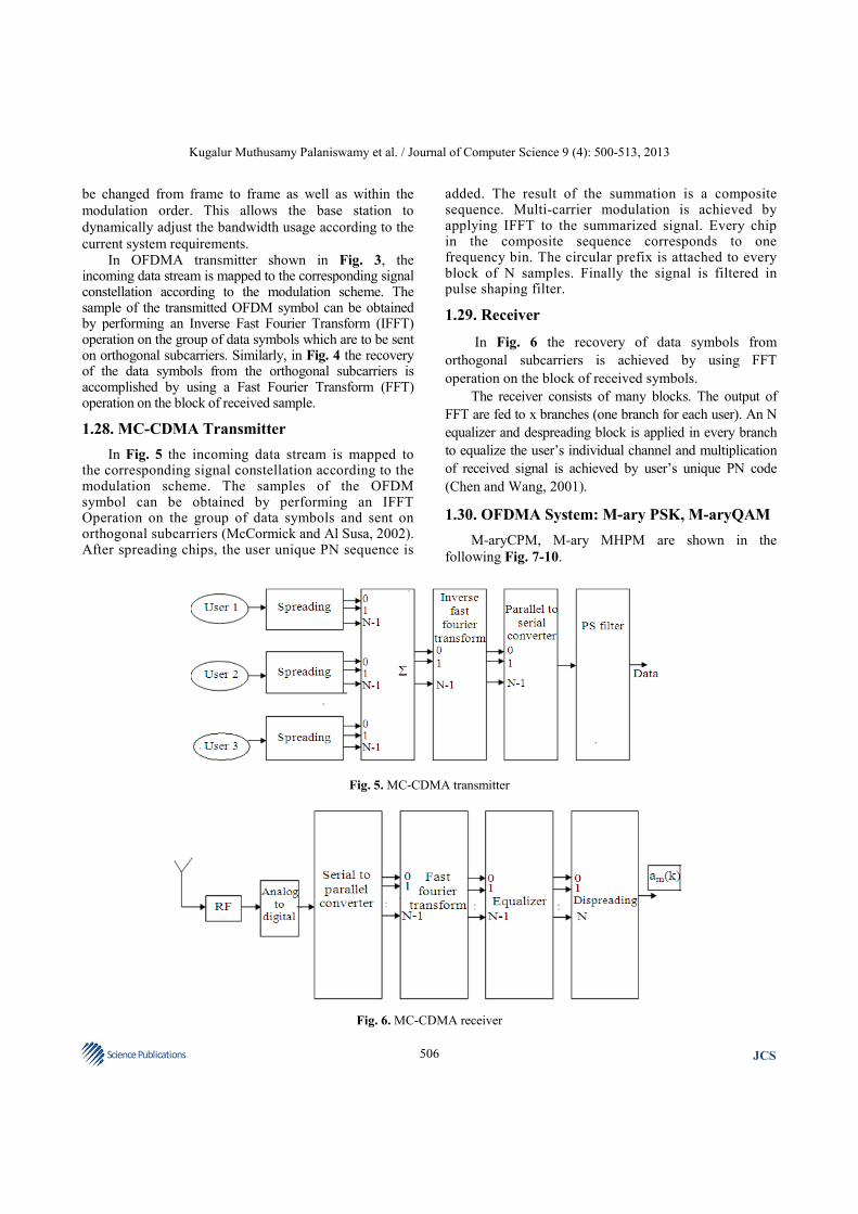
current system requirements. In OFDMA transmitter shown in Fig. 3, the incoming data stream is mapped to the corresponding signal constellation according to the modulation scheme. The sample of the transmitted OFDM symbol can be obtained by performing an Inverse Fast Fourier Transform (IFFT) operation on the group of data symbols which are to be sent on orthogonal subcarriers. Similarly, in Fig. 4 the recovery of the data symbols from the orthogonal subcarriers is accomplished by using a Fast Fourier Transform (FFT) operation on the block of received sample.
1.28. MC-CDMA Transmitter
In Fig. 5 the incoming data stream is mapped to the corresponding signal constellation according to the modulation scheme. The samples of the OFDM symbol can be obtained by performing an IFFT Operation on the group of data symbols and sent on orthogonal subcarriers (McCormick and Al Susa, 2002). After spreading chips, the user unique PN sequence is
added. The result of the summation is a composite sequence. Multi-carrier modulation is achieved by applying IFFT to the summarized signal. Every chip in the composite sequence corresponds to one frequency bin. The circular prefix is attached to every block of N samples. Finally the signal is filtered in pulse shaping filter.
1.29. Receiver
In Fig. 6 the recovery of data symbols from
orthogonal subcarriers is achieved by using FFT
operation on the block of received symbols.
The receiver consists of many blocks. The output of
FFT are fed to x branches (one branch for each user). An N
equalizer and despreading block is applied in every branch
to equalize the user’s individual channel and multiplication
of received signal is achieved by user’s unique PN code
(Chen and Wang, 2001).
1.30. OFDMA System: M-ary PSK, M-aryQAM
M-aryCPM, M-ary MHPM are shown in the
following Fig. 7-10.
Fig. 5. MC-CDMA transmitter
Fig. 6. MC-CDMA receiver

Kugalur Muthusamy Palaniswamy et al. / Journal of Computer Science 9 (4): 500-513, 2013
507 Science Publications
JCS
Fig. 7. OFDMA SystemM-ary PSK
Fig. 8. OFDMA System M-ary QAM

Kugalur Muthusamy Palaniswamy et al. / Journal of Computer Science 9 (4): 500-513, 2013
508 Science Publications
JCS
Fig. 9. OFDMA System M-ary CPM
Fig. 10. OFDMA System M-ary MHPM

Kugalur Muthusamy Palaniswamy et al. / Journal of Computer Science 9 (4): 500-513, 2013
509 Science Publications
JCS
Fig. 11. MC-CDMA System M-ary PSK
Fig. 12. MC-CDMA System M-ary QAM

Kugalur Muthusamy Palaniswamy et al. / Journal of Computer Science 9 (4): 500-513, 2013
510 Science Publications
JCS
Fig. 13. MC-CDMA system Mary MHPM
Fig. 14. MC-CDMA System M-ary CPM
Kugalur Muthusamy Palaniswamy et al. / Journal of Computer Science 9 (4): 500-513, 2013
511 Science Publications
JCS
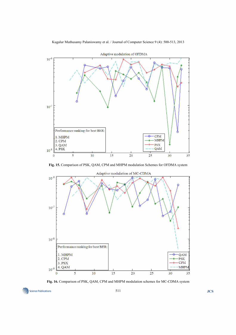
Fig. 15. Comparison of PSK, QAM, CPM and MHPM modulation Schemes for OFDMA system
Fig. 16. Comparison of PSK, QAM, CPM and MHPM modulation schemes for MC-CDMA system

Kugalur Muthusamy Palaniswamy et al. / Journal of Computer Science 9 (4): 500-513, 2013
512 Science Publications
JCS
1.31. MC-CDMA System Mary-PSK, M-ary
QAM
Mary-CPM and M-ary-MHPM Systems are shown
in the following Fig. 11-14.
1.32. OFDMA System and MC-CDMA System
The BER Vs No of User’s of various Adaptive
modulation techniques for both OFDMA system and
MC-CDMA system are plotted for up to 32 users. The
BDBP is constantly maintained at 640ksymbols/sec. The
Comparative graphs are shown in the Fig. 15 and 16.
2. MATERIALS AND METHODS
The OFDMA and MC-CDMA transmitter and
receiver are designed by using the above parameters
given in Table 1-3. The 1/3 rated Turbo coder is selected
in transmitter. The symbol rate of 640 ksymbols/sec is
maintained and the simulation is performed using Mat
lab and Simulink software (Chatterjee et al., 2003).
3. RESULTS AND DISCUSSION
From the graphical analysis, it is clear that the M-
aryCPM and M-aryMHPM modulation techniques are
providing BER of up to 10−8
as compare to M-ary PSK
and M-ary QAM which can provide a BER result of up
to 10−5
. From the graph it is found that For OFDMA
system, the modulation techniques ranks in following
hierarchy of MHPM, CPM, QAM and PSK where as for
MC-CDMA system, the modulation techniques ranks as
MHPM, CPM, PSK and QAM.
The simulation is performed using Mat lab and
Simulink software and the simulation results for
OFDMA and MC-CDMA system are plotted for M-
ary PSK, M-ary QAM. Mary CPM and M-ary MHPM
for up to 32 users for symbol rate of 640ksymbols/sec.
The number of users Vs BER curves are plotted for all
the modulation techniques of MC-CDMA system and
OFDMA System. The overall comparative graph for
both MC-CDMA system and OFDMA system are
plotted. From both the comparative graph it is found
that M-ary MHPM modulation technique is found to
be the best Adaptive modulation technique for both
MC-CDMA and OFDMA system.
4. CONCLUSION
Adaptive modulation based MC-CDMA System
or OFDMA System using Turbo encoder is taken in
Rayleigh fading environment and the simulation result
is plotted. The BER for Mary PSK, M-ary QAM, M-
ary MHPM and M-ary CPM for BDBP (Bit Duration
Bandwidth Product) 640 ksymbols/sec is analyzed.
It is found that M-ary MHPM has very low BER of
up to 10−7
. It is found that the dynamic switching
technique of Adaptive modulation has made the BER to
be maintained within the lowest limit. The Turbo coder
with a rating of 1/3 has made the system to work in
adhoc environment very effectively and maintain a
constant BER.
So it is concluded that MHPM based Adaptive
modulation system with 1/3{One by three} rated Turbo
coder seems to be the best suited modulation system for
both MC-CDMA and OFDMA accessing techniques.
5. REFERENCES
Chatterjee, S., W.A.C. Fernando and M.K. Wasantha,
2003. Adaptive modulation based MC-CDMA
systems for 4G wireless consumer applications.
IEEE Trans. Consumer Electr., 49: 995-1003. DOI:
10.1109/TCE.2003.1261187
Chen, J. and Y. Wang, 2001. Adaptive MLSE equalizers
with parametric tracking for multipath fast-fading
channels. IEEE Trans. Commun., 49: 655-663. DOI:
10.1109/26.917772
Keller, T. and L. Hanzo, 1998. Adaptive orthogonal
frequency division multiplexing schemes.
Proceedings of the Adaptive Orthogonal Frequency
Division Multiplexing Schemes, (ACTS’ 98),
Rhodos, Greece, pp: 794-799.
Keller, T. and L. Henzo, 2000. Adaptive modulation
techniques for duplex OFDM transmission. IEEE
Tran. Vehicular Technol., 49: 1893-1906. DOI:
10.1109/25.892592
McCormick, A.C. and E.A. Al Susa, 2002. Multicarrier
CDMA for Future generation mobile
communication. Electr. Commun. Eng. J., 14: 52-60.
DOI: 10.1049/ecej: 20020202
Rajwani, I., P.U. Dere and A. Deshpande, 2012.
OFDMA based communication system with low
peak average power ratio. Int. J. Eng. Res. Applic.,
2: 1876-1879.

Kugalur Muthusamy Palaniswamy et al. / Journal of Computer Science 9 (4): 500-513, 2013
513 Science Publications
JCS
Steele, R. and W. Webb, 1991. Variable rate QAM for
data transmissions over Rayleigh fading channels.
Proceedings of the Wireless, (Wireless’ 91),
Calgary, Canada, pp: 1-14.
Wasantha, M.K. and W.A.C. Fernando, 2002. Adaptive
modulation techniques for COFDM-CDMA based
wireless networks. Proceedings of Wireless Personal
Multimedia Communication, (WPMC’ 02),
Honolulu, Hawaii.
Wasantha, M.K., 2000. Adaptive modulation techniques for OFDM-CDMA based 4G mobile networks. Master Thesis, Asian Institute of Technology, Thailand.
Watson, D., 2000. Mood and Temperament. 1st Edn., Guilford Press, New York, ISBN-10: 1572305266, pp: 340.
Xiong, F., 2006. Digital Modulation Techniques. 2nd Edn., Artech House, Boston, MA., ISBN-10: 1580538630, pp: 1017.