Embed Size (px)
Citation preview

Num. …
Anno XXXIII – Speciale CTA 2015 – Num. 3
___________________ *Corresponding author: Maria Rosaria Pecce, Department of Engineering, University of Sannio, Benevento, Italy. Email: [email protected]
International Journal of Earthquake Engineering
THE NON-LINEAR RESPONSE OF STEEL-CONCRETE COMPOSITE JOINTS
Maria Rosaria Pecce*
Department of Engineering – University of Sannio Piazza Roma 21, Benevento, Italy
SUMMARY: In this paper the experimental results of two beam-column composite connections (one welded and the other bolted) tested under cyclic loading are presented and discussed. The two full-scale specimens were designed as sub-assemblages of a frame to localize the damage at the end of the composite beam in respect of the capacity design, therefore the joint contributed to the deformability of the system essentially in the elastic field. The detail in the area around the column were realized according to the provisions of Eurocode 8 to assure the strength hierarchy by the local mechanisms of the concrete slab. The results highlight the main role of the composite beam in terms of ductility; the rotational capacity and an “equivalent” plastic hinge length are evaluated. KEYWORDS: steel-concrete frames, nonlinear response, composite joints, plastic hinge length
1. INTRODUCTION
In Moment Resisting Frame (MRF) solutions, an optimal seismic performance of the structure can be attained when a global mechanism is achieved at the ultimate limit state. This result is effective in RC structures when the dissipative mechanism involves all ends of the beams and column bases (global mechanism), conversely for steel and steel-concrete composite constructions the dissipation of the beams can be substituted by the one of the joint panels, as clearly provided by Eurocode 8 [Eurocode 8,2004] and confirmed in various studies [as example Bursi and Gramola, 2000, Thermou et al. 2004; Aribert et al, 2006;Braconi et al, 2008; Braconi et al. 2008]. However, for the steel-concrete composite frames, the Italian code [NTC2008] allows only the plasticization of the beam ends; therefore the capacity design method is suggested to obtain a weak beam-strong column behaviour in the MRF global mechanism. This result is exploited if a suitable hierarchy is realized between the beams and joints/columns, which ensures a ductile and stable response of the dissipative elements [D’Aniello et al., 2012]; thus a detailed design of the composite joint is of paramount importance to realize a reliable over strength respect to the beam. Currently the code provisions for the design of the composite joints and the knowledge from the research are still lack and usually referred to bolted connection where the dissipation is located in the steel parts of the joint (nodal panel, bolted plate) [Lee et al. 1989; Simões et al. 2001, Green et al. 2004; Salvatore et al, 2005; Vasdravellis et al, 2009].Therefore tests on two composite beam-column connections have been carried out by the author addressing the

INGEGNERIA SISMICA – INTERNATIONAL JOURNAL OF EARTHQUAKE ENGINEERING
67
dissipation in the beam [Pecce and Rossi, 2015],within the activity of a research project funded by the Italian Civil Defence (RELUIS project).This paper presents an analysis of the experimental results of the two full-scale composite joints (one bolted and one welded) that have been tested under cyclic loading, focusing on the relation between the design according to Eurocode 8 and the effective performance, but also examining in detail the inelastic performance of the beam.
2. THE EXPERIMENTAL TESTS
2.1 The specimens
The specimens were designed to represent a full scale sub-assemblage of a frame (Fig. 1), which includes not only an external joint, but also the two half columns of the adjacent floors and a part of the beam for a length longer than the critical zone and significant of the position of the zero bending moment, when vertical and seismic loads are applied (i.e., of the gradient of the bending moment).The forces loading the sub-assemblage in the real structure, the shear and axial forces at the points of the zero moments, have been applied during the tests; therefore, the experimental results provide the effective deformability of the entire frame in terms of the rotation (θ) that governs the interstorey drift, and is due to various contributions in the elastic and plastic field:
jcb
(1)
that are the rotation of the beam, the column and the joint, respectively. An exterior joint was selected for the test because exterior joints have exhibited some pinched hysteresis loops, whereas the cyclic behaviours of interior joints are usually more stable. Two full-scale composite joints (Fig. 2a) were constructed, one flanged (FJ) and the other welded (WJ). The specimen FJ was characterized by an extended end plate connection (Fig. 2b), whereas the specimen WJ was characterized by the steel beam directly welded to the column (Fig. 2a and 2c).
Figure 1. Scheme of the sub-assemblage

G. De MATTEIS and G. BRANDO
68
Table 1. Properties of the materials
Material design strength
(MPa) experimental average values
(MPa) Concrete (C20/25) 20/1.5 24.3 fy ft εu Steel for RC 450/1.15 460 549 15.3 Construction steel (flanges) 275/1.05 309 419 17.3 Construction steel (web) 275/1.05 394 481 13.6
The specimens were designed according to the European codes [Eurocode 4, 2004, Eurocode 8, 2004], applying the hierarchy of resistance for addressing the damage at the end of the beam. The beam section is depicted in Fig. 2d); the column was realized with a wide flange steel profile (HE280B) of height 280mm, web and flange thickness equal 10.5 mm and 18 mm respectively. The mechanical properties of the materials used for the construction of the specimen are reported in Table 1 introducing their design value and the average experimental strength.
2.2 The design of the specimen
The steel profile of the beam is in class 1 [Eurocode 3, 2005], however the composite beam becomes of class 2 when the hogging moment is applied and the height of web in compression overcomes the half height of the steel section; anyway the plastic moment can be assumed as flexural strength of the composite section. In Table 2 the plastic moments of the section are reported assuming the design values of the materials strength (i.e. the nominal characteristics values of the materials strength divided by the safety factors 1.5, 1.15 and 1.05 for concrete, RC steel and construction steel, respectively); the plastic moment is evaluated also considering the average values of the materials strength of Table 1 (the strength of the flange has been assumed for the entire profile) and reported in the same Table 2. Furthermore the flexural strength of the joint has been calculated considering the mechanisms around the column provided by Eurocode 8 for an exterior joint without the transversal beam; in fig. 3 the case of the positive and negative moments are schematized respectively. In particular for the sagging moment the mechanism 1 and 2 are considered (fig. 3.a) that surely are active when the beam slab has a concrete cantilever out of the column; analogously the mechanisms of fig. 3.b are active for the hogging moment (Amadio et al. 2015). The steel panel of the joint defined in the column web has been strengthen with plates on the two sides only in FJ to assure the beam-joint hierarchy; these plates haven’t been applied to WJ to verify the importance of this detail on the capacity design.
Table 2. Flexural resistance of the beam Plastic moment (kNm)
design strength of materials
average strength of materials
RdM
RdM RM
RM
189 152 260 179
INGEGNERIA SISMICA – INTERNATIONAL JOURNAL OF EARTHQUAKE ENGINEERING
69
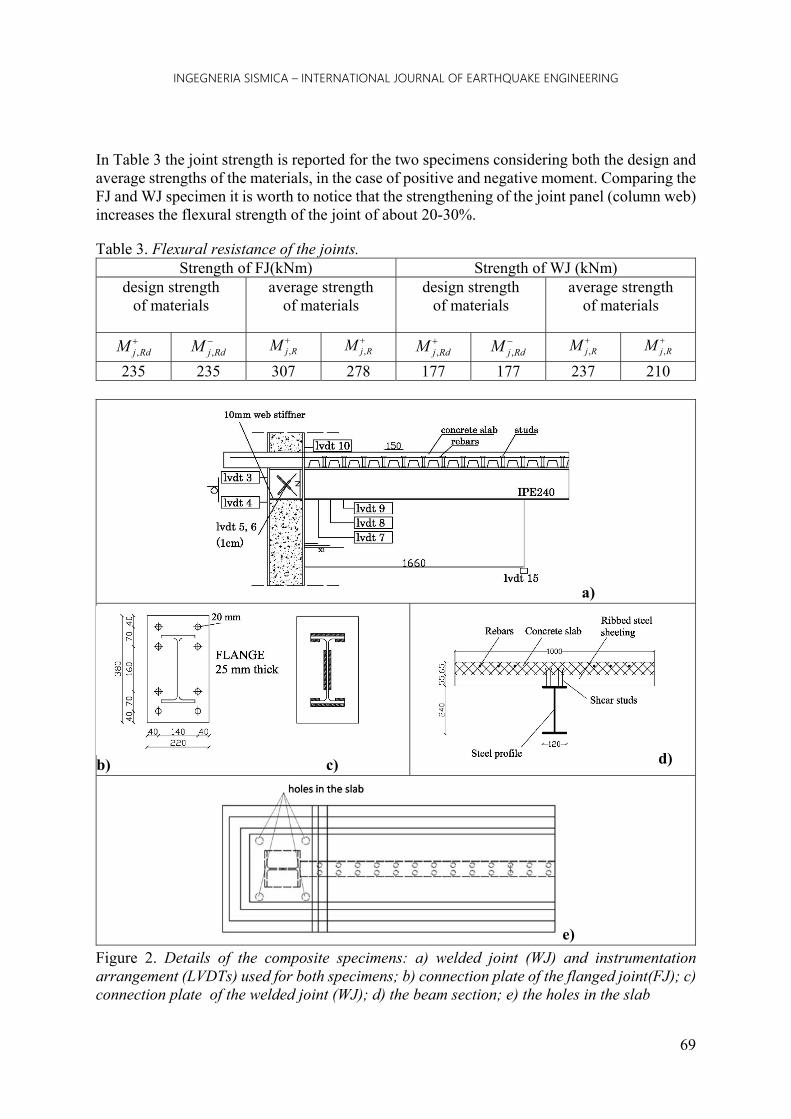
In Table 3 the joint strength is reported for the two specimens considering both the design and average strengths of the materials, in the case of positive and negative moment. Comparing the FJ and WJ specimen it is worth to notice that the strengthening of the joint panel (column web) increases the flexural strength of the joint of about 20-30%.
Table 3. Flexural resistance of the joints. Strength of FJ(kNm) Strength of WJ (kNm)
design strength of materials
average strength of materials
design strength of materials
average strength of materials
RdjM ,
RdjM , RjM ,
RjM , RdjM ,
RdjM , RjM ,
RjM ,
235 235 307 278 177 177 237 210
a)
b) c) d)
e)
Figure 2. Details of the composite specimens: a) welded joint (WJ) and instrumentation arrangement (LVDTs) used for both specimens; b) connection plate of the flanged joint(FJ); c) connection plate of the welded joint (WJ); d) the beam section; e) the holes in the slab

G. De MATTEIS and G. BRANDO
70
Comparing the flexural strength of the beam and joint (Table 2 and 3) it results that the beam-joint hierarchy (joint stronger than beam with safety factor according Eurocode 8) is respected in the design of FJ for the positive and negative moment, while is respected in the design of WJ only for the negative moment. The result is the same when the average strength is assumed for the materials. The resistance of the welds in the specimen WJ and the bolts with the end plate in the specimen FJ is greater than the beam resistance according to rules provided by Eurocode 8 for the capacity design.
2.3 The load history and the set-up
The experimental program is more detailed in [Pecce and Rossi, 2015] while in this paper, a brief description of the tests is provided to discuss the main results and the behavioural aspects. The specimens were tested under a cyclic load applied at the end of the beam. The column of the specimen FJ was loaded with an axial compression equivalent to 15% of its axial strength by a hydraulic handling jack; the axial load wasn’t applied to the specimen WJ in order to avoid the influence of the holes realized in the concrete slab to allow the crossing of the bars for its application (Fig.2.e). The test procedure was based on the ATC-24 protocols (Report No. ATC-24 – 1992);the cycles were established in 11 steps: three cycles per step until step number five and two cycles per step thereafter. The designed sequence of the step amplitude was based on the theoretical yielding displacement (dy); 3 equal cycles have been applied for displacement amplitudes of 0.25dy ,0.5dy, 0.75dy; dy, 2dy then 2 equal cycles have been applied for each assigned displacement.
Figure 3. Failure mechanisms of the slab at the joint. a) positive moment. b) negative moment

INGEGNERIA SISMICA – INTERNATIONAL JOURNAL OF EARTHQUAKE ENGINEERING
71
The yielding displacement, i.e. when the yielding moment My is achieved in the composite beam, was evaluated by a simple FE mono-dimensional model in SAP2000, where the deformability of the joint was introduced as estimated by the component method [Amadio et al., 2011],obtaining an higher value for the specimen FJ that is more deformable, but the yielding displacement of the specimen WJ under sagging moment (that is approximatively 13mm), i.e. the lower one, was assumed for both cases and assigned symmetrically for the positive and negative load. The experimental tests were stopped at a cyclic history of approximately 5-6dy, because local failure or global distortion of the specimens were attained, as discussed in the next paragraph. The vertical load was applied to the beam by a 500 kN-capacity hydraulic actuator with an available stroke of +/-250 mm. Many parameters were recorded during the tests; in particular a combination of linear transducers and strain gauges was deployed to identify the experimental behaviour of the joints. The general arrangement of the LVDTs is depicted in figure 2.a.
2.3 Cyclic behaviour and failure mode
In Figure 4 the cyclic response of the two specimens is drawn as the relation between the applied load and the displacement at the beam end. It can be observed that the behaviour of WJ is stiffer than the one of FJ in the elastic range especially under the positive moment; furthermore the shape of the hysteresis curves shows a greater phenomenon of pinching for the specimen FJ due to the slippage of the bolted flange. The collapse of the specimen FJ was due to the fracture in the bottom flange (fig. 4.a) near the weld and in the web after local buckling. Also for the specimen WJ, the local buckling of the flange in compression occurred (fig. 4.b); the last cycle was also characterized by the lateral-torsional buckling of the specimen due to the extensive damage in the concrete slab and the loss of its effective restraint, therefore the test was stopped. The local buckling wavelength for both specimens was measured and resulted similar to the height of the steel section (240 mm). Table 4 summarizes the main experimental results of the global behaviour: the displacement and load at yielding (dy and Fy), the maximum load and the corresponding displacement (Fmax and dmax), the ultimate displacement (du) that is the maximum displacement measured with a reduction of the load lower the 15% of the maximum one. The yielding load was identified by the yielding of the rebars for the hogging moment and the bottom steel flange for the sagging moment.
Figure 4. Cyclic response of the joints: a) the specimen FJ (fracture and local buckling), b) the specimen WJ (local buckling)

G. De MATTEIS and G. BRANDO
72
Table 4. Main experimental results dy+ dmax+ du+ du+/dy+ Fy+ Fmax+ My+ Mmax+
ID [mm] [mm] [mm] [-] [kN] [kN] [kN] [kN] FJ (M+) 23 35 90 3.91 119 137 198 227 WJ (M+) 12 66 73 6.08 115 165 191 274
dy- dmax- du- du-/dy- Fy- Fmax- My- Mmax- Id [mm] [mm] [mm] [-] [kN] [kN] [kN] [kN]
FJ (M-) -30 -88 -88 2.93 -85 -118 -141 -196 WJ (M-) -28 -50 -98 3.50 -101 -115 -168 -191
The maximum load was identified with the pick load. The sign indicates the sign of the bending moment in the composite beam: positive when the RC slab is in compression and negative when the RC slab is in tension. The maximum load results quite equal for the two specimens under the hogging moment while it is lower for FJ respect to WJ under sagging moment since the holes realized in the concrete slab to apply the axial load to the column, reduced the slab strength in compression i.e. the flexural strength of the section. The yielding and maximum load were multiplied by the distance of the force from the edge of the column, which is 1.66 m, to calculate the corresponding experimental moments (My and Mmax).
2.3 Comparison with the theoretical strength of the beam and joint
The experimental maximum moments can be compared with the plastic moments evaluated using the average strength of the materials. Comparison of the values of Tables 2 and 4 reveals that the maximum experimental moment is greater than the theoretical plastic moment of the beam, except than in the case of the sagging moment for the specimen FJ, presumably due to the local crashing of the concrete weaker for the presence of the holes. This higher values of the experimental strength is surely due to the hardening of steel that was neglected in the theoretical calculation; in all cases the average strength of the joint (Table 3) was not reached except than for the specimen WJ under the sagging moment. It means that the beam-joint hierarchy was respected in the FJ specimen, and also in the WJ for the hogging moment, as designed, while for the sagging moment the yielding of WJ occurred before the beam plasticization. However, the plasticization of the joint and beam under sagging moment was attained about contemporary, furthermore the degradation of the concrete slab and the hardening of the steel joint, allowed the complete plasticization of the beam preventing the load increasing and stopping the plastic deformation of the joint. Finally the theoretical yielding moment of the beam was evaluated with the elastic distribution of the stresses along the composite section; in the case of sagging moment the steel yielding (fy) at the bottom fiber of the steel profile is reached, whereas in the case of the hogging moment the yield of the section corresponds to the yielding of the rebars. Assuming the average values of the material properties (Table 1), the yielding moments result 187 kNm and 139 kNm for the positive and negative one respectively; in both cases the experimental results (Table 4) of the two joints are higher of the theoretical ones.
2.4 Ductility
As previously introduced, the deformability of the two sub-assemblages in bending, the rotation θ, is the sum of the three contributions due to the column, the joint panel and the beam.

INGEGNERIA SISMICA – INTERNATIONAL JOURNAL OF EARTHQUAKE ENGINEERING
73
The rotation due to the panel zone and the column is evaluated by the transducers (LVDTs 3 and 4) placed along the column (Fig. 2.a), the distortion of the panel is defined by LVDTs 5 and 6, which are arranged on the column panel and allow to isolate the contribution of the column as a difference. The rotation of the entire specimen (θ) is evaluated by the LVDTs along the beam (LVDTs 7, 8, 9 and 15). The three contributions and the global response skeleton curve of the specimens are graphed in Fig. 5 both for sagging and hogging moments. It is worth to notice the predominant role of the composite beam in the global response, which highlights the greater deformability of this element in the elastic and plastic field, especially for the specimen FJ and the effectiveness of the design approach that addressed the damage in the beam. However, in the case of the specimen WJ, a small contribution of the shear panel in the plastic field can be observed (fig. 4.b); in fact in this case the design was carried out without the details to ensure the beam-joint hierarchy (without the strengthening plates of the nodal panel), and the beam plasticization was allowed by the over-strength of the joint, i.e. the hardening of the steel. To define the ductility of the specimens, the ideal elastic-plastic curves equivalent of the moment-rotation curves were developed. The bilinear relations were based on the criterion of the “equivalent area” [Eurocode 8, 2004]; the elastic branch of the bilinear curve is secant to the experimental curve and intersect it at 60% of the maximum moment, the ultimate curvature is the same of the experimental curve. The contribution of the beam to the post-elastic deformability of the connection was obtained by the bilinear equivalent curve of the specimen deducting the column and joint contributions:
jcb (2)
As a result the ductility of the beam-column connection can be attributed to the ductility of the critical zone of the beam because the column and the joint panel remain in the elastic field or have limited plasticization. The rotation capacity of the beam underlines the formation of an efficient plastic hinge, as shown in Table 5. The ductility (μ) in terms of rotation is given by the following expression:
y
p
y
yu
(3)
The ductility of the beam results greater than 4, with the exception of specimen WJ under the positive moment (approximately 3), which is influenced by the participation of the joint panel in the plastic field and the premature halt of the test due to the loss of the correct restraint of the beam end. According to the information provided by FEMA 356, and Eurocode8-part3 (2005), the rotational capacity of the plastic hinges corresponds to the different limit states, which are defined as function of the yielding chord rotation for each limit state (SL):
ySLSL k (4)
therefore the ratio between the ultimate rotation and the yielding one is represented by the factor kSL The values of kSL for steel beams and columns realized with profiles of class 2 according to §Eurocode8-part3 Table B.1, i.e., section with a satisfactory rotational capacity, are:
2SLk ; 3CPk (5)
Respectively, for the “life safety” and “collapse prevention”. The values of these factors have to be compared with the experimental results of the last column of Table 5; it is worth noticing that in all cases of the ultimate limit state, the capacity of the composite beam confirms the high capacity in ductility of the composite beam under both positive and negative moments.

G. De MATTEIS and G. BRANDO
74
Figure 5. Skeleton curves: contribution of the column, panel zone and beam to the total response. a) FJ; b) WJ Table 5. Yielding moment, rotations and ductility of the beam
My y u p μ kSL [ID] [kNm] [rad] [rad] [rad] [-] [-]
FJ (M+) 192 0.0092 0.0519 0.0427 4.66 5.64 FJ (M-) 181 0.0084 0.0491 0.0407 4.85 5.85
WJ (M+) 258 0.0097 0.0379 0.0281 2.88 3.91 WJ (M-) 178 0.0119 0.0527 0.0408 4.42 4.43
3. EVALUATION OF THE EQUIVALENT PLASTIC HINGE LENGTH
The evaluation of the plastic rotational capacity of the structural elements, useful for non-linear analysis, is quite simple using the concept of the equivalent plastic hinge length. In order to evaluate the experimental equivalent plastic hinge length, the theoretical plastic curvature of the beam was calculated as the difference between the ultimate and yielding curvatures both for the positive and negative moment:
yup χχχ (6)
The moment-curvature relationship of the composite beam was developed by the fibers method assuming the following data:
a constitutive relationship of the concrete in compression,-, elastic-plastic with a maximum strength of 24.3 MPa, that is the experimental average value, and an ultimate deformation εcu of 0.01, which accounts for the confining condition of concrete due to the pluri-axial stress condition of the slab;
an elastic-plastic (EPP) law with a yield strength of 460 MPa and an actual ultimate strain of 0.15 for the steel reinforcement;
an (EPP) law with a yield strength of 309 MPa for the construction steel, which corresponds to the experimental value listed in Table 1 for the steel flange, and a conventional ultimate strain of 0.15;
furthermore, an elastic-plastic with hardening (EPH) model and a critical stress approach was assumed for the construction steel in compression to consider the effect of local buckling on the moment-curvature relationship. The formulation of (Mazzolani et al.,

INGEGNERIA SISMICA – INTERNATIONAL JOURNAL OF EARTHQUAKE ENGINEERING
75
1992) was considered for the critical stress approach.Really for the evaluation of the numerical moment curvature relationship under hogging moment the criterion of the achievement of the critical stress is a reasonable compromise for engineering applications, that allows to avoid the implementation of a more sophisticated method that considers the post-buckling response of the steel section.
In Fig. 6 the numerical and experimental moment-curvature relationships of the composite beam are compared. The experimental one is evaluated by the LVDTs located at the bottom of the composite beam near the joint connection, i.e. LVDTs 7, 8 and 9 (Fig. 2a). The comparison shows a good agreement between the experimental and numerical results. The equivalent plastic hinge length is defined as the ratio between the experimental plastic rotation, as listed in Table 5, and the numerical plastic curvature:
p
ppe χL
(7)
The numerical results are listed in Table 6. The equivalent plastic hinge length of the composite beam is approximately 0.6h, where h is the height of the steel profile for the hogging moment and approximately h for the sagging moment case. These results correspond with the provisions for the steel elements but are different from the few provisions suggested for composite beams for the plastic hinge length: Lp=1,75htot [Chen and Jia, 2008] for the hogging moment and Lp=h [Bruneau et al, 1998] for the sagging one, where htot represents the total height of the composite section. The discrepancy for Lpe obtained under the sagging and hogging moment is due to the difference in terms of plastic curvature (p). For the sagging moment, the collapse of the composite section is governed by the ultimate strain of the concrete (approximately 0.01) as highlighted in the comparison with the numerical curve in Fig. 6. Under negative bending, the ultimate condition is identified with the achievement of the critical deformation of the structural steel in compression, which is generally larger for a compact steel section than for concrete. Table 6 lists the equivalent plastic hinge length for both tests. The specimen WJ showed a lower ductility for the sagging moment due to the interruption of the test.
4. CONCLUSIONS
In this paper, the experimental results of two full-scale composite sub-assemblages of beam-column connections (a bolted joint, FJ, and a welded joint, WJ,) provide information about their nonlinear performance to verify the failure mechanisms of the joint assumed in the design process and calibrate an equivalent plastic hinge length of the beam.
Table 6. Equivalent plastic hinge length
Numerical Experimental y+ u+ p+ y+ u+ p+ Lpe+ Lpe+/h [1/mm] [1/mm] [1/mm] [rad] [rad] [rad] [mm] [-]
FJ (M+) 0.0000194 0.000159 0.000140 0.0092 0.0519 0.0427 305 1.27 WJ (M+) 0.0000194 0.000159 0.000140 0.0097 0.0379 0.0281 201 0.84
Numerical Experimental y- u- p- y- u- p- Lpe- Lpe-/h [1/mm] [1/mm] [1/mm] [rad] [rad] [rad] [mm] [-]
FJ (M-) 0.000016 0.000281 0.000265 0.0084 0.0491 0.0407 153 0.64 WJ (M-) 0.000016 0.000281 0.000265 0.0119 0.0527 0.0408 153 0.64

G. De MATTEIS and G. BRANDO
76
Figure 6. Comparison of the experimental and numerical moment-curvature relationship of the beam section for WJ
The results of the experimental program agree with the adopted design approach of a “weak beam-strong column” without the plasticization of the joint, and the post-elastic deformation due to the beam. In particular, the following features have been highlighted: the design of the connection considering the beam-joint hierarchy according Eurocode 8
resulted effective since the plasticization of the beam was attained; the mechanisms of the concrete slab due to the presence of the concrete cantilever edge strip
were developed both under sagging and hogging moment; the strengthening of the nodal panel can have a certain influence on the resistance of the
joint, in the case of WJ, without the strengthening of the nodal panel, the yielding of the steel panel was arisen;
the elastic deformability of the entire system is influenced by the type of joint; the flanged joint (FJ) was less stiff due to the deformability of the bolted connection;
the ductility of the composite beams in terms of rotational capacity, exceeded 3; in one case, this limit is lower because the test was halted. The values of the rotation capacity overcame the acceptance criteria of Eurocode8 for a section of class 2 and FEMA356 at ultimate limit states, for both life safety and collapse;
the equivalent plastic hinge length Lpe of the composite beam, which was evaluated from the experimental tests, is approximately 0.6h under hogging moment and approximately h under sagging moment, where h is the height of the steel profile.
The efficiency of the design procedure of the composite joints according Eurocode 8 can be considered a general result both for bolted and welded type; conversely the results about the rotational capacity and plastic hinge length are reference values that need of further investigations to be generalized for various composite beams.
5. ACKNOWLEDGEMENTS
This work was supported by research funding DPC-RELUIS 2013-2015. Thank you to Eng. Fernando Rossi for his contribution to the research development and Eng. Giuseppe Logorano for the work of his degree.

INGEGNERIA SISMICA – INTERNATIONAL JOURNAL OF EARTHQUAKE ENGINEERING
77
6. REFERENCES
Min. LL.PP, DM 14 gennaio 2008. Code design for construction (NTC2008).Gazzetta Ufficiale della Repubblica Italiana, n. 29 [in Italian].
Amadio C, Bella M, Bertoni V, Macorini L. [2011] “Numerical modeling and seismic assessment of steel and steel–concrete composite frames”. In: The line 5 of the ReLUIS-DPC 2005–2008 Project, Doppiavoce (Napoli, Italy). p. 409–48.
Amadio C., Fasan M., Pecce M., Rossi F. [2015]. “Composite steel-concrete joints design and modelling guidelines”, XXV CTA, Salerno, 2015. (in Italian)
ATC-24. [1992] Guidelines for cyclic seismic testing of components of steel structures for buildings. Report no. ATC-24, Redwood City (CA): Applied TechnologyCouncil.
Aribert J-M, Ciutina AL, Dubina D.[2006] “Seismic response of composite structures including actual behaviour of beam-to-column joints”. In: Composite construction in steel and concrete V. ASCE, 2006.
Braconi A, Bursi OS, Fabbrocino G, Salvatore W, Tremblay R. [2008a] “Seismic performance of a 3D full-scale high-ductility steel–concrete composite moment-resisting structure. Part I: Design and testing procedure”, Earthquake Engineering Structural Dynamics; 37:1609–34.
Braconi A, Bursi OS, Fabbrocino G, Salvatore W, Taucer F, Tremblay R. [2008b] “Seismic performance of a 3D full-scale high-ductility steel–concrete composite moment-resisting structure. Part II: Test results and analytical validation”, Earthquake Engineering Structural Dynamics, 37:1635–55.
Bruneau M., Whittaker A., and Uang C.M. [1998] “Ductile design of steel structures”, McGraw Hill Edition.
Chen S., Jia Y. [2008] “Required and available moment redistribution of continuous steel–concrete composite beams”, Journal of Constructional Steel Research, n° 64, pp. 167–175.
Bursi O.S., Gramola G. [2000] “Behaviour of composite substructures with full and partial shear connection under quasi-static cyclic and pseudo-dynamic displacements”, Material Structure/Material Construction; 33:154–63.
Chen S., Jia Y. [2008] “Required and available moment redistribution of continuous steel–concrete composite beams”, Journal of Constructional Steel Research, n. 64, pp. 167–175.
D’Aniello, M., Landolfo, R., Piluso, V., Rizzano, G.[2012]“Ultimate behavior of steel beams under non-uniform bending”, Journal of Constructional Steel Research. Vol. 78, pp. 144-158.
Eurocodice 3 [2005].“Design of steel structures”. Part 1–8: Design of joints, 2005.
Eurocode 4, [2008]. “Design of composite steel and composite structures”. Part EN 1993-1-8:2005.
Eurocode 8 [2004] “Design provisions for earthquake resistance of structures. Part 1.1. and 1.3: Federal Emergency Management Agency. [2000] FEMA 356: prestandard andcommentary for the seismic rehabilitation of buildings. Washington (DC,US).
General rules. Specific rules for various materials and elements”, European Committee for Standardisation, Brussels, Belgium.
Green TP, Leon RT, Rassati GA. [2004] “Bidirectional tests on partially restrained, composite beam-to-column connections”. Journal Structural Engineering; 130(2).
Lee S-J, Lu L-W. [1989] “Cyclic tests of full-scale composite joint subassemblages”, Journal Structural Engineering,115(8).
Mazzolani, F. M., Piluso, V. [1992] “Evaluation of the rotation capacity of the steel beams and beam-columns”, 1st Cost C1 Workshop, Strasbourg, pp. 28-30.

G. De MATTEIS and G. BRANDO
78
Pecce M. and Rossi F. [2015]“The experimental behavior and simple modeling of joints in composite MRFs”. Engineering Structures; 105: 249-263.
SAC Steel Project [1997]Protocol for the fabrication, inspection, tests and documentation of beam–column connection tests and other experimental specimens. Report no. SAC/BD 97-02 version 1.1, California University.
Salvatore W, Bursi OS, Lucchesi D. [2005] “Design, testing and analysis of high ductile partial-strength steel–concrete composite beam-to-column joints”, Computer Structure; 83(28–30):2334–52.
Simões R, Simões da Silva L, Cruz P. [2001] “Experimental behaviour of end-plate beam-to-column composite joints under monotonical loading”, Engineering Structures; 23:1383–409.
Thermou GE, Elnashai AS, Plumier A, Doneux C. [2004] “Seismic design and performance of composite frames”, Journal of Constructional Steel Research; 60:31–57.
Vasdravellis G., Valente M., CastiglioniC.A.. [2009] “Behavior of exterior partial‐strength composite beam‐to‐column connections: Experimental study and numerical simulations”, Journal of Constructional Steel Research, 65 23–35.

Num. …
Anno XXXIII – Speciale CTA 2015 – Num. 3
___________________ *Corresponding author: Maria Rosaria Pecce, Department of Engineering, University of Sannio, Benevento, Italy. Email: [email protected]
International Journal of Earthquake Engineering
LA RISPOSTA NON LINEARE DEI NODI COMPOSTI ACCIAIO CALCESTRUZZO
Maria Rosaria Pecce*
Department of Engineering – University of Sannio Piazza Roma 21, Benevento, Italy
SOMMARIO: In questo articolo si presentano e discutono i risultati di prove sperimentali cicliche relative a due nodi trave-pilastro composti acciaio-calcestruzzo (uno saldato e l’altro bullonato). I due provini sono in scala reale e sono stati progettati, in accordo con il criterio sismico di gerarchia delle resistenze, come un sottosistema di un telaio composto in cui il danno si deve verificare all’estremità della trave composta; pertanto il collegamento trave-colonna contribuisce alla deformabilità del sistema essenzialmente in campo elastico. I dettagli delle armature nella zona intorno al collegamento sono stati realizzati secondo le indicazioni dell’Eurocodice 8 per assicurare la resistenza dei meccanismi locali della soletta in calcestruzzo. I risultati evidenziano il contributo principale della trave composta alla duttilità del sistema, e sono stati utilizzati per valutare la capacità rotazionale e lunghezza di cerniera plastica della trave.


![AN ADAPTIVE CAPACITY SPECTRUM METHOD FOR …ingegneriasismica.org/wp-content/uploads/2016/09/Ferraioli-Nuova... · FEMA 273 [1997], ATC-40 [1997], FEMA 356 [2000], Eurocode 8 [2004],](https://img.dokumen.tips/doc/110x75/5ae717b97f8b9a8b2b8e2681/an-adaptive-capacity-spectrum-method-for-273-1997-atc-40-1997-fema-356.jpg)


![FULL AND PERFORATED METAL PLATE SHEAR WALLS …ingegneriasismica.org/wp-content/uploads/2016/08/Formisano-finale.pdf · Steel Plate Shear Walls ... and perforated steel plates 0 2007],](https://img.dokumen.tips/doc/110x75/5b1532617f8b9a4e2c8e0564/full-and-perforated-metal-plate-shear-walls-steel-plate-shear-walls-and.jpg)


