Embed Size (px)
Citation preview
The Next StepSPACE ROBOTICS INITIATIVE
Skyworker CDR 11/18/99-1
Skyworker - Mobile ManipulatorSkyworker - Mobile ManipulatorCritical Design ReviewCritical Design ReviewSkyworker - Mobile ManipulatorSkyworker - Mobile ManipulatorCritical Design ReviewCritical Design Review
Field Robotics Center
November 18, 1999
William “Red” WhittakerPeter StaritzChris Urmson
The Next StepSPACE ROBOTICS INITIATIVE
Skyworker CDR 11/18/99-2
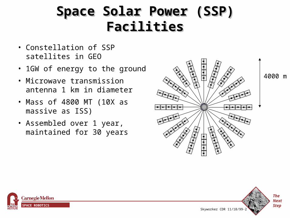
• Constellation of SSP satellites in GEO
• 1GW of energy to the ground
• Microwave transmission antenna 1 km in diameter
• Mass of 4800 MT (10X as massive as ISS)
• Assembled over 1 year, maintained for 30 years
Space Solar Power (SSP) FacilitiesSpace Solar Power (SSP) FacilitiesSpace Solar Power (SSP) FacilitiesSpace Solar Power (SSP) Facilities
4000 m
The Next StepSPACE ROBOTICS INITIATIVE
Skyworker CDR 11/18/99-3
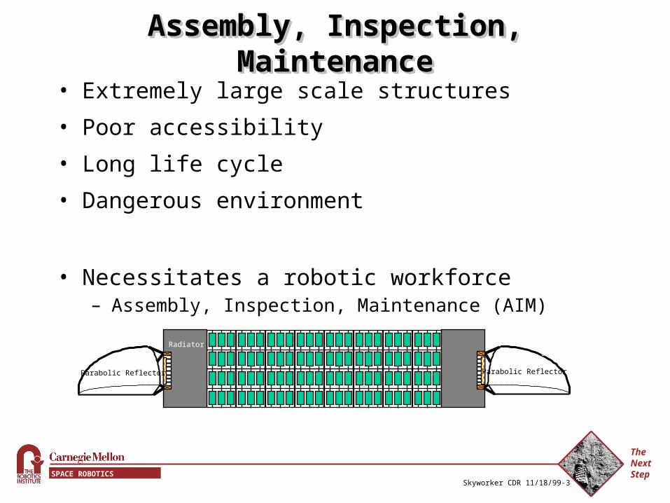
Assembly, Inspection, MaintenanceAssembly, Inspection, MaintenanceAssembly, Inspection, MaintenanceAssembly, Inspection, Maintenance
• Extremely large scale structures
• Poor accessibility
• Long life cycle
• Dangerous environment
• Necessitates a robotic workforce – Assembly, Inspection, Maintenance (AIM)
Radiator
Parabolic Reflector
Radiator
Parabolic Reflector
The Next StepSPACE ROBOTICS INITIATIVE
Skyworker CDR 11/18/99-4
ObjectivesObjectivesObjectivesObjectives
• Demonstrate the viability of using robots for orbital construction
• Prove the validity of using structure walkers for orbital AIM
• Demonstrate SSP AIM relevant tasks using robotics
• Simulate prospective SSP AIM robots and tasks
The Next StepSPACE ROBOTICS INITIATIVE
Skyworker CDR 11/18/99-5
Representative TasksRepresentative TasksRepresentative TasksRepresentative Tasks• Walk, turn, and transition across planes on a truss
structure
• Pick up and place a payload at arbitrary locations and orientations in space
• Carry a payload while walking, turning, and transitioning
• Conduct calibration and inspection tasks
• Connect power and communications cables
• Cooperatively carry massive or large payloads
• Perform tasks that require multiple robot collaboration
The Next StepSPACE ROBOTICS INITIATIVE
Skyworker CDR 11/18/99-6
DemonstrationDemonstrationDemonstrationDemonstration
• Prototype Robot– Pick up and carry a model transmitting element the length of the
truss, turn while carrying, couple the element to the structure– Connect Power Management and Distribution (PMAD) to the
element– Perform a mock calibration
• Simulation– Large scale construction utilizing multiple robots– Coordinated installation of full scale transmitting elements– Demonstrate extended lifetime operations
The Next StepSPACE ROBOTICS INITIATIVE
Skyworker CDR 11/18/99-7
Configuration - Key MetricsConfiguration - Key MetricsConfiguration - Key MetricsConfiguration - Key Metrics
• Continuous Gait
• Forces exerted / Forces experienced
• Workspace
• Control Complexity
• DOF
• Mass
• Cost
• Energy Consumption
The Next StepSPACE ROBOTICS INITIATIVE
Skyworker CDR 11/18/99-8
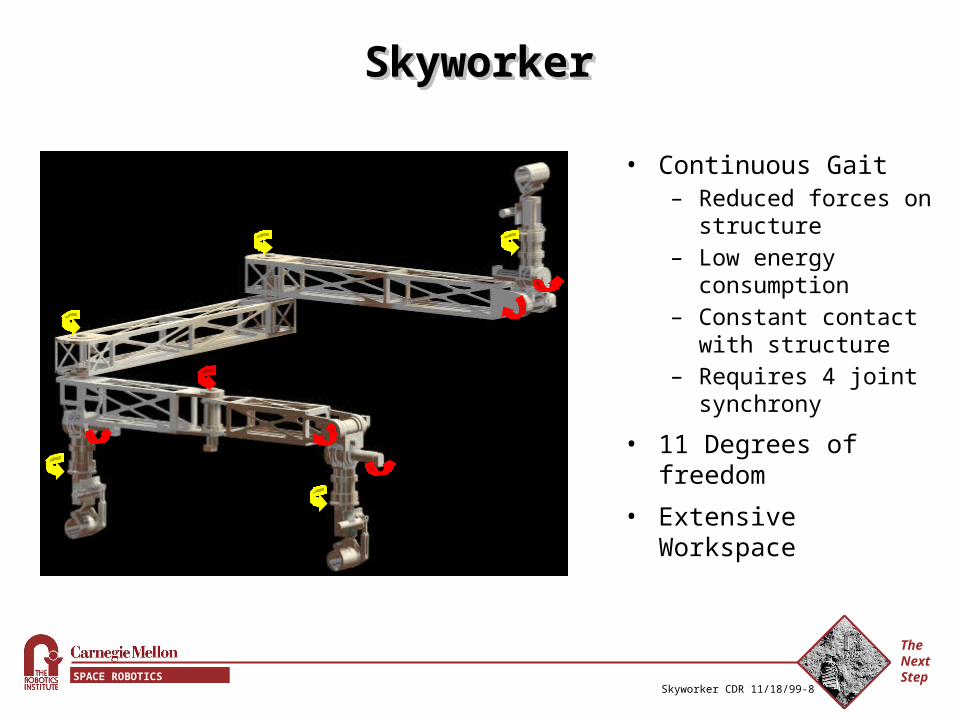
SkyworkerSkyworkerSkyworkerSkyworker
• Continuous Gait– Reduced forces on
structure – Low energy
consumption– Constant contact with
structure– Requires 4 joint
synchrony
• 11 Degrees of freedom
• Extensive Workspace
The Next StepSPACE ROBOTICS INITIATIVE
Skyworker CDR 11/18/99-9
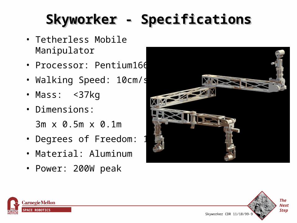
Skyworker - SpecificationsSkyworker - SpecificationsSkyworker - SpecificationsSkyworker - Specifications
• Tetherless Mobile Manipulator
• Processor: Pentium166
• Walking Speed: 10cm/s
• Mass: <37kg
• Dimensions:
3m x 0.5m x 0.1m
• Degrees of Freedom: 11
• Material: Aluminum
• Power: 200W peak
The Next StepSPACE ROBOTICS INITIATIVE
Skyworker CDR 11/18/99-10
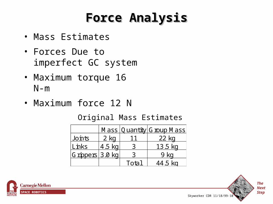
Force AnalysisForce AnalysisForce AnalysisForce Analysis
• Mass Estimates
• Forces Due to imperfect GC system
• Maximum torque 16 N-m
• Maximum force 12 N
Mass Quantity Group MassJoints 2 kg 11 22 kgLinks 4.5 kg 3 13.5 kgGrippers 3.0 kg 3 9 kg
Total 44.5 kg
Original Mass Estimates
The Next StepSPACE ROBOTICS INITIATIVE
Skyworker CDR 11/18/99-11
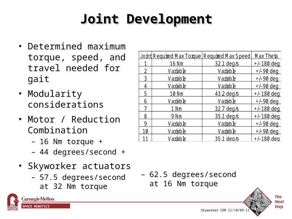
Joint DevelopmentJoint DevelopmentJoint DevelopmentJoint Development
• Determined maximum torque, speed, and travel needed for gait
• Modularity considerations
• Motor / Reduction Combination– 16 Nm torque +– 44 degrees/second +
• Skyworker actuators– 57.5 degrees/second at
32 Nm torque
Joint Required Max Torque Required Max Speed Max Theta1 16 Nm 32.1 deg/s +/- 180 deg2 Variable Variable +/- 90 deg3 Variable Variable +/- 90 deg4 Variable Variable +/- 90 deg5 10 Nm 43.2 deg/s +/- 180 deg6 Variable Variable +/- 90 deg7 1 Nm 32.7 deg/s +/- 180 deg8 9 Nm 35.1 deg/s +/- 180 deg9 Variable Variable +/- 90 deg
10 Variable Variable +/- 90 deg11 Variable 35.1 deg/s +/- 180 deg
– 62.5 degrees/second at 16 Nm torque
The Next StepSPACE ROBOTICS INITIATIVE
Skyworker CDR 11/18/99-12
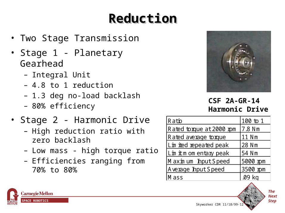
ReductionReductionReductionReduction
• Two Stage Transmission
• Stage 1 - Planetary Gearhead– Integral Unit– 4.8 to 1 reduction– 1.3 deg no-load backlash– 80% efficiency
• Stage 2 - Harmonic Drive– High reduction ratio with zero
backlash – Low mass - high torque ratio– Efficiencies ranging from 70% to
80%
Ratio 100 to 1Rated torque at 2000 rpm 7.8 NmRated average torque 11 NmLimited repeated peak 28 NmLimit momentary peak 54 NmMaximum Input Speed 5000 rpmAverage Input Speed 3500 rpmMass .09 kg
CSF 2A-GR-14 Harmonic Drive
The Next StepSPACE ROBOTICS INITIATIVE
Skyworker CDR 11/18/99-13
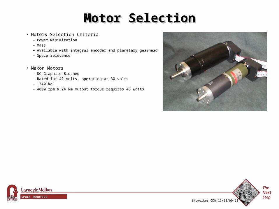
Motor SelectionMotor SelectionMotor SelectionMotor Selection• Motors Selection Criteria
– Power Minimization– Mass – Available with integral encoder and planetary gearhead– Space relevance
• Maxon Motors– DC Graphite Brushed– Rated for 42 volts, operating at 30 volts– .340 kg– 4800 rpm & 24 Nm output torque requires 48 watts
The Next StepSPACE ROBOTICS INITIATIVE
Skyworker CDR 11/18/99-14
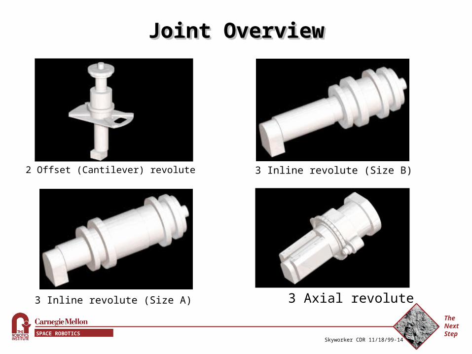
Joint OverviewJoint OverviewJoint OverviewJoint Overview
3 Inline revolute (Size A)
2 Offset (Cantilever) revolute 3 Inline revolute (Size B)
3 Axial revolute
The Next StepSPACE ROBOTICS INITIATIVE
Skyworker CDR 11/18/99-15
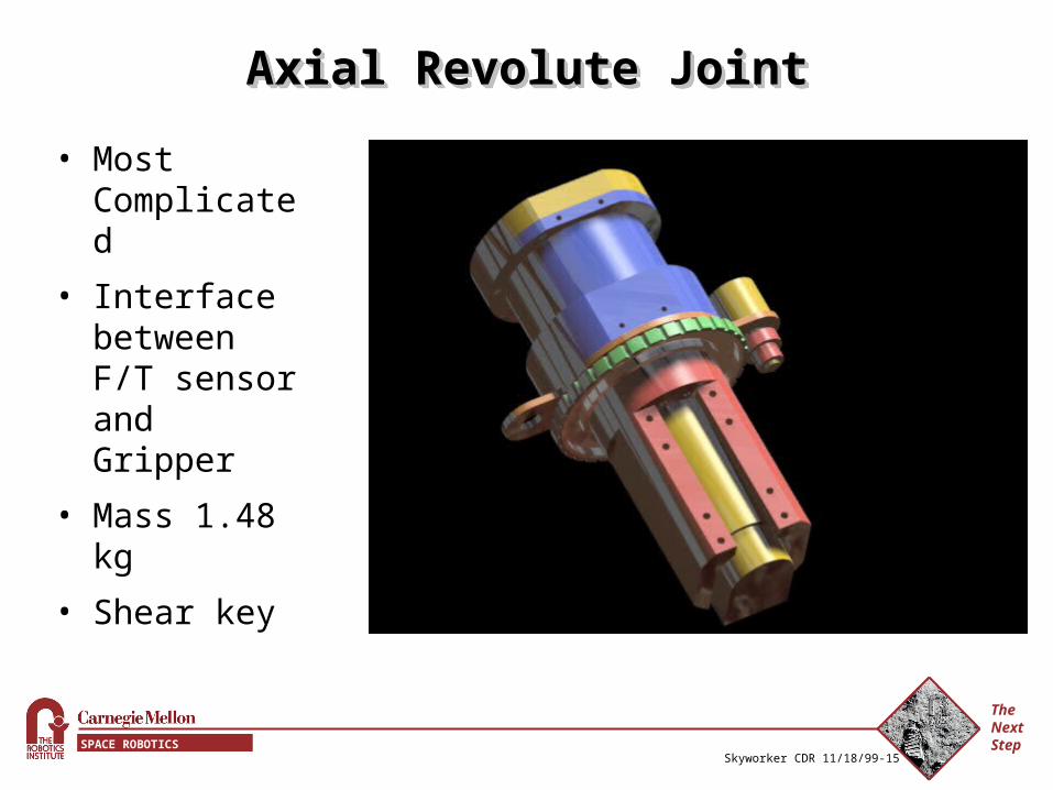
Axial Revolute JointAxial Revolute JointAxial Revolute JointAxial Revolute Joint
• Most Complicated
• Interface between F/T sensor and Gripper
• Mass 1.48 kg
• Shear key
The Next StepSPACE ROBOTICS INITIATIVE
Skyworker CDR 11/18/99-16
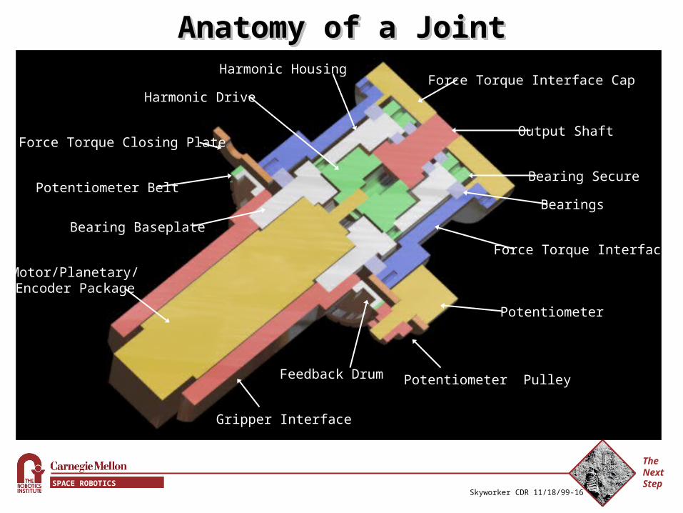
Anatomy of a JointAnatomy of a JointAnatomy of a JointAnatomy of a Joint
Force Torque Interface Cap
Force Torque Interface
Bearing Secure
Bearings
Output Shaft
Harmonic Housing
Harmonic Drive
Potentiometer Belt
Feedback Drum
Bearing Baseplate
Gripper Interface
Force Torque Closing Plate
Potentiometer Pulley
Potentiometer
Motor/Planetary/Encoder Package
The Next StepSPACE ROBOTICS INITIATIVE
Skyworker CDR 11/18/99-17
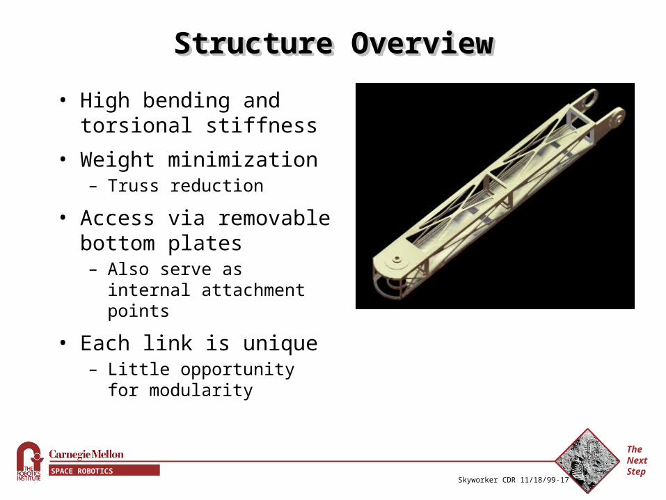
Structure OverviewStructure OverviewStructure OverviewStructure Overview
• High bending and torsional stiffness
• Weight minimization– Truss reduction
• Access via removable bottom plates– Also serve as internal
attachment points
• Each link is unique– Little opportunity for
modularity
The Next StepSPACE ROBOTICS INITIATIVE
Skyworker CDR 11/18/99-18
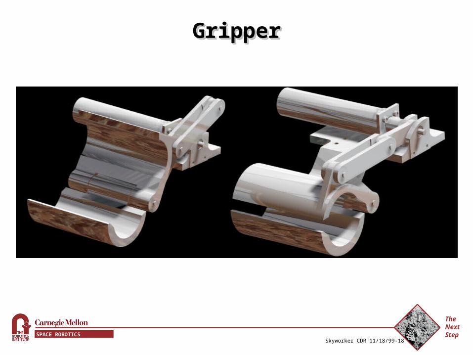
GripperGripperGripperGripper
The Next StepSPACE ROBOTICS INITIATIVE
Skyworker CDR 11/18/99-19
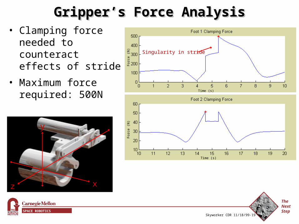
Gripper’s Force AnalysisGripper’s Force AnalysisGripper’s Force AnalysisGripper’s Force Analysis• Clamping force
needed to counteract effects of stride
• Maximum force required: 500N
x
y
z
Time (s)
Time (s)
For
ce (
N)
For
ce (
N) Singularity in stride
The Next StepSPACE ROBOTICS INITIATIVE
Skyworker CDR 11/18/99-20
ConceptConceptConceptConcept
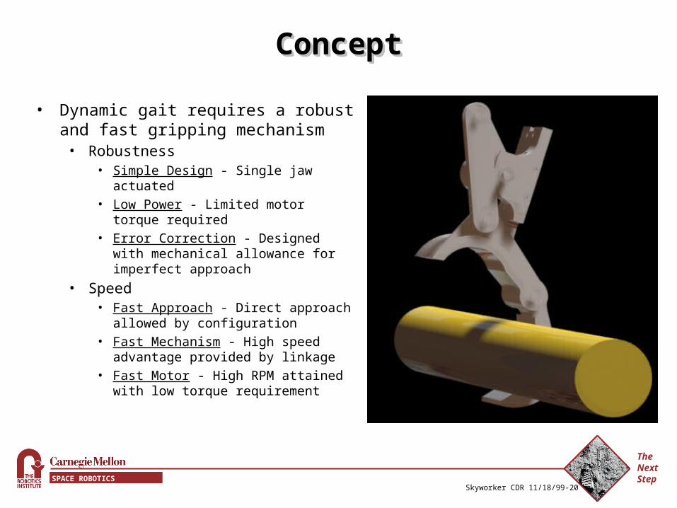
• Dynamic gait requires a robust and fast gripping mechanism
• Robustness• Simple Design - Single jaw actuated• Low Power - Limited motor torque
required• Error Correction - Designed with
mechanical allowance for imperfect approach
• Speed• Fast Approach - Direct approach
allowed by configuration• Fast Mechanism - High speed
advantage provided by linkage• Fast Motor - High RPM attained with low
torque requirement
The Next StepSPACE ROBOTICS INITIATIVE
Skyworker CDR 11/18/99-21
MechanismMechanismMechanismMechanism
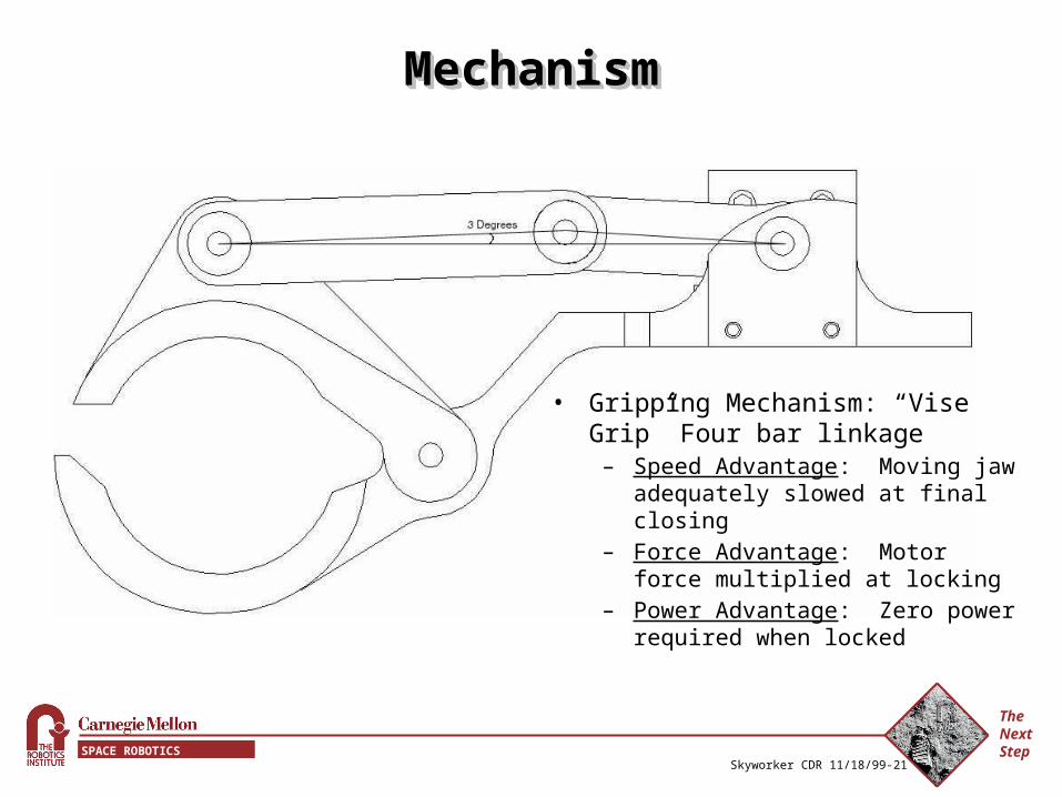
• Gripping Mechanism: “Vise Grip” Four bar linkage
– Speed Advantage: Moving jaw adequately slowed at final closing
– Force Advantage: Motor force multiplied at locking
– Power Advantage: Zero power required when locked
The Next StepSPACE ROBOTICS INITIATIVE
Skyworker CDR 11/18/99-22
CoatingCoatingCoatingCoating
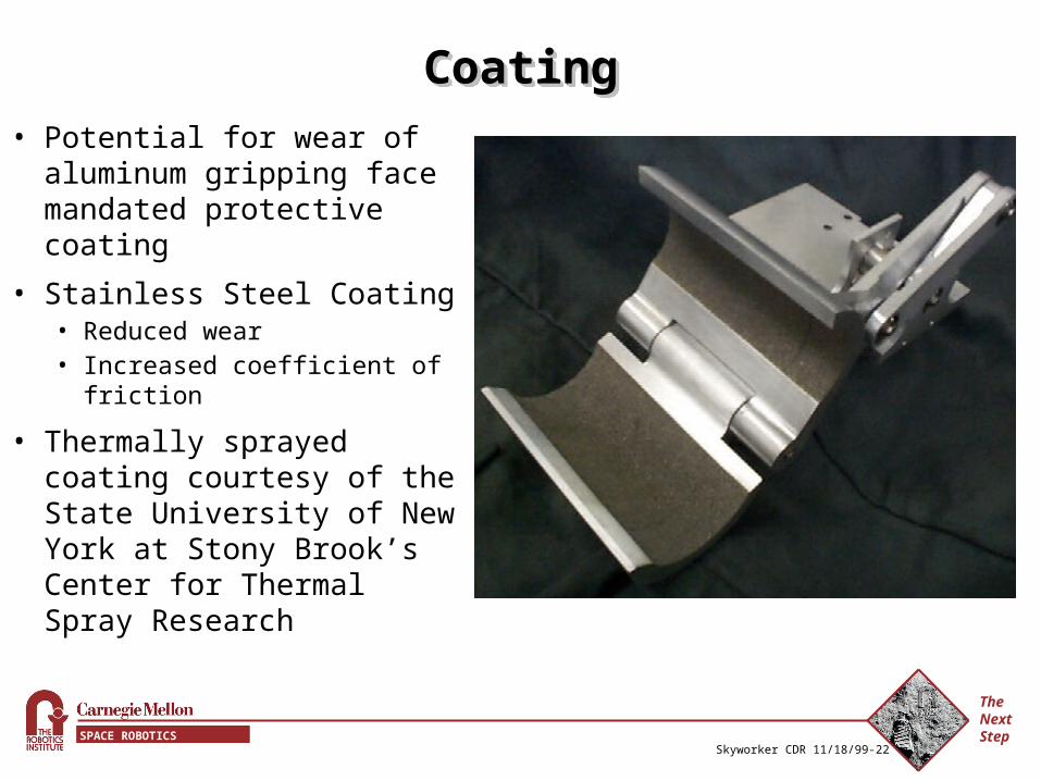
• Potential for wear of aluminum gripping face mandated protective coating
• Stainless Steel Coating• Reduced wear• Increased coefficient of
friction
• Thermally sprayed coating courtesy of the State University of New York at Stony Brook’s Center for Thermal Spray Research
The Next StepSPACE ROBOTICS INITIATIVE
Skyworker CDR 11/18/99-23
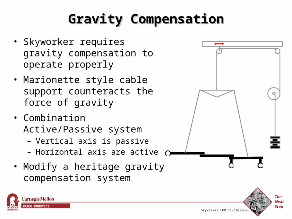
Gravity CompensationGravity CompensationGravity CompensationGravity Compensation
• Skyworker requires gravity compensation to operate properly
• Marionette style cable support counteracts the force of gravity
• Combination Active/Passive system– Vertical axis is passive– Horizontal axis are active
• Modify a heritage gravity compensation system
The Next StepSPACE ROBOTICS INITIATIVE
Skyworker CDR 11/18/99-24
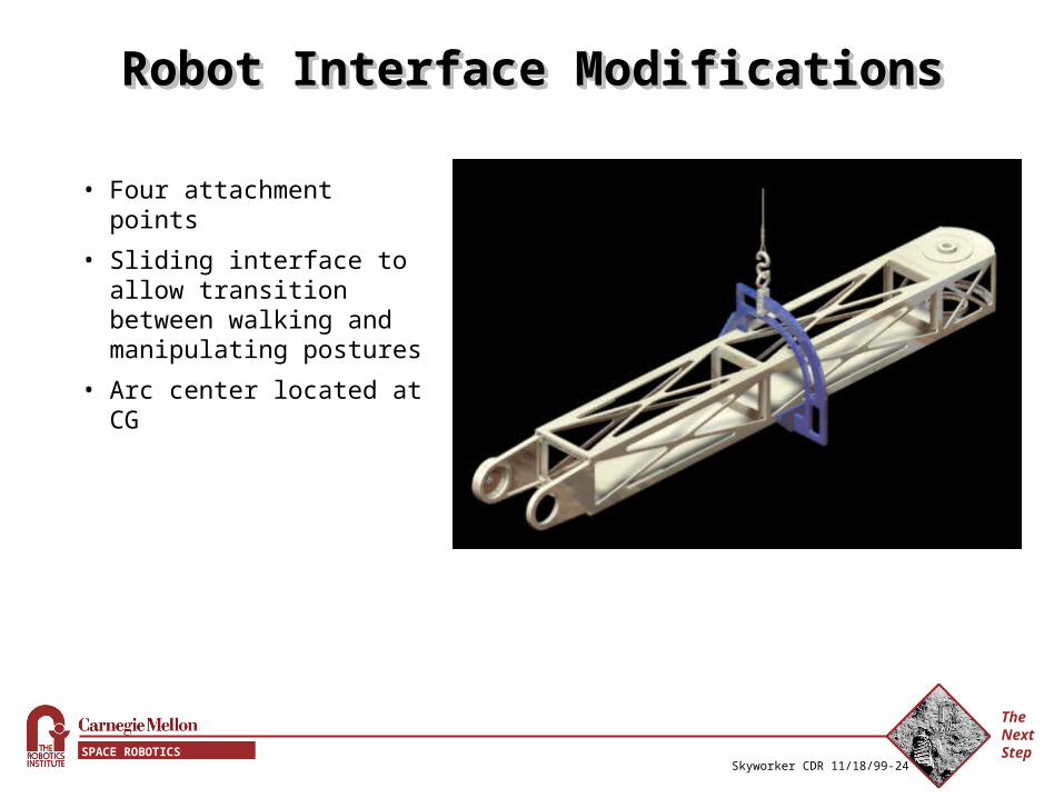
Robot Interface ModificationsRobot Interface ModificationsRobot Interface ModificationsRobot Interface Modifications
• Four attachment points
• Sliding interface to allow transition between walking and manipulating postures
• Arc center located at CG
The Next StepSPACE ROBOTICS INITIATIVE
Skyworker CDR 11/18/99-25
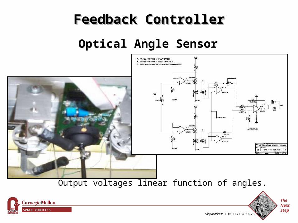
Feedback ControllerFeedback ControllerFeedback ControllerFeedback Controller
Optical Angle Sensor
Picture of shuttle withangle sensor board
(to be taken w/ digital camera)
Output voltages linear function of angles.
The Next StepSPACE ROBOTICS INITIATIVE
Skyworker CDR 11/18/99-26
Feedback ControllerFeedback ControllerFeedback ControllerFeedback Controller
Control Issues
• Gantry pendulum is a fourth order system
• Model as a second order system– Second order model sufficiently accurate over a small range of
inputs.– Skyworker will only move over a small range of velocities.– Tune PID controller for good responses over these inputs.– Hack: Zero integral term with change of direction (faster
response)
The Next StepSPACE ROBOTICS INITIATIVE
Skyworker CDR 11/18/99-27
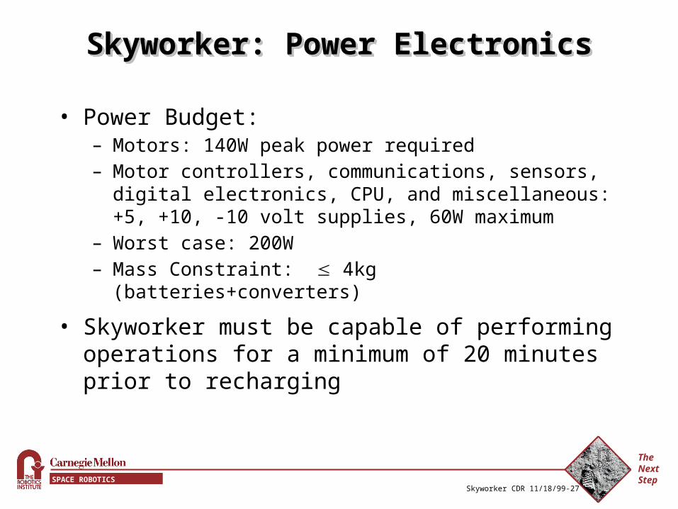
Skyworker: Power ElectronicsSkyworker: Power ElectronicsSkyworker: Power ElectronicsSkyworker: Power Electronics
• Power Budget:– Motors: 140W peak power required– Motor controllers, communications, sensors, digital
electronics, CPU, and miscellaneous: +5, +10, -10 volt supplies, 60W maximum
– Worst case: 200W – Mass Constraint: 4kg (batteries+converters)
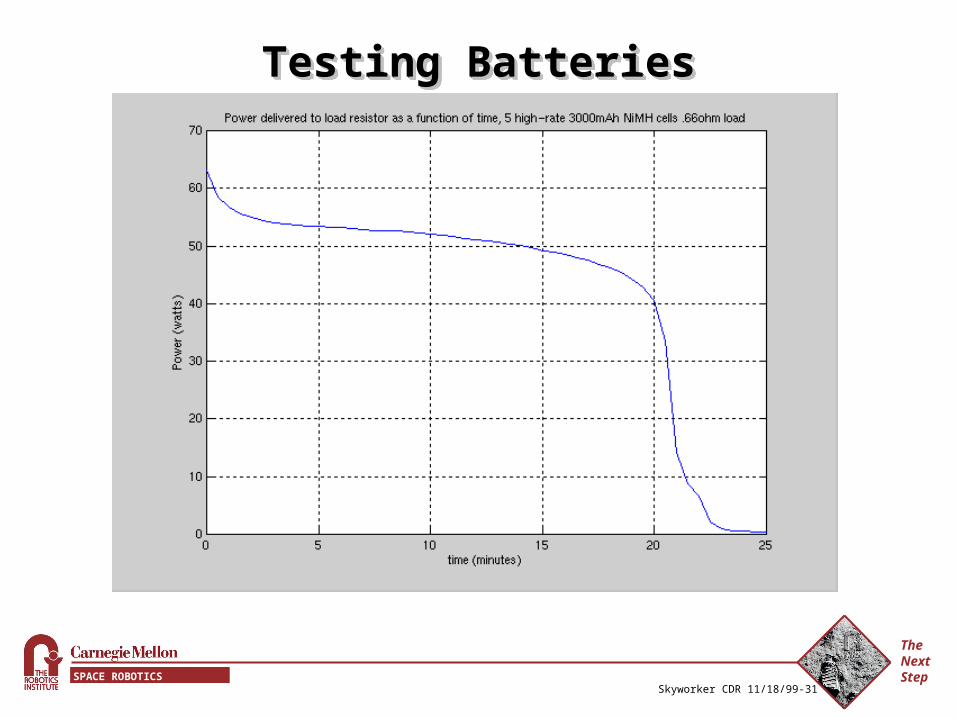
• Skyworker must be capable of performing operations for a minimum of 20 minutes prior to recharging
The Next StepSPACE ROBOTICS INITIATIVE
Skyworker CDR 11/18/99-28
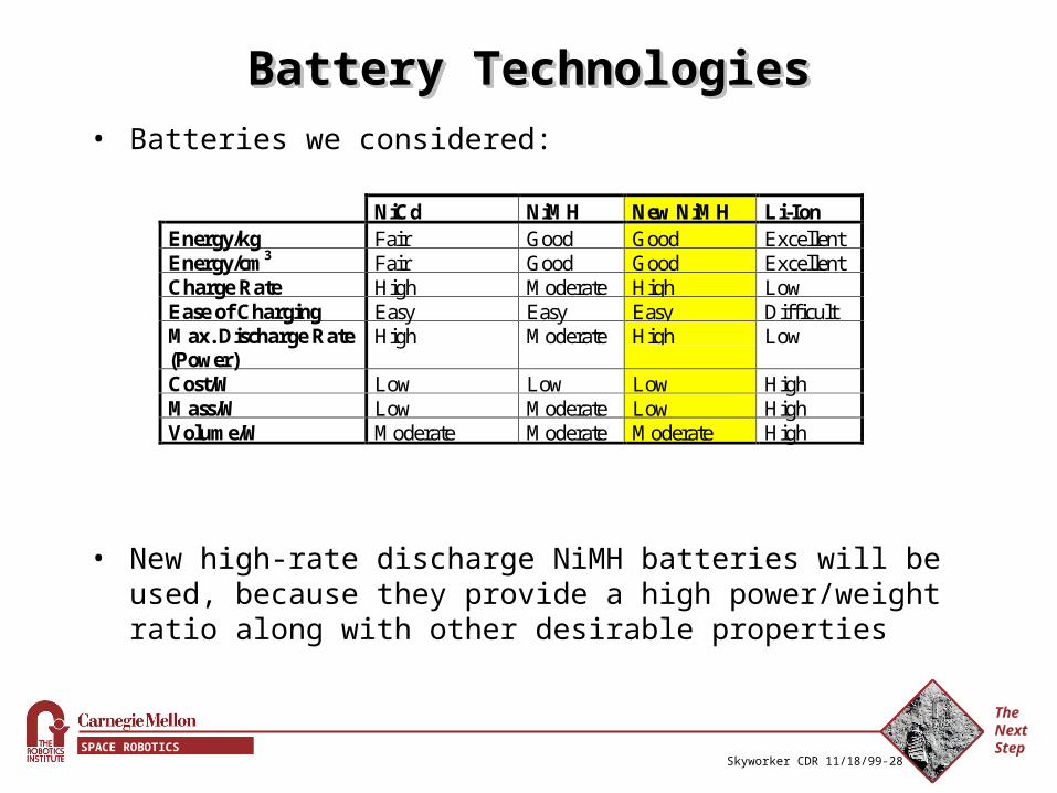
Battery TechnologiesBattery TechnologiesBattery TechnologiesBattery Technologies• Batteries we considered:
• New high-rate discharge NiMH batteries will be used, because they provide a high power/weight ratio along with other desirable properties
NiCd NiMH New NiMH Li-IonEnergy/kg Fair Good Good ExcellentEnergy/cm3 Fair Good Good ExcellentCharge Rate High Moderate High LowEase of Charging Easy Easy Easy DifficultMax. Discharge Rate(Power)
High Moderate High Low
Cost/W Low Low Low HighMass/W Low Moderate Low HighVolume/W Moderate Moderate Moderate High
The Next StepSPACE ROBOTICS INITIATIVE
Skyworker CDR 11/18/99-29
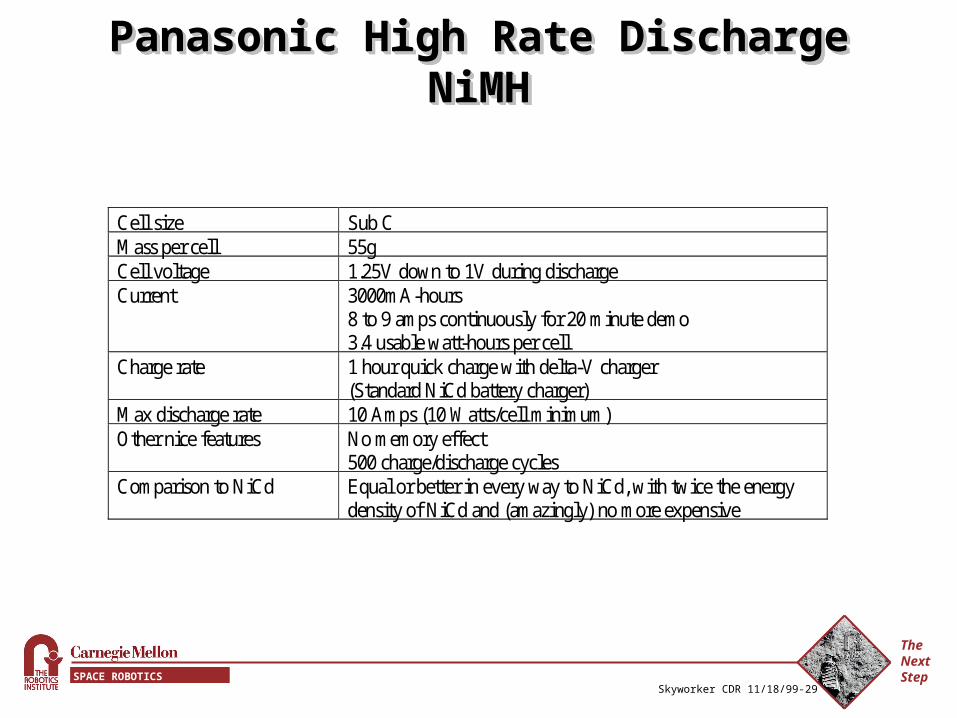
Panasonic High Rate Discharge NiMHPanasonic High Rate Discharge NiMHPanasonic High Rate Discharge NiMHPanasonic High Rate Discharge NiMH
Cell size Sub C Mass per cell 55g Cell voltage 1.25V down to 1V during discharge Current 3000mA-hours
8 to 9 amps continuously for 20 minute demo 3.4 usable watt-hours per cell
Charge rate 1 hour quick charge with delta-V charger (Standard NiCd battery charger)
Max discharge rate 10 Amps (10 Watts/cell minimum) Other nice features No memory effect
500 charge/discharge cycles Comparison to NiCd Equal or better in every way to NiCd, with twice the energy
density of NiCd and (amazingly) no more expensive
The Next StepSPACE ROBOTICS INITIATIVE
Skyworker CDR 11/18/99-30
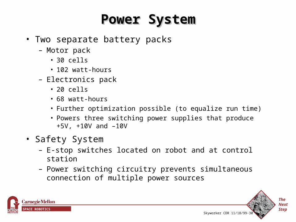
Power SystemPower SystemPower SystemPower System
• Two separate battery packs– Motor pack
• 30 cells• 102 watt-hours
– Electronics pack • 20 cells• 68 watt-hours• Further optimization possible (to equalize run time)• Powers three switching power supplies that produce +5V, +10V
and –10V
• Safety System– E-stop switches located on robot and at control station– Power switching circuitry prevents simultaneous connection of
multiple power sources
The Next StepSPACE ROBOTICS INITIATIVE
Skyworker CDR 11/18/99-31
Testing BatteriesTesting BatteriesTesting BatteriesTesting Batteries
The Next StepSPACE ROBOTICS INITIATIVE
Skyworker CDR 11/18/99-32
Battery and Tethered OperationBattery and Tethered OperationBattery and Tethered OperationBattery and Tethered Operation
• Charging– Using external delta-V chargers to charge batteries without
removing them from Skyworker
• Battery Monitoring System– Battery voltage monitoring circuitry will let Skyworker know
that it’s batteries are nearly drained
• When Skyworker’s batteries are recharging, it can run off of a tether that supplies 36V and 24V to Skyworker’s motors and voltage regulators.
The Next StepSPACE ROBOTICS INITIATIVE
Skyworker CDR 11/18/99-33
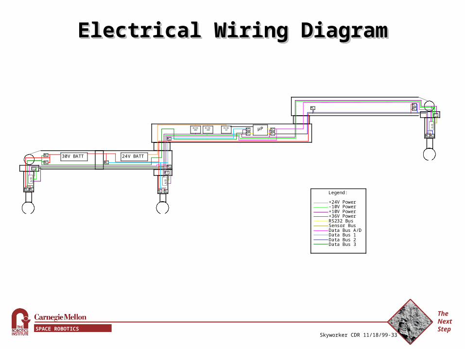
Electrical Wiring DiagramElectrical Wiring DiagramElectrical Wiring DiagramElectrical Wiring Diagram
A/D
µP
A/D
MC MC
MC
MC MC
MC
MC
MC MC
MC
MC
MC
DC/DC 5V
DC/DC 10V
DC/DC -10V
A/D
MC MC
SC SC SC
SC
30V BATT 24V BATT
FT FT
FT
Legend:
+24V Power -10V Power +10V Power +36V Power RS232 Bus Sensor Bus Data Bus A/D Data Bus 1 Data Bus 2 Data Bus 3
The Next StepSPACE ROBOTICS INITIATIVE
Skyworker CDR 11/18/99-34
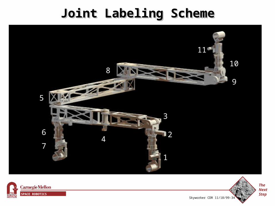
Joint Labeling SchemeJoint Labeling SchemeJoint Labeling SchemeJoint Labeling Scheme
1
2
3
4
5
6
7
8
9
10
11