Embed Size (px)
Citation preview
The Need for Speed: Computations for EUV Lithography
HJL Lithography 26 February 2019eBeam Initiative SPIE 2019

HJL Lithography 1
Gwyn and Silverman,
“EUV Lithography
Transition from Research
to Commercialization,”
Photomask Japan, 2003
EUV lithography implemented at different node than originally conceived
Minimum pitch = 160 nm
eBeam Initiative SPIE 2019
HJL Lithography 2
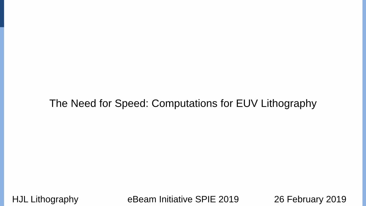
Horizontal-vertical bias due to oblique illumination
Erdmann,et al.
"Characterization and mitigation of 3D mask
effects in extreme ultraviolet lithography."
Advanced Optical Technologies 6, no. 3-4 (2017)
eBeam Initiative SPIE 2019

HJL Lithography eBeam Initiative SPIE 2019 3
Biases in-between
• Ring-field optics have
long been used in
scanning lithography
• Reduced aberrations
Exposure field
Exposure slit
~19o

HJL Lithography 4
Pei-Yang Yan,
“Understanding Bossung Curve
Asymmetry and Focus Shift
Effect in EUV Lithography,”
BACUS Symposium on
Photomask Technology,
2001
Mask 3D effects were recognized early: Pitch dependence for focus
eBeam Initiative SPIE 2019

HJL Lithography 5
S. Raghunathan, et al., “Characterization of
Telecentricity Errors in High-Numerical-Aperture
Extreme Ultraviolet Mask Images,” 3-beams (2014)
Fo
cu
s a
xis
high
intensity
low
intensity
Lateral position (mm)
Pattern placement errors through focus
L. Van Look, et al.,“Mask 3D Effect Mitigation by Source
Optimization and Assist Feature Placement”
(2016)
This is new: Overlay needs to be considered
when employing process window-aware OPC!
eBeam Initiative SPIE 2019

HJL Lithography 6
CD versus focus for 2-bar
structures, 32 nm pitch:
T. Last, et al. “Illumination pupil optimization in
0.33-NA extreme ultraviolet lithography by
intensity balancing for semi-isolated dark field
two-bar M1 building blocks,” JM3 (2016)
Mask 3D effects drive need for complex illumination
eBeam Initiative SPIE 2019

HJL Lithography 7
Image blurring due to mask 3D effects
Jo Finders, 2017 EUVL
Symposium
extended sources result
in blurred images
Images from different
source points are displaced
laterally
eBeam Initiative SPIE 2019

HJL Lithography 8eBeam Initiative SPIE 2019
21 nm hp image blurring example

HJL Lithography 9
NILS = 1.61
LER = 3.6 nm
NILS = 1.57
LER = 3.7 nm
NILS = 2.05
LER = 2.6 nm
"Application of EUV resolution
enhancement techniques (RET)
to optimize and extend single
exposure bi-directional patterning
for 7nm and beyond logic
designs"
Ryoung-Han Kim et. al.,
SPIE Advanced Lithography
Symposium (2016)
Quadrupole
illumination
32-nm pitch
lines/spaces
SMO standard
solution
SMO NILS
optimized
Need to maintain normalized image log-slope (NILS) to address LER
eBeam Initiative SPIE 2019

HJL Lithography eBeam Initiative SPIE 2019 10
Freeform illumination is now available for EUV lithography

HJL Lithography 11eBeam Initiative SPIE 2019
Aberrations are significant for EUV lithography
Winfried Kaiser, Semicon Korea, 2018
0.2 nm = 15 ml

HJL Lithography 12
0.8
1
1.2
1.4
1.6
36 40 52 150
Physicalresistmodel
4 nm blur
resist blurs image
resist sharpens image
Adapted from S. Hansen, JM3
• OPC models need to
contend with pitch-
dependent resist-blur
Complex resist physics
Pitch (nm)
Image log-slope
Resist-edge log-slope
eBeam Initiative SPIE 2019
18 nm trenches

HJL Lithography 13
Deniz Civay, et al.,
“Subresolution assist features in
extreme ultraviolet lithography,”
JM3 (2015)
Mask SEM
image
Design
layout
Developed resist
on-wafer SEM image
Sub-resolution assist features (SRAFs) for EUV lithography
eBeam Initiative SPIE 2019

HJL Lithography 14
Pei-Yang Yan,
“Understanding Bossung Curve
Asymmetry and Focus Shift
Effect in EUV Lithography,”
BACUS Symposium on
Photomask Technology,
2001
Application of SRAFs significantly reduces range of focus shifts
eBeam Initiative SPIE 2019

HJL Lithography 15
Application of SRAFs significantly reduces range of focus shifts
eBeam Initiative SPIE 2019
Pei-Yang Yan,
“Understanding Bossung Curve
Asymmetry and Focus Shift
Effect in EUV Lithography,”
BACUS Symposium on
Photomask Technology,
2001
~40% reduction in
best focus variation

HJL Lithography 16
The future is curvilinear
K. Hooker, A. Kazarian, X. Zhou, J. Tuttle, G. Xiao, Y. Zhang, and K. Lucas
"New methodologies for lower-K1 EUV OPC and RET optimization."
Proc. SPIE Vol. 10143 (2017)
70 nm X-pitch,
60 nm Y-pitch
eBeam Initiative SPIE 2019

HJL Lithography 17
Many geometries in today’s chips creates big computational problem
• AMD’s Ryzen 7
microprocessor has
4.8B transistors
eBeam Initiative SPIE 2019

HJL Lithography 18
Ring-field EUV optics kills hierarchy – another computation complexity
Reticle field
Exposure field
Exposure slit
eBeam Initiative SPIE 2019
~19o

HJL Lithography 19
Flare also breaks hierarchy
eBeam Initiative SPIE 2019

HJL Lithography 20
Current situation
• The physics of EUV lithography necessitates computations more complex than those
encountered in optical lithography
• Significant mask 3D effects
• Multiple manifestations
• Plane of best focus dependent on pitch and position within arrays
• Image blur
• Pattern placement shifts
• Variations across the slit
• Flare and aberrations
• Complex resist behavior
• Support needed for curvilinear features
• Large chip sizes at the leading edge creates need for fast computational capabilities
eBeam Initiative SPIE 2019

HJL Lithography 21
Lithography simulations are amenable to parallel computations
Mask Image intensity
B
A
P. De Bisschop,
JM3, 2018
eBeam Initiative SPIE 2019
HJL Lithography 22
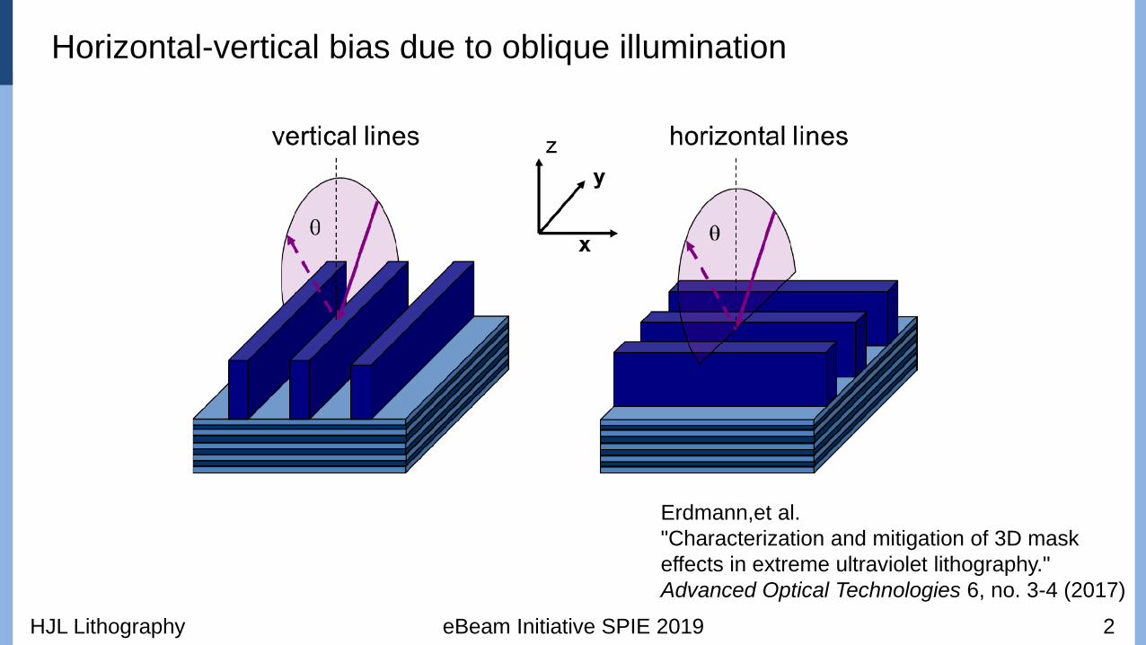
Lithography simulations are amenable to parallel computations
• Use of multiple servers with multiple-core
processors are used routinely for optical
lithography
• Example
• 64 core microprocessors
• 100 servers
• 6400 cores
eBeam Initiative SPIE 2019
Lithographic calculations extensively involve FFTs
• Greater computational capability
will be needed for EUV lithography
• OPC computations can still
take 24 hours or more for
optical lithography
• Inverse lithography calculations can
take so long that they are often
applied only to select patterns

HJL Lithography 23
Parallel computations: New paradigm with GPUs
Nvidia Volta GPU:
5120 cores
eBeam Initiative SPIE 2019

HJL Lithography 24
Curvilinear shapes: practical with multi-beam mask writing
Patterns created with Nuflare MBM-1000IMS MBMW-101
eBeam Initiative SPIE 2019
Return to raster scanning

HJL Lithography 25
Summary
• Future OPC/RET for EUV lithography will necessarily be very complex
• Mask 3D effects
• Increases need for SRAFs
• Resist physics
• Large chips manufactured with leading-edge lithography necessitate powerful computational
and mask-making capabilities
• Fortunately, the infrastructure is becoming available to support solutions
• GPU’s can provide a path to a much higher degree of parallel computing
• EUV exposure tools now have freeform pupil shaping capabilities
• Multiple-beam mask writers enable curvilinear patterns
eBeam Initiative SPIE 2019


![THE SMITH GROUP AND THE CRITICAL GROUP OF THE … · graphs. A particular class that has proved amenable to computations is the class of strongly regular graphs (e.g. [4]). In this](https://img.dokumen.tips/doc/110x75/5e321e91cbeae64ff23a8225/the-smith-group-and-the-critical-group-of-the-graphs-a-particular-class-that-has.jpg)