Embed Size (px)
Citation preview

Journal of Scientific & Industrial Research
Vol. 80, September 2021, pp. 766-776
The Modular Nonoverlapping Grasp Workspaces and Dynamics for the Grippers
using the Micro and Macro C-Manifold Design
Haydar Sahin
Department of the Mechatronics Engineering, Istanbul Gedik University, Istanbul, 34 987, Turkey
Received 02 March 2021; revised 11 August 2021; accepted 13 August 2021
The toolbox for the gripper workspace analyses using Lie algebra is developed for shape variables (α1-4 − θ1,2) of the
skew revolute joints. The unique methodology for grippers comprises to enable the variety of manifold analyses for
kinematics and dynamics using symbolic mathematics. The Controllable Instantaneous Screw Axes (C-ISA) are defined
through the shape variables considering the twists of the skew revolute joints se(3). The derivation and analyses of the
kinematics and dynamics equations are made possible using the developed methodology with the defined constraints for
gripper mechanisms. The Modular Gripper with Lie Algebra Toolbox (M-GLAT) is developed for the defined constraints of
the angle between C-ISA 1 and C-ISA 2. The novelty subject of this article is the development of the M-GLAT method for
derivation of the constraint based workspaces with the shape variables (α1-4 − θ1,2) in the field of the spatial 2-RR gripper
mechanisms. The gripper dynamics with constraint based workspaces of the skew revolute joints are developed for varied
configurations of α1-4 with ICs of θ1,2. The modular rule-based workspaces are analyzed for the shape variables of the
(α1-4 − θ1,2) with the task spaces. This design produces dexterity with the modular grasp workspaces for the gripper fingers
with skew revolute joints. One can select a combination of C-manifolds of (π/20, π/40, π/80) for the requirement of the
nonoverlapping workspaces of the gripper finger designs as the grasp surfaces to control. The modular nonoverlapping
workspace design with dynamics herein is based on the shape variables (α1-4 − θ1,2) using skew revolute joint which produce
the high dexterity for the grasping capability of the grippers. The modular micro and macro C-manifold designs obtained the
constraint based workspace algorithms of the 2-RR gripper which is expandable into the higher modular revolute joints of
the n-R for the grippers. The n-R modular expandable grippers are increasing the precision and power grasping capability.
Keywords: Lie algebra, Lie group theory, Shape variables of skew revolute, Spatial robot kinematics and dynamics, Task space
Introduction
The configuration-dependent modular design
considers spatial controllable instantaneous screw axis
(C-ISA) orientation as a manifold of 2-RR modular
robot parameters for specified applications. The novel
modular design concept herein is developed using the
2-RR common mechanisms for the grippers of the
service and industrial robots.1 The two classifications
herein of the 2-RR modular grippers for robots are
micro and macro configuration-dependent modular
designs analyzed in-depth in this research article with
kinematic results. Additionally, the challenging era of
symbolic mathematics of modern robot dynamics is
emerging to derive the Equation of Motion (EOM)
using the integrated Lie group theory. The Lie group
theory analyzed the robot dynamics and kinematics
thoroughly.2–6
The skew revolute joints for the serial
robots7,8
are applicable herein for the gripper
mechanisms with the skew axis of the C-ISA.
Gripper poses for the precision or power grasp herein
can be modified using the algorithms developed from
the M-GLAT.
The skew axis is a part of the mechanism common
in the wrist and gripper designs. The decoupling for
the wrist design is studied experimentally without
considering the coupled dynamics and the kinematic
equations.9–11
Wrist joints have skew revolute axes.
Additionally, the research in ISA has been specifying
the motion pattern of the mechanism for the skew axis
of rotation.12
The 2-screw system, examined in this
article, of the 2-RR robots are classified into special
groups for kinematics analysis and control.13,14
The
advantage of the revolute joint with the skew axis is
its high maintainability with the developed models for
multibody dynamics in the literature.15
The modular
workspaces herewith the dynamics for the modular
grippers are developed beside the results of
workspaces and dynamics in this research article.
A toolbox with various constraints definable is an
asset for a modular gripper design. Thus, the
workspace of the gripper herein was analyzed using
—————— *Author for Correspondence
E-mail: [email protected]

SAHIN: MICRO -MACRO MODULAR NONOVERLAPPING GRASP WORKSPACES
767
the constraints of the angle between two C-ISA with a
developed toolbox. The angle between the C-ISA 1
and C-ISA 2 is a constraint for the workspace design
pivotal to define the modular grasp capability of the
gripper. Therefore, the angle between the C-ISA 1
and C-ISA 2 is chosen as a constraint for the micro
and macro configurations of the gripper herein. Thus,
the purpose of this research article is to develop a
multi-functional tool wherein the constraint-based
kinematics and dynamics equations can be derived for
the skew revolute joints of the n-R gripper
mechanism. One would need the skew revolute joint
to grasp complex objects in hand with high dexterity.
Thus, the determination of the workspace for grasping
surface is required for skew revolute mechanisms
considering dynamics. Modular Gripper with Lie
Algebra Toolbox (M-GLAT) is developed within the
defined constraints of the angle between C-ISA 1 and
2. Additionally, various constraints herewith were
defined using the M-GLAT for n-R gripper
mechanisms such as 3-R. The novel modular micro
and macro gripper workspaces via shape variables of
(α1-4 − θ1,2) are defined using the M-GLAT developed
herein.
The configuration spaces (C-space) for the skew
revolute joint mechanisms are specified based on the
requested task spaces for path planning. The
algorithms developed are for the obstacle avoidance
of the robots based on this path planning strategy. The
defined C-space is a position vector concerning
spatial coordinate q ∈ Q1 of SE (3).5,16
The ℝ3 term
defines the position of the end effector, while the SO
(3) defines the orientation of the C-space. The
transformation matrix of g1j_2 acting as Q1 is a group
variable of the SE (3) matrix for the position and
orientation.5,16
The C-space maps are the unification
of the requested C-spaces for motion planning of the
obstacle avoidance.
The configuration defines all the possible positions
of the mechanisms with skew revolute joints. The
group variable of g in SE (3) can be modified in Lie
algebra as 𝔤−1𝔤 in SE (3) the velocity. S is the shape
space containing the shape variables of the
(α1-4 − θ1,2). The configuration of the modular
structure defines the (Q2 = G×S) for the serial
robots.17
The configuration of the robots is congruent
with the matched shape variables S of the group
variables G. The set cluster of the group variables
with the shape variables of S can structure all the
possible positions for the mechanism as configuration
Q2.17
The workspace defines the end effector
configurations, which can be reached.4,16
Task space
is the space of a specific task of which the motion of
the robot’s end-effector obtains during this task.4,16
The configuration manifold means all the possible
positions for the defined manifold of the locally
Euclidean space. The configuration manifold
(C-manifold) is represented by the (Q3= SE(3) × S1 × S
1
=GM) as the positioning in the SE(3) using the base
manifold S1
× S1.(16,17)
Since the S1
× S1
manifold
structures the revolute rotational joints of the locally
Euclidean space, the result of the C-manifold of Q3 as
a result within the SE(3) group is the locally
Euclidean space system of another manifold. The
group structure of SE(3) assigns to the C-manifold of
the Q3. The assignment achieves the matching the
group of the displacements with the C-space of Q1.18
While the base S1×S
1 defines the manifold as M,
the SE(3) defines the Lie group as G.19
The shape
term considers the C-manifold that is isomorphic to
the shape of the 2-RR modular robots. Additionally,
the article in this study here modified the shape space
of the S1×S
1 for the potential shape variables of the
α1-4, θ1, and θ2, having configured the modular
C-manifolds of the skew revolute joints. The
M-GLAT method can manipulate to develop
algorithms of the systematic trajectories reliant on the
differential geometry as defined in the literature19
for
modular C-manifold of 2-RR grippers. The M-GLAT
algorithm, structured as a novel toolbox, is
programmed in Maxima.
Manifold, a space qualification definition in
topology, acts with a criterion of behaving locally in
Euclidean space.20
The topologies of the line and
circle correspond to the prismatic and revolute joints
in terms of motion types, respectively. The manifolds
of circle S1 or line structures the body coordinate
systems, which have a property of topological space
defined as locally.20
The reduced shape variables,
shape control, and shape variables are the terminology
of the mechanisms for kinematics and the dynamics
of manifolds in literature.16,21
The specified shape
variables of the 𝜃1,2 and 𝛼1−4 are substituted with the
constant values of the manifold’s shape structure for
kinematic analysis in this article. Meanwhile, the rest
called the reduced shape variables changed in
arranged range for workspace and trajectory analyses
of the path planning.
The modular structure analysis succeeds with the
results for the mechanisms of the C-ISA 1 and 2

J SCI IND RES VOL 80 SEPTEMBER 2021 768
C-manifolds for the (S2
× S2, S
1 × S
2, S
1 × S
1, S
2 × S
1)
using the shape variables of 𝜃1−2 ,𝛼1−4. The common
mechanism of the micro modular C-manifold enables
the design of the macro modular structure with a
C-ISA C-manifold of the kinematic equations derived
using the M-GLAT method. The angle in between the
skew axes specifies the common mechanisms
modularly for the defined C-manifolds.
The purpose of the C-ISA C-manifold of the skew
revolute joints for the 2-RR modular robotic gripper
with this research article is to generate novel various
kinematic geometries as workspaces using the six
shape variables of the 𝜃1,2 and 𝛼1−4 for the shape
spaces of S1×S
1 and possibly S
2. Upon designing the
micro modular C-manifolds, the angle between the
skew axes for invented configurations shapes the
modularity within the common mechanisms of micro
modular C-manifolds. This angle describes the
relative integration of each unique C-ISA structure for
2-RR modular robot gripper designs, as shown in
Fig. 1 with θ1-2 and α1-4. The l1 is the length of the
rigid body as link 1. Moreover, the lengths r1 and r2
are the centers of gravity of links 1 and 2,
respectively. The twisted hand example22
is indicating
the high versatility of the gripper designs. Macro
modular C-manifold established with the variation in
the relative poses combinations of each unique
micro modular 2-RR C-manifold design parallelly or
serially, as shown in Fig. 2. The workspaces are
analyzed based on the parameters of C-ISA1, C-ISA2,
θ1, and θ2 for micro and macro modular C-manifold of
mechanisms, as shown in Figs 1 and 2, respectively.
The micro C-manifold cases are relative positions of
the C-ISA 1-2 for the parametric values of α1, α2, α3,
and α4. Having created γ1 between the C-ISA 1 and
C-ISA 2 for the micro modular C-manifold as shown
in Fig. 1, the combinations of γ1 micro modular
C-manifold with the γ2 are the characteristic
parameters of macro modular C-manifold as in Fig. 2.
The relative integration of the micro modular
C-manifolds of the macro mechanism in Fig. 2a, a
limb with four C-ISA of two relative angles, occurs
between the micro C-manifolds of the γ1 angle and γ2
angles. The 2-RR gripper for the micro and macro
modular C-manifolds obtain validated results of the
skew revolute joint as common mechanisms via the
developed analysis methodology within this article.
Thus, the content of the macro modular robot grippers
Fig. 1 — Micro modular C-manifold design of 2-RR grippers

SAHIN: MICRO -MACRO MODULAR NONOVERLAPPING GRASP WORKSPACES 769
is classified into three distinguished categories, which
are serial, parallel, and hybrid modular types for 2-RR
spatial mechanisms.
The α1-4 angles are solved for the constant angle in
between C-ISA 1 and C-ISA 2. These specified angles
are utilized in the derived EOMs from M-GLAT.
Meanwhile, the same α1-4 angles are realized in the
workspace equations derived from the M-GLAT.
Finally, the dynamics and the workspaces are
analyzed for the constant angle between C-ISA 1 and
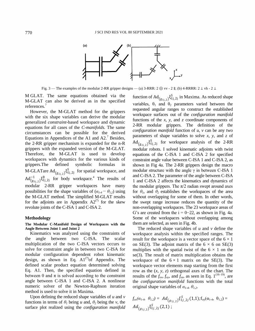
2. The modular grippers of the robots are designed
using the parallel macro modular C-manifolds, as
shown in Fig. 3. The two vertically concentric C-ISA
of the first revolute joints integrate with the two
parallel C-ISA of the second revolute joints shown in
Fig. 3a. The perpendicular C-ISAs of the first and
second joints are constructed modularly to join, as
shown in Fig. 3b.
The macro modular C-manifold determines the
shape variables of the α1-8 − θ1-4 for 4-RRRR in Fig 3.
Additionally, the angles in between skew axes of the
C-ISAs as γ in Fig. 2 are arranged for grasping.
Besides, these grasping arrangements are designed for
the workspaces determined from the results section.
The novelty subject of this article is the development
of the M-GLAT method for derivation of the
constraint-based workspaces with the shape variables
(α1-4 − θ1,2) in the field of the 2-RR gripper
mechanisms. Additionally, the robot dynamics of the
constraint- based workspaces are developed for varied
configurations of α1-4 with ICs of θ1,2. Parallel, serial,
and hybrid 2-RR modular designs define the macro
modular mechanism structure of which numerical
results for specific cases of spatial coordinate
kinematic positions of the configurations are obtained
with generalized symbolic mathematics results of
Fig. 2 — Macro modular C-manifold design of 2-RR serial gripper mechanisms of the γ1, and γ2 for robots — (a) Serial macro modular
C-manifold design; (b) Parallel macro modular C-manifold design
J SCI IND RES VOL 80 SEPTEMBER 2021 770
M GLAT. The same equations obtained via the
M-GLAT can also be derived as in the specified
references.7
However, the M-GLAT method for the grippers
with the six shape variables can derive the modular
generalized constraint-based workspace and dynamic
equations for all cases of the C-manifolds. The same
circumstances can be possible for the derived
Equations in Appendices of the A1 and A2.7 Besides,
the 2-RR gripper mechanism is expanded for the n-R
grippers with the expanded version of the M-GLAT.
Therefore, the M-GLAT is used to develop
workspaces with dynamics for the various kinds of
grippers.The defined symbolic formulas in
M-GLATare Ad g1j_2 ξ1j_2j
S for spatial workspace, and
Ad g1j_2 −1 ξ1j_2j
B for body workspace.4 The results of
modular 2-RR gripper workspaces have many
possibilities for the shape variables of (α1-4 − θ1,2) using
the M-GLAT method. The simplified M-GLAT results
for the adjoints are in Appendix A2(7)
for the skew
revolute joints of the C-ISA 1 and C-ISA 2.
Methodology
The Modular C-Manifold Design of Workspaces with the
Angle Between Joint 1 and Joint 2
Kinematics was analyzed using the constraints of
the angle between two C-ISA. The scalar
multiplication of the two C-ISA vectors occurs to
solve for constraint angle in between two C-ISA for
modular configuration dependent robot kinematic
design, as shown in Eq. A1(7)
of Appendix. The
defined scalar product equation determined solving
Eq. A1. Then, the specified equation defined in
between 0 and π is solved according to the constraint
angle between C-ISA 1 and C-ISA 2. A nonlinear
numeric solver of the Newton-Raphson iteration
method is used to solve it in Maxima.
Upon defining the reduced shape variables of u and v
functions in terms of θ1 being u and, θ2 being the v, the
surface plot realized using the configuration manifold
function of Ad g1j_2 ξ1j_2j
S in Maxima. As reduced shape
variables, θ1 and θ2 parameters varied between the
requested angular ranges to construct the established
workspace surfaces out of the configuration manifold
functions of the x, y, and z coordinate components of
2-RR modular grippers. The definition of the
configuration manifold function of u, v can be any two
parameters of shape variables to solve x, y, and z of
Ad g1j_2 ξ1j_2j
S for workspace analysis of the 2-RR
modular robots. I solved kinematic adjoints with twist
equations of the C-ISA 1 and C-ISA 2 for specified
constraint angle value between C-ISA 1 and C-ISA 2, as
shown in Fig 4a. The 2-RR grippers design the macro
modular structure with the angle γ in between C-ISA 1
and C-ISA 2. The parameter of the angle between C-ISA
1 and C-ISA 2 affects the kinematics and dynamics of
the modular grippers. The π/2 radian swept around axes
for θ1, and θ2 establishes the workspaces of the area
without overlapping for some of them. In other words,
the swept range increase reduces the quantity of the
non-overlapping workspaces. The 23 workspace areas of
G’s are created from the i = 0−22, as shown in Fig. 4a.
Some of the workspaces without overlapping among
them are selected, as seen in Fig. 4b.
The reduced shape variables of u and v define the
workspace analysis within the specified ranges. The
result for the workspace is a vector space of the 6 × 1
on SE(3). The adjoint matrix of the 6 × 6 on SE(3)
multiplies with the spatial twist of the 6 × 1 on the
se(3). The result of matrix multiplication obtains the
workspace of the 6 × 1 matrix on the SE(3). The
workspace vector elements map starting from the first
row as the (x, y, z) orthogonal axes of the chart. The
results of the fox, foy, and foz, as seen in Eq. 1(16–19)
, are
the configuration manifold functions with the total
original shape variables of α1-4, θ1,2.
fox(α1-4, θ1,2) = 𝐴𝑑 𝑔1𝑗 _2 𝜉1𝑗 _2𝑗𝑆 (1,1);foy(α1-4, θ1,2) =
𝐴𝑑 𝑔1𝑗 _2 ξ1𝑗 _2𝑗𝑆 (2,1) ;
Fig. 3 — The examples of the modular 2-RR gripper designs — (a) 3-RRR: 2 ⊚ vv - 2 ∥; (b) 4-RRRR: 2 ⊥ vh - 2 ⊥

SAHIN: MICRO -MACRO MODULAR NONOVERLAPPING GRASP WORKSPACES 771
foz(α1-4, θ1,2) = 𝐴𝑑 𝑔1𝑗 _2 ξ1𝑗 _2𝑗𝑆 (3,1) ... (1)
Upon substitution of the constant values for the α1-4
in the shape variables, the C-manifold of the functions
is generating workspaces using the reduced shape
variables projected on the xyz axes as in Eq. 2.(16–19,23)
frx(u,v) = fox(α1-4, θ1,2) = x(θ1, θ2) , u= θ1, v=θ2 ; fry(u,v)
= foy(α1-4, θ1,2) = y(θ1, θ2) , u= θ1, v=θ2;
frz(u,v) = foz(α1-4, θ1,2) = z(θ1, θ2) , u= θ1, v=θ2 ... (2)
The C-manifold for the reduced shape variables
becomes as in Eq. 3. The ranges for the reduced shape
variables define the characteristics of the C-manifold
in Eq. 3.(16–19)
S1xS
1 = {(x, y, z) ∈R
3: x= frx(u,v) , y= fry(u,v), z=
frz(u,v) : 0 ≤ 𝑢 ≤𝜋
2, 0 ≤ 𝑣 ≤
𝜋
2 }, and M1 = {( θ1,
θ2)| θ1 ∈S1, θ2∈S
1} ... (3)
The Validation and Verifications of the Developed M-GLAT
Method
Upon substitution of the α1,2,3,4=π/2, the M-GLAT
method obtains the EOMs of this known case.24–26
Then, these known equations from the literature
verified the derived equations of motions from
M-GLAT. Additionally, the kinematics equations of
workspaces obtained from M-GLAT are verified
using trigonometry of the determined geometry for
the C-manifold of the α1,2,3,4=π/2. Finally, the derived
adjoints and the inverse adjoints via M-GLAT are
validated and verified with the results already
available in various references for specific simple
configurations of the 2-RR robots.3,4,20
The Robot Dynamics of Skew Revolute Joints for Varied
Configurations of 𝜶𝟏−𝟒 with ICs of 𝜽𝟏−𝟐The symbolic mathematics with Lie algebra
toolbox M-GLAT was developed to derive EOMs.
Thus, the algorithm of the Maxima is developed using
the kinematics of the Lie algebra and the Lagrange
method for derivation of the EOMs. The parameter
values for dynamics are in Table 1.
The derived EOMs have the six shape variables of
the 𝜃1−2 and 𝛼1−4 for skew revolute joints. Gripper
dynamics are defined for skew revolute considering
the varied configurations of 𝛼1−4with ICs of 𝜃1−2.
The dynamics for 𝛼1−4 =𝜋
2 are the known EOMs
24
derived from the generalized EOMs using M-GLAT.
The nonlinear numerical analysis method is described
via the solvable first-order ODEs. Thus, the nonlinear
state-space of the EOMs structured exactly to solve in
the Maxima. Appendix A3 is describing the
fundamental structure of the EOMs derived via
M-GLAT. Having applied these generalized
fundamental EOMs according to the references2–4
, the
EOMs obtained with the defined six shape variables
via M-GLAT. The generalized EOMs using the
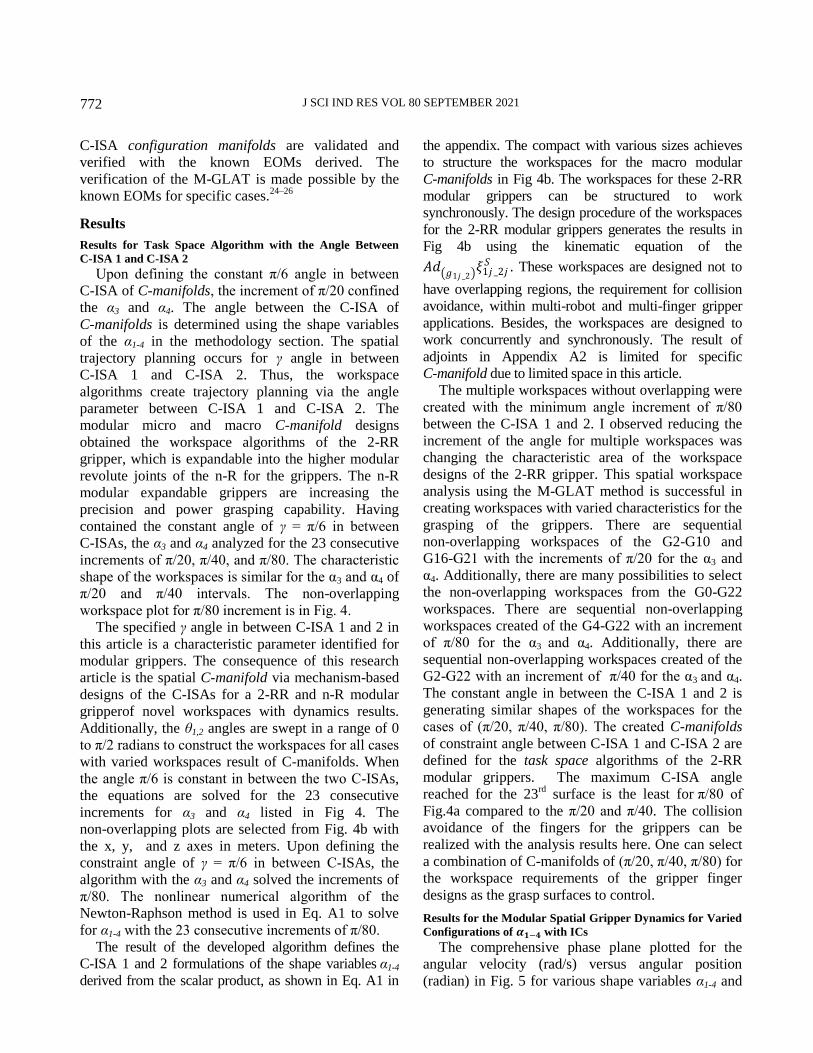
Fig. 4 — The solution of the α1-4 for the constant π/6 angles in
between C-ISA 1 and 2, x, y and z (in meters) — (a) G1-23
sequential increments of π/80 for α3 and α4; (b) Non-overlapping
workspaces of the G1, G10, G22
Table 1 — Modular 2-RR gripper of the robot parameters
l1 0.2 m Iz1 0.2 kgm2 Iy2 0.2 kgm2
r1 0.1 m Ix2 0.2 kgm2 Iz2 0.2 kgm2
r2 0.1 m m1 1 kg m2 1 kg
J SCI IND RES VOL 80 SEPTEMBER 2021 772
C-ISA configuration manifolds are validated and
verified with the known EOMs derived. The
verification of the M-GLAT is made possible by the
known EOMs for specific cases.24–26
Results
Results for Task Space Algorithm with the Angle Between
C-ISA 1 and C-ISA 2
Upon defining the constant π/6 angle in between
C-ISA of C-manifolds, the increment of π/20 confined
the α3 and α4. The angle between the C-ISA of
C-manifolds is determined using the shape variables
of the α1-4 in the methodology section. The spatial
trajectory planning occurs for γ angle in between
C-ISA 1 and C-ISA 2. Thus, the workspace
algorithms create trajectory planning via the angle
parameter between C-ISA 1 and C-ISA 2. The
modular micro and macro C-manifold designs
obtained the workspace algorithms of the 2-RR
gripper, which is expandable into the higher modular
revolute joints of the n-R for the grippers. The n-R
modular expandable grippers are increasing the
precision and power grasping capability. Having
contained the constant angle of γ = π/6 in between
C-ISAs, the α3 and α4 analyzed for the 23 consecutive
increments of π/20, π/40, and π/80. The characteristic
shape of the workspaces is similar for the α3 and α4 of
π/20 and π/40 intervals. The non-overlapping
workspace plot for π/80 increment is in Fig. 4.
The specified γ angle in between C-ISA 1 and 2 in
this article is a characteristic parameter identified for
modular grippers. The consequence of this research
article is the spatial C-manifold via mechanism-based
designs of the C-ISAs for a 2-RR and n-R modular
gripperof novel workspaces with dynamics results.
Additionally, the θ1,2 angles are swept in a range of 0
to π/2 radians to construct the workspaces for all cases
with varied workspaces result of C-manifolds. When
the angle π/6 is constant in between the two C-ISAs,
the equations are solved for the 23 consecutive
increments for α3 and α4 listed in Fig 4. The
non-overlapping plots are selected from Fig. 4b with
the x, y, and z axes in meters. Upon defining the
constraint angle of γ = π/6 in between C-ISAs, the
algorithm with the α3 and α4 solved the increments of
π/80. The nonlinear numerical algorithm of the
Newton-Raphson method is used in Eq. A1 to solve
for α1-4 with the 23 consecutive increments of π/80.
The result of the developed algorithm defines the
C-ISA 1 and 2 formulations of the shape variables α1-4
derived from the scalar product, as shown in Eq. A1 in
the appendix. The compact with various sizes achieves
to structure the workspaces for the macro modular
C-manifolds in Fig 4b. The workspaces for these 2-RR
modular grippers can be structured to work
synchronously. The design procedure of the workspaces
for the 2-RR modular grippers generates the results in
Fig 4b using the kinematic equation of the
𝐴𝑑 𝑔1𝑗 _2 𝜉1𝑗 _2𝑗𝑆 . These workspaces are designed not to
have overlapping regions, the requirement for collision
avoidance, within multi-robot and multi-finger gripper
applications. Besides, the workspaces are designed to
work concurrently and synchronously. The result of
adjoints in Appendix A2 is limited for specific
C-manifold due to limited space in this article.
The multiple workspaces without overlapping were
created with the minimum angle increment of π/80
between the C-ISA 1 and 2. I observed reducing the
increment of the angle for multiple workspaces was
changing the characteristic area of the workspace
designs of the 2-RR gripper. This spatial workspace
analysis using the M-GLAT method is successful in
creating workspaces with varied characteristics for the
grasping of the grippers. There are sequential
non-overlapping workspaces of the G2-G10 and
G16-G21 with the increments of π/20 for the α3 and
α4. Additionally, there are many possibilities to select
the non-overlapping workspaces from the G0-G22
workspaces. There are sequential non-overlapping
workspaces created of the G4-G22 with an increment
of π/80 for the α3 and α4. Additionally, there are
sequential non-overlapping workspaces created of the
G2-G22 with an increment of π/40 for the α3 and α4.
The constant angle in between the C-ISA 1 and 2 is
generating similar shapes of the workspaces for the
cases of (π/20, π/40, π/80). The created C-manifolds
of constraint angle between C-ISA 1 and C-ISA 2 are
defined for the task space algorithms of the 2-RR
modular grippers. The maximum C-ISA angle
reached for the 23rd
surface is the least for π/80 of
Fig.4a compared to the π/20 and π/40. The collision
avoidance of the fingers for the grippers can be
realized with the analysis results here. One can select
a combination of C-manifolds of (π/20, π/40, π/80) for
the workspace requirements of the gripper finger
designs as the grasp surfaces to control.
Results for the Modular Spatial Gripper Dynamics for Varied
Configurations of 𝜶𝟏−𝟒 with ICs
The comprehensive phase plane plotted for the
angular velocity (rad/s) versus angular position
(radian) in Fig. 5 for various shape variables α1-4 and

SAHIN: MICRO -MACRO MODULAR NONOVERLAPPING GRASP WORKSPACES 773
ICs of the θ1,2 angles with the C-ISA configuration
manifolds. While the kinematics equations structure the
constraint-based design of the workspaces, the
dynamics with the derived EOMs apply to the skew
revolute joints for developing the grasp planning of the
grippers. The dynamics of the EOMs with workspaces
are needed for realizing the grasp planning.
The motion strategies for various initial conditions
of θ1,2 angles are analyzed based on the C-manifold of
the C-ISA with shape variables of the α1-4. M-GLAT
is capable of deriving the constraint based workspaces
with dynamics of the EOMs. Responses based on the
various skew axes of α1-4 for the ICs of the θ1,2
construct the velocity versus position requirements for
the actuator design of the modular 2-RR grippers in
the skew revolute joints. The quantity of sine and
cosine terms of the EOMs are decreasing when the
shape variables of the α1-4 are (∀ 𝛼1−4 ∈ 𝑅 𝑓𝑜𝑟 𝑖 ∈
ℤ, 𝛼1−4 = 𝑖𝜋
2).
17 The cosine and sine terms of
the iπ/2 are zero or 1 with orthogonal or parallel
axes. Therefore, the results of the EOMs are
simplified when the two of the α1-4 are iπ/2 for the
integer i values. The geometry transforms into the
horizontal orientation with parallel non-skew axes
when the α1-4 angles are equal to the π/2 for skew
revolute joints. The results for the created
configurations are shown in Fig. 5 of the (α1-4= π/6,
π/3, π/6, π/3) respectively for the ICs of the θ1,2
angles. The legends of the lines in the plots for ICs
have dashed line represents the (θ2= π/6, θ1=0), and
solid line with star point represents the (θ2= π/3,
θ1=0). The simulated time for EOMs is 40 seconds.
The ICs for the phase plots of the 𝜃2 and 𝜃 2 are (θ2=
π/3, π/6) and (θ1= 0, 0) for C-manifold of (α1-4= π/6,
π/3, π/6, π/3) in Fig. 5.
The phase plots are the solutions of the derived
EOMs via the M-GLAT method for the substituted
values of the α1-4. The results of the α1-4 = π/2 for the
position and velocity plots are zero since this scenario
is a complete horizontal configuration for both the
first and second links. The dynamics of the double
pendulum problem in the literature is the most
widespread application in controls. Therefore, it is
fundamental to obtain the constraint-based most
comprehensive dynamics and kinematics equations
that have the most applicability in the multibody
dynamics control problems.
Discussion
The M-GLAT of the micro and macro gripper
mechanism is derived and analyzed workspaces with
dynamics for the specified constant angle between
C-ISA 1 and C-ISA 2. The developed rule-based and
constraint-angle dependent workspace analyses can
serve to progress in the field of the algorithm for
task-space based motions, which are reliant on the
modular C-manifold design with shape variables of
the (α1-4−θ1,2). Additionally, the novel dynamics
equations determine these task-space dependent
algorithm development with novel EOMs based on
the same shape variables of the (α1-4 − θ1,2). The
qualifications of the advanced robotic grasp
technologies rely on the requirement of the surface
trajectory tracking control via the 6-DOF closed-loop
design27
Since the problem of path planning for
multiple robots requires an accurate model of the
workspaces28
, this article contributes to establishing
accurate workspaces of 2-RR and expandable n-R
grippers for path planning and grasping. The
cost-effective modularity with path planning29
is
feasible using the state-of-the-art technologies of soft
robotics30
and mobile household robots.31
The skew axes of n-R grippers with specified
dynamics and constraint based workspace equations,
as derived with this article here, have potential
progress in the design of the multi-fingered robotic
hands.10
The complete constraint- based parametric
workspaces with dynamics analyses of the serial
mechanisms are not available for the grippers with
skew revolute. Thus, the research in constraint of
angle in between C-ISA based workspace with
dynamic completed of this article can lead the design
of the skew axis related hands and wrist mechanisms
with functional designs using the M-GLAT developed
herein. The nonlinear EOMs are solved numerically
Fig. 5 — x and y axes are 𝜃2 (rd) and 𝜃 2(rd/sec) respectively for
C-manifold of (α1-4= π/6, π/3, π/6, π/3)
J SCI IND RES VOL 80 SEPTEMBER 2021
774
using the Runge-Kutta (RK) method in Maxima. All
the EOMs for various C-manifolds of α1-4 can be
generated using the general EOMs with specified
values of the α1-4. Then, the differential equations of
the substituted α1-4 angles are solved for the ICs of the
θ1,2 using the RK. The phase plots of the simplified
EOMs derived using M-GLAT are validated and
verified by the known EOMs for 2-RR robots. These
known EOMs are derived and available as the double
pendulum problems in the literature.24–26
Upon determining the task space and workspace
for 2-RR modular grippers, the details of the
configuration dependent modular design can further
progress via specifying the C-manifolds. While the
C-ISA 1 manifold has the shape variables of the θ1
and 𝛼1,2, the C-ISA 2 has the shape variables of θ2
with α3,4. After selecting the shape space for
C-manifold as S1×S
1 or S
2×S
2, the 2-RR modular
robot design constructs the requirements of the task
spaces for the robotic systems considering the shape
variables. Learning algorithm manifolds for dexterous
fingers of skew revolute joints can be defined for the
grasp planner utilizing the kinematic and dynamic
equations developed as C-manifolds with the article
here. The created sequential non-overlapping
workspaces, in the results section herein, are
convenient in grasping the homogeneous symmetrical
shapes stably with multiple fingers.
Conclusions
The micro and macro 2-RR modular grippers were
investigated and designed via configuration dependent
modular designs of C-ISA in this article. These
configuration dependent modular components were
analyzed in the previous sections as the C-ISA angles,
which are modified for the configuration of the 2-RR
modular grippers using the manifold of the Euclidean
space in body coordinate. The fingers without
collision for the grippers were designed based on the
non-overlapping workspaces developed here. The
constraint angle design in between axes of the skew
revolute joints provides the contained specific grasp
capability of the gripper. This design approach
produces dexterity with the modular grasp
workspaces for the gripper fingers with skew revolute
joints. The constraint based workspaces with
dynamics of the EOMs herein are the value added
analyses capability of the developed M-GLAT for
the spatial micro and macro modular gripper
mechanisms.
The developed method of M-GLAT conveys the
mapping from the Lie group SE(3) to the Lie algebra
se(3) through the subjects of the differential
geometry. The specified constraint based analyses of
the 2-RR modular gripper workspaces with dynamics
of equations for skew revolute joint are revealed. The
novel workspaces were created for multiple modular
2-RR grippers with and without overlappings. The
modular grippers have common mechanisms that can
be modified as a modular configuration-based design
approach for increasing the functionality using the
abstract mathematics of the differential geometry.
These common mechanisms of the modular robots
can be structured using the manifolds of varied shapes
for the required configurations. The mechanism
configurations of the shape variables θ1,2 ,α1−4 were
changed dynamically for 2-RR modular robots via the
angle in between the C-ISA 1 and C-ISA -2.
The 2-RR modular grippers of the common
mechanisms are tested via the micro and macro
C-manifolds of the kinematic equations derived from the
M-GLAT method. The algorithm results unveil the
diversification of the created workspaces through the
α1−4 shape variables of the C-ISA 1 and 2. The high
potential of the structured workspaces handles to
manipulate the 2-RR modular grippers in widespread
automation applications. Modular configuration
manifolds of the shape variables (α1-4 − θ1,2) were created
of the skew revolute joints for 2-RR through the
dynamics and kinematics equations. Many applications
with coherent results further progressed with the
modularity and versatility of the serial grippers. The
systematic workspace methods developed were applied
with the M-GLAT method for modular C-manifold of
2-RR and expandable n-R grippers. The algorithms of
task spaces have relied on the novel workspaces
developed with this article. Finally, the designed novel
dexterous multi-grippers of the modular 2-RR and n-R
C-manifolds can program the task spaces precisely by
applying these algorithms. Furthermore, this modularity
is crucial for the mechatronic systems integrated into
sensory-robotics applications.
Acknowledgments
This research did not receive any specific grant
from funding agencies in the public, commercial, or
not-for-profit sectors.
References 1 Zeghloul S, Laribi M A & Arevalo J S S, Advances in
Service and İndustrial Robotics (Springer) 2020, 1–609.

SAHIN: MICRO -MACRO MODULAR NONOVERLAPPING GRASP WORKSPACES
775
2 Müller A, Screw and Lie group theory in multibody
dynamics recursive algorithms and equations of motion of
tree-topology systems, Multibody Syst Dyn, 42 (2018)
219–248.
3 Müller A, Screw and Lie group theory in multibody
kinematics motion representation and recursive kinematics of
tree-topology systems, Multibody Syst Dyn, 43 (2018) 37–70.
4 Murray R M, Li Z & Sastry S S, A Mathematical İntroduction to
Robotic Manipulation, (CRC Press)1994, 1–474.
5 Wei J & Dai J S, Lie group based type synthesis using
transformation configuration space for reconfigurable
parallel mechanisms with bifurcation between spherical
motion and planar motion, ASME J Mech Des, 142(6) (2020)
1–13. https://doi.org/10.1115/1.4045042.
6 Müller A, An overview of formulae for the higher-order
kinematics of lower-pair chains with applications in robotics
and mechanism theory, Mech Mach Theory, 142 (2019)
1–35.
7 Reiter A, Optimal Path and Trajectory Planning for Serial
Robots (Springer) 2020, 1–201. https://doi.org/10.1007/978-
3-658-28594-4.
8 Ayalon Y, Damti L & Zarrouk D, Design and modelling
of a minimally actuated serial robot, IEEE Robot Autom
Lett, 5(3) (2020) 4899 –4906. https://doi.org/10.1109/
LRA.2020.3004783.
9 Nichols J A, Bednar M S, Havey R M & Murray W M,
Decoupling the wrist: A cadaveric experiment examining
wrist kinematics following midcarpal fusion and
scaphoid excision, J Appl Biomech, 33(1) (2017) 12–23.
https://doi.org/10.1123/jab.2015-0324.
10 Deemyad T, Hassanzadeh N & Perez-Gracia A, Coupling
mechanisms for multi-fingered robotic hands with skew axes,
344–352 (2019). in Mechanism Design for Robotics, edited
by Gasparetto A & Ceccarelli M, MEDER 2018,
Mechanisms and Machine Science, vol 66, (Springer Cham)
https://doi.org/10.1007/978-3-030-00365-4_41.
11 Sommer III H J & Miller N R, A technique for kinematic
modeling of anatomical joints, ASME J Biomech Eng, 102(4)
(1980) 311–317, https://doi.org/10.1115/1.3138228.
12 Thiruvengadam S & Miller K A, Geometric algebra based
higher dimensional approximation method for statics and
kinematics of robotic manipulators, Adv Appl Clifford
Algebras, 30(17) (2020) 1–43, https://doi.org/10.1007/s
00006-019-1039-z.
13 Peng S, Yan Biao L, Ze Sheng W, Ke C, Bo C, Xi Z, Jun Z
& Yi Y, Inverse displacement analysis of a novel hybrid
humanoid robotic arm, Mech Mach Theory, 147 (2020) 1–21.
DOI:10.1016/j.mechmachtheory.2019.103743.
14 Figliolini G, Rea P & Angeles J, The Synthesis of the axodes
of RCCC linkages, J Mech Robot, 8 (2016) 1–9.
15 Flores P, Modeling and simulation of wear in revolute
clearance joints in multibody systems, Mech Mach Theory,
44(6) (2009) 1211–1222.
16 Silvia E & Harald S, Applying differential geometry to
kinematic modeling in mobile robotics, 2005 WSEAS Int
Conf Dynam Syst Control, (Venice, Italy) November 2–4,
2005, 106–112.
17 Novelia A & O’Reilly O M, On the dynamics of the eye:
Geodesics on a configuration manifold, motions of the gaze
direction and Helmholtz’s Theorem, Nonlinear Dyn, 80
(2015) 1303–1327, https://doi.org/10.1007/s11071-015-
1945-0.
18 Travers M, Whitman J & Choset H, Shape-based coordination in
locomotion control, Int J Robot Res, 37(10) (2018) 1253–1268.
https://doi.org/10.1177/0278364918761569.
19 Watterson M, Liu S, Sun K, Smith T & Kumar V, Trajectory
optimization on manifolds with applications to quadrotor
systems, Int J Robot Res, 39(2–3) (2020) 303–320,
https://doi.org/10.1177/0278364919891775.
20 From P J, Jan Tommy Gravdahl & Pettersen K Y, Vehicle-
Manipulator Systems Modeling for Simulation, Analysis, and
Control (Springer) 2014, 1–388.
21 Giovanni S L, Michael S, Dimitris T P, Arianna M & Paolo
D, Polychaete-like undulatory robotic locomotion in
unstructured substrates, IEEE Trans Robot, 23(6) (2007)
1200–1212. https://doi.org/10.1109/TRO.2007.909791.
22 Lee K, Wang Y & Zheng C, TWISTER Hand:
Underactuated robotic gripper ınspired by origami twisted
tower, IEEE Trans Robot, 36(2) (2020) 488–500, DOI:
10.1109/TRO.2019.2956870.
23 Belta C & Kumar V, Abstraction and control for groups of
robots, IEEE Trans Robot, 20(5) (2004) 865–875,
https://doi.org/10.1109/TRO.2004.829498.
24 Awrejcewicz J & Sendkowski D, Geometric analysis of the
dynamics of a double pendulum, J Mech Mater Struct, 2(8)
(2007) 1421–1430, https://doi.org/10.2140/jomms.2007.2.1421.
25 Rafat M Z & Wheatland M S & Bedding T R, Dynamics of a
double pendulum with distributed mass, Am J Phys, 77(216)
(2009) 216–223, https://doi.org/10.1119/1.3052072.
26 Sun N, Wu Y, Chen H & Fang Y, An energy-optimal
solution for transportation control of cranes with double
pendulum dynamics: Design and experiments, Mech Syst
Signal Process, 102 (2018) 87–101. https://doi.org/
10.1016/j.ymssp.2017.09.027.
27 Song S, Zeng A, Lee J & Funkhouser T, Grasping in the
wild: Learning 6DoF closed-loop grasping from low-cost
demonstrations, IEEE Robot Autom Lett, 5(3) July 2020,
https://doi.org/10.1109/LRA.2020.3004787.
28 Gómez-Bravo F, Carbone G & Fortes J C, Collision free
trajectory planning for hybrid manipulators, Mechatronics, 22(6)
(2012) 836–851. https://doi.org/10.1016/j.mechatronics.
2012.05.001.
29 Kalpitha N & Murali S, Optimal path planning using rrt for
dynamic obstacles, J Sci Ind Res, 79 (2020) 513–516.
30 Dilibal S, Sahin H, Danquah O, Emon M O F & Choi J W,
Additively manufactured custom soft gripper with embedded
soft force sensors for an ındustrial robot, Int J Precis Eng
Manuf, 22 (2021) 709–718, https://doi.org/10.1007/s12541-
021-00479-0.
31 Sahin H & Guvenc L, Household robotics: autonomous
devices for vacuuming and lawn mowing, IEEE Control Syst
Mag, 27(2) (2007) 20–96, doi: 10.1109/MCS.2007.
338262.
J SCI IND RES VOL 80 SEPTEMBER 2021 776
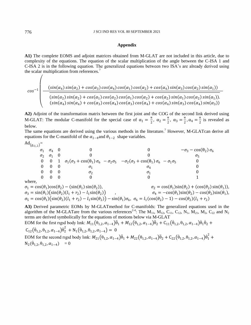
Appendix
A1) The complete EOMS and adjoint matrices obtained from M-GLAT are not included in this article, due to
complexity of the equations. The equation of the scalar multiplication of the angle between the C-ISA 1 and
C-ISA 2 is in the following equation. The generalized equations between two ISA’s are already derived using
the scalar multiplication from references.7
𝑐𝑜𝑠−1
𝑠𝑖𝑛 𝛼4 𝑠𝑖𝑛 𝛼2 + 𝑐𝑜𝑠 𝛼3 𝑐𝑜𝑠 𝛼4 𝑐𝑜𝑠 𝛼1 𝑐𝑜𝑠 𝛼2 + 𝑐𝑜𝑠 𝛼4 𝑠𝑖𝑛 𝛼3 𝑐𝑜𝑠 𝛼2 𝑠𝑖𝑛 𝛼1
𝑠𝑖𝑛 𝛼2 𝑠𝑖𝑛 𝛼2 + 𝑐𝑜𝑠 𝛼1 𝑐𝑜𝑠 𝛼2 𝑐𝑜𝑠 𝛼1 𝑐𝑜𝑠 𝛼2 + 𝑐𝑜𝑠 𝛼2 𝑠𝑖𝑛 𝛼1 𝑐𝑜𝑠 𝛼2 𝑠𝑖𝑛 𝛼1 . 𝑠𝑖𝑛 𝛼4 𝑠𝑖𝑛 𝛼4 + 𝑐𝑜𝑠 𝛼3 𝑐𝑜𝑠 𝛼4 𝑐𝑜𝑠 𝛼3 𝑐𝑜𝑠 𝛼4 + 𝑐𝑜𝑠 𝛼4 𝑠𝑖𝑛 𝛼3 𝑐𝑜𝑠 𝛼4 𝑠𝑖𝑛 𝛼3
A2) Adjoint of the transformation matrix between the first joint and the COG of the second link derived using
M-GLAT: The modular C-manifold for the special case of α1 = π
2, α2 =
π
2, α3 =
π
2,α4 =
π
2 is revealed as
below.
The same equations are derived using the various methods in the literature.7 However, M-GLATcan derive all
equations for the C-manifold of the 𝛼1−4and 𝜃1−2 shape variables.
Ad g1j_2 =
𝜎1 𝜎4 0 0 0 −𝜎3 − cos θ2 𝜎6
𝜎2 𝜎1 0 0 0 𝜎5
0 0 1 𝜎1 𝜎3 + cos θ1 𝜎6 − 𝜎2𝜎5 −𝜎2 𝜎3 + cos θ1 𝜎6 − 𝜎1𝜎5 00 0 0 𝜎1 𝜎4 00 0 0 𝜎2 𝜎1 00 0 0 0 0 1
where,
𝜎1 = cos 𝜃1 cos 𝜃2 − sin 𝜃1 sin 𝜃2 , 𝜎2 = cos 𝜃1 sin 𝜃2 + cos 𝜃2 sin 𝜃1 ,
𝜎3 = sin 𝜃1 sin 𝜃2 𝑙1 + 𝑟2 − 𝑙1sin 𝜃2 , 𝜎4 = −cos 𝜃1 sin 𝜃2 − cos 𝜃2 sin 𝜃1 ,
𝜎5 = cos 𝜃1 sin 𝜃2 𝑙1 + 𝑟2 − 𝑙1sin 𝜃2 − sin 𝜃1 𝜎6, 𝜎6 = 𝑙1 cos 𝜃2 − 1 − cos 𝜃2 𝑙1 + 𝑟2
A3) Derived parametric EOMs by M-GLATmethod for C-manifolds: The generalized equations used in the
algorithm of the M-GLATare from the various references2-4
: The M11, M12, C11, C12, N1, M21, M2, C22 and N2
terms are derived symbolically for the equations of motions below via M-GLAT
EOM for the fırst rıgıd body lınk: 𝑀11 θ1,2,𝛼1−4 θ 1 +𝑀12 θ1,2,𝛼1−4 θ 2 + C11 θ 1,2, θ1,2 ,𝛼1−4 θ 1θ 2 +
C12 θ 1,2, θ1,2 ,𝛼1−4 θ 22
+ N1 θ 1,2, θ1,2 ,𝛼1−4 = 0
EOM for the second rıgıd body lınk: 𝑀21 θ1,2,𝛼1−4 θ 1 +𝑀22 θ1,2,𝛼1−4 θ 2 + C22 θ 1,2 , θ1,2,𝛼1−4 θ 12
+
N2(θ 1,2, θ1,2 ,𝛼1−4) = 0


