Embed Size (px)
Citation preview

machines
Article
The Modelling, Simulation and FPGA-BasedImplementation for Stepper Motor Wide RangeSpeed Closed-Loop Drive System Design
Chiu-Keng Lai *, Jhang-Shan Ciou and Chia-Che TsaiDepartment of Electrical Engineering, National Chin-Yi University of Technology, Taichung 41170, Taiwan;[email protected] (J.-S.C.); [email protected] (C.-C.T.)* Correspondence: [email protected]; Tel.: +886-4-23924505; Fax: 886-4-23924419 (ext. 7216)
Received: 27 August 2018; Accepted: 22 October 2018; Published: 1 November 2018�����������������
Abstract: Owing to the benefits of programmable and parallel processing of field programmablegate arrays (FPGAs), they have been widely used for the realization of digital controllers and motordrive systems. Furthermore, they can be used to integrate several functions as an embedded system.In this paper, based on Matrix Laboratory (Matlab)/Simulink and the FPGA chip, we design andimplement a stepper motor drive. Generally, motion control systems driven by a stepper motor canbe in open-loop or closed-loop form, and pulse generators are used to generate a series of pulsecommands, according to the desired acceleration/run/deceleration, in order to the drive system torotate the motor. In this paper, the speed and position are designed in closed-loop control, and avector control strategy is applied to the obtained rotor angle to regulate the phase current of thestepper motor to achieve the performance of operating it in low, medium, and high speed situations.The results of simulations and practical experiments based on the FPGA implemented control systemare given to show the performances for wide range speed control.
Keywords: Matlab/Simulink; stepper motor; FPGA; speed control; closed-loop control
1. Introduction
Stepper motors are adopted in a variety of drive applications because of their high precision ofpositioning, low costs of the driver, simplicity of operation, and high torque at low speeds. However,stepper motors suffer from some drawbacks such as missed steps, decreased torque at high speeds,resonances, and high power consumption. Speed and position closed-loop and current vector controlare good choices to overcome these drawbacks mentioned above.
Regarding closed-loop position control, which usually uses the encoder to compensate for theposition error, the end point can be adjusted by commanding additional step pulses to bring the motorback to the correct position. Furthermore, closed-loop control can also operate the stepper motor inmicrostepping mode, and the accuracy of position can be verified and adjusted dependent on theresolution of the encoder. The control mode of the stepper motor is thus gradually developed intoclosed-loop control, and adopts a highly efficient controller to achieve better performance [1–3] ascompared with open-loop control.
Vector control has been widely used in induction motors [4] and permanent magnet synchronousmotors (PMSMs) [5,6]. Because of the fact that the hybrid stepper motor is similar to permanentmagnet synchronous motors or brushless DC motors in the mechanism of action, the theoretical basisand analysis foundation of the vector control for the stepper motor are also proposed [1,7]. To thisend, the vector control strategy is used in the drive system design of the hybrid stepper motor. As thetwo-phase hybrid stepper motors are different from the conventional three-phase PMSMs or brushlessDC motors (BLDCMs), we do not need to construct the functions of 3φ − 2φ transformations.
Machines 2018, 6, 56; doi:10.3390/machines6040056 www.mdpi.com/journal/machines

Machines 2018, 6, 56 2 of 14
As a result of their flexibility and high performance, field programmable gate array (FPGA)has been widely used in hardware controller realization. Some examples include the design of theProportional-Integral-Derivative (PID) controller [8] and the fuzzy controller [5]. It is also appliedin power electronics circuits [9] and drive system designs of PMSMs [5,6,10], induction motors [4],switched reluctance motors [11], and BLDCMs [12]. Furthermore, FPGA is suitable for the developmentof an embedded system or a system on a chip (SoC), and the developed embedded system can be apart of a complete motion control system.
In this study, we use FPGA in the stepper motor drive system design, and adopt vector controlfor the regulation of the inner current loop. Furthermore, to get the trapezoidal velocity profile forpoint to point command, an encoder is used to close the position and velocity control loop. All thehardware circuits are realized by FPGA. The design starts from building the drive system in a MatrixLabaratory (Matlab)/Simulink platform [9], and the software system is simulated on Quartus II andModelsim [10,13]. The resulting digital hardware system is in the type of Verilog code and is practicallyimplemented on an Altera Cyclone III FPGA. Finally, the developed hardware control system and thepower module are applied to a hybrid stepper motor to show the validity and performance.
The contents of the paper are as follows. In Section 2, the experimental setup and system modellingare presented. Then, the simulation results and discussions are given for the built system in Section 3.The experimental results are shown in Section 4. Finally, the conclusions are given in Section 5.
2. The Experimental Setup and Modelling of the Developed Drive System
2.1. The Experimental Setup
The experimental hardware setup of the proposed system is shown in Figure 1. Figure 1a includesthe FPGA-based control board and power module board. In the former, the FPGA IC, analog todigital converters (ADCs), and digital to analog converters (DACs) are shown. In the latter, themain components are two H-bridge circuits and two Hall current sensors. Figure 1a also displaysthe DC power supply and hybrid stepper motor. In Figure 1b, the experimental motor is fixed andaxis-coupled to a disk load where six counterweights can be inserted or removed to change the inertiaof the load. The FPGA chip is used to develop the hardware control system, which includes the currentregulator, the speed controller, the position controller, and the encoder up/down counter. The encodercounter module accepts the A/B/Z phase pulse signals and outputs the four times precision pulsesignal as the position feedback. The position control module is designed to accept the pulse stringcommands and run the proportional control, which has a sampling frequency of 2 kHz. The fourtimes precision encoder counter module feeds back the accumulated angle to the speed/positioncontrollers to complete the closed-loop control. The sampling frequency for the speed control loopis also set at 2 kHz. The current control loops are based on vector control, and operated at 20 kHzsampling frequency. The main control board also includes two serial ADCs, two serial DACs, and Hallcurrent sensors. The ADCs are used to get the analog current signals of phases A and B detected byHall current sensors. The DAC is used to output the controlled variables inside the control system,where the variables are intended to be checked and compared. The waveforms of the DACs are shownon the oscilloscope, and they are captured for illustration and comparison. The ADCs are operatedat 20 kHz to match the current vector control loop, while the DACs are operated at random by theprogramming. The stepper motor is a hybrid one with rated current 2A, and the DC bus voltage is36 V. Furthermore, the stepper motor is equipped with a 20,000 pulses/rev encoder. The contents ofthe encoder counter are provided for the position and speed feedback, as well as for the coordinatetransformation between the stationary reference frame and synchronous rotation reference frame.The block diagram for the proposed system is shown in Figure 2.

Machines 2018, 6, 56 3 of 14
Machines 2018, 6, x FOR PEER REVIEW 3 of 15
(a)
(b)
Figure 1. The setup for experiment. (a) The field programmable gate array (FPGA) board and power
module; (b) the experimental platform.
Figure 2. The block diagram of the stepper motor drive system. DAC—digital to analog converter;
ADC—analog to digital converter.
2.2. The Modelling of the Stepper Motor
The electrical equations and the generated torque for the two-phase hybrid stepper motor are
shown in (1)–(3) [3].
(1)
(2)
(3)
Hybrid
Stepper Motor
Inertia Load
(Disk)
Counterweight
2 Phases/4 Wires
Hybrid Stepper
Motor
Power
Stage
Current
Vector
Control
Speed
Controller
Position
Controller
20000 p/rev
Encoder
Pulse
Generator
+ +
- -
FPGA-based Controllers36 V
m
msm T/ ADC
Up/DownCounter
DAC
e
1/P
L
vP
L
Ki
L
R
dt
di amm
ma
a ++−= )sin(
L
vP
L
Ki
L
R
dt
di bmm
mb
b +−−= )cos(
)]cos()sin([ mbmame PiPiKT +−=
Figure 1. The setup for experiment. (a) The field programmable gate array (FPGA) board and powermodule; (b) the experimental platform.
Machines 2018, 6, x FOR PEER REVIEW 3 of 15
(a)
(b)
Figure 1. The setup for experiment. (a) The field programmable gate array (FPGA) board and power
module; (b) the experimental platform.
Figure 2. The block diagram of the stepper motor drive system. DAC—digital to analog converter;
ADC—analog to digital converter.
2.2. The Modelling of the Stepper Motor
The electrical equations and the generated torque for the two-phase hybrid stepper motor are
shown in (1)–(3) [3].
(1)
(2)
(3)
Hybrid
Stepper Motor
Inertia Load
(Disk)
Counterweight
2 Phases/4 Wires
Hybrid Stepper
Motor
Power
Stage
Current
Vector
Control
Speed
Controller
Position
Controller
20000 p/rev
Encoder
Pulse
Generator
+ +
- -
FPGA-based Controllers36 V
m
msm T/ ADC
Up/DownCounter
DAC
e
1/P
L
vP
L
Ki
L
R
dt
di amm
ma
a ++−= )sin(
L
vP
L
Ki
L
R
dt
di bmm
mb
b +−−= )cos(
)]cos()sin([ mbmame PiPiKT +−=
Figure 2. The block diagram of the stepper motor drive system. DAC—digital to analog converter;ADC—analog to digital converter.
2.2. The Modelling of the Stepper Motor
The electrical equations and the generated torque for the two-phase hybrid stepper motor areshown in (1)–(3) [3].
dia
dt= −R
Lia +
Km
Lωm sin(Pθm) +
va
L(1)
dibdt
= −RL
ib −Km
Lωm cos(Pθm) +
vbL
(2)
Te = Km[−ia sin(Pθm) + ib cos(Pθm)] (3)
The mechanic equation is as follows:
Jdωm
dt+ Bωm + TL + Fc sin(4Pθm) = Te (4)
with the following relation:θe = Pθm (5)
For those equations, va and vb are the voltages of phases A and B, respectively; ia and ib are thephase currents of phases A and B, respectively; R is the resistor; L is the inductance; Km is the torque

Machines 2018, 6, 56 4 of 14
constant; θe is the electrical rotor position; P is the pole pair; Te is the generated torque; J is the rotorinertia; B is the viscous fraction coefficient; ωm is the shaft speed; θm is the shaft position; and Fc is thefourth harmonic detent torque constant.
With the modelling of (1)–(5), the block, as shown in Figure 3 and named as “Stepper Motor”,is built using Matlab/Simulink. Furthermore, to realize the current vector control, the coordinatetransformation for current between the two-phase stationary reference frame (2s) and two-phasesynchronous rotation reference frame (2e) are executed by the blocks of 2s to 2e and 2e to 2s, respectively,and the relations are given by the following:
a = d cos(θe)− q sin(θe)
b = d sin(θe) + q cos(θe)(6)
where a and b are the variables in the stationary reference frame, and d and q are the variables in thesynchronous rotation reference frame.
Four controllers are set in the drive system. The d-axis current command is set to 0 for the systemcontrolled under the base speed, and is set to a negative amount for the field weaken operation, andthe q-axis current command is from the output of the speed controller. To the object of field weaken
control, the space voltage, vre f =√
v2d + v2
q, as shown in Figure 4, is placed at Vre f−β with a leadingangle β, instead of the normal position. In Figure 3, all the blocks are realized by FPGA except thestepper motor. Normally, an inner loop should have a faster sampling time than the outer loop, wethus set the sampling frequency to 20 kHz for the electrical loop (current control), and to 2 kHz for themechanic loop (position/velocity control).
Machines 2018, 6, x FOR PEER REVIEW 4 of 15
The mechanic equation is as follows:
(4)
with the following relation:
(5)
For those equations, and are the voltages of phases A and B, respectively; and
are the phase currents of phases A and B, respectively; is the resistor; is the inductance;
is the torque constant; is the electrical rotor position; is the pole pair; is the generated
torque; is the rotor inertia; is the viscous fraction coefficient; is the shaft speed; is
the shaft position; and is the fourth harmonic detent torque constant.
With the modelling of (1)–(5), the block, as shown in Figure 3 and named as “Stepper Motor”, is
built using Matlab/Simulink. Furthermore, to realize the current vector control, the coordinate
transformation for current between the two-phase stationary reference frame (2s) and two-phase
synchronous rotation reference frame (2e) are executed by the blocks of 2s to 2e and 2e to 2s,
respectively, and the relations are given by the following:
(6)
where a and b are the variables in the stationary reference frame, and d and q are the variables in the
synchronous rotation reference frame.
Four controllers are set in the drive system. The d-axis current command is set to 0 for the system
controlled under the base speed, and is set to a negative amount for the field weaken operation, and
the q-axis current command is from the output of the speed controller. To the object of field weaken
control, the space voltage, , as shown in Figure 4, is placed at with a
leading angle , instead of the normal position. In Figure 3, all the blocks are realized by FPGA
except the stepper motor. Normally, an inner loop should have a faster sampling time than the outer
loop, we thus set the sampling frequency to 20 kHz for the electrical loop (current control), and to 2
kHz for the mechanic loop (position/velocity control).
Figure 3. The block diagram for the drive system.
emcLmm TPFTB
dt
dJ =+++ )4sin(
me P =
av bv ai bi
R L mK
e P eT
J B m m
cF
)cos()sin(
)sin()cos(
ee
ee
qdb
qda
+=
−=
22qdref vvv += −refV
Figure 3. The block diagram for the drive system.Machines 2018, 6, x FOR PEER REVIEW 5 of 15
.
Figure 4. The vector control for phase currents.
2.3. The Realization of the Drive System by FPGA
To realize the overall drive systems with FPGA, we first design the systems in Matlab/Simulink,
and then simulate them using Modelsim to verify the correctness. Finally, the resulting block systems
are converted into Verilog codes. The hardware systems are shown in Figure 5 where the block
named as FPGA code located at the center in yellow is the hardware model of the proposed vector
control drive system. The performances of the system by applying the hardware code to
current/velocity/position controls will be shown in next section.
Some of the mathematic functions are illustrated to show the design. The PI controllers are
realized in parallel as the block diagram shown in Figure 6a with the discrete-time transfer function
(7).
(7)
where , , and are the proportional gain, integral gain, and sampling time, respectively.
For all the designed system, the data bus is set as 32 bits with fixed-point operation, such as
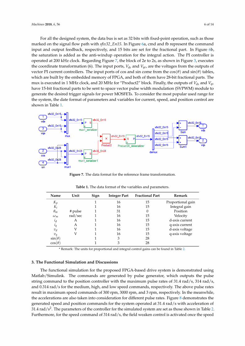
those marked on the signal flow path with sfix32_En15. In Figure 6a, cmd and fb represent the
command input and output feedback, respectively, and 15 bits are set for the fractional part. In Figure
6b, the saturation is added as the anti-windup operation for the integral action. The PI controller is
operated at 200 kHz clock. Regarding Figure 7, the block of 2e to 2s, as shown in Figure 3, executes
the coordinate transformation (6). The input ports, and , are the voltages from the outputs
of vector PI current controllers. The input ports of cos and sin come from the and
tables, which are built by the embedded memory of FPGA, and both of them have 28-bit fractional
parts. The mux is executed in 1 MHz clock, and 20 MHz for “Product2” block. Finally, the outputs of
and have 15-bit fractional parts to be sent to space vector pulse width modulation
(SVPWM) module to generate the desired trigger signals for power MOSFETs. To consider the most
popular used range for the system, the date format of parameters and variables for current, speed,
and position control are shown in Table 1.
A
B
d
q
e
refV
−refV
11)(
−−
+=
z
KTKzPI is
p
pK iK sT
deV qeV
)cos( )sin(
dsV qsV
Figure 4. The vector control for phase currents.

Machines 2018, 6, 56 5 of 14
2.3. The Realization of the Drive System by FPGA
To realize the overall drive systems with FPGA, we first design the systems in Matlab/Simulink,and then simulate them using Modelsim to verify the correctness. Finally, the resulting block systemsare converted into Verilog codes. The hardware systems are shown in Figure 5 where the block namedas FPGA code located at the center in yellow is the hardware model of the proposed vector control drivesystem. The performances of the system by applying the hardware code to current/velocity/positioncontrols will be shown in next section.Machines 2018, 6, x FOR PEER REVIEW 6 of 15
Figure 5. The resulting hardware digital control system.
(a)
(b)
Figure 6. The block diagram for the PI controller. (a) The PI structure; (b) the integral control part.
Figure 7. The data format for the reference frame transformation.
Figure 5. The resulting hardware digital control system.
Some of the mathematic functions are illustrated to show the design. The PI controllers arerealized in parallel as the block diagram shown in Figure 6a with the discrete-time transfer function (7).
PI(z) = Kp +Ts × Ki
1 − z−1 (7)
where Kp, Ki, and Ts are the proportional gain, integral gain, and sampling time, respectively.
Machines 2018, 6, x FOR PEER REVIEW 6 of 15
Figure 5. The resulting hardware digital control system.
(a)
(b)
Figure 6. The block diagram for the PI controller. (a) The PI structure; (b) the integral control part.
Figure 7. The data format for the reference frame transformation.
Figure 6. The block diagram for the PI controller. (a) The PI structure; (b) the integral control part.
Machines 2018, 6, 56 6 of 14
For all the designed system, the data bus is set as 32 bits with fixed-point operation, such as thosemarked on the signal flow path with sfix32_En15. In Figure 6a, cmd and fb represent the commandinput and output feedback, respectively, and 15 bits are set for the fractional part. In Figure 6b,the saturation is added as the anti-windup operation for the integral action. The PI controller isoperated at 200 kHz clock. Regarding Figure 7, the block of 2e to 2s, as shown in Figure 3, executesthe coordinate transformation (6). The input ports, Vde and Vqe, are the voltages from the outputs ofvector PI current controllers. The input ports of cos and sin come from the cos(θ) and sin(θ) tables,which are built by the embedded memory of FPGA, and both of them have 28-bit fractional parts. Themux is executed in 1 MHz clock, and 20 MHz for “Product2” block. Finally, the outputs of Vds and Vqs
have 15-bit fractional parts to be sent to space vector pulse width modulation (SVPWM) module togenerate the desired trigger signals for power MOSFETs. To consider the most popular used range forthe system, the date format of parameters and variables for current, speed, and position control areshown in Table 1.
Machines 2018, 6, x FOR PEER REVIEW 6 of 15
Figure 5. The resulting hardware digital control system.
(a)
(b)
Figure 6. The block diagram for the PI controller. (a) The PI structure; (b) the integral control part.
Figure 7. The data format for the reference frame transformation.
Figure 7. The data format for the reference frame transformation.
Table 1. The data format of the variables and parameters.
Name Unit Sign Integer Part Fractional Part Remark
Kp 1 16 15 Proportional gainKi 1 16 15 Integral gainθm # pulse 1 31 0 Positionωm rad/sec 1 16 15 Velocityid A 1 16 15 d-axis currentiq A 1 16 15 q-axis currentvd V 1 16 15 d-axis voltagevq V 1 16 15 q-axis voltage
sin(θ) 1 3 28cos(θ) 1 3 28
* Remark: The units for proportional and integral control gains can be found in Table 2.
3. The Functional Simulation and Discussions
The functional simulation for the proposed FPGA-based drive system is demonstrated usingMatlab/Simulink. The commands are generated by pulse generator, which outputs the pulsestring command to the position controller with the maximum pulse rates of 31.4 rad/s, 314 rad/s,and 0.314 rad/s for the medium, high, and low speed commands, respectively. The above pulse ratesresult in maximum speed commands of 300 rpm, 3000 rpm, and 3 rpm, respectively. In the meanwhile,the accelerations are also taken into consideration for different pulse rates. Figure 8 demonstrates thegenerated speed and position commands for the system operated at 31.4 rad/s with acceleration of31.4 rad/s2. The parameters of the controller for the simulated system are set as those shown in Table 2.Furthermore, for the speed command of 314 rad/s, the field weaken control is activated once the speed

Machines 2018, 6, 56 7 of 14
increases passed 100 rad/s, and a negative d-axis current command is added to let the system enterthat region.
Table 2. The parameters of the proposed control system.
Type Kp Ki
Position control loop 0.1 (rad/s/p) 0Speed control loop 0.1 (A/rad/s) 0.03 (rad/p·s)d-axis control loop 16 (V/A) 0.01 (V/A·s)q-axis control loop 16 (V/A) 0.01 (V/A·s)
Machines 2018, 6, x FOR PEER REVIEW 8 of 15
Figure 8. The speed and position responses by pulse generator.
Figure 9. The simulated speed response of speed command of 31.4 rad/s.
Figure 10. The simulated stator current responses for the speed command of 31.4 rad/s.
Time (sec)
Spee
d
(rad/s
ec)
Posi
tion
(radia
n)
Time (sec)
Speed
rad/s
ec
Time (sec)
Phase Currents
Ai
Cu
rren
t (A
)C
urr
ent
(A)
Bi
Ai
Bi
Figure 8. The speed and position responses by pulse generator.
The simulated results for the command of pulse rate of 31.4 rad/s are shown in Figures 9 and 10.The speed response of Figure 9 shows that the motor speed follows the pulse command and stays on itthereafter, and the current response of Figure 8 shows that the two stator currents are in quadrature.
Machines 2018, 6, x FOR PEER REVIEW 8 of 15
Figure 8. The speed and position responses by pulse generator.
Figure 9. The simulated speed response of speed command of 31.4 rad/s.
Figure 10. The simulated stator current responses for the speed command of 31.4 rad/s.
Time (sec)
Spee
d
(rad/s
ec)
Posi
tion
(radia
n)
Time (sec)
Speed
rad/s
ec
Time (sec)
Phase Currents
Ai
Cu
rren
t (A
)C
urr
ent
(A)
Bi
Ai
Bi
Figure 9. The simulated speed response of speed command of 31.4 rad/s.
The simulated results for the speed command of 314 rad/s are shown in Figures 11 and 12.Under this condition, the field weaken control is used. First, the region of field weaken begins whenthe speed is beyond 100 rad/s. Thus, during the acceleration, the current vector control enters thefield weaken operation from the normal condition, which slightly affects the responses during theacceleration period. The system finally reaches the desired speed. Because the system enters the fieldweaken region, it requires a greater current than the one under the normal condition.

Machines 2018, 6, 56 8 of 14
Machines 2018, 6, x FOR PEER REVIEW 8 of 15
Figure 8. The speed and position responses by pulse generator.
Figure 9. The simulated speed response of speed command of 31.4 rad/s.
Figure 10. The simulated stator current responses for the speed command of 31.4 rad/s.
Time (sec)
Spee
d
(rad/s
ec)
Posi
tion
(radia
n)
Time (sec)
Speed
rad/s
ec
Time (sec)
Phase Currents
Ai
Cu
rren
t (A
)C
urr
ent
(A)
Bi
Ai
Bi
Figure 10. The simulated stator current responses for the speed command of 31.4 rad/s.Machines 2018, 6, x FOR PEER REVIEW 9 of 15
Figure 11. The simulated speed response of speed command of 314 rad/s.
Figure 12. The simulated stator current responses for the speed command of 314 rad/s.
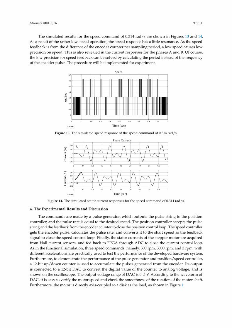
The simulated results for the speed command of 0.314 rad/s are shown in Figures 13 and 14. As
a result of the rather low speed operation, the speed response has a little resonance. As the speed
feedback is from the difference of the encoder counter per sampling period, a low speed causes low
precision on speed. This is also revealed in the current responses for the phases A and B. Of course,
the low precision for speed feedback can be solved by calculating the period instead of the frequency
of the encoder pulse. The procedure will be implemented for experiment.
Time (sec)
Speed
rad/s
ec
Time (sec)
Phase Currents
Ai
Cu
rren
t (A
)C
urr
ent
(A)
Bi
Ai
Bi
Figure 11. The simulated speed response of speed command of 314 rad/s.
Machines 2018, 6, x FOR PEER REVIEW 9 of 15
Figure 11. The simulated speed response of speed command of 314 rad/s.
Figure 12. The simulated stator current responses for the speed command of 314 rad/s.
The simulated results for the speed command of 0.314 rad/s are shown in Figures 13 and 14. As
a result of the rather low speed operation, the speed response has a little resonance. As the speed
feedback is from the difference of the encoder counter per sampling period, a low speed causes low
precision on speed. This is also revealed in the current responses for the phases A and B. Of course,
the low precision for speed feedback can be solved by calculating the period instead of the frequency
of the encoder pulse. The procedure will be implemented for experiment.
Time (sec)
Speed
rad/s
ec
Time (sec)
Phase Currents
Ai
Cu
rren
t (A
)C
urr
ent
(A)
Bi
Ai
Bi
Figure 12. The simulated stator current responses for the speed command of 314 rad/s.
Machines 2018, 6, 56 9 of 14
The simulated results for the speed command of 0.314 rad/s are shown in Figures 13 and 14.As a result of the rather low speed operation, the speed response has a little resonance. As the speedfeedback is from the difference of the encoder counter per sampling period, a low speed causes lowprecision on speed. This is also revealed in the current responses for the phases A and B. Of course,the low precision for speed feedback can be solved by calculating the period instead of the frequencyof the encoder pulse. The procedure will be implemented for experiment.Machines 2018, 6, x FOR PEER REVIEW 10 of 15
Figure 13. The simulated speed response of the speed command of 0.314 rad/s.
Figure 14. The simulated stator current responses for the speed command of 0.314 rad/s.
4. The Experimental Results and Discussion
The commands are made by a pulse generator, which outputs the pulse string to the position
controller, and the pulse rate is equal to the desired speed. The position controller accepts the pulse
string and the feedback from the encoder counter to close the position control loop. The speed
controller gets the encoder pulse, calculates the pulse rate, and converts it to the shaft speed as the
feedback signal to close the speed control loop. Finally, the stator currents of the stepper motor are
acquired from Hall current sensors, and fed back to FPGA through ADC to close the current control
loop. As in the functional simulation, three speed commands, namely, 300 rpm, 3000 rpm, and 3 rpm,
with different accelerations are practically used to test the performance of the developed hardware
system. Furthermore, to demonstrate the performance of the pulse generator and position/speed
controller, a 12-bit up/down counter is used to accumulate the pulses generated from the encoder. Its
output is connected to a 12-bit DAC to convert the digital value of the counter to analog voltage, and
is shown on the oscilloscope. The output voltage range of DAC is 0–5 V. According to the waveform
of DAC, it is easy to verify the motor speed and check the smoothness of the rotation of the motor
shaft. Furthermore, the motor is directly axis-coupled to a disk as the load, as shown in Figure 1.
First, the output of DAC for 300 rpm speed command is shown in Figure 15, where the period
is about 41 ms. Each of one triangle cycles is equal to 1.2868 radians, shown in (8).
rad (8)
The decimal range of the DAC counter is 0–4095, it has total 4096 counters, and the resolution of
encoder is 20,000 p/rev. The motor speed can be obtaiuned by (9):
(9)
Time (sec)
Speed
rad/s
ec
Time (sec)
Phase Currents
Ai
Cu
rren
t (A
)C
urr
ent
(A)
Bi
2868.1220000
4096==
3
1.286831.39 rad/s 299.8 rpm
41 10T
−
= = = =
Figure 13. The simulated speed response of the speed command of 0.314 rad/s.
Machines 2018, 6, x FOR PEER REVIEW 10 of 15
Figure 13. The simulated speed response of the speed command of 0.314 rad/s.
Figure 14. The simulated stator current responses for the speed command of 0.314 rad/s.
4. The Experimental Results and Discussion
The commands are made by a pulse generator, which outputs the pulse string to the position
controller, and the pulse rate is equal to the desired speed. The position controller accepts the pulse
string and the feedback from the encoder counter to close the position control loop. The speed
controller gets the encoder pulse, calculates the pulse rate, and converts it to the shaft speed as the
feedback signal to close the speed control loop. Finally, the stator currents of the stepper motor are
acquired from Hall current sensors, and fed back to FPGA through ADC to close the current control
loop. As in the functional simulation, three speed commands, namely, 300 rpm, 3000 rpm, and 3 rpm,
with different accelerations are practically used to test the performance of the developed hardware
system. Furthermore, to demonstrate the performance of the pulse generator and position/speed
controller, a 12-bit up/down counter is used to accumulate the pulses generated from the encoder. Its
output is connected to a 12-bit DAC to convert the digital value of the counter to analog voltage, and
is shown on the oscilloscope. The output voltage range of DAC is 0–5 V. According to the waveform
of DAC, it is easy to verify the motor speed and check the smoothness of the rotation of the motor
shaft. Furthermore, the motor is directly axis-coupled to a disk as the load, as shown in Figure 1.
First, the output of DAC for 300 rpm speed command is shown in Figure 15, where the period
is about 41 ms. Each of one triangle cycles is equal to 1.2868 radians, shown in (8).
rad (8)
The decimal range of the DAC counter is 0–4095, it has total 4096 counters, and the resolution of
encoder is 20,000 p/rev. The motor speed can be obtaiuned by (9):
(9)
Time (sec)
Speed
rad/s
ec
Time (sec)
Phase Currents
Ai
Cu
rren
t (A
)C
urr
ent
(A)
Bi
2868.1220000
4096==
3
1.286831.39 rad/s 299.8 rpm
41 10T
−
= = = =
Figure 14. The simulated stator current responses for the speed command of 0.314 rad/s.
4. The Experimental Results and Discussion
The commands are made by a pulse generator, which outputs the pulse string to the positioncontroller, and the pulse rate is equal to the desired speed. The position controller accepts the pulsestring and the feedback from the encoder counter to close the position control loop. The speed controllergets the encoder pulse, calculates the pulse rate, and converts it to the shaft speed as the feedbacksignal to close the speed control loop. Finally, the stator currents of the stepper motor are acquiredfrom Hall current sensors, and fed back to FPGA through ADC to close the current control loop.As in the functional simulation, three speed commands, namely, 300 rpm, 3000 rpm, and 3 rpm, withdifferent accelerations are practically used to test the performance of the developed hardware system.Furthermore, to demonstrate the performance of the pulse generator and position/speed controller,a 12-bit up/down counter is used to accumulate the pulses generated from the encoder. Its outputis connected to a 12-bit DAC to convert the digital value of the counter to analog voltage, and isshown on the oscilloscope. The output voltage range of DAC is 0–5 V. According to the waveform ofDAC, it is easy to verify the motor speed and check the smoothness of the rotation of the motor shaft.Furthermore, the motor is directly axis-coupled to a disk as the load, as shown in Figure 1.

Machines 2018, 6, 56 10 of 14
First, the output of DAC for 300 rpm speed command is shown in Figure 15, where the period isabout 41 ms. Each of one triangle cycles is equal to 1.2868 radians, shown in (8).
∆θ =409620000
× 2π = 1.2868 rad (8)
Machines 2018, 6, x FOR PEER REVIEW 11 of 15
The waveform demonstrates that the speed is quite smooth under the proposed vector control
system.
Figure 15. The output of position counter by DAC for the speed command of 300 rpm.
The current responses are shown in Figure 16, where the period is about 4 ms, and phase currents
A and B are in quadrature. The peak-to-peak value of the current is about 1 A.
As the pole pair for the proposed hybrid stepper motor is 50, that is, P = 50. According to (10),
the result is the same as the speed obtained from (9).
(10)
Figure 16. The phase currents A and B of the command of 300 rpm (185 mV/A).
Next, we will demonstrate the performance with the speed command of 3000 rpm using the
vector control, where the current control loop is in the field weaken region as the motor runs beyond
the rated speed. The current responses of Figure 17 are the control results, where the peak-to-peak
current is about 2 A. As the speed of 3000 rpm is beyond the rated speed, the direct component is a
negative value by placing the voltage ahead of the q-axis.
rad 2868.1
220000
4096
=
ms 41
rpm 300004.050
606060=
=
==
sTPP
f
Ai
Bi
refV
Figure 15. The output of position counter by DAC for the speed command of 300 rpm.
The decimal range of the DAC counter is 0–4095, it has total 4096 counters, and the resolution ofencoder is 20,000 p/rev. The motor speed can be obtaiuned by (9):
ω =∆θ
∆T=
1.286841 × 10−3 = 31.39 rad/s = 299.8 rpm (9)
The waveform demonstrates that the speed is quite smooth under the proposed vectorcontrol system.
The current responses are shown in Figure 16, where the period is about 4 ms, and phase currentsA and B are in quadrature. The peak-to-peak value of the current is about 1 A.
Machines 2018, 6, x FOR PEER REVIEW 11 of 15
The waveform demonstrates that the speed is quite smooth under the proposed vector control
system.
Figure 15. The output of position counter by DAC for the speed command of 300 rpm.
The current responses are shown in Figure 16, where the period is about 4 ms, and phase currents
A and B are in quadrature. The peak-to-peak value of the current is about 1 A.
As the pole pair for the proposed hybrid stepper motor is 50, that is, P = 50. According to (10),
the result is the same as the speed obtained from (9).
(10)
Figure 16. The phase currents A and B of the command of 300 rpm (185 mV/A).
Next, we will demonstrate the performance with the speed command of 3000 rpm using the
vector control, where the current control loop is in the field weaken region as the motor runs beyond
the rated speed. The current responses of Figure 17 are the control results, where the peak-to-peak
current is about 2 A. As the speed of 3000 rpm is beyond the rated speed, the direct component is a
negative value by placing the voltage ahead of the q-axis.
rad 2868.1
220000
4096
=
ms 41
rpm 300004.050
606060=
=
==
sTPP
f
Ai
Bi
refV
Figure 16. The phase currents A and B of the command of 300 rpm (185 mV/A).
As the pole pair for the proposed hybrid stepper motor is 50, that is, P = 50. According to (10),the result is the same as the speed obtained from (9).
ω =60 fP
=60
P × Ts=
6050 × 0.004
= 300 rpm (10)

Machines 2018, 6, 56 11 of 14
Next, we will demonstrate the performance with the speed command of 3000 rpm using thevector control, where the current control loop is in the field weaken region as the motor runs beyondthe rated speed. The current responses of Figure 17 are the control results, where the peak-to-peakcurrent is about 2 A. As the speed of 3000 rpm is beyond the rated speed, the direct component is anegative value by placing the voltage Vre f ahead of the q-axis.Machines 2018, 6, x FOR PEER REVIEW 12 of 15
Figure 17. The phase currents A and B of the command of 3000 rpm (185 mV/A).
The position responses for the speed command of 3000 rpm are shown in Figure 18. The motor
speed from the curve shown in Figure 16 is approximately
(10)
The speed can also be verified by Figure 17, which has a period about 400 , which
corresponds to 3000 rpm.
Compared with the results of Figures 15 and 18, their sloping sides are very smooth, that is, the
motor is run under a very stable condition.
Figure 18. The position responses for the speed command of 3000 rpm.
Finally, the low speed condition is performed with the speed command of 3 rpm, the position
and current responses are shown in Figures 19 and 20, respectively. With the position response of
Figure 19, the speed is calculated as follows:
(11)
However, in the low speed range, the speed is calculated by measuring the period of the encoder
pulse instead of the frequency. Furthermore, as the command is from the pulse string generator to
the position controller, once the position error is very close to zero, the speed control loop will be
skipped, and the current command will come directly from the position controller. With those
strategies, we obtained a smooth speed response as in Figure 19, and current response as in Figure
20, where the phase currents are in quadrature.
Ai
Bi
3
1.2868310.07 rad/sec 2960 rpm
Δ 4.15 10T
−
= = = =
μs
ms 15.4
rpm 92.2rad/sec 306.02.4
2868.1===
=
T
Figure 17. The phase currents A and B of the command of 3000 rpm (185 mV/A).
The position responses for the speed command of 3000 rpm are shown in Figure 18. The motorspeed from the curve shown in Figure 16 is approximately
ω =∆θ
∆T=
1.28684.15 × 10−3 = 310.07 rad/s = 2960 rpm (10)
Machines 2018, 6, x FOR PEER REVIEW 12 of 15
Figure 17. The phase currents A and B of the command of 3000 rpm (185 mV/A).
The position responses for the speed command of 3000 rpm are shown in Figure 18. The motor
speed from the curve shown in Figure 16 is approximately
(10)
The speed can also be verified by Figure 17, which has a period about 400 , which
corresponds to 3000 rpm.
Compared with the results of Figures 15 and 18, their sloping sides are very smooth, that is, the
motor is run under a very stable condition.
Figure 18. The position responses for the speed command of 3000 rpm.
Finally, the low speed condition is performed with the speed command of 3 rpm, the position
and current responses are shown in Figures 19 and 20, respectively. With the position response of
Figure 19, the speed is calculated as follows:
(11)
However, in the low speed range, the speed is calculated by measuring the period of the encoder
pulse instead of the frequency. Furthermore, as the command is from the pulse string generator to
the position controller, once the position error is very close to zero, the speed control loop will be
skipped, and the current command will come directly from the position controller. With those
strategies, we obtained a smooth speed response as in Figure 19, and current response as in Figure
20, where the phase currents are in quadrature.
Ai
Bi
3
1.2868310.07 rad/sec 2960 rpm
Δ 4.15 10T
−
= = = =
μs
ms 15.4
rpm 92.2rad/sec 306.02.4
2868.1===
=
T
Figure 18. The position responses for the speed command of 3000 rpm.
The speed can also be verified by Figure 17, which has a period about 400 µs, which correspondsto 3000 rpm.
Compared with the results of Figures 15 and 18, their sloping sides are very smooth, that is,the motor is run under a very stable condition.
Finally, the low speed condition is performed with the speed command of 3 rpm, the position andcurrent responses are shown in Figures 19 and 20, respectively. With the position response of Figure 19,the speed is calculated as follows:
ω =∆θ
∆T=
1.28684.2
= 0.306 rad/s = 2.92 rpm (11)

Machines 2018, 6, 56 12 of 14
Machines 2018, 6, x FOR PEER REVIEW 13 of 15
In viewing those experimental results, one has demonstrated the performance for high, medium,
and low speed commands, and the performances for different position/speed requirements are fitted
to those desired through the closed-loop position and speed control.
Figure 19. The position responses for the speed command of 3 rpm.
Figure 20. The current responses for the speed command of 3 rpm (185 mV/A).
The position experimental results are shown in Figures 21–23. The position command is to rotate
the motor with the trapezoidal velocity profile as shown in Figure 21, where the acceleration and
deceleration are and , respectively, and the maximum velocity is 300
rpm. The total rotation is 30 revolutions, which is equal to 600,000 counts from the encoder. The DAC
is used to convert the digital position and velocity signals to analog voltage with the appropriate ratio,
as shown in Figures 21 and 22. To verify the end point value of the position counter, a 9-bit logical
analyzer is used. The stepper motor of the experiment has pole pair 50 and 20,000 p/rev encoder, in
which one electrical cycle is equal to 400 encoder pulses. Thus, we create a 400-step counter, which
needs 9 bits in order to receive the pulses sent from the encoder, will be cleared (the value is 00000000)
initially. According to Figure 23, the binary value of the 9-bit counter is 000000000 at the position
marked “starting”. With the control of position controller and the pulse string generator, the value at
the end point is also 000000000, that is, in this experiment, the final position stops exactly at the
command.
s 2.4
Ai
Bi
231.4 rad/s 231.4 rad/ s−
Figure 19. The position responses for the speed command of 3 rpm.
Machines 2018, 6, x FOR PEER REVIEW 13 of 15
In viewing those experimental results, one has demonstrated the performance for high, medium,
and low speed commands, and the performances for different position/speed requirements are fitted
to those desired through the closed-loop position and speed control.
Figure 19. The position responses for the speed command of 3 rpm.
Figure 20. The current responses for the speed command of 3 rpm (185 mV/A).
The position experimental results are shown in Figures 21–23. The position command is to rotate
the motor with the trapezoidal velocity profile as shown in Figure 21, where the acceleration and
deceleration are and , respectively, and the maximum velocity is 300
rpm. The total rotation is 30 revolutions, which is equal to 600,000 counts from the encoder. The DAC
is used to convert the digital position and velocity signals to analog voltage with the appropriate ratio,
as shown in Figures 21 and 22. To verify the end point value of the position counter, a 9-bit logical
analyzer is used. The stepper motor of the experiment has pole pair 50 and 20,000 p/rev encoder, in
which one electrical cycle is equal to 400 encoder pulses. Thus, we create a 400-step counter, which
needs 9 bits in order to receive the pulses sent from the encoder, will be cleared (the value is 00000000)
initially. According to Figure 23, the binary value of the 9-bit counter is 000000000 at the position
marked “starting”. With the control of position controller and the pulse string generator, the value at
the end point is also 000000000, that is, in this experiment, the final position stops exactly at the
command.
s 2.4
Ai
Bi
231.4 rad/s 231.4 rad/ s−
Figure 20. The current responses for the speed command of 3 rpm (185 mV/A).
However, in the low speed range, the speed is calculated by measuring the period of the encoderpulse instead of the frequency. Furthermore, as the command is from the pulse string generatorto the position controller, once the position error is very close to zero, the speed control loop willbe skipped, and the current command will come directly from the position controller. With thosestrategies, we obtained a smooth speed response as in Figure 19, and current response as in Figure 20,where the phase currents are in quadrature.
In viewing those experimental results, one has demonstrated the performance for high, medium,and low speed commands, and the performances for different position/speed requirements are fittedto those desired through the closed-loop position and speed control.
The position experimental results are shown in Figures 21–23. The position command is to rotatethe motor with the trapezoidal velocity profile as shown in Figure 21, where the acceleration anddeceleration are 31.4 rad/s2 and −31.4 rad/s2, respectively, and the maximum velocity is 300 rpm.The total rotation is 30 revolutions, which is equal to 600,000 counts from the encoder. The DACis used to convert the digital position and velocity signals to analog voltage with the appropriateratio, as shown in Figures 21 and 22. To verify the end point value of the position counter, a 9-bitlogical analyzer is used. The stepper motor of the experiment has pole pair 50 and 20,000 p/revencoder, in which one electrical cycle is equal to 400 encoder pulses. Thus, we create a 400-step counter,which needs 9 bits in order to receive the pulses sent from the encoder, will be cleared (the value is00000000) initially. According to Figure 23, the binary value of the 9-bit counter is 000000000 at theposition marked “starting”. With the control of position controller and the pulse string generator,

Machines 2018, 6, 56 13 of 14
the value at the end point is also 000000000, that is, in this experiment, the final position stops exactlyat the command.Machines 2018, 6, x FOR PEER REVIEW 14 of 15
Figure 21. The trapezoidal velocity profile (70 rpm/div).
Figure 22. The position response (5 rev/div).
Figure 23. The logical analyzer output for position response.
5. Conclusions
In this paper, we have demonstrated the design of stepper motor position/speed/current
controllers with different speed commands to verify the performances when the control system is
completely constructed by FPGA and ADC as an embedded system. With the current vector control,
and considering the field weaken region operation, we have successfully made the stepper motor
operate in low, medium, and high speeds with load condition. As a result of the design of the closed-
loop control for position and speed, the stepper motor drive has been presented to be able to be used
in a wide range of speed applications, such as those shown in Figures 21–23. This system can be
300 rpm
30 rev
MSB
LSB
starting end point
Figure 21. The trapezoidal velocity profile (70 rpm/div).
Machines 2018, 6, x FOR PEER REVIEW 14 of 15
Figure 21. The trapezoidal velocity profile (70 rpm/div).
Figure 22. The position response (5 rev/div).
Figure 23. The logical analyzer output for position response.
5. Conclusions
In this paper, we have demonstrated the design of stepper motor position/speed/current
controllers with different speed commands to verify the performances when the control system is
completely constructed by FPGA and ADC as an embedded system. With the current vector control,
and considering the field weaken region operation, we have successfully made the stepper motor
operate in low, medium, and high speeds with load condition. As a result of the design of the closed-
loop control for position and speed, the stepper motor drive has been presented to be able to be used
in a wide range of speed applications, such as those shown in Figures 21–23. This system can be
300 rpm
30 rev
MSB
LSB
starting end point
Figure 22. The position response (5 rev/div).
Machines 2018, 6, x FOR PEER REVIEW 14 of 15
Figure 21. The trapezoidal velocity profile (70 rpm/div).
Figure 22. The position response (5 rev/div).
Figure 23. The logical analyzer output for position response.
5. Conclusions
In this paper, we have demonstrated the design of stepper motor position/speed/current
controllers with different speed commands to verify the performances when the control system is
completely constructed by FPGA and ADC as an embedded system. With the current vector control,
and considering the field weaken region operation, we have successfully made the stepper motor
operate in low, medium, and high speeds with load condition. As a result of the design of the closed-
loop control for position and speed, the stepper motor drive has been presented to be able to be used
in a wide range of speed applications, such as those shown in Figures 21–23. This system can be
300 rpm
30 rev
MSB
LSB
starting end point
Figure 23. The logical analyzer output for position response.
5. Conclusions
In this paper, we have demonstrated the design of stepper motor position/speed/currentcontrollers with different speed commands to verify the performances when the control systemis completely constructed by FPGA and ADC as an embedded system. With the current vectorcontrol, and considering the field weaken region operation, we have successfully made the stepper

Machines 2018, 6, 56 14 of 14
motor operate in low, medium, and high speeds with load condition. As a result of the design of theclosed-loop control for position and speed, the stepper motor drive has been presented to be able tobe used in a wide range of speed applications, such as those shown in Figures 21–23. This systemcan be combined into a complete motion control system, which includes the motion controller andmotor drive.
Author Contributions: Conceptualization, C.-K.L. and J.-S.C.; Methodology, C.-K.L. and J.-S.C.; Software, J.-S.C.and C.-C.T.; Validation, J.-S.C. and C.-C.T.; Formal Analysis, C.-K.L., J.-S.C., and C.-C.T.; Investigation, C.-K.L.,J.-S.C., and C.-C.T.; Resources, C.-K.L.; Data Curation, J.-S.C. and C.-C.T.; Writing—Original Draft Preparation,C.-K.L., J.-S.C., and C.-C.T.; Writing—Review & Editing, C.-K.L. and J.-S.C.; Visualization, C.-K.L., J.-S.C., andC.-C.T.; Supervision, C.-K.L.; Project Administration, C.-K.L.; Funding Acquisition, C.-K.L.
Funding: This research was funded by [Ministry of Science and Technology of Taiwan] grant number [MOST106-2622-E-167-008-CC3].
Conflicts of Interest: The authors declare no conflict of interest.
References
1. Lu, W.; Wang, Q.; Ji, K.; Dong, H.; Lin, J.; Qian, J. Research on Closed-loop Drive System of Two-phaseHybrid Step Motor Based on SVPWM. In Proceedings of the IEEE Vehicle Power and Propulsion Conference(VPPC), Hangzhou, China, 17–20 October 2016.
2. Crnoˇsija, P.; Kuzmanovic, B.; Ajdukovic, S. Microcomputer Implementation of Optimal Algorithms forClosed-Loop Control of Hybrid Stepper Motor Drives. IEEE Trans. Ind. Electron. 2000, 47, 1319–1325.
3. Le, K.M.; van Hoang, H.; Jeon, J.W. An Advanced Closed-Loop Control to Improve the Performance ofHybrid Stepper Motors. IEEE Trans. Power Electron. 2017, 32, 7244–7255. [CrossRef]
4. Chaurasiya Rohit, B.; Mukesh, D.; Patil, D.S.; Kadam, A. FPGA Implementation of SVPWM ControlTechnique for Three Phase Induction Motor Drive Using Fixed Point Realization. In Proceedings of theInternational Conference on Circuits, Systems, Communication and Information Technology Applications(CSCITA), Mumbai, India, 4–5 April 2014; pp. 93–98.
5. Kung, Y.-S.; Tsai, M.-H. FPGA-Based Speed Control IC for PMSM Drive with Adaptive Fuzzy Control.IEEE Trans. Power Electron. 2007, 22, 2476–2486. [CrossRef]
6. Quynh, N.V.; Kung, Y.-S. FPGA-Realization of Fuzzy Speed Controller for PMSM Drives without PositionSensor. ICCAIS 2013, 278–282. [CrossRef]
7. Kenneth, W.H.; Tsui, N.C. Cheung, Novel Modeling and Damping Technique for Hybrid Stepper Motor.IEEE Trans. Ind. Electron. 2009, 56, 202–211.
8. Kocur, M.; Kozak, S.; Dvorscak, B. Design and Implementation of FPGA—Digital Based PID Controller.In Proceedings of the 15th International Carpathian Control Conference (ICCC), Ostrava, Czech Republic,28–30 May 2014; pp. 233–236.
9. Siwakoti, Y.P.; Town, G.E. Design of FPGA-Controlled Power Electronics and Drives Using MATLABSimulink. In Proceedings of the IEEE/ECCE Asia, Melbourne, Australia, 3–6 June 2013; pp. 571–577.
10. Lai, C.-K.; Tsao, Y.-T.; Tsai, C.-C. Modeling, Analysis, and Realization of Permanent Magnet SynchronousMotor Current Vector Control by MATLAB/Simulink and FPGA. Machines 2017, 5, 26. [CrossRef]
11. Stumpf, A.; Elton, D.; Devlin, J.; Lovatt, H. Benefits of an FPGA based SRM controller. In Proceedings of theIEEE 9th Conference on Industrial Electronics and Applications (ICIEA), Hangzhou, China, 9–11 June 2014;pp. 12–17.
12. Horvat, R.; Jezernik, K.; Curkovic, M. An Event-Driven Approach to the Current Control of a BLDC MotorUsing FPGA. IEEE Trans. Ind. Electron. 2014, 61, 3719–3726. [CrossRef]
13. Lai, C.-K.; Chien, W.-N.; Tsai, S.-L.; Tsao, Y.-T. The Modelling, Simulation and Hardware Implementation forFPGA-based Stepping Motor Motion Drive. Int. J. Comput. Consum. Control 2016, 5, 33–47.
© 2018 by the authors. Licensee MDPI, Basel, Switzerland. This article is an open accessarticle distributed under the terms and conditions of the Creative Commons Attribution(CC BY) license (http://creativecommons.org/licenses/by/4.0/).


![[NCKU] Simulation and Verification with Altera FPGA](https://img.dokumen.tips/doc/110x75/55295cbf550346522e8b4745/ncku-simulation-and-verification-with-altera-fpga.jpg)