Embed Size (px)
Citation preview

TRANSPORT PROBLEMS 2018 Volume 13 Issue 1 PROBLEMY TRANSPORTU DOI: 10.21307/tp.2018.13.1.6
Keywords: Reactive power; power factor; AC catenary; capacitive compensation; capacitor banks
Lionginas LIUDVINAVIČIUS
Vilnius Gediminas Technical University, Department of Railway Transport J. Basanavičius str. 28, LT-03224 Vilnius, Lithuania Corresponding author. E-mail: [email protected]
THE METHODS OF REACTIVE POWER COMPENSATION IN THE 25 kV, 50 Hz CONTACT NETWORK
Summary. The article analyses theoretical and practical solutions of reactive power
compensation in the power grid of 25 kV, 50 Hz of the catenary. The article presents theoretical and practical studies (by providing circuits for connecting capacitor banks, structural circuits diagrams for the automatic control reactive power level, and calculating the parameters of capacitor banks) for the compensation of reactive power.
1. INTRODUCTION
It is only lately that modern solutions have been applied in the area of reactive power compensation to not only reduce the costs for the use of reactive power but also to improve the quality of the energy system. By compensating the reactive power in the power grid and filtering the harmonics of undesirable currents, higher quality of electric power in terms of voltage is ensured, and the losses of voltage and power are reduced [1, 2]. The aim of load compensation is to boost the power factor of the system, to support the real power drawn from the system, to regulate the voltage, and to remove current harmonics [3]. Reactive power compensation is one of the most effective ways to reduce consumed electric energy and improve power quality. The examples of how reactive power compensation can improve the technical-and-economic indexes of an industrial power grid are as follows: [20].
• reduce cost and generate higher revenue for the customer, • reduce network losses, • avoid penalty charges from utilities for excessive consumption of reactive power, • increase system capacity and save costs on new installations, • improve system power factor, • increase power availability, and • improve voltage regulation in the network. Nowadays, static VAR compensators (SVCs) and static synchronous compensators (STATCOMs)
are the most useful devices to control the dynamic reactive power level in the industrial grid [21]. This article presents some methods, showing the potential use of dynamic reactive power compensation via the series compensation devices SCB (capacitors banks) located in 25 kV AC catenary the arms of A, B phases and in the line of return current (see Fig. 6a). Having analysed the supply system of alternating current 25 kV AC catenary, the author proposes to locate the series compensation devices SCB (capacitors banks) in the arms of A, B phases and in the line of return current (see Fig. 6a) and methods for dynamic reactive power value automatic control.

60 L. Liudvinavičius
2. COMPENSATION OF REACTIVE POWER BY USING SYCHRONOUS MACHINES
Regulation of reactive power of synchronous generator. The reactive power of synchronous
generator is regulated by changing its exciting current [4]. Let us say that a synchronous generator is operating connected to the power system, where the capacity of the turbines rotating it is constant, the active power of the generator is P = 3UIcosφ = const. By changing the exciting current of the synchronous generator If, its EMF is changing Ef = CEФf n, hence the maximum generator active capacity Pmax = 3UIEf//X is changing. Fig. 1a illustrates three angular characteristics of the generator. The phasor diagrams of the generator armature winding for these three cases have been provided in Fig. 1 c, d, and e. The voltage of the synchronous generator connected to the energy system remains constant by changing the exciting current. “U” curves for a synchronous machine (a) and a phasor diagram of a synchronous compensator armature winding (b) are provided in Fig. 2. The variations of I with excitation are known as “U” curves because of their shape. For the same mechanical load, the armature current varies with field excitation over a wide range and therefore causes the power factor also to vary respectively.
Main designation of the diagram in Fig. 1, 2: If – exciting current; I – load current; U – voltage of power supply; Θ1 – the synchronous machine angle between U and Ef vectors; φ2 – the angle between I and U vectors; and X – reactance.
a) b) c)
d) e)
Fig. 1. Angular characteristics of a synchronous generator (a), currents and electromotive force EMF vector hodographs (b) and armature winding current phasor diagrams (c, d, e), with different values of exciting current
When over-excited, the motor runs with leading power factor (and supplies vars to the grid) and
when under-excited with a lagging power factor (and absorbs VARs from the grid). In between, the power factor is unity (see Fig. 2). The minimum armature current corresponds to
the point of unity power factor (voltage and current in phase).

The methods of reactive power compensation in… 61.
a) b)
Fig. 2. “U” curves for a synchronous machine (a) and a phasor diagram of a synchronous compensator armature winding (b)
Regulation of reactive power of synchronous condenser. In electrical engineering, a
synchronous condenser (sometimes called a synchronous capacitor or synchronous compensator) is a device identical to a synchronous motor, whose shaft is not connected to anything but spins freely. Its purpose is not to convert electric power to mechanical power or vice versa but to adjust conditions on the electric power transmission grid. Its field is controlled by a voltage regulator to either generate or absorb reactive power as needed to adjust the grid’s voltage or to improve the power factor. However, synchronous machines have higher energy losses than static capacitor banks [5]. Most synchronous condensers connected to electrical grids are rated between 20 MVAR (megavars) and 200 MVAR, and many are hydrogen cooled. There is no explosion hazard as long as the hydrogen concentration is maintained above 70%, typically above 91% [6].
3. COMPENSATION OF REACTIVE POWER BY USING CAPACITORS
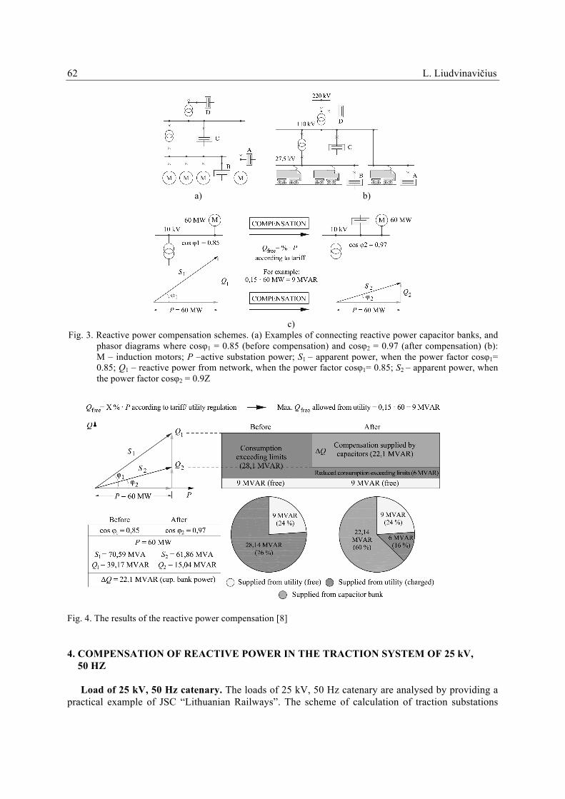
Capacitive compensation. Depending on the method of connecting capacitors with regard to loading (in parallel or in series), shunt or series capacitive compensation is singled out [7]. A typical reactive power compensation scheme is used for industrial power system (Fig. 3a). The author of the proposed reactive power compensation scheme for 25 kV, 50 Hz traction system (Fig. 1b) examples of connecting reactive power capacitor banks, phasor diagrams where cosφ1 = 0.85 (before compensation) and cosφ2 = 0.97 (after are provided in Fig. 3c. Possible locations of the capacitor bank offered by company ABB have been provided in Fig. 3a). The location is primarily determined by the reason for compensation – A: Direct Compensation. B: Group Compensation. C: Central Compensation at low voltage (LV) side. D: Central Compensation at high voltage (HV) side [8]. The power triangle of an installation running at low cost and where the load of the transformer is close to full. The power triangle of the same installation where power factor correction has been applied reduces load on the transformer / releases capacity for additional loads [9].
The technical solutions of company ABB reactive power compensation and the expected financial results have been provided in Fig. 4.
Fig. 4 illustrates phasor diagrams where the power factor cosφ1, with active power of 60 MW, is increased from 0.85 to 0.97. Calculations of the capacitor bank reactive power and other related technical and financial calculations are provided below.
62 L. Liudvinavičius
a) b)
c)
Fig. 3. Reactive power compensation schemes. (a) Examples of connecting reactive power capacitor banks, and phasor diagrams where cosφ1 = 0.85 (before compensation) and cosφ2 = 0.97 (after compensation) (b): M – induction motors; P –active substation power; S1 – apparent power, when the power factor cosφ1= 0.85; Q1 – reactive power from network, when the power factor cosφ1= 0.85; S2 – apparent power, when the power factor cosφ2 = 0.9Z
Fig. 4. The results of the reactive power compensation [8]
4. COMPENSATION OF REACTIVE POWER IN THE TRACTION SYSTEM OF 25 kV, 50 HZ
Load of 25 kV, 50 Hz catenary. The loads of 25 kV, 50 Hz catenary are analysed by providing a
practical example of JSC “Lithuanian Railways”. The scheme of calculation of traction substations

The methods of reactive power compensation in… 63.
(TS), catenary parameters and reactive power Q consumption of JSC “Lithuanian Railways” for electric traction in the period between 2010 and 2015 have been provided in Fig. 5. [19]
a) b)
Fig. 5. The scheme of calculation of traction substations, catenary parameters (a) and reactive power Q consumption of JSC “Lithuanian Railways” for electric traction in the period between 2010 and2015 (b): ICat. – catenary current; I1, I2 I3 – electric traction vehicle current; L1, L2, L3 – distance between traction substation and electric train; U1 – catenary voltage; PETV1, PETV2, PETV3 – electric traction vehicle active power; S – apparent power; ITS. – traction substation current; ΔUL – catenary circuit voltage losses; ΔUB – rail circuit voltage losses
Having analysed the supply system of alternating current 25 kV AC catenary, the author proposed
to locate the series compensation devices SCB (capacitors banks) in the arms of A, B phases and in the line of return current (see Fig. 6a). A principal scheme of a reactive power series compensation (a), an equivalent scheme and a diagram of potentials (b), where SCB is located in a single arm, is provided in Fig. 6b). Main designation of the diagram in Fig. 6: 1– electric traction rolling stock ETV; Хс – SCB capacity resistance in the feeder (in the arms of A and B phases); ХСр – SCB capacity resistance in the line of return current; U1 – voltage of power supply; U2 – SCB voltage in the connection point; U2с – voltage after connection of SCB; I2 – load current, Rs and Xs – active and reactive circuit resistance from the power supply to the point of connecting SCB; Хc – resistance of capacity capacitors SCB; φ2 – the angle between I2 and U2, where SCB is disconnected (Хс = 0) and, where SCB is connected (Хс ≠ 0).
a) b)
Fig. 6. The author proposes a principal scheme of a reactive power series compensation (a) and an equivalent scheme and a potential diagram (b)

64 L. Liudvinavičius
By connecting the capacitor devices to the circuit, the power factor соs φ2 of the series compensation devices SCB may be increased from 0.88 to 0.98 (see Fig. 6).
5. AUTOMATIC CONTROL OF THE PARAMETERS OF THE COMPENSATION EQUIPMENT
The schemes of compensation of reactive power equipment connection and automatic control are
provided in Fig. 7. For the dynamic reactive power value control of the compensation equipment parameter (C value of the capacity bank), the author proposes to connect an electronic device made of thyristors connected in series and inverse-parallel thyristor valves. By sending respective opening signals to the thyristor gates, the value of the reactive power consumed (in the straightforward direction) and the value of the compensatory reactive power (in the inverse direction) may be controlled [11]. The author’s proposed use of simplified automatic control schemes of the series compensation devices SCB (capacitors banks), reactor connection, and thyristor connected reactive power compensation (TSC) (capacitive and inductive) have been provided in Fig. 7 [19]. In the middle part of the schemes (see Fig. 7), a phasor diagram of the reactive power compensation is provided, where the capacitor bank and the reactor are connected consistently. Control system designing with a reactive control loop was synthesized on the basis of the system – the supply system of alternating current 25 kV AC catenary shown in Fig. 7. To investigate a reactive power compensation mode, it is necessary to perform synthesis of the new control system and control system of the electronic device made of thyristors connected in series and inverse-parallel thyristor valves. Control system is two-loop and consists of two-channel current control systems reactive power control loop and a load control system. It allows for a separate regulation of the active id and reactive iq current components. Operating conditions of the main circuit diagram have been provided in Fig. 7 by using current sensor CT and control blocks signals.
Fig. 7. The author proposed simplified and automatic control of reactive power compensation scheme: CT –
current sensor (current transformer CT); ΔIQ – reactive current deviation; L – reactor inductance; Xc – capacitors bank capacity resistance; Y – control signal; T1-T2 – thyristors; Ic – reactive power compensation current; A, B, C – phases
Static synchronous compensator (STATCOM) and static VAR compensator (SVC): most
common SVCs are as follows: thyristor-controlled reactor (TCR), where the reactor is connected in series with a bidirectional thyristor valve. The thyristor valve is phase-controlled. Equivalent reactance varies continuously. Thyristor-switched reactor (TSR): it is the same as TCR but thyristor is either in

The methods of reactive power compensation in… 65.
zero- or full- conduction. Equivalent reactance is varied in stepwise manner. Thyristor-switched capacitor (TSC): here the capacitor is connected in series with a bidirectional thyristor valve. Thyristor is in either zero- or full-conduction. Equivalent reactance is varied in stepwise manner. Mechanically switched capacitor (MSC): here the capacitor is switched by circuit-breaker. It aims at compensating steady-state reactive power. It is switched only a few times a day.
Examples of FACTS for series compensation (schematic). Thyristor-controlled series capacitor (TCSC): a series capacitor bank is shunted by a thyristor-controlled reactor [12]. Thyristor-controlled series reactor (TCSR): a series reactor bank is shunted by a thyristor-controlled reactor. Thyristor-switched series capacitor (TSSC): a series capacitor bank is shunted by a thyristor-switched reactor. Thyristor-switched series reactor (TSSR): a series reactor bank is shunted by a thyristor-switched reactor.
Static reactive power compensators. Prior to the invention of the static reactive power compensators, power factor compensation was used to preserve large rotating machines such as synchronous condensers or switched capacitor banks. [13]. The thyristor-controlled reactor (TCR) and thyristor-controlled capacitor (TSC) are a set of electrical devices for providing fast-operating reactive power on high-voltage electricity transmission networks [13, 14]. With the use of phase-control thyristors (see. Fig. 8), the thyristor-controlled reactor (TCR) may be variably switched into the circuit and so as to provide a continuously variable MVAR injection (or absorption) to the electrical network [15]. In this electrical scheme configuration, coarse voltage control is provided by the capacitors. The thyristor-controlled reactor (TCR) and thyristor-controlled capacitor (TSC) are there to provide smooth control [15]. Reactive power compensators should regulate the voltage, power factor and harmonics and stabilize the system [16]. Circuit diagram of reactive power static compensator and the schemes of connection and control of reactive power series compensation devices SCB are provided in Fig. 8.
a) b)
Fig. 8. Circuit diagram of reactive power static compensator (a) and the schemes of connection and control of reactive power series compensation devices SCB (b): IA, IB, IC – reactive power static compensator phases currents; 1-6 – thyristors; 1‘- 6‘ – diodes; Id – rectified current; A, B, C – phases [17]
Research results. The calculated 25 kV, 50 Hz alternating current catenary feeder system
parameters before compensation and after compensation are provided in Table 1.

66 L. Liudvinavičius
Table 1. Definition: P –active traction substation power; S1 – apparent power, when the power factor cosφ1= 0.85; Q1 – reactive power from network, when the power factor cosφ1= 0.85; S2 – apparent power, when the power factor cosφ2 = 0.97; ΔQc – reactive power compensation (supplied by capacitors).
Table 1
The calculated 25 kV, 50 Hz alternating current catenary system parameters before compensation and after compensation
Before compensation After compensation
cosφ1= 0.85 cosφ2 = 0.97 P = 20 MW
11
20 23,53 MVAcos 0,85PSϕ
= = =
φ1 = 31.76° 12
20 20,6 MVAcos 0,97PSϕ
= = = φ2 = 14.07°
1 1 20 0,62 12,4 MVARQ P tgϕ= ⋅ = ⋅ = 2 2 20 0,25 5 MVARQ P tgϕ= ⋅ = ⋅ = Capacitor bank reactive power:
1 2 12,4 5 7,4 MVARcQ S SΔ = − = − = The diagram illustrating the compensation of the reactive power and capacitor bank schemes is
provided in Fig. 9. The diagram illustrates 25 kV, 50 Hz the parameters of alternating current in the catenary feeder before compensation and after compensation that were produced after the implementation of the authors solutions, that is after installing in the 110/27.5/10 kV traction substation 7.4 MVAR reactive power capacitor banks SCB. For the creation of 7.4 MVAR reactive power capacitor bank, fuseless units of company ABB (12 – 25 kV) may be used. Unit voltage range is 300 – 1200 kVAR (50 Hz).
a) b)
Fig. 9. A diagram illustrating compensation of reactive power (a) and the schemes of capacitor bank (b)
For compensation of reactive power, high-voltage capacitors are used [18, 19].
6. CONCLUSIONS 1. The new reactive power compensation method in the supply system of alternating current 25 kV
AC catenary grid via the series compensation devices SCB (capacitors banks) located in 25 kV, 50 Hz catenary the arms of A, B phases and in the line of return current has been proposed.

The methods of reactive power compensation in… 67.
2. It can be implemented to correct a power factor or compensate static or dynamic reactive power. 3. A level of compensated reactive power should be calculated in accordance with load impedance
diagrams and parameters of the 25 kV grid side. 4. In case of 25 kV, 50 Hz, the average power factor of contact network feeder system is cosφ = 0.8. 5. From the calculations it was established that to increase the power factor cosφ from 0.85 to 0.97 of
25 kV, 50 Hz contact network feeder system power cosφ in the traction substation, 7.4 MVAR reactive power capacitors have to be equipped.
6. To increase 25 kV, 50 Hz contact network feeder capacity factor cosφ, synchronous capacitors or capacitor banks may be used.
7. To compensate the reactive power of 25 kV, 50 Hz contact network feeder system, synchronous capacitors or capacitor banks may be used.
8. Synchronous capacitors are electric machines, operating in a generator mode, and they are more suitable for symmetric electric energy supply systems.
9. A 25 kV, 50 Hz contact network supply system is asymmetric, that is, the load of the phases is not equal, hence it is difficult to use synchronous capacitors in a contact network of 25 kV, 50 Hz for the compensation of reactive power.
10. Upon installation in a 110/27.5/10 kV traction substation 7.4 MVAR reactive power capacitor banks, and using the author’s methods for dynamic reactive power value automatic control, cosφ1= 0.85 increased to cosφ2= 0.97.
11. Static reactive power compensators are more expensive than mechanically switched capacitors. 12. Static reactive power compensators are used to provide support for fast changes and the
mechanically switched capacitors to provide steady-state VARs. 13. Optimally designed compensation systems that take into account the requirements of the
equipment and systems to be compensated reduce energy costs by complying with the contractually agreed power factor, enable the planned connection of consumers with a high level of load fluctuation, reduce losses in equipment in customer systems such as transformers and cables as well as in the transmission and distribution network of the network operator, stabilize public and industrial networks by reducing total harmonic distortion, and sustainably reduce CO2 emissions.
References 1. IEC 61000-2-4 Ed. 2.0 Bilingual, Electromagnetic compatibility (EMC) - Part 2-4: Environment -
Compatibility levels in industrial plants for low-frequency conducted disturbances. 2. Energy Efficiency by Power Factor Correction. Information of the ZVEI Power Capacitors
Division. April, 2008. 3. D-A-CH-CZ. Technical Rules for the Assessment of Network Disturbances basic guideline 2007
and supplement on high-voltage power 2012. 4. Masiokas, S. Elektrotechnika. Kaunas: Candela. 1994. 431 p. 5. Weedy, B.M. Electric Power Systems Second Edition. John Wiley and Sons, London, 1972. 149 p. 6. Fink, D. & Beaty, W. (eds.) Standard Handbook for Electrical Engineers Eleventh Edition,
McGraw Hill, 1978. 2144 p. 7. Hammad & Roesle, B. New roles for static Var compensators in transmission systems. Brown
Boveri Rev. Jun. 1986. Vol. 73. P. 314-320. 8. Grünbaum, R. & Halonen, M. & Rudin, S. Power factor, ABB static vars compensator stabilizes
Namibian grid voltage. ABB Rev. 2003. No. 2. P. 43-48. 9. Bonnard, G. The problems posed by electrical power supply to industrial installations. Proc. IEE
Part B. 1985. Vol. 132. No. 6. P. 335-340. 10. Gyugyi, L. & Otto, R. & Putman, T. Principles and applications of static, thyristor-controlled
shunt compensators. IEEE Trans. Power App. Syst. 1980. Vol. PAS-97. No. 5. P. 1935-1945.

68 L. Liudvinavičius
11. Gyugyi, L. Reactive power generation and control by thyristor circuits. IEEE Trans. Ind. Appl. 1979. Vol. IA-15. No. 5. P. 521-532.
12. Grünbaum, R. & Petersson, Å. & Thorvaldsson, B. FACTS, improving the performance of electrical grids. ABB Rev. Mar. 2003. P. 11-18.
13. Ryan, H.M. High Voltage Engineering and Testing. IEE. 2001. P. 160-161. 14. De Kock, J. & Strauss, C. Practical Power Distribution for Industry. Elsevier. 2004. P. 74-75. 15. Deb, A. K. Power Line Ampacity System. CRC Press. P. 169-171. 16. Dixon, J. & Morán, L. A clean four-quadrant sinusoidal power rectifier, using multistage
converters for subway applications. IEEE Trans. Ind. Electron. 2005. Vol. 52. No. 3. P. 653-661. 17. Frank, H. & Ivner, S. Thyristor-controlled shunt compensation in power networks. ASEA J. 1981.
Vol. 54. P. 121-127. 18. EN 50160:2007. General Safety Recommendations for Power Capacitors. “Voltage
characteristics of electricity supplied by public distribution networks”. 19. Liudvinavičius, L. Compensation of Reactive Power of AC Catenary System. Procedia
Engineering. 10th International Scientific Conference Transbaltica 2017: Transportation Science and Technology. 2017. P. 185-197.
20. Zhong, J., et al. Toward a competitive market for reactive power. IEEE Trans. on Power Systems. 2002. Vol. 17. No. 4. P. 1206-1215.
21. Cai, H. et al. The comparison, study and proposal for China's reactive power pricing policy. In: Proc. China International Conference on Electricity Distribution (CICED). IEEE. Sept. 2012.
Received 11.12.2016; accepted in revised form 09.03.2017


![Reactive Power Compensation[1]](https://img.dokumen.tips/doc/110x75/577ccf3f1a28ab9e788f40c0/reactive-power-compensation1.jpg)

