Embed Size (px)
Citation preview

- 42 -
THE MECHANICAL EQUIVALENT OF HEAT
THE MECHANICAL EQUIVALENT OF HEAT LYou may find the complete guide sheet at http://faraday.physics.utoronto.ca/IYearLab/mechequ.pdf
This is the classic experiment, first performed in 1847 by James Joule, which led to our modern view that mechanical work and heat are different aspects of the same quantity, energy. This experiment related the two concepts and provided a connection between the joule, defined in terms of mechanical variables (work, kinetic energy, potential energy, etc.), and the calorie, defined in terms of temperature increases of water. Contemporary SI units do not distinguish between heat energy and mechanical energy, so that heat is also measured in joules. Thus this experiment now takes on the significance of providing a measurement of the specific heat of water in joules per degree per kilogram. In this experiment, work is done by the rubbing of two cones, which raises the temperature of a known amount of water (along with the cones, stirrer, thermometer, etc, which are collectively called the addenda).The ratio of the mechanical work done (W) to the heat which has passed to the water plus addenda (Q) determines J = W/Q. D. Halliday, R. Resnick, and J. Walker. Fundamentals of Physics, 6th edition. Wiley, 2003. E. Hecht. Physics (Calculus). Brooks/Cole, 1996.
- 43 -
DC CIRCUITS
DC CIRCUITS
REFERENCES
D. Halliday, R. Resnick, and J. Walker. Fundamentals of Physics, 6th edition. Wiley, 2003. L. C. McDermott. Physics by Inquiry. Wiley, 1996. Specifications on instruments. Available on the lab computer Faraday. Circuit Wiring Techniques of this Lab Manual. Commonly Used Instruments: The Multimeter of this Lab Manual. OBJECTIVES
This lab will give you experience in - planning and wiring simple circuits, - using digital readout equipment, - measuring currents and voltages associated with specific components in a DC circuit, and - combining resistors in series and parallel. You will have available to you light bulbs, a battery, a source of variable voltage, a box with unknown resistors, meters to measure voltage and current, and wires.
Some electrical terms Charge carriers are charged particles (electrons), which are forced to move in electric circuits by applied electric forces. The force between two charges gives the value of an electron charge. The unit of electric charge is the Coulomb (C). 1 C = 6.2 H 1018 electron charges. Current is the rate of flow of electric charge through a device or wire. The unit of current is the Ampere (A). 1 A = 1 Coulomb/1second Voltage or potential difference is the difference in potential energy that 1 C of charge experiences when transferred between two points in the circuit that are being compared. The unit of voltage is the Volt (V). 1 V = 1 Joule/1 Coulomb

- 44 -
DC CIRCUITS
Symbols
If a potential difference, V, is placed across the two ends of an electrical conductor, an electric current I will flow (Ohm=s Law). To produce a steady flow of charge, you need a “charge pump”, a device that, by doing work on charge carriers, maintains a potential difference between a pair of terminals. The analogy with a hydraulic circuit is shown in Figures 1 and 2. The potential difference V across the battery’s terminals “pushes” charges which form the electric current I. The difference in height of the two water tanks drives the water current I down through the pipes. In both cases, the “pump” does work. The electric motor or the paddle wheel motor turn by using the energy from the “pump”. THE EXPERIMENT Before building any circuit, read carefully the note about the equipment at the end of this guide sheet (Appendix 1). The experiment has two parts: Part 1: Electric circuits. Lamps in series. Lamps in parallel. Kirchhoff’s rules. You need a battery, light bulbs, multimeters, and wires. Of prime importance will be your systematic record of circuit diagrams and observations.
Battery Variable Light bulb Resistor voltage source

- 45 -
DC CIRCUITS
Part 2: Resistance - Ohm=s Law. You need a variable power supply, a box with fixed resistors, multimeters, and wires. In this part you will have to obtain voltage and current data on one unknown resistor from the yellow resistor box and also on the red light bulb from the resistor box. Part 1 1.1 Electric Circuits. Use one bulb, the battery and a maximum of two wires. Note that the battery and the bulb each have two connections. Explore all of the ways to join the various connections to the battery and the bulb. Which ways make the bulb light? Which ways blow the breaker on the battery? Which ways do nothing? Does the order in which the ends of the battery are connected or the order in which you connect the ends of the bulb matter? Some examples of configurations you might try are shown in Figure 3.
Figure 3
Write down all of your circuit diagrams, observations, and generalizations in your notebook. Can you extend your generalizations to the concepts of complete circuit, open circuit, and short circuit?
1.2 Lamps in series. The connection of two light bulbs in series, connected to the battery, is shown in Figure 4. From your observation of the brightness of the lamps, what can you conclude about the current through each lamp compared to the case of the successful circuit of
Figure 3? Note that more current through a lamp makes it shine more brightly. What can you say about the current through one lamp compared to that through the other in this configuration? With the circuit of Figure 4, try connecting a wire across the two terminals of one lamp. What happens? Can you explain? With the circuit of Figure 4, measure the current into and out of each lamp, using one of the meters as an ampermeter (ammeter).
- 46 -
DC CIRCUITS
Important Notes: i) Before using the ammeter, read the instructions from Appendix 1. ii) Use the 10 A ports of the instrument (10A HI and 10 A COM)
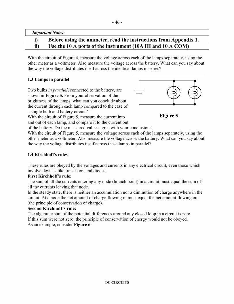
With the circuit of Figure 4, measure the voltage across each of the lamps separately, using the other meter as a voltmeter. Also measure the voltage across the battery. What can you say about the way the voltage distributes itself across the identical lamps in series? 1.3 Lamps in parallel Two bulbs in parallel, connected to the battery, are shown in Figure 5. From your observation of the brightness of the lamps, what can you conclude about the current through each lamp compared to the case of a single bulb and battery circuit? With the circuit of Figure 5, measure the current into and out of each lamp, and compare it to the current out of the battery. Do the measured values agree with your conclusion? With the circuit of Figure 5, measure the voltage across each of the lamps separately, using the other meter as a voltmeter. Also measure the voltage across the battery. What can you say about the way the voltage distributes itself across these lamps in parallel? 1.4 Kirchhoff=s rules These rules are obeyed by the voltages and currents in any electrical circuit, even those which involve devices like transistors and diodes. First Kirchhoff’s rule: The sum of all the currents entering any node (branch point) in a circuit must equal the sum of all the currents leaving that node. In the steady state, there is neither an accumulation nor a diminution of charge anywhere in the circuit. At a node the net amount of charge flowing in must equal the net amount flowing out (the principle of conservation of charge). Second Kirchhoff’s rule: The algebraic sum of the potential differences around any closed loop in a circuit is zero. If this sum were not zero, the principle of conservation of energy would not be obeyed. As an example, consider Figure 6.

- 47 -
DC CIRCUITS
Looking at the branch points B or E, we see that rule 1 implies:
I + I = I 321 (1) Looking at the loop ABEF we see that rule 2 implies: 0 = V + V + V batteryBEAB (2) Measure the currents I1, I2, and I3 by inserting the ammeter in branches AB, BE, and CD. Check the validity of Kirchhoff’s first rule (1). Measure the voltages across each of the lamps and across the battery (from F to A). Check the validity of Kirchhoff’s second rule (2). Part 2 Resistance - Ohm=s Law For many materials connected into electric circuits, the current (I) is simply proportional to the voltage difference (V) across that material. This proportionality is called Ohm’s Law:
RV = I (3)
The constant R is called the conductor=s resistance, measured in Ohms (Ω) in the SI system of units (1Ω = 1 Volt/1 Ampere). A resistor is simply a small piece of conductor which obeys Ohm’s law and which has been designed to have a specific value for its resistance. The purpose of this part of the experiment is to check if Ohm’s law holds for ordinary resistors, by measuring the voltage across the resistor and the current through it. 2.1 Ohm’s Law for a Resistor The circuit consists of an unknown resistance (0.2 kΩ - 2 kΩ) from the resistor box, connected to the power supply, as shown in Figure 7a. In order to measure the current through this resistor, an ammeter has to be placed in the circuit, as shown in Figure 7b.

- 48 -
DC CIRCUITS
Note: Use the mA ports of the instrument Observation: The introduction of the ammeter changes the current through the resistor, since every measuring meter has some resistance of its own. What should be the resistance of an ammeter so that this change is as small as possible? Note: If you are not sure how to connect the meters, read Appendix 1 - The use of voltmeters and ammeters. We need to measure the voltage across the resistor. This can be done by including a voltmeter in the circuit, as shown in either Figure 7c or 7d. Note that, in both circuits, the voltmeter will allow some current to pass through it, thus changing the current that flows through the resistor. What should be the resistance of a voltmeter so that this change is as small as possible? Using either circuit, take several readings of V and I and plot your data. Notes: The (random) reading errors on the multimeters follow the usual rules for digital instruments (about equal to half of the last digit) as long as all your readings remain on one scale. However for some multimeters, if you change scales during an experiment (as you almost certainly will) you may find that this error is an underestimate. In such cases the calibration error provided by the manufacturer should probably be used. Ssee specs on Faraday: the first number, quoted as a % is the calibration error, the second is the random error. Is Ohm’s law verified? Compare the slope of your line with the resistor=s nominal resistance (see Section 2.3 below). Which of the circuits (7c or 7d) is the best if the value of the resistor to be measured is very large (> 1 MΩ)?

- 49 -
DC CIRCUITS
2.2 Ohm’s Law for a Light Bulb Does the filament of a light bulb obey Ohm’s law? Measure a few values of V and I and again plot your data to test your hypothesis. Note: Use the red light bulb from the resistor box. Include measurements in which the light bulb is glowing. 2.3 Direct Measurement of the Resistance You can also use the lab multimeters to measure resistance directly, without taking separate V and I measurements. Use the resistance function to measure the equivalent resistance of a series and a parallel combination of two resistors. Finally, if time permits, quickly measure and record the resistance of a few conductors around the lab such as your skin, a laboratory hookup wire, a drop of water, etc. Note: To measure the potential difference V - V BA between two points A and B, connect the red
terminal of the voltmeter to A and the black terminal to B.
Don=t forget to turn off the multimeters and please return the wires to their proper location ! Appendix 1 - The use of voltmeters and ammeters
Ammeters: An ammeter measures the total current flowing in a wire. It has to be placed in series with that wire, i.e. the circuit connection to the wire must be cut and the ammeter placed in that cut. An ammeter must have two terminals, one for the current in and the other for the current out. A one-wire ammeter is an illogical entity. An ammeter is designed to pass all the current in the wire into which it is inserted without providing barriers to the flow of that current. Thus an ammeter should never be placed across the terminals of the battery, for such a connection would let the maximum current available from the battery to flow through the ammeter. So please do not connect the ammeter ACROSS a voltage source. Only connect it in series with the wire where you want to measure the current. Voltmeters: A voltmeter, as it measures the potential difference between two different wires, has to be connected in parallel with (across) those two wires. Unlike the ammeter, the circuit connection to the wires must be attached without breaking into the circuit. Note that a voltmeter must have two terminals as it is measuring a potential difference. A one-wire voltmeter is an illogical entity. Note that there is not the danger of passing excessive current through the voltage terminals as there was for the current terminals. Note: Read the Operating Instructions of these instruments from the section Commonly Used Instruments in the First Year Laboratory Manual.

- 50 -
DC CIRCUITS
Preparatory Questions Note: We hope that the following questions will guide you in your preparation for the experiment you are about to
perform. They are not meant to be particularly testing, nor do they contain any Atricks@. Once you have answered them, you should be in a good position to embark on the experiment.
1. You are given a flashlight battery, one piece of flexible wire, and a flashlight bulb. Sketch two different circuits that you could use to light the bulb. 2. Which is a more accurate way of determining a resistor=s resistance? a) Measuring it with a multimeter used as an ohmmeter or b) reading its color code. 3. A battery is a source of constant voltage. In the following two circuits it is indicated by B.
The direction of the current is indicated in both figures. The resistances have the values R1 = 500 Ω and R2 = 1,000 Ω. Which of the following statements is true? a) The current passing through R1 is half of the current passing through R2. b) The current passing through R1 is equal to the current passing through. R2. c) The current passing through R1 is twice the current passing through R2. Answer these questions for the circuits in the figures shown above. 4. In the circuit opposite, describe how you would measure the current flowing through the resistor.
This guide sheet was written by Ruxandra M. Serbanescu and Joe Vise in 2000 and revised by RMS in 2004.
Previous versions were written by Milton From and Tony Key.

THERMISTORS AND DIODES
- 51 -
THERMISTORS AND DIODES LYou may find the complete guide sheet at http://faraday.physics.utoronto.ca/IYearLab/dc2.pdf
The purpose of this experiment is to study the relationship between voltage and current in three non-linear circuit elements: a thermistor, a silicon diode, and an incandescent lamp. The apparatus consists of two multimeters, a switch, a power supply, a Thermos flask, and a thermometer for studying the thermistor at different temperatures. The resistance of the thermistor, as a function of temperature is expected to obey the relation
R = Roexp(To/T) (1) where T is the absolute temperature and Ro and To are constants (parameters) of the device.With the silicon diode, voltage vs. current curves should be obtained both in the forward (easy conduction) and reverse (almost impossible conduction) directions. Theoretically, one would expect the relation
I = Ioexp(V/Vo) (2) to hold approximately in the forward direction, where Io and Vo are parameters of the device. Another non-linear circuit element is the tungsten filament in a glowing incadescent lamp. Since the filament is made of the metal tungsten, Ohm’s law should still hold. The resistance of the filament is always given by R = V/I. However, as the lamp begins to glow, the resistance of the metal increases, unlike that of the thermistor. It is found both experimentally and theoretically that, above a certain temperature, the resistance R of a pure metal is, to within a few percent, directly proportional to the absolute temperature, R = k’T , with k’ a constant. This is sometimes written as R = RoT/ To where R is the resistance at temperature T and Ro is the resistance at some arbitrary temperature To. You will investigate the voltage-current data for the three non-linear circuit elements and check the validity of Equations 1 and 2. For the incandescent lamp, a numerical value for the constant n from the Stefan-Boltzman law should be calculated. D. Halliday, R. Resnick, and J. Walker. Fundamentals of Physics, 6th edition. Wiley, 2003.

THE ELECTROCARDIOGRAM
- 52 -
THE ELECTROCARDIOGRAM
You may find the complete guide sheet at
http://faraday.physics.utoronto.ca/IYearLab/EKG.pdf
The electrocardiogram (ECG or EKG) is a common diagnostic tool used to monitor heart activity. In this experiment you will study the Physics of the EKG. There are two investigations that you will do in this experiment: 1. Finding the potential difference between two points A and B due to an electric dipole. 2. Measuring the dipole moment of your heart as it contracts and relaxes and correlating
that measurement with the physiology of the contraction discussed above. Prerequisites to this experiment are • an understanding of the electric potential at about the level of OAC high school
Physics, • DC Circuits, and • any experiment that uses an oscilloscope. The experiment will count as two weights. The guide sheet contains more background material than is typical, particularly on the biophysics of muscles and the physiology of the heart.

DIGITAL ELECTRONICS
- 53 -
DIGITAL ELECTRONICS
LYou may find the complete guide sheet at http://faraday.physics.utoronto.ca/IYearLab/digital.pdf
This experiment is a basic introduction to digital logic. You should attempt it only if you either have some prior facility with circuit wiring or you have completed one of the electrical experiments, for example, DC Circuits or Charge and Discharge of a Capacitor. The experiment investigates how transistor devices are used to make various logic circuits. It is in two parts, each part having a value of two weights. Part I studies the Basic Unit, AND gates, OR gates, and binary adders. Part II studies bistable circuits, flip-flops, memories, and timing devices. All of these components are available at the Resource Centre. The experiments do not investigate WHY a transistor behaves as it does, but concentrates on WHAT it does. As the circuits studied become progressively more complex, the experiments tend more towards logic than electronics. L.R. Fortney. Principles of Electronics, chapter 9. F.J. Holler, J.P. Avery, S.R. Crouch, and C.G. Enke. Experiments in Electronics, Instrumentation and Microcomputers. Don Lancaster. TTL Cookbook. Circuit Wiring Techniques of this Lab Manual. Commonly Used Instruments: The Multimeter and Commonly Used Instruments: The Oscilloscope of this Lab Manual.

CHARGE AND DISCHARGE OF A CAPACITOR
- 54 -
CHARGE AND DISCHARGE OF A CAPACITOR
LYou may find the complete guide sheet at http://faraday.physics.utoronto.ca/IYearLab/capacitor.pdf
There are numerous natural processes in which the rate of change of a quantity is proportional to that quantity. A radioactive example is the case in which the rate of loss of the number of nuclei is proportional to the number of nuclei present. The number of nuclei decreases exponentially. An electrical example of exponential decay is that of the discharge of a capacitor through a resistor. A capacitor stores charge, and the voltage V across the capacitor is proportional to the charge q stored, given by the relationship V = q/C, where C is called the capacitance. A resistor dissipates electrical energy and the voltage V across it is proportional to the current, which is just the rate of charge flow through it, given
by dtdq R = V ⋅ , where R is called the resistance.
When a charged capacitor is connected to a resistor, the charge flows out of the capacitor and the rate of loss of charge on the capacitor as the charge flows through the resistor is proportional to the voltage, and thus to the total charge present.
In terms of voltage, this can be expressed as: eV = V RCt /0
−
$ The data you take should test whether the voltage across the discharging capacitor VC shows
exponential behaviour. $ Use the oscilloscope to determine time and voltage values for particular values of R and C. Record
VC as a function of t. D. Halliday, R. Resnick, and J. Walker. Fundamentals of Physics, 6th edition. Wiley, 2003.

FARADAY’S LAW AND THE AC GENERATOR
- 55 -
FARADAY’S LAW AND THE AC GENERATOR
LYou may find the complete guide sheet at http://faraday.physics.utoronto.ca/IYearLab/faraday.pdf
A large fraction of the electrical power used by the world today is obtained by converting the rotational energy of a turbine into electrical energy. This is usually done by having the turbine turn a coil of wire inside a region where there is a strong magnetic field. The production of an electric current in this manner is explained by Faraday=s Law, one of the most important laws of Electricity and Magnetism. In this experiment you will examine several quantitative aspects of Faraday’s Law. The apparatus consists of a rectangular coil of wire that can be rotated at a steady angular frequency in the uniform magnetic field B generated by two stationary coils. Both the rotating coil=s angular frequency and the strength of the magnetic field can be varied. The electro-motive force (emf) generated in the rotating coil can be measured and compared with the predictions of Faraday=s Law. According to Faraday and Henry, the emf induced in a coil depends on - the rate of change of B through the coil and - the rate of change of the perpendicular area of the coil penetrated by the magnetic field lines. The circuit used in this experiment includes two coils in Helmholtz configuration that generate an uniform B, DC power supply, variable resistor, and digital ammeter. An analogue AC voltmeter is connected across the rotating coil. Sequences of measurements are necessary to investigate the variation of the peak emf as a function of the rotation frequency and as a function of the current in the Helmholtz coils. From these measurements you will determine a value for the constant µ0 and estimate the magnitude of the external magnetic field in the Physics building. D. Halliday, R. Resnick, and J. Walker. Fundamentals of Physics, 6th edition. Wiley, 2003. R.A. Serway. Physics for Scientists and Engineers, 4th edition, vol. 2. Saunders College Publ., 1996.