Embed Size (px)
Citation preview

Preprint submitted to Carbon May 20, 2019
THE MECHANICAL AND ELECTRICAL PROPERTIES OF
DIRECT-SPUN CARBON NANOTUBE MAT-EPOXY
COMPOSITES
Wei Tan, Joe C. Stallard, Fiona R. Smail, Adam M. Boies, Norman A. Fleck*
Engineering Department, University of Cambridge, Trumpington Street, Cambridge, CB2 1PZ, UK.
*Corresponding author. Tel: +44 (0)1223 748240. Email: [email protected] (N.A. Fleck)
Abstract:
Composites of direct-spun carbon nanotube (CNT) mats and epoxy are manufactured and
tested in order to determine their mechanical and electrical properties. The mats are spun
directly from a floating catalyst, chemical vapour deposition reactor. The volume fraction of
epoxy is varied widely by suitable dilution of the epoxy resin with acetone. Subsequent
evaporation of the acetone, followed by a cure cycle, leads to composites of varying volume
fraction of CNT, epoxy and air. The modulus, strength, electrical conductivity and
piezoresistivity of the composites are measured. The CNT mats and their composites exhibit
an elastic-plastic stress-strain response under uniaxial tensile loading, and the degree of
anisotropy is assessed by testing specimens in 0°, 45° and 90° directions with respect to
the draw direction of mat manufacture. The electrical conductivity scales linearly with CNT
volume fraction, irrespective of epoxy volume fraction. In contrast, the modulus and strength
depend upon both CNT and epoxy volume fractions in a non-linear manner. The
macroscopic moduli of the CNT mat-epoxy composites are far below the Voigt bound based
on the modulus of CNT walls and epoxy. A micromechanical model is proposed to relate the
macroscopic modulus and yield strength of a CNT mat-epoxy composite to the
microstructure.

2
1. Introduction
1.1 Properties of CNT-polymer composites
The impressive mechanical, electrical and thermal properties of individual carbon nanotubes
(CNTs) have attracted considerable interest from the research community [1,2]. The wall of
a CNT has an elastic modulus of about 1 TPa, a tensile strength of 100 GPa [3], a thermal
conductivity of 3500 W/mK [4], and an electrical conductivity of 2 × 10⁷ S/m [5]. Several
thousand tonnes of CNTs are now produced each year in powder form [1], yet the annual
production of CNT mats and yarns is only a small proportion of global output. Although the
high production cost precludes their use in many engineering applications, it is anticipated
that CNT mats will be produced in industrial volumes, suitable for processing into high-
performance CNT-based composites [6].
CNT-polymer composites exist in five categories, as labelled (a) to (e) in Figure 1, and are
summarised as follows:
Class (a): Short CNTs in powder form can be dispersed in molten polymers or polymer-
solvent solutions, often with the aid of surfactants [7]. These CNT-polymer solutions can
then be cast into a mould to form CNT-polymer composites [8–10]; the content of CNTs in
such composites is typically less than 4% by weight.
Classes (b) and (c): Alternatively, CNT-solvent solutions can be injected into a bath of
coagulating polymer solution to form unidirectional CNT-polymer fibres [11–13], termed
class (b), or filtered to create planar isotropic ‘buckypaper’ mats, which are subsequently
processed into planar composites via the infiltration of polymer solutions [14–17], class (c).

3
Class (d): Vertically aligned CNT forests are grown from substrates. They can then be
infiltrated with polymers and cured in the vertically aligned form [18], or processed into a mat
in the dry state by drawing or by flattening via the so-called ‘domino pushing’ process [19–
21]. In a variant of this class, twisting is imposed during drawing or after flattening to produce
a unidirectional fibre. Mats or fibres manufactured from CNT forests are subsequently
processed into CNT-polymer composites via the infiltration and cure of polymer solutions
[20–29].
Class (e): CNT mats and fibres are collected continuously by drawing CNT aerogels from
a floating catalyst chemical vapour deposition reactor. These so-called “direct-spun”
materials can be infiltrated with polymer solutions to create CNT-polymer composites [30–
35]. It is this last set of materials which form the focus of the current study. The performance
of such composites in the drawn direction may be enhanced by stretching [30,31] or by the
application of pressure during cure [36]: these processes can raise the CNT volume fraction
and align the CNTs with the loading direction.
The reported moduli and strength of these classes of CNT-based composites [8-17,20-35]
are assembled in Figure 2(a). For comparison, the strength and modulus of individual CNT
walls [3,37] are included. Note that the moduli and strength of CNT-based composites span
several orders of magnitude for composite densities in the narrow range of 800 kg/m3 to
1200 kg/m3. Also, the moduli and strength of CNT composites are much below those of CNT
walls [38–43], and are dependent on the orientation and waviness of the CNT reinforcement
[44], and on the CNT volume fraction [18]. The chart of electrical and thermal conductivity
Figure 2(b), assembled from the data of [4,17,27,45–54], reveals that the electrical and
thermal conductivity of CNT composites are also orders of magnitude below those of
individual CNT walls, and these properties vary not only within a class of material but also
between composite classes.

4
In broad terms, CNT-epoxy composites consist of a combination of three phases: CNTs,
epoxy and air. A composition diagram is given in Figure 2(c) to indicate the relative volume
fraction of CNT bundles 𝑓𝐵, epoxy 𝑓𝑒 and of air 𝑓𝑎. The figure includes CNT foams [55], CNT
fibres [56,57], and CNT mats [57–60] for which 𝑓𝑒 = 0. CNT foams possess a CNT volume
fraction 𝑓𝐵 < 0.10, whilst dry CNT fibres and mats possess 0.10 < 𝑓𝐵 < 0.82. Most quasi-
isotropic CNT-epoxy composites [33,35,53,61] have a volume fraction 𝑓𝐵 < 0.40, whereas,
for aligned CNT-epoxy composites, 𝑓𝐵 is typically in the range 0.60 < 𝑓𝐵 < 0.70 [30,31,36].
The in-plane modulus of carbon nanotube composites 𝐸, as reported in [8-17,20-35] and as
measured in this study, are compared with those of long fibre carbon fibre composites in
Figure 2(d) by plotting 𝐸 versus reinforcement volume fraction 𝑓𝑅. For CNT bundles, we take
𝑓𝑅 = 𝑓𝐵. The normalisation of 𝐸 for CNT-based composites and carbon fibre composites is
chosen as follows. For the CNT-based composites, the modulus 𝐸 is normalised by that of
an individual CNT bundle, 𝐸𝑅 = 680 GPa [57]. Recall that the axial modulus of a
unidirectional (UD) carbon fibre-epoxy lamina can be two orders of magnitude greater than
the transverse modulus due to the extreme anisotropy of the fibres. Here, we shall define
the term ‘composite modulus’, 𝐸, as the largest principal value of the modulus tensor. It is
this modulus 𝐸, normalised by the modulus of the carbon fibres as used in each separate
study [62–67], that is plotted Figure 2(d) as a function of reinforcement volume fraction 𝑓𝑅.
The data used for these composites are given in full in Table S1 of the supplementary
information.
Voigt and Reuss bounds are included in Figure 2(d). The knockdown in macroscopic
modulus from the Voigt bound is sensitive to composite microstructure. The modulus of
unidirectional (UD) CFRP composites is close to the Voigt bound, whilst the modulus of a
quasi-isotropic planar CFRP laminate lies below it by a factor of about ×3 due to the
presence of reinforcement fibres orientated away from the principal direction. Note that the

5
modulus of the unidirectional forest-drawn CNT-polymer composites are below the Voigt
bound by more than a factor of 2, whilst those measured from composites of direct-spun
CNT mats in this study lie on average more than a factor of 3 below those drawn from forests.
The effect of CNT waviness, aspect ratio, and the uniformity of reinforcement volume
fraction have been explored theoretically for CNT composites using classical bounds [68]
and micromechanical models [44]: the presence of waviness, in particular, knocks down the
macroscopic modulus by more than an order of magnitude [44].
1.2 Scope of Study
The purpose of the present study is to determine experimentally the effect of epoxy
infiltration upon the tensile stress-strain response and electrical conductivity of direct-spun
CNT mat-epoxy composites over a broad compositional range, and to understand the
relationship between microstructure and properties through experiment and
micromechanical modelling. Composites of CNT volume fraction between 0.11 and 0.35,
and epoxy volume fraction between 0.01 and 0.79, were produced by the solvent-assisted
infiltration of a direct-spun CNT mat with epoxy. The composition was controlled via the
initial concentration of epoxy in acetone, and by applying varying consolidation pressures.
The in-plane uniaxial tensile response and electrical properties were measured by tensile
tests and a four-point electrical probe method, respectively. Scanning and transmission
electron microscopy were used to characterise the epoxy distribution at the microstructural
level. A micromechanical model was then developed to relate the macroscopic modulus and
strength to the microstructure of the direct-spun CNT mat and CNT-epoxy composites.

6
2. Manufacture and composition of materials
2.1 Manufacture of CNT mat
Direct-spun CNT mat was produced by the floating-catalyst chemical vapour deposition
(FCCVD) process1, as initially described by Li et al [69]; the process is discussed in more
detail elsewhere [70]. In brief, a CNT aerogel sock is drawn continuously from a FCCVD
reactor and wound onto a mandrel, thereby forming a multi-layer carbon nanotube mat [57].
The hierarchical microstructure of the direct-spun CNT mat is sketched in Figure 3. The mat
is of width 0.9 m and thickness 70 μm, and is comprised of flattened CNT aerogel socks.
Each flattened sock is of width 80 mm and thickness about 170 nm, and is comprised of a
network of branched CNT bundles, forming an interconnected network. Each bundle
consists of between 10 and 40 closely packed CNTs. Macroscopically, direct-spun mats
possess in-plane anisotropy in their mechanical and electrical properties, and the anisotropy
is sensitive to the ratio of the velocity of the drawn aerogel to that of the gas flow within the
reactor [71]. The principal material orientation is along the draw direction of the CNT sock in
the reactor.
2.2 Manufacture of CNT-epoxy composites
The production method for fabricating the CNT-epoxy composites is sketched in Figure 4.
Samples were cut from a single ply of direct-spun CNT mat of width 10 mm, length 80 mm,
and nominal thickness 70 μm. They were then infiltrated by a solution of epoxy in acetone,
followed by evaporation of the acetone under vacuum, and by curing in a hot press. The
epoxy resin was bisphenol-A IN2 infusion resin and a hexane hardener2. The epoxy resin
1 Provided by Tortech Nano Fibers Ltd, Hanassi Herzog St., Koren Industrial park, Ma’alot Tarshiha, 24952 Israel. 2 IN2 epoxy infusion resin and a vacuum bagging system were obtained from Easy Composites Ltd, Park Hall Business Village, Longton, Stoke on Trent, Staffordshire, ST3 5XA, UK

7
and hardener were mixed in the proportion 10:3 by mass, and were then diluted with acetone.
The mass concentration of resin and hardener in this solution, as denoted by 𝜙, varied from
0.001 to 1. By infiltrating the CNT mat with epoxy-acetone solutions of selected values of 𝜙,
the volume fraction of epoxy in the cured composite could be suitably controlled. After
immersion of the CNT mat samples in the epoxy-acetone solution for 60 s, manufacture
proceeded along one of two routes, see Figure 4. In the first route, the infiltrated CNT mat
samples were placed between an inner layer of PTFE release film and an outer breather
layer, and a vacuum bagging system2 was used to apply a consolidation pressure of 𝑃 = 0.1
MPa (one atmosphere), at a temperature of 40 °C for one hour. Excess resin was absorbed
by the breather layer material on each side of the CNT-epoxy composites during
consolidation. Samples were then cured in a hot-press at 120 °C for 3 hours, with a constant
pressure of 0.6 MPa in the through-thickness direction. An alternative production route was
used to manufacture CNT composites of higher CNT volume fraction: infiltrated CNT mat
samples were placed between PTFE films, and were subjected to a through-thickness
pressure of 𝑃 = 10 MPa between the loading platens of a screw-driven test machine. Since
the samples were compressed between the PTFE films, squeeze-out of excess epoxy was
prevented. After the consolidation pressure had been applied for three hours, allowing the
epoxy to cure partially within the densified CNT mat, the samples were placed within the
same vacuum bagging system as that described above (pressure of 0.1 MPa and a
temperature of 40 °C for one hour) to remove residual acetone or volatile compounds. The
samples were then cured in a hot press at 120 °C for three hours, under the same conditions
as for the first route.
Dogbone specimens of pure, void free epoxy were also prepared for uniaxial testing. Epoxy
solutions were cast into a mould, and degassed in a vacuum chamber for 1 hour, before
curing at 120 °C for 3 hours. To determine the effect of acetone dilution upon the mechanical
properties of the epoxy, additional dogbone samples were cast from a solution of acetone

8
and epoxy, with 𝜙 = 0.5. The acetone was then removed by degassing under vacuum in the
same manner, and the sample was cured as above.
2.3 Composition and physical properties of CNT mat and composites
The volume fraction of CNT bundles 𝑓𝐵 and volume fraction of epoxy 𝑓𝑒 are related to the
corresponding weight fractions of CNT bundles and epoxy 𝑤𝐵 and 𝑤𝑒 respectively, as
follows. Write 𝜌𝐵 as the CNT bundle density and 𝜌𝑒 as the measured epoxy density. Then,
upon writing 𝜌 as the measured composite density, we have
𝑓𝐵 = 𝑤𝐵𝜌
𝜌𝐵, 𝑓𝑒 = 𝑤𝑒
𝜌
𝜌𝑒. (1)
The weight fraction of CNT bundles in the composite 𝑤𝐵 is the ratio of the mass of CNT
bundles to the mass of the composite, and the weight fraction of epoxy follows directly as
𝑤𝑒 = 1 − 𝑤𝐵. Both the mass of the CNT mat before infiltration and the mass of the cured
CNT-epoxy composite were measured with a mass balance. The width and length of
samples was measured with a Vernier scale, and the thickness was measured by
micrometer, and averaged over ten readings along the sample length. The density of the
composite 𝜌 was determined via its mass and volume. The dependence of thickness 𝑡 upon
composite density 𝜌 is recorded in Figure S1 of the supplementary information. For samples
of direct-spun CNT mat, the thickness was confirmed by X-ray tomography, as this method
avoids compression of the sample during measurement.
The CNT bundle density 𝜌𝐵 was determined by helium pycnometry3 [57], as follows. A CNT
mat sample was placed in a vacuum chamber of known volume, and the chamber was then
filled with helium gas. After measuring the pressure within the chamber, a valve was opened
to link it to a second vacuum chamber of known volume. The final pressure was recorded
3 Quantachrome UK Ltd, Units 6 7 Pale Lane Farm, Pale Lane, Hook, RG27 8DH, UK

9
after equilibrium had been attained. The ideal gas law was used to calculate the sample
volume from the measured gas pressures and the known chamber volumes. The bundle
density follows immediately from the sample mass divided by the sample volume, giving
𝜌𝐵 = 1560 kg/m3. The density of the epoxy, as calculated from the measured epoxy dogbone
sample dimensions and mass, was 𝜌𝑒 = 1120 kg/m3. Finally, the porosity of the composites,
referred to here as the volume fraction of air 𝑓𝑎 , was determined by subtracting the
calculated volume fraction of CNT bundles and of epoxy from unity.
The densities of the mat and of the CNT-epoxy composites, and the volume fractions of CNT
bundles, epoxy and air are recorded in Table 1 as functions of the weight fraction of epoxy
in the infiltration solution 𝜙 and of the through-thickness pressure 𝑃 applied after infiltration.
The as-received CNT mat specimens (absent infiltration) are labelled (1). CNT mat-epoxy
composites manufactured at 𝑃 = 0.1 MPa are labelled (2) to (9) in order of increasing 𝜙,
such that (9) corresponds to a composite made from undiluted epoxy (𝜙 = 1) and CNT mat.
Cured epoxy dogbone samples with initial concentration of epoxy in acetone 𝜙 = 0.5 and 𝜙
= 1 are labelled (10) and (11), respectively. Two composites (5h) and (6h) were
manufactured with the high pressure 𝑃 = 10 MPa, from an epoxy-acetone mix equal to that
of (5) and (6), respectively. Additionally, a sample of direct-spun mat (1h) was infiltrated with
acetone and subjected to the same through-thickness pressure of 𝑃 = 10 MPa.
The dependence of as-cured density 𝜌 upon the initial epoxy concentration 𝜙 of the epoxy-
acetone solution is plotted in Figure 5(a) for 𝑃 = 0.1 MPa and 𝑃 = 10 MPa. The density 𝜌
relates to the densities and volume fractions of CNT bundles and epoxy according to 𝜌 =
𝑓𝐵𝜌𝐵 + 𝑓𝑒𝜌𝑒. We note that 𝜌 increases monotonically with increasing 𝜙, for each selected
value of 𝑃. Thus, it is convenient to report the composition and properties of each composite
against 𝜌 rather than the process variable 𝜙. We also note from Figure 5(a) that 𝜌 increases
with increasing 𝑃 at any fixed value of 𝜙. The volume fractions of CNT bundles, epoxy and

10
air are plotted against the macroscopic composite density in Figure 5(b) for composites
fabricated at 𝑃 = 0.1 MPa, that is by consolidation under vacuum before curing, and in Figure
5(c) for samples that were subjected to 𝑃 = 10 MPa pressure after infiltration. Samples
fabricated at 𝑃 = 0.1 MPa exhibit a maximum CNT volume fraction of 𝑓𝐵 = 0.25 at 𝜌 = 771
kg/m3, see sample (6) in Figure 5(b). In contrast, 𝑓𝐵 rises monotonically with increasing 𝜌 for
the choice 𝑃 = 10 MPa. The non-linear dependence of 𝑓𝐵 upon (𝜌, 𝑃) arises from the
transient consolidation response of the bundles in the presence of an evaporating solvent,
acetone, and a curing matrix, epoxy.
3. Measured properties of CNT mat and CNT-epoxy composites
3.1 Morphology of CNT Mats and CNT-epoxy composites
The CNT mat and CNT composite microstructures were imaged by scanning electron
microscope (SEM), using a voltage of 5 kV and a spot size of 3 μm. A field emission
transmission electron microscope (FEGTEM), fitted with energy-dispersive X-ray
spectroscopy (EDX) was used to characterise the bundle microstructure of the CNT mat and
CNT-epoxy composites. Samples of the as-received CNT mat were prepared for TEM
analysis by depositing a small quantity of aerogel layers from the delaminated mat onto a
copper mesh, with the aid of acetone solvent. Composites were also prepared for TEM
analysis by using a modified epoxy resin containing uniformly distributed silicon side-groups4,
so that the distribution of epoxy in the composite could be identified by elemental EDX
mapping of the silicon group distribution. A focused ion beam (FIB)5 was used to mill
samples of direct-spun CNT mat and CNT-epoxy composites in their through-thickness
direction in order to reveal the bundle microstructure in the cross-sectional view. A beam
4 SILIKOFTAL® ED, Evonik, Tego House, Chippenham Dr, Kingston, Milton Keynes, MK10 0AF, UK 5 SEM/FIB Workstation, Helios Nanolab DualBeam 600. Thermo Fisher Scientific, 168 Third Avenue, Waltham, MA, USA 02451.

11
current of 2.8 nA was used for refined milling prior to imaging. For TEM analysis, samples
were also prepared by FIB cutting, using a lift-out process as described elsewhere [72]. This
method produced samples of suitable thickness between 100 nm and 150 nm.
Plan views of CNT mat microstructure and CNT composite microstructure with selected
values of epoxy content are presented in Figure 6(a-c), and images of their cross-section in
the through-thickness direction are shown in Figure 6(d-f). The CNT mat microstructure, as
displayed in Figure 6(a) and 6(d), consists of a random network of CNT bundles, with
branching of CNTs from bundle to bundle. The bundle cross sections are typically circular.
In composites of low epoxy content, the epoxy uniformly coats the CNT bundle network, see
Figure 6(b) and 6(e); some of the CNT bundles appear flattened in cross-sectional view
compared to the dry state. As the epoxy content increases, it progressively fills the air space
between CNT bundles until close to fully dense, see Figure 6(c) and 6(f). SEM and TEM
images of the CNT-epoxy composite cross-section reveal an almost uniform volume fraction
𝑓𝑒 of epoxy in the through-thickness direction.
A plan view image of a CNT bundle in the as-received direct-spun mat from TEM is shown
in Figure 6(g), revealing the crystalline, close-packed CNT bundle microstructure. A
complementary, transverse image of a CNT bundle cross section in the direct-spun
mat/silicone epoxy resin composite, produced from a cross-sectional cut of the composite
in the through-thickness direction, is given in Figure 6(h). The CNTs are predominantly multi-
walled, and the individual CNTs within a bundle remain close-packed after epoxy infiltration.
Elemental mapping of this bundle cross-sectional view is shown in Figure 6(i), revealing the
distribution of silicon-tagged epoxy within the microstructure. The elemental mapping shows
that the epoxy resin surrounds the bundle, and wets the bundle surface, but does not
penetrate the gap between neighbouring CNTs of each bundle.

12
3.2 Uniaxial tensile tests
Uniaxial tensile tests were performed on the CNT mat, CNT-epoxy composites, and the
epoxy matrix, using a screw-driven test machine6 at a strain rate of 𝜖̇ = 10-4 s-1. The ends of
the specimens were placed in wedge grips and were cushioned by paper end tabs, see
Figure 7(a). The axial nominal strain in the gauge section was measured by the axial
displacement of two dot stickers. The dots were of diameter 0.5 mm and of spacing 30 mm,
and were adhered to the sample prior to testing. The relative displacement of the dots was
tracked at a frequency of 1 Hz by a suitable camera system7. For the as-received direct-
spun CNT mat, the yield stress is inferred from the stress-strain response via a bilinear fit,
whilst for the CNT-epoxy composites, it is determined by finding the intersection of the
stress-strain curve with a line drawn parallel to the initial, linear curve but offset by 0.2% in
strain. The dimensions of the cast epoxy samples for uniaxial tensile testing are given in
Figure 7(b); the tensile strain was again measured with the optical extensometer as
described above.
The tensile uniaxial stress-strain response of CNT mat, CNT-epoxy composites and epoxy
are plotted in Figure 8(a)-(c). In order to determine the degree of in-plane anisotropy, tensile
tests were conducted on samples of dry mat (1) and composite (9), oriented at 0°, 45° and
90° to the principal material orientation, see Figure 8(a). Both materials exhibit moderate in-
plane anisotropy. The ductility of the composite is inferior to that of the as-received mat, but
the strength and stiffness are both enhanced. The uniaxial tensile responses of CNT mat-
epoxy composite samples oriented at 0° to the principal material direction, and consolidated
under atmospheric vacuum, are compared with those of the as-received CNT mat and cured
6 Instron Ltd, Coronation Road, High Wycombe, Buckinghamshire, HP12 3SY, UK. A load cell of maximum capacity 500 N was used for all tests. 7 GOM UK Ltd, 14 Siskin Parkway East, The Cobalt Centre, Coventry, CV3 4PE, UK.

13
epoxy dogbone samples in Figure 8(b). Note that the stress-strain responses of the
composites are much higher than those of the epoxy and direct-spun mat. The mechanical
behaviour of the epoxy dogbone samples is almost insensitive to the initial concentration of
epoxy in acetone, prior to evaporation of the acetone, see samples (10) and (11) in Figure
8(b). The stress-strain response of samples oriented at 0° to the principal material direction
and subjected to a 10 MPa pressure prior to cure are compared with those that have been
consolidated under vacuum in Figure 8(c). Consolidation with a 10 MPa through-thickness
pressure results in superior mechanical properties for both the direct-spun mat and
composites; these composites exhibit the highest strength of 410 MPa and stiffness of
almost 30 GPa in the present study.
The modulus, yield strength and ultimate strength of CNT mat-epoxy composites, direct-
spun mat, and epoxy are plotted against the measured sample density in Figure 8(d), (e)
and (f), respectively. The modulus and strength are dependent on the volume fraction of
both CNTs and epoxy in a non-linear manner. The greatest measured moduli and yield
strengths of CNT-epoxy composites lie approximately an order of magnitude above the
corresponding values for the unreinforced, as-received CNT mat, or the epoxy measured in
bulk form. Also, the high pressure cure cycle leads to an increase in modulus and strength
by a factor of about 2 for the same density.
3.3 In-plane electrical properties, unloading and piezoresistive behaviour
The in-plane electrical conductivity of the CNT mat and of the CNT-epoxy composites were
measured by a four-point probe method prior to mechanical tensile testing; the sample
dimensions and experimental setup are described in Figure 7(c). Contacts of adequately
low resistance for 4-point testing were made by laying the samples on copper contacts. The
presence of breather layer material on each side of the composites during cure meant that

14
excess resin was removed by the applied vacuum and reliable electrical contacts were
achieved. The only instance where the electrical contact did require improvement was for
composite (9); in this case, mild sanding of the surface was sufficient to ensure a satisfactory
electrical contact. To verify that the electrical current density was constant over the sample
cross-section, measurements of the potential drop along the gauge length were taken both
on the side of the sample on which the current probes were placed, and on the opposite
side. It was noted that current flow was uniform throughout the thickness.
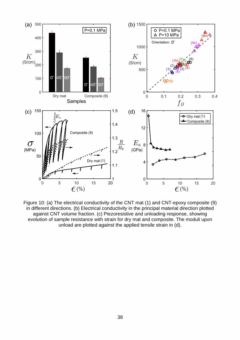
The in-plane electrical conductivity measured from samples of direct-spun CNT mat (1)
oriented at 0°, 45° and 90° to the principal material orientation, and of CNT-epoxy composite
(9), are given in the bar chart of Figure 10(a); the electrical conductivity of both the direct-
spun mat and composite exhibit similar levels of anisotropy. The electrical conductivity of
direct-spun CNT mats and composites measured along the principal material orientation is
plotted against the CNT volume fraction 𝑓𝐵 in Figure 10(b): the electrical conductivity 𝐾
scales linearly with CNT volume fraction 𝑓𝐵.
A limited number of tensile tests were also conducted with simultaneous measurement of
the electrical resistance within the central portion of the sample gauge length, to compare
the in-plane piezoresistive behaviour and post-yield mechanical response of the CNT mat
(1) and CNT-epoxy composite (9); the results are given in Figure 10(c). Current and voltage
probes were attached to the sample with electrically conductive silver paint, and the
resistance was measured at a frequency of 1 Hz. A constant current of 25 mA was supplied
to the sample throughout the test, and partial unloading was conducted at regular intervals.
The measured sample resistance 𝑅 is normalised in Figure 10(c) by its value 𝑅0 at the start
of the test. The unloading modulus of the samples 𝐸𝑢 as defined by the gradient of the
stress-strain response at the onset of unloading, are plotted in Figure 10(d) as a function of
axial strain. The unloading modulus of the CNT mat increases with increasing strain, and
this is due to the progressive alignment of CNT bundles with the loading direction. In contrast,

15
the unloading modulus of the composite decreases with increasing strain. This is suggestive
of microstructural damage, presumably in the form of cracking of the epoxy matrix [2].
4. A micromechanical model for modulus and yield strength
A micromechanical model is now developed, based on the characterisation of the underlying
material microstructure, to understand the origin of the stiffening and strengthening due to
the epoxy matrix within the CNT mat.
4.1 An idealisation of CNT mat-epoxy composite microstructure
The unreinforced CNT mat microstructure consists of an interlinked network of nanotube
bundles. The bundles are connected by the branching of CNTs from one bundle to the next.
This random, interconnected, dry bundle network has a nodal connectivity of between 3 and
4, and earlier in-situ experiments [57] reveal that it deforms in a foam-like manner,
predominantly due to bending and shearing of the CNT bundles, rather than by their axial
stretch. For an estimation of strength and stiffness, this microstructure motivates the use of
a periodic, planar hexagonal honeycomb network, represented by a repeating honeycomb
unit cell of interlinked CNT bundle struts and epoxy, as illustrated in Figure 9(a). This unit
cell was used before as an idealisation for dry CNT mat, and provided a useful estimate for
the dry CNT mat modulus and yield strength [57]. Microscopy of the composites reveals that
the outer surfaces of the CNT bundles are coated with epoxy, and that the epoxy does not
infiltrate the bundles, see Figure 6(h) and (i). An increase in volume fraction of epoxy leads
to progressive filling of the pores between the bundles. Here, we vary the volume fractions
of CNT bundles, epoxy and air in the unit cell according to their values recorded in
experiment, and assume that the epoxy extends from the CNT bundle struts into the centre
of the pores, with thickness equivalent to that of the bundles in the out-of-plane direction, as
shown in Figure 9(b). Finite element calculations were conducted to model the stress-strain
response of this honeycomb unit cell in plane stress, using the commercially available finite

16
element package ABAQUS Standard (version 6.14). The simulation set up and boundary
conditions are illustrated in Figure 9(c); the roller boundary conditions were defined such
that there are vanishing components of stress in the 𝑥2 direction, and to achieve symmetry
and deformation consistent with that of the periodic honeycomb network. A perfect-bond
between the CNT bundles and epoxy is assumed. The degree of anisotropy of response of
the unit cell is controlled by suitable choice of the initial value of the angle 𝜔, which is a
measure of the alignment of the CNT bundle microstructure with the principal material
direction. The thickness of the CNT bundle struts and epoxy layer are listed in Table S2 of
the supplementary information for the simulations, alongside illustrations of the simulated
unit cell over the compositional range of CNT-epoxy composites and direct-spun mat in
Figure S2.
4.2 Constitutive model for CNT bundles and matrix
Covalent bonding within the CNT walls endows them with high axial strength and stiffness.
In contrast, the bonds between adjacent CNT tubes are comparatively weak, and hence the
longitudinal shear modulus and shear strength of CNT bundles is much below their axial
modulus and strength in tension [3,73,74]. Here, we recognise that CNT bundles are
transversely isotropic with respect to their longitudinal axis, and treat the CNT bundle as an
anisotropic, homogeneous continuum. We define the constitutive relationships as follows.
Consider first the elastic response of CNT bundles. The elastic strain 𝜀𝑖𝑗𝑒 is related to the
stress 𝜎𝑖𝑗 by:

17
{
𝜀11𝑒
𝜀22𝑒
𝜀33𝑒
𝛾23𝑒
𝛾13𝑒
𝛾12𝑒 }
=
[ 1𝐸11𝐵⁄ −
𝜈21𝐸22𝐵⁄ −
𝜈31𝐸33𝐵⁄ 0 0 0
−𝜈12
𝐸11𝐵⁄ 1
𝐸22𝐵⁄ −
𝜈32𝐸33𝐵⁄ 0 0 0
−𝜈13
𝐸11𝐵⁄ −
𝜈23𝐸22𝐵⁄ 1
𝐸33𝐵⁄ 0 0 0
0 0 0 1𝐺23𝐵⁄ 0 0
0 0 0 0 1𝐺13𝐵⁄ 0
0 0 0 0 0 1𝐺12𝐵⁄ ]
{
𝜎11𝜎22𝜎33𝜏23 𝜏13𝜏12}
(2)
We proceed to obtain estimates for the elastic constants in (2). Further details of our
methods and constants used in calculation are provided in Section 2 of the supplementary
information. The modulus of CNT walls measured in axial tension, and based upon an
assumed interlayer spacing of 0.335 nm, is taken to be 1 TPa [3,75,76]. We estimate the
bundle axial modulus by assuming all CNT walls within the bundle cross-section are
subjected to a uniform tensile strain. The longitudinal CNT bundle modulus 𝐸11𝐵 is related to
the wall modulus 𝐸𝑤 and wall density 𝜌𝑤 by 𝐸11𝐵 = 𝐸𝑤(𝜌𝐵 𝜌𝑤⁄ ) [77]. Substitution of the
measured values of measured bundle density 𝜌𝐵 and wall density 𝜌𝑤 = 2300 kg/m3 implies
that 𝐸11𝐵 = 680 GPa. Suggested values within the literature [78,79] for the transverse
modulus 𝐸22𝐵 = 𝐸33
𝐵 for bundles of single-walled CNTs range from 40 GPa to 78 GPa. Here,
we assume that 𝐸22𝐵 = 𝐸33
𝐵 = 50 GPa, and take the Poisson ratio to be 𝜈12 = 𝜈13 = 0.3. The
low values of bundle shear moduli 𝐺12𝐵 , 𝐺13
𝐵 and 𝐺23𝐵 all result from the weak interfacial
bonding between CNTs, and we assume that they are all equal. By calibration of the
predicted macroscopic stiffness of the CNT honeycomb with the measured modulus of the
dry unreinforced CNT mat upon unloading, we already deduced in a previous study [57] that
𝐺12𝐵 = 9.5 GPa, and this value is again used herein.
Now consider the strength and post-yield behaviour of a CNT bundle. Hill’s anisotropic yield
criterion [80] is used here to represent the post-yield behaviour of the CNT bundles. The
total strain rate 𝜀�̇�𝑗 is the sum of the elastic strain rate 𝜀𝑖𝑗�̇� and plastic strain rate 𝜀�̇�𝑗
𝑝,

18
𝜀�̇�𝑗 = 𝜀�̇�𝑗𝑒 + 𝜀�̇�𝑗
𝑝. (3)
The plastic strain rate is defined by the associated flow rule,
𝜀�̇�𝑗𝑝= �̇�
𝜕Φ
𝜕𝜎𝑖𝑗, (4)
in terms of a plastic multiplier �̇�, and the Hill potential Φ, as defined by:
2Φ = 𝐹(𝜎22 − 𝜎33)2 + 𝐺(𝜎33 − 𝜎11)
2 +𝐻(𝜎11 − 𝜎22)2 + 2𝐿𝜏23
2 + 2𝑀𝜏312 + 2𝑁𝜏12
2 (5)
The constants 𝐹, 𝐺 and 𝐻 are directly related to the tensile yield strength of the CNT bundle
in uniaxial tension, 𝜎11𝐵 , 𝜎22
𝐵 and 𝜎33𝐵 , such that
𝐺 +𝐻 =1
(𝜎11𝐵 )2
; 𝐹 + 𝐻 =1
(𝜎22𝐵 )2
; 𝐺 + 𝐹 =1
(𝜎33𝐵 )2
. (6)
The constants 𝐿, 𝑀 and 𝑁 follow from the shear yield strengths, where
𝐿 =1
2(𝜏23𝐵 )2
; 𝑀 = 1
2(𝜏31𝐵 )2
; 𝑁 =1
2(𝜏12𝐵 )2
. (7)
Experiments on individual CNT bundles reveal that the tensile wall fracture strength 𝜎𝑤 is
between 5.5 GPa and 25 GPa [81]. Here, we estimate the bundle axial strength by assuming
that it, like the axial bundle modulus, scales with the CNT wall strength and bundle density,
such that 𝜎11𝐵 = 𝜎𝑤(𝜌𝐵 𝜌𝑤⁄ ). Upon taking 𝜎𝑤 = 5.5 GPa [81], we estimate the axial bundle
fracture strength to be 3.7 GPa. The longitudinal and transverse shear yield strengths, 𝜏12𝐵 ,
𝜏13𝐵 and 𝜏23
𝐵 , and the remaining transverse normal yield strengths 𝜎22𝐵 and 𝜎33
𝐵 , are set equal
to 𝜏𝑦𝐵, which is the macroscopic as-measured yield strength. A hardening modulus of value
10−4𝐸11𝐵 for all stress components was employed post-yield to ensure converged results.
The epoxy matrix is treated as an isotropic elastic, perfectly plastic solid that satisfies 𝐽2 flow
theory. A summary of all material properties used in the finite element simulations are listed
in Table 2.

19
4.3 Calibration of the unit cell model
The honeycomb model was calibrated via the following steps.
Step (I): the elastic response of the dry honeycomb (absent epoxy) was determined for
uniaxial loading in the 𝑥1 and 𝑥2 directions, in order to obtain 𝐸11 𝐸22⁄ for 30° ≤ 𝜔 ≤ 50°. The
sensitivity of 𝐸11 𝐸22⁄ to the initial value of 𝜔 is shown in Figure 11(a), and the measured
ratio 𝐸11 𝐸22⁄ = 6.4 implies that 𝜔 = 45°.
Step (II): The uniaxial yield strength of the honeycomb unit cell was predicted for
compositions (1) and (9), again for loading in the 𝑥1 and 𝑥2 directions. The initial inclination
of the unit cell wall 𝜔 was set to be 45° for all simulations, but the bundle shear strength 𝜏𝑦𝐵
was varied. By matching the predicted macroscopic yield strength 𝜎11𝑦
to the measured value
of the CNT dry mat (1), we deduce 𝜏𝑦𝐵 = 80 MPa. Likewise, by matching the predicted value
of 𝜎11𝑦
to the measured value for the CNT-epoxy composite (9) we deduce that 𝜏𝑦𝐵 = 250
MPa.
4.4 Prediction of the calibrated model
It remains to compare the predictions of the honeycomb model with the measured uniaxial
response of the CNT-epoxy composites. The measured and predicted stress-strain
responses for tensile loading in the 𝑥1 and 𝑥2 directions are shown in Figure 11(b) for dry
CNT mat (1) with 𝑓𝑒 = 0, CNT-epoxy composite (4) with 𝑓𝑒 = 0.14, and CNT-epoxy
composite (9) with 𝑓𝑒 = 0.79. Adequate agreement is evident including the degree of
anisotropy in yield behaviour. We emphasise that the approach is an approximation for the
detailed geometry of the network and so precise quantitative agreement is not to be
expected.
We now compare finite element predictions for the modulus and yield strength in the
principal material direction over the range of manufactured mat and composite compositions.
20
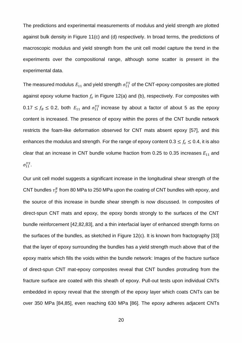
The predictions and experimental measurements of modulus and yield strength are plotted
against bulk density in Figure 11(c) and (d) respectively. In broad terms, the predictions of
macroscopic modulus and yield strength from the unit cell model capture the trend in the
experiments over the compositional range, although some scatter is present in the
experimental data.
The measured modulus 𝐸11 and yield strength 𝜎11𝑌𝑆 of the CNT-epoxy composites are plotted
against epoxy volume fraction 𝑓𝑒 in Figure 12(a) and (b), respectively. For composites with
0.17 ≤ 𝑓𝐵 ≤ 0.2, both 𝐸11 and 𝜎11𝑌𝑆 increase by about a factor of about 5 as the epoxy
content is increased. The presence of epoxy within the pores of the CNT bundle network
restricts the foam-like deformation observed for CNT mats absent epoxy [57], and this
enhances the modulus and strength. For the range of epoxy content 0.3 ≤ 𝑓𝑒 ≤ 0.4, it is also
clear that an increase in CNT bundle volume fraction from 0.25 to 0.35 increases 𝐸11 and
𝜎11𝑌𝑆.
Our unit cell model suggests a significant increase in the longitudinal shear strength of the
CNT bundles 𝜏𝑦𝐵 from 80 MPa to 250 MPa upon the coating of CNT bundles with epoxy, and
the source of this increase in bundle shear strength is now discussed. In composites of
direct-spun CNT mats and epoxy, the epoxy bonds strongly to the surfaces of the CNT
bundle reinforcement [42,82,83], and a thin interfacial layer of enhanced strength forms on
the surfaces of the bundles, as sketched in Figure 12(c). It is known from fractography [33]
that the layer of epoxy surrounding the bundles has a yield strength much above that of the
epoxy matrix which fills the voids within the bundle network: Images of the fracture surface
of direct-spun CNT mat-epoxy composites reveal that CNT bundles protruding from the
fracture surface are coated with this sheath of epoxy. Pull-out tests upon individual CNTs
embedded in epoxy reveal that the strength of the epoxy layer which coats CNTs can be
over 350 MPa [84,85], even reaching 630 MPa [86]. The epoxy adheres adjacent CNTs

21
within the outer layer of the bundle, and thereby increases the bundle longitudinal shear
strength. Note that this effect is modelled in the 2D context by increasing the shear strength
of the CNT bundles, 𝜏𝑦𝐵.
5. Concluding discussion
The modulus and strength of CNT-polymer composites as reported in the literature vary over
several orders of magnitude, and are sensitive to both composition and microstructure.
However, all reported data for the modulus, strength, electrical conductivity and thermal
conductivity of CNT-polymer composites are much below those of individual CNTs.
In the present study, composites were manufactured by infiltration of direct-spun CNT mats
with solutions of epoxy and acetone. Following curing, the composition of the manufactured
composites varied widely; the volume fraction of CNT bundles varied between 0.11 and 0.35,
the volume fraction of epoxy from 0.01 to 0.79, and the porosity ranged from 0.10 to 0.82.
The epoxy content in the cured composite increased with the concentration of epoxy in the
infiltration solution; the application of a pressure 𝑃 = 10 MPa in the through-thickness
direction after infiltration was used to attain higher CNT volume fractions. The epoxy matrix
does not penetrate the CNT bundles, but progressively fills the pores between the CNT
bundles as the epoxy volume fraction increases.
The modulus, yield strength and ultimate strength of the CNT mat-epoxy composites are
significantly above those of the dry CNT mat or cured epoxy. By suitable choice of
composition, composites exhibit an ultimate strength of 410 MPa, and modulus of almost 30
GPa. Both values represent an increase in over an order of magnitude compared to the
properties of the as-received CNT mat. The measured electrical conductivity of the mats

22
and composites scale linearly with CNT volume fraction and is insensitive to the epoxy
content.
The CNT-epoxy composite is idealised as a periodic honeycomb network in finite element
simulations. The model is able to describe the degree of elastic and plastic anisotropy of the
composite and the dependence of modulus and yield strength upon composition. By suitable
correlation of the predicted and measured yield strengths of the composite, the inferred
shear strength of a bundle is found to rise from 80 MPa in the absence of epoxy to 250 MPa
when epoxy is present. These values are consistent with those reported in the literature. We
deduce from comparison of measured composite properties against composition, and via
simulation, that the properties of the composite are sensitive to the coating of CNT bundles
with an interfacial layer of high strength epoxy, the epoxy volume fraction within the pores,
and the CNT bundle volume fraction.
Acknowledgements
W. Tan and J.C. Stallard contributed equally to this work. The authors would like to gratefully
acknowledge the funding from the EPSRC project ‘Advanced Nanotube Application and
Manufacturing (ANAM) Initiative’ under Grant No. EP/M015211/1, and for financial support
from the ERC ‘Multi-phase Lattice Materials’ (MULTILAT) under Grant No. 669764. The
authors would also like to acknowledge Tortech Nano Fibers Ltd for supplying CNT mat
material.
References
[1] M.F.L. De Volder, S.H. Tawfick, R.H. Baughman, A.J. Hart, Carbon Nanotubes: Present and Future Commercial Applications, Science. 339 (6119) (2013) 535–539.
[2] T.W. Chou, L. Gao, E.T. Thostenson, Z. Zhang, J.H. Byun, An assessment of the science and technology of carbon nanotube-based fibers and composites, Compos. Sci. Technol. 70 (1) (2010) 1–19.
[3] B. Peng, M. Locascio, P. Zapol, S. Li, S.L. Mielke, G.C. Schatz, H.D. Espinosa,
23
Measurements of near-ultimate strength for multiwalled carbon nanotubes and irradiation-induced crosslinking improvements, Nat. Nanotechnol. 3 (10) (2008) 626–631.
[4] E. Pop, D. Mann, Q. Wang, K. Goodson, H. Dai, Thermal Conductance of an Individual Single-Wall Carbon Nanotube above Room Temperature, Nano Lett. 6 (1) (2006) 96–100.
[5] T.T. Ebbesen, T. W., Lezec H. J., Hiura H., Bennett J. W., Ghaemi H. F, Electrical conductivity of individual carbon nanotubes, Nature. 382 (1996) 54–56.
[6] M. Kumar, Y. Ando, Chemical vapor deposition of carbon nanotubes: a review on growth mechanism and mass production., J. Nanosci. Nanotechnol. 10 (6) (2010) 3739–3758.
[7] L. Vaisman, H.D. Wagner, G. Marom, The role of surfactants in dispersion of carbon nanotubes, Adv. Colloid Interface Sci. 128–130 (2006) 37–46.
[8] J.B. Bai, A. Allaoui, Effect of the length and the aggregate size of MWNTs on the improvement efficiency of the mechanical and electrical properties of nanocomposites-experimental investigation, Compos. Part A. 34 (2003) 689–694.
[9] K.P. Ryan, M. Cadek, V. Nicolosi, D. Blond, M. Ruether, G. Armstrong, H. Swan, A. Fonseca, J.B. Nagy, W.K. Maser, W.J. Blau, J.N. Coleman, Carbon nanotubes for reinforcement of plastics? A case study with poly(vinyl alcohol), Compos. Sci. Technol. 67 (2007) 1640–1649.
[10] J. Zhu, J.D. Kim, H. Peng, J.L. Margrave, V.N. Khabashesku, E. V. Barrera, Improving the dispersion and integration of single-walled carbon nanotubes in epoxy composites through functionalization, Nano Lett. 3 (8) (2003) 1107–1113.
[11] B. Vigolo, Macroscopic Fibers and Ribbons of Oriented Carbon Nanotubes, Science. 290 (5495) (2000) 1331–1334.
[12] P. Miaudet, S. Badaire, M. Maugey, A. Derré, V. Pichot, P. Launois, P. Poulin, C. Zakri, Hot-drawing of single and multiwall carbon nanotube fibers for high toughness and alignment, Nano Lett. 5 (11) (2005) 2212–2215.
[13] J. Meng, Y. Zhang, K. Song, M.L. Minus, Forming crystalline polymer-nano interphase structures for high-modulus and high-tensile/strength composite fibers, Macromol. Mater. Eng. 299 (2) (2014) 144–153.
[14] J.N. Coleman, W.J. Blau, A.B. Dalton, E. Munoz, S. Collins, B.G. Kim, J. Razal, M. Selvidge, G. Vieiro, R.H. Baughman, Improving the mechanical properties of single-walled carbon nanotube sheets by intercalation of polymeric adhesives, Appl. Phys. Lett. 82 (11) (2003) 1682–1684.
[15] G.T. Pham, Y.-B. Park, S. Wang, Z. Liang, B. Wang, C. Zhang, P. Funchess, L. Kramer, Mechanical and electrical properties of polycarbonate nanotube buckypaper composite sheets, Nanotechnology. 19 (32) (2008) 325705.
[16] P.E. Lopes, F. van Hattum, C.M.C. Pereira, P.J.R.O. Novoa, S. Forero, F. Hepp, L. Pambaguian, High CNT content composites with CNT Buckypaper and epoxy resin matrix: Impregnation behaviour composite production and characterization, Compos. Struct. 92 (6) (2010) 1291–1298.
[17] A.M. Díez-Pascual, J. Guan, B. Simard, M.A. Gómez-Fatou, Poly(phenylene sulphide) and poly(ether ether ketone) composites reinforced with single-walled carbon nanotube buckypaper: II- Mechanical properties, electrical and thermal conductivity, Compos. Part A Appl. Sci. Manuf. 43 (2012) 1007–1015.
[18] B.L. Wardle, D.S. Saito, E.J. García, A.J. Hart, R.G. de Villoria, E.A. Verploegen, Fabrication and Characterization of Ultrahigh-Volume- Fraction Aligned Carbon Nanotube-Polymer Composites, Adv. Mater. 20 (14) (2008) 2707–2714.
[19] D. Wang, P. Song, C. Liu, W. Wu, S. Fan, Highly oriented carbon nanotube papers made of aligned carbon nanotubes, Nanotechnology. 19 (7) (2008) 075609.
[20] P.D. Bradford, X. Wang, H. Zhao, J.P. Maria, Q. Jia, Y.T. Zhu, A novel approach to fabricate

24
high volume fraction nanocomposites with long aligned carbon nanotubes, Compos. Sci. Technol. 70 (13) (2010) 1980–1985.
[21] M. Mecklenburg, D. Mizushima, N. Ohtake, W. Bauhofer, B. Fiedler, K. Schulte, On the manufacturing and electrical and mechanical properties of ultra-high wt.% fraction aligned MWCNT and randomly oriented CNT epoxy composites, Carbon N. Y. 91 (2015) 275–290.
[22] Q.F. Cheng, J.P. Wang, J.J. Wen, C.H. Liu, K.L. Jiang, Q.Q. Li, S.S. Fan, Carbon nanotube/epoxy composites fabricated by resin transfer molding, Carbon N. Y. 48 (1) (2010) 260–266.
[23] Y.-N. Liu, M. Li, Y. Gu, Y. Zhang, Q. Li, Z. Zhang, Ultrastrong carbon nanotube/ bismaleimide composite film with super-aligned and tightly packing structure, Compos. Sci. Technol. 117 (2015) 176–182.
[24] A.E. Bogdanovich, P.D. Bradford, Carbon nanotube yarn and 3-D braid composites. Part I: Tensile testing and mechanical properties analysis, Compos. Part A Appl. Sci. Manuf. 41 (2) (2010) 230–237.
[25] Q. Cheng, J. Wang, K. Jiang, Q. Li, S. Fan, Fabrication and properties of aligned multiwalled carbon nanotube-reinforced epoxy composites, J. Mater. Res. 23 (11) (2008) 2975–2983.
[26] W. Liu, X. Zhang, G. Xu, P.D. Bradford, X. Wang, H. Zhao, Y. Zhang, Q. Jia, F.G. Yuan, Q. Li, Y. Qiu, Y. Zhu, Producing superior composites by winding carbon nanotubes onto a mandrel under a poly(vinyl alcohol) spray, Carbon N. Y. 49 (14) (2011) 4786–4791.
[27] X. Wang, Q. Jiang, W. Xu, W. Cai, Y. Inoue, Y. Zhu, Effect of carbon nanotube length on thermal, electrical and mechanical properties of CNT/bismaleimide composites, Carbon N. Y. 53 (2013) 145–152.
[28] S. Li, X. Zhang, J. Zhao, F. Meng, G. Xu, Z. Yong, J. Jia, Z. Zhang, Q. Li, Enhancement of carbon nanotube fibres using different solvents and polymers, Compos. Sci. Technol. 72 (12) (2012) 1402–1407.
[29] X. Yao, B.G. Falzon, S.C. Hawkins, S. Tsantzalis, Aligned carbon nanotube webs embedded in a composite laminate: A route towards a highly tunable electro-thermal system, Carbon N. Y. 129 (2018) 486–494.
[30] Q. Cheng, J. Bao, J. Park, Z. Liang, C. Zhang, B. Wang, High mechanical performance composite conductor: Multi-walled carbon nanotube sheet/bismaleimide nanocomposites, Adv. Funct. Mater. 19 (20) (2009) 3219–3225.
[31] Q. Cheng, B. Wang, C. Zhang, Z. Liang, Functionalized carbon-nanotube sheet/bismaleimide nanocomposites: Mechanical and electrical performance beyond carbon-fiber composites, Small. 6 (6) (2010) 763–767.
[32] R.J. Mora, J.J. Vilatela, A.H. Windle, Properties of composites of carbon nanotube fibres, Compos. Sci. Technol. 69 (2008) 1558–1563.
[33] A. Mikhalchan, T. Gspann, A. Windle, Aligned carbon nanotube–epoxy composites: the effect of nanotube organization on strength, stiffness, and toughness, J. Mater. Sci. 51 (22) (2016) 10005–10025.
[34] H.S. Kim, Processing and characterization of carbon nanotube mat/epoxy composites, Met. Mater. Int. 17 (5) (2011) 697–704.
[35] M. Li, Z. Wang, Q. Liu, S. Wang, Y. Gu, Y. Li, Z. Zhang, Carbon nanotube film/epoxy composites with high strength and toughness, Polym. Compos. 38 (3) (2017) 588–596.
[36] T.H. Nam, K. Goto, Y. Yamaguchi, E.V.A. Premalal, Y. Shimamura, Y. Inoue, S. Arikawa, S. Yoneyama, S. Ogihara, Improving mechanical properties of high volume fraction aligned multi-walled carbon nanotube/epoxy composites by stretching and pressing, Compos. Part B Eng. 85 (2016) 15–23.
[37] M.F. Yu, O. Lourie, M.J. Dyer, K. Moloni, T.F. Kelly, R.S. Ruoff, Strength and breaking mechanism of multiwalled carbon nanotubes under tensile load, Science. 287 (5453) (2000)

25
637–640.
[38] E.T. Thostenson, Z. Ren, T.-W. Chou, Advances in the science and technology of carbon nanotubes and their composites: a review, Compos. Sci. Technol. 61 (13) (2001) 1899–1912.
[39] N. Hiremath, J. Mays, G. Bhat, Recent Developments in Carbon Fibers and Carbon Nanotube-Based Fibers : A Review Recent Developments in Carbon Fibers and Carbon, Polym. Rev. 57 (2) (2016) 339–368.
[40] H. Qian, E.S. Greenhalgh, M.S.P. Shaffer, A. Bismarck, Carbon nanotube-based hierarchical composites: a review, J. Mater. Chem. 20 (23) (2010) 4751.
[41] Z. Spitalsky, D. Tasis, K. Papagelis, C. Galiotis, Carbon nanotube–polymer composites: Chemistry, processing, mechanical and electrical properties, Prog. Polym. Sci. 35 (3) (2010) 357–401.
[42] Y. Liu, S. Kumar, Polymer/Carbon Nanotube Nano Composite Fibers–A Review, ACS Appl. Mater. Interfaces. 6 (9) (2014) 6069–6087.
[43] J.H. Du, J. Bai, H.M. Cheng, The present status and key problems of carbon nanotube based polymer composites, Express Polym. Lett. 1 (5) (2007) 253–273.
[44] F.T. Fisher, R.D. Bradshaw, L.C. Brinson, Fiber waviness in nanotube-reinforced polymer composites-I: Modulus predictions using effective nanotube properties, Compos. Sci. Technol. 63 (11) (2003) 1689–1703.
[45] X. Zhang, W. Tan, F. Smail, M. De Volder, N. Fleck, A. Boies, High-fidelity characterization on anisotropic thermal conductivity of carbon nanotube sheets and on their effects of thermal enhancement of nanocomposites, Nanotechnology. 29 (2018) 365708.
[46] F. Gardea, D.C. Lagoudas, Characterization of electrical and thermal properties of carbon nanotube/epoxy composites, Compos. Part B Eng. 56 (2014) 611–620.
[47] L. Gao, X. Zhou, Y. Ding, Effective thermal and electrical conductivity of carbon nanotube composites, Chem. Phys. Lett. 434 (4–6) (2007) 297–300.
[48] W. Cui, F. Du, J. Zhao, W. Zhang, Y. Yang, X. Xie, Y.W. Mai, Improving thermal conductivity while retaining high electrical resistivity of epoxy composites by incorporating silica-coated multi-walled carbon nanotubes, Carbon N. Y. 49 (2) (2011) 495–500.
[49] J.G. Park, Q. Cheng, J. Lu, J. Bao, S. Li, Y. Tian, Z. Liang, C. Zhang, B. Wang, Thermal conductivity of MWCNT/epoxy composites: The effects of length, alignment and functionalization, Carbon N. Y. 50 (6) (2012) 2083–2090.
[50] Q. Jiang, X. Wang, Y. Zhu, D. Hui, Y. Qiu, Mechanical, electrical and thermal properties of aligned carbon nanotube/polyimide composites, Compos. Part B Eng. 56 (2014) 408–412.
[51] A. Moisala, Q. Li, I.A. Kinloch, A.H. Windle, Thermal and electrical conductivity of single- and multi-walled carbon nanotube-epoxy composites, Compos. Sci. Technol. 66 (10) (2006) 1285–1288.
[52] F.H. Gojny, M.H.G. Wichmann, B. Fiedler, I.A. Kinloch, W. Bauhofer, A.H. Windle, K. Schulte, Evaluation and identification of electrical and thermal conduction mechanisms in carbon nanotube/epoxy composites, Polymer (Guildf). 47 (6) (2006) 2036–2045.
[53] J.J. Vilatela, R. Khare, A.H. Windle, The hierarchical structure and properties of multifunctional carbon nanotube fibre composites, Carbon N. Y. 50 (3) (2012) 1227–1234.
[54] E.S. Choi, J.S. Brooks, D.L. Eaton, M.S. Al-Haik, M.Y. Hussaini, H. Garmestani, D. Li, K. Dahmen, Enhancement of thermal and electrical properties of carbon nanotube polymer composites by magnetic field processing, J. Appl. Phys. 94 (9) (2003) 6034–6039.
[55] S. Nardecchia, D. Carriazo, M.L. Ferrer, M.C. Gutiérrez, F. del Monte, Three dimensional macroporous architectures and aerogels built of carbon nanotubes and/or graphene: synthesis and applications, Chem. Soc. Rev. 42 (2) (2013) 794–830.

26
[56] J.N. Wang, X.G. Luo, T. Wu, Y. Chen, High-strength carbon nanotube fibre-like ribbon with high ductility and high electrical conductivity., Nat. Commun. 5 (2014) 3848.
[57] J.C. Stallard, W. Tan, F.R. Smail, T.S. Gspann, A.M. Boies, N.A. Fleck, The mechanical and electrical properties of direct-spun carbon nanotube mats, Extrem. Mech. Lett. 21 (2018) 65–75.
[58] K.L. Stano, K. Koziol, M. Pick, M.S. Motta, A. Moisala, J.J. Vilatela, S. Frasier, A.H. Windle, Direct spinning of carbon nanotube fibres from liquid feedstock, Int. J. Mater. Form. 1 (2) (2008) 59–62.
[59] J.J. Vilatela, A.H. Windle, Yarn-like carbon nanotube fibers, Adv. Mater. 22 (44) (2010) 4959–4963.
[60] D. Janas, K.K. Koziol, Carbon nanotube fibers and films: synthesis, applications and perspectives of the direct-spinning method, Nanoscale. 8 (2016) 19475–19490.
[61] E.T. Thostenson, T.-W. Chou, On the elastic properties of carbon nanotube-based composites: modelling and characterization, J. Phys. D. Appl. Phys. 36 (2003) 573–582.
[62] G.D. Dean, P. Turner, The elastic properties of carbon fibres and their composites, Composites. 4 (4) (1973) 174–180.
[63] T. Bru, P. Hellström, R. Gutkin, D. Ramantani, G. Peterson, Characterisation of the mechanical and fracture properties of a uni-weave carbon fibre/epoxy non-crimp fabric composite, Data Br. 6 (2016) 680–695.
[64] C. Qian, L.T. Harper, T.A. Turner, N.A. Warrior, Notched behaviour of discontinuous carbon fibre composites: Comparison with quasi-isotropic non-crimp fabric, Compos. Part A Appl. Sci. Manuf. 42 (3) (2011) 293–302.
[65] S. Hernández, F. Sket, C. González, J. Llorca, Optimization of curing cycle in carbon fiber-reinforced laminates: Void distribution and mechanical properties, Compos. Sci. Technol. 85 (2013) 73–82.
[66] M. Sohi, H. Hahn, J. Williams, The Effect of Resin Toughness and Modulus on Compressive Failure Modes of Quasi-Isotropic Graphite/Epoxy Laminates, ASTM STP 937. (1987) 37–60.
[67] W. Tan, B.G. Falzon, Modelling the crush behaviour of thermoplastic composites, Compos. Sci. Technol. 134 (2016) 57–71.
[68] D.-L. Shi, X.-Q. Feng, Y.Y. Huang, K.-C. Hwang, H. Gao, The Effect of Nanotube Waviness and Agglomeration on the Elastic Property of Carbon Nanotube-Reinforced Composites, J. Eng. Mater. Technol. 126 (3) (2004) 250.
[69] Y.-L. Li, I.A. Kinloch, A.H. Windle, Direct Spinning of Carbon Nanotube Fibers from Chemical Vapor Deposition Synthesis, Science. 304 (5668) (2004) 276–278.
[70] C. Hoecker, F. Smail, M. Bajada, M. Pick, A. Boies, Catalyst nanoparticle growth dynamics and their influence on product morphology in a CVD process for continuous carbon nanotube synthesis, Carbon N. Y. 96 (2016) 116–124.
[71] B. Alemán, V. Reguero, B. Mas, J.J. Vilatela, Strong Carbon Nanotube Fibers by Drawing Inspiration from Polymer Fiber Spinning, ACS Nano. 9 (7) (2015) 7392–7398.
[72] B. Prenitzer, L. Giannuzzi, K. Newman, S. Brown, R. Irwin, F. Stevie, T. Shofner, Transmission electron microscope specimen preparation of Zn powders using the focused ion beam lift-out technique, Metall. Mater. Trans. A. 29 (9) (1998) 2399–2406.
[73] J.-P. Salvetat, G. Briggs, J.-M. Bonard, R. Bacsa, A. Kulik, T. Stöckli, N. Burnham, L. Forró, Elastic and Shear Moduli of Single-Walled Carbon Nanotube Ropes, Phys. Rev. Lett. 82 (5) (1999) 944–947.
[74] A. Kis, G. Csányi, J.-P. Salvetat, T.-N. Lee, E. Couteau, A.J. Kulik, W. Benoit, J. Brugger, L. Forró, Reinforcement of single-walled carbon nanotube bundles by intertube bridging, Nat. Mater. 3 (3) (2004) 153–157.

27
[75] W. Ding, L. Calabri, K.M. Kohlhaas, X. Chen, D.A. Dikin, R.S. Ruoff, Modulus, fracture strength, and brittle vs. plastic response of the outer shell of arc-grown multi-walled carbon nanotubes, Exp. Mech. 47 (1) (2007) 25–36.
[76] O. V. Kharissova, B.I. Kharisov, Variations of interlayer spacing in carbon nanotubes, RSC Adv. 4 (58) (2014) 30807–30815.
[77] J.Z. Liu, Q.-S. Zheng, L.-F. Wang, Q. Jiang, Mechanical properties of single-walled carbon nanotube bundles as bulk materials, J. Mech. Phys. Solids. 53 (1) (2005) 123–142.
[78] J.P. Lu, Elastic properties of carbon nanotubes and nanoropes, Phys. Rev. Lett. 79 (9) (1997) 1297–1300.
[79] E. Saether, S.J.V. Frankland, R.B. Pipes, Transverse mechanical properties of single-walled carbon nanotube crystals. Part I: Determination of elastic moduli, Compos. Sci. Technol. 63 (11) (2003) 1543–1550.
[80] R. Hill, A Theory of the Yielding and Plastic Flow of Anisotropic Metals, Proc. R. Soc. A Math. Phys. Eng. Sci. 193 (1033) (1948) 281–297.
[81] M. Naraghi, T. Filleter, A. Moravsky, M. Locascio, R.O. Loutfy, H.D. Espinosa, A Multiscale Study of High Performance Double-Walled Nanotube−Polymer Fibers, ACS Nano. 4 (11) (2010) 6463–6476.
[82] H.G. Chae, M.L. Minus, S. Kumar, Oriented and exfoliated single wall carbon nanotubes in polyacrylonitrile, Polymer (Guildf). 47 (10) (2006) 3494–3504.
[83] J.N. Coleman, M. Cadek, R. Blake, V. Nicolosi, K.P. Ryan, C. Belton, A. Fonseca, J.B. Nagy, Y.K. Gun’ko, W.J. Blau, High-performance nanotube-reinforced plastics: Understanding the mechanism of strength increase, Adv. Funct. Mater. (2004).
[84] X. Chen, M. Zheng, C. Park, C. Ke, Direct measurements of the mechanical strength of carbon nanotube-poly(methyl methacrylate) interfaces, Small. 9 (19) (2013) 3345–3351.
[85] C.A. Cooper, S.R. Cohen, A.H. Barber, H.D. Wagner, Detachment of nanotubes from a polymer matrix, Appl. Phys. Lett. 81 (20) (2002) 3873–3875.
[86] X. Chen, L. Zhang, M. Zheng, C. Park, X. Wang, C. Ke, Quantitative nanomechanical characterization of the van der Waals interfaces between carbon nanotubes and epoxy, Carbon N. Y. 82 (2015) 214–228.

28
Graphical abstract

29
Figures
Figure 1: Classes of CNT polymer composites.

30
Figure 2: The mechanical properties (a) and electrical and thermal properties (b) of CNTs and CNT-polymer composites. (c) Composition diagram for CNT foams, CNT fibres/mats,
and CNT-epoxy composites. (d) The moduli of CNT-epoxy and CFRP composites, normalised by the reinforcement modulus, is plotted against fibre volume fraction. Data are
taken from [8-67] and from the present study.

31
Figure 3: The hierarchical microstructure of direct-spun CNT mats.

32
Figure 4: Methodology of CNT-epoxy composite manufacture.

33
Figure 5: (a) Density 𝜌 of dry mat and cured composites, plotted against the concentration of epoxy by weight 𝜙 for the infiltration solution used in manufacture. The volume fractions 𝑓 of CNT bundles, epoxy and air in the cured composite are plotted against bulk composite
density in (b) for samples manufactured with a consolidation pressure 𝑃 = 0.1 MPa, and in (c) for samples subjected to a 10 MPa pressure prior to vacuum.

34
Figure 6: Plan-view of (a) CNT mat, (b) composite (5) and (c) composite (9). FIB-milled cross-sections for (d) dry mat, (e) composite (5) and (f) composite (9). (g) Plan view of a
CNT bundle in dry mat; (h) FIB-milled cross-section of composite (9), with (i) distribution of Silicon-tagged epoxy. Images (a)-(e) taken in SEM, (f)-(i) in TEM.

35
Figure 7: Specimen geometries, (a) for uniaxial tensile tests on CNT mat or CNT-epoxy composites, (b) epoxy dog-bone sample, with thickness 6 mm. (c) Four-point probe
method used to measure the electrical conductivity. All dimensions are in mm.

36
Figure 8: Stress versus strain response of composites and mat (a) in 3 orientations, (b) manufactured at 𝑃 = 0.1 MPa. Materials manufactured with 𝑃 = 1 MPa and 𝑃 = 10 MPa
are compared in (c). Dependence upon density 𝜌 of modulus 𝐸 in (d), yield strength 𝜎𝑌𝑆 in
(e), and ultimate tensile strength 𝜎𝑈𝑇𝑆 in (f) for the composites, direct-spun mat, and epoxy.

37
Figure 9: The planar honeycomb unit cell idealisation of (a) CNT mat and (b) CNT-epoxy composite microstructure with 𝜔 = 45°. Details of the simulation setup and boundary conditions for the repeating unit cell analysed are shown in (c); note the variation of
material orientation around the node.
38
Figure 10: (a) The electrical conductivity of the CNT mat (1) and CNT-epoxy composite (9) in different directions. (b) Electrical conductivity in the principal material direction plotted
against CNT volume fraction. (c) Piezoresistive and unloading response, showing evolution of sample resistance with strain for dry mat and composite. The moduli upon
unload are plotted against the applied tensile strain in (d).

39
Figure 11: The ratios of the predicted principal and transverse moduli are plotted as a function of 𝜔 in (a), alongside the experimentally measured values. Measured and
predicted uniaxial stress-strain responses are plotted in (b), and the modulus and yield strengths of manufactured CNT mat and composites in the principal material direction are
compared with the unit cell predictions in (c) and (d) respectively.

40
Figure 12: The measured modulus (a) and yield strength (b) for CNT-epoxy composites, as a function of composition. (c) CNT bundles are coated with an interfacial layer of
enhanced yield strength upon infiltration.

41
Tables
Table 1: Composition of direct-spun CNT mat and CNT-epoxy composites as a function of the process parameters
Sample
label
Epoxy
concentration
Consolidation
pressure Average density Average volume fraction
𝜙 𝑃 (MPa) 𝜌 (kg/m3) 𝑓𝐵 𝑓𝑒 𝑓𝑎
(1) 0 0.1 234 0.15 0 0.85
(1h) 0 10 296 0.19 0 0.81
(2) 0.001 0.1 276 0.17 0.01 0.82
(3) 0.01 0.1 330 0.19 0.03 0.78
(4) 0.10 0.1 469 0.20 0.14 0.66
(5) 0.12 0.1 605 0.23 0.22 0.55
(5h) 0.12 10 811 0.29 0.32 0.39
(6) 0.17 0.1 771 0.25 0.34 0.41
(6h) 0.17 10 983 0.35 0.39 0.26
(7) 0.30 0.1 906 0.20 0.53 0.27
(8) 0.75 0.1 986 0.18 0.63 0.19
(9) 1 0.1 1060 0.11 0.79 0.10
(10) 1 0.1 1120 0 1 0
(11) 0.50 0.1 1120 0 1 0

42
Table 2: Material constants used in the finite element analysis
Material Material constants
CNT
bundle
𝐸11𝐵 = 680 GPa, 𝐸22
𝐵 = E33B = 50 GPa
𝐺12𝐵 = G23
B = G13B = 9.5 GPa, 𝜈12 = ν13 = 0.3
𝜎11𝐵 = 3700 MPa
𝜎22𝐵 = 𝜎33
𝐵 = 𝜏𝑦𝐵 = 80 MPa (CNT bundle absent epoxy), 250 MPa (epoxy
coated CNT bundle)
𝜏12𝐵 = 𝜏23
𝐵 = 𝜏13𝐵 = 𝜏𝑦
𝐵
Epoxy 𝐸𝑒 = 3.0 GPa, 𝜈𝑒 = 0.3, 𝜎𝑦𝑒 = 60 MPa

43
Supplementary Information for
THE MECHANICAL AND ELECTRICAL PROPERTIES OF
DIRECT-SPUN CARBON NANOTUBE MAT-EPOXY
COMPOSITES
Wei Tan, Joe C. Stallard, Fiona R. Smail, Adam M. Boies, Norman A. Fleck*
Address: Engineering Department, University of Cambridge, Trumpington Street,
Cambridge, CB2 1PZ, UK.
*Corresponding author. Tel: +44 (0)1223 748240. Email: [email protected] (N.A.
Fleck)
1. Axial elastic modulus of carbon fibres used in Figure 2
The value of reinforcement modulus 𝐸𝑅 used in normalisation of the longitudinal modulus of
long fibre carbon fibre composites Figure 2(d) are given in Table S1.
Table S1: Axial elastic modulus of carbon fibres
CFRP laminate Ref. Carbon fibre Resin 𝐸𝑅 (GPa)
Unidirectional
[1] Modmor type I LY558 epoxy 410
[1] Modmor type II LY558 epoxy 240
[1] Rolls Royce fibres LY558 epoxy 200
[2] Tenax HS45 fibre LY556 epoxy 240
Quasi-isotropic
[3] Sigmatex 450gsm Gurit Prime 20LV 212
[4,5] AS4 8552, PEKK 231
[6] T300 5208,BP907,4901/(m)MDA 230
[6] T700 5208,BP907,4901/(m)MDA 230

44
2. Thickness of mat and composites
The dependence of thickness 𝑡 upon composite density 𝜌 is plotted in Figure S1. The range
and mean values are plotted for ten thickness measurements over the sample length.
Figure S1: Measured thickness of CNT mat and composites
3. Estimation of the axial modulus and yield strength of a CNT bundle
The walls of multi-walled CNTs in the direct-spun mat studied herein are comprised of a
number of concentric seamless cylindrical graphene layers, with typical spacing between
the layers of 𝑑 = 0.335 nm in the radial direction [7]. Upon calculating the modulus of a

45
graphene layer based upon an assumed layer thickness of 𝑑, the longitudinal modulus of
the CNT walls according to literature is 𝐸𝑤 = 1 TPa [8,9].
The CNT wall density derives from the areal density of carbon atoms in each wall layer Ρ𝑆 =
3.82 x 10¹⁹ m-2 [10], the mass of each carbon atom 𝑚𝑐 = 12𝑢, where the atomic mass unit
𝑢 = 1.66×10⁻²⁷ kg, and the spacing between each wall layer 𝑑, as follows:
𝜌𝑤 =12 ∙ 𝑢 × Ρ𝑆
𝑑 ,
where 𝑢 = 1.66×10⁻²⁷ kg is the atomic mass unit. This yields a wall density 𝜌𝑤 = 2.3×10³
kg/m3.
In direct-spun CNT materials, measurements of the individual CNTs have shown that they
are very long, up to 1 mm in length [11]. Therefore, the CNT lengths are far greater than the
length of an individual CNT bundle strut between junctions, which are typically much less
than 1 μm. It is therefore reasonable to assume that the CNTs are continuous along the
lengths of CNT bundle struts for estimation of the longitudinal bundle modulus.
4. Geometry of CNT-epoxy unit cells used in simulation
Images of the unit cells of CNT bundles, epoxy and air used in simulation are given in Figure
S2. The ratio of the CNT bundle thickness to the length of unit cell struts 𝑡𝐵/𝑙 and the ratio
of the epoxy layer thickness to unit cell strut length 𝑡𝑒/𝑙 are recorded in Table S2 for each
of the simulated unit cells. The ratios of the fillet radii to bundle thickness, 𝑅1/𝑡𝐵 and 𝑅2/𝑡𝐵,
are 2.0 and 0.54 respectively, with the exception of composite 6(h), where an elliptical pore
was used instead, see Figure S2.

46
Figure S2: FE models of dry mat and CNT-epoxy composites
Table S2: Normliased values of CNT bundle thickness, epoxy layer thickness and fillet
radii of junctions betweeen the struts for FE simulation
Material 𝑡𝐵/𝑙 𝑡𝑒/𝑙
(1) 0.12 0
(1h) 0.16 0
(2) 0.15 0.019
(3) 0.17 0.013
(4) 0.17 0.069
(5) 0.18 0.11
(5h) 0.25 0.23
(6) 0.21 0.23
(6h) 0.29 0.29
(7) 0.17 0.31
(8) 0.15 0.36
(9) 0.09 0.48

47
References:
[1] G.D. Dean, P. Turner, The elastic properties of carbon fibres and their composites, Composites. 4 (1973) 174–180. doi:10.1016/0010-4361(73)90109-2.
[2] T. Bru, P. Hellström, R. Gutkin, D. Ramantani, G. Peterson, Characterisation of the mechanical and fracture properties of a uni-weave carbon fibre/epoxy non-crimp fabric composite, Data Br. 6 (2016) 680–695. doi:10.1016/J.DIB.2016.01.010.
[3] C. Qian, L.T. Harper, T.A. Turner, N.A. Warrior, Notched behaviour of discontinuous carbon fibre composites: Comparison with quasi-isotropic non-crimp fabric, Compos. Part A Appl. Sci. Manuf. 42 (2011) 293–302. doi:10.1016/J.COMPOSITESA.2010.12.001.
[4] S. Hernández, F. Sket, C. González, J. Llorca, Optimization of curing cycle in carbon fiber-reinforced laminates: Void distribution and mechanical properties, Compos. Sci. Technol. 85 (2013) 73–82. doi:10.1016/j.compscitech.2013.06.005.
[5] W. Tan, B.G. Falzon, Modelling the crush behaviour of thermoplastic composites, Compos. Sci. Technol. 134 (2016) 57–71. doi:10.1016/j.compscitech.2016.07.015.
[6] M. Sohi, H. Hahn, J. Williams, The Effect of Resin Toughness and Modulus on Compressive Failure Modes of Quasi-Isotropic Graphite/Epoxy Laminates, ASTM STP 937. (1987) 37–60. doi:10.1520/STP24370S.
[7] O. V. Kharissova, B.I. Kharisov, Variations of interlayer spacing in carbon nanotubes, RSC Adv. 4 (2014) 30807–30815. doi:10.1039/C4RA04201H.
[8] B. Peng, M. Locascio, P. Zapol, S. Li, S.L. Mielke, G.C. Schatz, H.D. Espinosa, Measurements of near-ultimate strength for multiwalled carbon nanotubes and irradiation-induced crosslinking improvements, Nat. Nanotechnol. 3 (2008) 626–631. doi:10.1038/nnano.2008.211.
[9] W. Ding, L. Calabri, K.M. Kohlhaas, X. Chen, D.A. Dikin, R.S. Ruoff, Modulus, fracture strength, and brittle vs. plastic response of the outer shell of arc-grown multi-walled carbon nanotubes, Exp. Mech. 47 (2007) 25–36. doi:10.1007/s11340-006-9344-6.
[10] E. Pop, V. Varshney, A.K. Roy, Thermal properties of graphene: Fundamentals and applications, MRS Bull. 37 (2012) 1273–1281. doi:10.1557/mrs.2012.203.
[11] K. Koziol, J. Vilatela, A. Moisala, M. Motta, P. Cunniff, M. Sennett, A. Windle, High-performance carbon nanotube fiber, Science (80-. ). 318 (2007) 1892–1895. doi:10.1126/science.1147635.


![20140506034709PM_Maharashtra Engineering [Electrical- Mechanical] Services, Gr-B-Paper-2 [Electrical and Mechanical Engineering] (1)](https://img.dokumen.tips/doc/110x75/577cc0791a28aba71190397f/20140506034709pmmaharashtra-engineering-electrical-mechanical-services.jpg)