Embed Size (px)
Citation preview

SEPTEMBER 2018EXAMINATION OF MARINE ENGINEER
OFFICER Function: Maintenance & Repair at Management Level
MARINE ENGINEERING PRACTICETIME ALLOWED - 3 HOURS.
Instructions: -
1. Answer SIX questions only2. All Questions carry equal marks
3. Neatness in handwriting and clarity in expression carries weightage
4. Illustration of an Answer with clear sketches /diagram carries weightage
5. All unused pages of the answer script must be cancelled out by two lines (X) across the page
6. Write the full question before attempting to write the answer to same.
Q1. Describe TWO methods of tracing a superficial crack in a marine machinery component; Explain how propagation of a crack in a machinery component can be arrested.
Answer:- (A) Magna – flux crack detection :- Metal parts when they are machined and/or welded can become stressed during those processes. Those stresses can reveal themselves in the form of small fissures or cracks in the metal joints. These stress fractures at times may be difficult to see with the human eye. A method of employing small magnetic particles and a fluorescent dye was implemented to highlight any abnormalities of the machining and joining those metal parts.

Magnaflux testing can be used only on metal parts that can be magnetized. The size of the part can range from small ball bearings to entire aircraft frames. As long as the material can be coated with the dye solution that contains the small magnetic particles and that particular test piece can withstand a small magnetic field, the part can be magnafluxed.
Dye penetrant test :- 1. Dye penetrant testing is used to detect the presence of surface cracks in components.
2. The ideology to detect these cracks is by means of a dye usually highly colorful and less viscous that enables it to penetrate into cracks in the surfaces. This happens mainly due to the capillary action.
3. The dye tends to remain inside the crack, which is made to surface out by the use of appropriate chemicals thus indicating the size and structure of the crack.
Here’s how we practically carry out the dye penetrant testing. The dye penetrant kit basically constitutes of three chemicals in pressurized cans.
1. Cleaner – The cleaner is basically a thinning agent like thinner that tends to clean the surface where the testing is to be carried out. It is normally sprayed on the surface causing the greases and other dirt particles to disintegrate from the surface. The cleaner all by itself after doing the necessary cleaning action evaporates.
2. Penetrant: The penetrant is the highly colorful dye usually in bright color like red, etc. The penetrant is normally a less viscous liquid that enables it to penetrate into cracks; moreover it is the capillary action that causes the penetrant to be sucked inside the cracks.
3. Developer: The developer is basically an absorbent chemical quite similar to chalk powder for its absorption capabilities. The developer sprayed on top of the surface where the penetrant has already been

applied to tend to absorb the penetrant present in the cracks and indicates the same clearly to the eye.
Here's the procedure explaining the dye penetrant testing.
Precleaning: This is the most important and vital stage of the dye penetrant testing. The surface to be tested is to be free from grease, oil, paints, etc. Dust particles covering the area can be removed by using pressurized air. The materials that have the capability to stick to the surface like grease, oil, gum, diesel, etc. can be removed easily by means of the cleaner. The cleaner disintegrates the sticky particles on the surface and carries away the same while flowing away. Any residual cleaner left on the surface tends to get evaporated all by itself. The area cleaned using the cleaner is to be left to dry for about 5 to 6 minutes.Penetrant Application: The dye penetrant is now applied to the area where the cracks are to be determined. A dwelling period of about 10 to 15 minutes would be very much ideal for the penetrant to get itself settled inside the cracks present on the surface of the component.Penetrant Removal: The excess penetrant that is present on the surface is removed using lint free clothing soaked with the cleaner. Care needs to be taken to ensure that the cleaner does not flow on the surface. The excess penetrant needs to be wiped out of the surface very carefully. This basically requires a good amount of expertise.Developing: The developer is used to develop the penetrant present inside the cracks. Good amount of care needs to be taken by the user ensuring that no excess amount of developer is added to the surface. This may cause penetrant present inside the crack to be absorbed more quickly and distributed in the excess developer chemical. This can lead to an indication that no crack is present in the area.Inspection: The developer used properly tends to indicate the areas where cracks are present. Cracks present are indicates a bright spots usually the color of the penetrant. The developer normally tends to provide a white background for the same enabling the inspector to identify the crack immediately.

(B) A crack on any component on the surface can be arrested from further development by drilling two holes of dia greater than the width of the crack , one each at the ends of the crack to a depth slightly graeter than the depth of the crack. aafter drilling the holes the hole edges must be rounded using an oil stone.
Q2. With respect to the operation of two stage air compressor. Explain :A. The causes of occasional lifting of 2nd stage relief valve .B. Breakage of valve plates .C. Puncture of bursting disc of 1st stage intercooler .D. Noticeable reduction in capacity of the compressors over a period of time.
Answer:- (A) In a two-stage air compressor, the second stage relief valve is fitted after the second stage intercooler. The air leaving the second stage intercooler is to have a temperature of not more than 40 0 C if intercooling is efficient . If the intercooler is not cooling sufficiently the air entering the airbortle is hotter causing the air in the bottle to get heated . This results in higher pressure of air in the bottle causing a high back pressure on the air entering the bottle , which causes the relief valve to lift.
(B) Valve plates are subjected to smart opening and closing of the valves by the springs acting on the valves . If the springs are too stiff the impact of the valve plates on the seats can be heavy so causing them to break.
(C) The bursting disc of the ist stage intercooler occurs if the inter cooler tubes are leaking so that the cooler shell
containing the cooling water gets pressurised causing the disc to get punctured.
(D) Reduction in capacity is noticed by the larger time taken to fill the bottle from zero gauge pressure to full pressure as compared with the declared time in the manual.
The overall volumetric efficiency of the compressor has reduced caused by wear and deterioration as listed under.
wear and break of piston rings.Wear of liner bore.
Wear of main and bottom end bearings causing loss of volumetric efficiency,
Heavy scaling of inter coolers leading to poor heat transfer, resulting in reduction of mass of air entering the air bottle.
Q3. Enumerate the maintenance routines carried out for the proper functioning of the following systems: A. Water hyper mist system B. Smoke detection system C. Quick closing valves D. Fire hydrants and hoses.
AnswerA) Water hyper-mist system

(B) The smoke detection system , especially for cargo holds is simulated in the following manner:
* The test is to be conducted when the holds are empty preferably during a ballast passage.
* a long pole with a tray containing a smoke test bomb lighted is raised to the vicinity of the CO2 spreader fixed on the hold ceiling. There are normally 2 or four spreaders for each hold depending on the size of the hold

* The smoke from the bomb is sucked by the sensor panel fitted on the navigating bridge and the photo electric cell gets activated giving the alarm and light signal too. This test is repeated for all the spreaders located oin all the holds.
The smoke pipes leading to the indicator on the bridge must be blown through with compressed air regularly to clear the passages.
The photo cell may require cleaning by applying a felt cloth so that the passage of light through the lens is not restricted. Smoke adheres to the glass and hence this cleaning is necessary.(C) The quick closing valves are tested for remote operation from the control panel , and this routine is carried out on weekly basis. * Apart from this if it is an air operated system the actuating mechanism fitted on the valves must be checked for any air leakage or sluggish action and suitably corrected.(D) Fire hoses must be checked for damage and renewed if their canvas or flax covering is damaged during use. Hydrants must open and shut tight without the use of a wheel spanner and hence it should be made sure the hydrants don’t leak when ever deck water is being supplied for anchor duties. Such leaking hydrants must be overhauled. Bent spindles must be renewed, leaky glands repacked or tightened. Leaky joints must be renewed.

4 Abnormal vibration has been observed in a HFO purifier while in operation. Explain the areas you plan to investigate for rectifying the faults and put back the purifier back to normal operations keeping in view that no reduction in vibration has been noticed even after desludging the purifier couple of times.
Answer:-
The above sketch represents the bowl assembly of an self--desludging purifier. The spindle extends down and is keyed to the main gear wheel. The spindle is supported by a tapered roller bearing, mounted on the base of the supporting frame of the purifier. The bearing takes the weight of the bowl and its contents including the end thrust caused by the centrifugal action of the rotating vortex of the oil-water mixture.
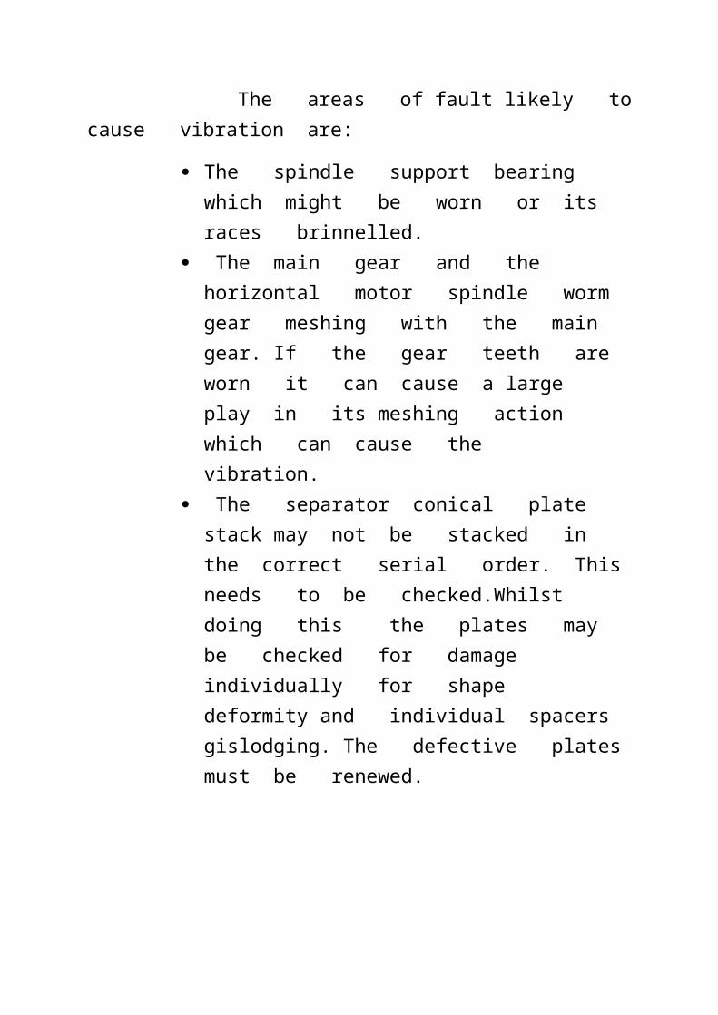
The areas of fault likely to cause vibration are:
The spindle support bearing which might be worn or its races brinnelled.
The main gear and the horizontal motor spindle worm gear meshing with the main

gear. If the gear teeth are worn it can cause a large play in its meshing action which can cause the vibration.
The separator conical plate stack may not be stacked in the correct serial order. This needs to be checked.Whilst doing this the plates may be checked for damage individually for shape deformity and individual spacers gislodging. The defective plates must be renewed.
Q5. What is Rocking test of Deck Crane? Explain the procedure of rocking test. Tabulate and indicate fault finding procedure. What is the action taken if deviation is out of limit?
Answer:- The rocking test of the deck crane is donr to measure the wear down of the pedestal slewing bearing of the cage along with jib.

The slewing bearing rocking test should be done periodically for the bearing wear tracking and early failure detection.The measurement could be done from the inside and outside of pedestal. Follow the maker's recommendations and conduct the test at the same check points as during the initial test during commissioning in order all subsequent measurements have the same reference 0. The measurement should be done as follows:1. Two checkpoints should be chosen on the pedestal at
the circumference close to the revolving side shell of the crane (see the drawing above) normally at the FWD and AFT of pedestal. Some makers recommend to carry out measurements at four points: FWD, AFT, PORT and STBD of pedestal. Measurement points normally marked at the pedestal.
1. Note a reference metal bar welded to pedestal at measurement point

2. Measurement should be done by depth meter at four directions of boom: FWD, AFT, PORT and STBD. At each boom direction two or four readings must be taken (see item 1 above), check maker's recommendations for details. Record obtained figures on the log sheet. Result of periodic measurement record should be compared with the max. allowable deviation provided by the manufacturer.
1. Some rocking test procedures require to use a dial gauge instead of depth meter.
In this case dial gauge set to 0 after installing at the measurement point and readings taken at four boom positions: FWD, AFT, PORT and STBD. Same procedure repeated for all measurement points as it was done during initial the rocking test

If the deviation exceeds the limit the bearing races and assembly has to be renewed.
Q6. With the aid of a simple sketch, explain the “trouble spots” in a basic air-conditioning unit with reference to your sketch, explain the following: -i. How the problem of increase in humidity on cooled air is overcome; ii. How discomfort caused by the excessive drying effect of heated air is overcome.
Answer:-Repeat question.
Q7. A. State the circumstances owing to which it may be necessary to renew a cylinder liner; B. Explain how the liner is removed; C. Explain how a new liner is fitted; D. State the important checks to be made after fitting.
Answer:- Repeat question.
Q8. Write short notes on following:A. Magnetic Particle Inspection (MPI) B. Ultrasonic Testing (UT) C. Radiographic Testing (RT)
Answer:- Magnetic particle inspection:- Magnetic particle Inspection (MPI) is a non-destructive testing (NDT) process for detecting surface and shallow subsurface discontinuities in ferromagnetic materials such as iron, nickel, cobalt, and some of their alloys. The process puts a magnetic field into the part. The piece can be magnetized by direct or indirect magnetization. Direct magnetization occurs when the electric current is passed through the test object and a magnetic field is formed in the material. Indirect magnetization occurs when no electric current is passed through the test object, but a magnetic field is applied from an outside source. The magnetic lines of force are perpendicular to the direction of the electric current, which may be either alternating current (AC) or some form of direct current (DC) (rectified AC).
The presence of a surface or subsurface discontinuity in the material allows the magnetic fluxto leak, since air cannot support as much magnetic field per unit volume as metals.To identify a leak, ferrous particles, either dry or in a wet suspension, are applied to a part. These are attracted to an area of flux leakage and form what is known as an indication, which is evaluated to determine its nature, cause, and course of action, if any.
Ultra sonic testing(UT):- High-speed Ultrasonic (UT) Systems enable a full volumetric examination of materials and are designed to detect surface, subsurface, internal and dimensional flaws.
Ultrasonic inspection can be used to detect surface flaws, such as cracks, seams, and internal flaws such as voids or inclusions of foreign material. It’s also used to measure wall thickness in tubes and diameters of bars.
An ultrasonic wave is a mechanical vibration or pressure wave similar to audible sound, but with a much higher vibration frequency. For NDT purposes, the range is usually from 1MHz to 30MHz.
Depending on the test requirements, these waves can be highly directional and focused on a small spot or thin line, or limited to a very short duration.
Two methods of UT are used for flaw detection – Shear and Compression Wave.
Shear method uses an angled beam that is usually 45˚. This enables surface and subsurface testing. Surface cracks, seams and near surface inclusions can be detected with the shear method. Shear method can overlap the normal incidence method

inspection and result in a 100% volumetric test of the bar.
Compression is also know as normal incidence. This is the primary internal inspection for bar testing. The transducer is set to exactly enter the bar surface perpendicular to the surface. This inspection method is limited to the entire bar volume except approximately a 3mm thick outer shell.
Radiographic testing.(RT):- Radiographic Testing (RT) is a nondestructive examination (NDE) technique that involves the use of either x-rays or gamma rays to view the internal structure of a component. In the petrochemical industry, RT is often used to inspect machinery, such as pressure vessels and valves, to detect for flaws. RT is also used to inspect weld repairs.
Compared to other NDE techniques, radiography has several advantages. It is highly reproducible, can be used on a variety of materials, and the data gathered can be stored for later analysis. Radiography is an effective tool that requires very little surface preparation. Moreover, many radiographic systems are portable, which allows for use in the field and at elevated positions.
Types of Radiography
There are numerous types of RT techniques including conventional radiography and multiple forms digital radiographic testing. Each works slightly differently and has its own set of advantages and disadvantages.
Conventional RadiographyConventional radiography uses a sensitive film which reacts to the emitted radiation to capture an image of the part being

tested. This image can then be examined for evidence of damage or flaws. The biggest limitation to this technique is that films can only be used once and they take a long time to process and interpret.
Digital RadiographyUnlike conventional radiography, digital radiography doesn’t require film. Instead, it uses a digital detector to display radiographic images on a computer screen almost instantaneously. It allows for a much shorter exposure time so that the images can be interpreted more quickly. Furthermore, the digital images are much higher quality when compared to conventional radiographic images. With the ability to capture highly quality images, the technology can be utilized to identify flaws in a material, foreign objects in a system, examine weld repairs, and inspect for corrosion under insulation.
The four most commonly utilized digital radiography techniques in the oil & gas and chemical processing industries are computed radiography, direct radiography, real-time radiography, and computed tomography.
Read More

Q9. Describe the procedure for overhauling a boiler safety valve and explain using sketches where necessary those parts, which require close attention. Also describe the procedure setting of boiler safety valves.


![[3] involuteΣ Worm Gear Design System · [3] involuteΣ Worm Gear Design System Fig. 3.1 involuteΣ Worm Gear Design System 3.1 Introduction The involuteΣ Worm Gear Design System](https://img.dokumen.tips/doc/110x75/5eadff0184c9a55408434a64/3-involute-worm-gear-design-3-involute-worm-gear-design-system-fig-31.jpg)