Embed Size (px)
Citation preview

THE MclNTOSH MC 2300 SOLID STATE STEREO POWER AMPLIFIER
Price $1.25


The Mclntosh MC 2300 is a high quality, ex-tremely high power, solid state stereo ampli-fier. Because of the high power available it isnecessary to emphasize some prudent andsafe operating conditions.
1. Never connect or disconnect inputs oroutputs while the amplifier is turned on.Loudspeakers can be damaged or de-stroyed by the high power available fromthe instrument.
2. Never operate the amplifier with the powercord plugged into an auxiliary AC poweroutlet on source equipment. The amplifierdraws near 14 amperes at full power anddamage to the source equipment canoccur.
3. Do not operate the instrument pluggedinto an ordinary extension cord. Heavyduty extension cords (14 ga. or heavier)have adequate wire size and will not over-heat.
4. Be cautious when lifting the instrument.It weighs 128 pounds. Make certain thatwhat it is placed on can support theweight.

Your MC 2300 Stereo Power Amplifierwill give you many years of pleasantand satisfactory performance. Ifyou have any questions concerningthe operation or maintenance ofthis instrument, please contact:
CUSTOMER SERVICEMclntosh Laboratory Inc.2 Chambers StreetBinghamton, New York 13903Phone: 607-723-3512
Take Advantage of 3 yearsof FREE Factory Service . . .Fill in the Application NOW.
CONTENTSGUARANTEE.... 1
INSTALLATION.... 3
HOW TO CONNECT....4,5Stereophonic.... 6Monophonic.... 7
FRONT PANEL INFORMATION.... 8
PERFORMANCE LIMITS.... 9
TYPICAL PERFORMANCE CHARTS.. . .10
TECHNICAL DESCRIPTION....11
BLOCK DIAGRAM.. . .16
An application for a FREE THREE YEAR FACTORYSERVICE CONTRACT is included with this manual.The terms of the contract are:
For Three Years from date of purchase —1. Mclntosh will provide all parts, materials and
labor needed to return the measured performanceof the instrument to the original performancelimits free of any charge. The SERVICE CON-TRACT does not cover any shipping costs to andfrom the authorized service agency or the factory.
2. Any Mclntosh authorized service agency will re-pair all Mclntosh instruments at normal servicerates. To receive the free service under the termsof the SERVICE CONTRACT, the SERVICE CON-TRACT CERTIFICATE must accompany the instru-ment when taken to the service agency.
3. Always have service done by a Mclntosh author-ized service agency. If the instrument is modifiedor damaged, as a result of unauthorized repair theSERVICE CONTRACT will be cancelled. Damageby improper use or mishandling is not covered bythe SERVICE CONTRACT.
or one of its authorized agencies wilt repair thedefect at no cost to the purchaser. This guaranteedoes not extend to components damaged by im-proper use nor does it extend to transportation toand from the factory or service agency.
4. The SERVICE CONTRACT is issued to you as theoriginal purchaser. To protect you from misrepre-sentation this contract cannot be transferred to asecond owner.
5. The SERVICE CONTRACT is given to purchaserswho live In the 50 United States or Canada only.
6. For your protection Mclntosh selects Its dealerscarefully. Only one dealer in ten qualifies for aMclntosh franchise. To receive the SERVICECONTRACT your purchase must be made from aMclntosh franchised dealer.
7. Your completely filled In application for a SERV-ICE CONTRACT must be postmarked within 30days of the date of purchase of the instrument.
8. To receive the SERVICE CONTRACT all informa-tion on the application must be filled in. TheSERVICE CONTRACT will be issued when thecompletely filled in application is received atMclntosh Laboratory Incorporated in Binghamton,New York. If the application is not received atMclntosh Laboratory, only the service offeredunder the 90-day guarantee will apply.
Copyright © 1971 by Mclntosh Laboratory, Inc.
Mclntosh Laboratory Incorporated guarantees thisInstrument to be capable of performance as adver-tised. We also guarantee the mechanical and elec-trical workmanship and components to be free ofdefects for a period of 90 days from date of pur-chase. If such defects occur, Mclntosh Laboratory
GUARANTEE
2

InstallationInstallation of the MC 2300 requires careful thought
about three important factors. They are the electricalpower to operate the unit, the weight and the heatgenerated when the MC 2300 is operating.
The MC 2300 draws 1400 watts or about 14 am-peres when operated at full power. Do not use ordi-nary extension cords of any type. Heavy duty exten-sion cords (14 ga. or heavier) have adequate wiresize and will not overheat. Plug the AC power corddirectly into a wall outlet. Make certain that the ACpower outlet has at least 15 amperes capacity withnothing else using the circuit. Do not plug the MC2300 into an auxiliary AC power outlet on a pre-amplifier or other source equipment. If remote poweroperation is required, an external relay arrangementmust be made.
Weight of the instrument is 128 pounds. Makecertain that the shelf on which it is to be mountedcan support that weight. If it is to be verticallymounted, be certain the structure is capable of sup-porting the MC 2300.
Adequate ventilation extends the trouble-free lifeof electronic instruments. It is generally found thateach 10° centigrade (18° F) rise in temperature re-duces the life of electrical insulation by one half.Adequate ventilation is an inexpensive and effectivemeans of preventing insulation breakdown that re-sults from unnecessarily high operating tempera-tures. The direct benefit of adequate ventilation islonger, trouble-free life. Provide a source for inputair and an outlet for the heated air. The heat gener-ated in the operation of the MC 2300 is exhaustedfrom the unit by two low noise, long life fans.
Cooling input air is drawn into the MC 2300through the ventilation holes on the sides of theMC 2300. The air passes over the tranformers, outputheat sinks and transistors; and, is blown out the backof the instrument by the two fans. It is recommendedthat at least 2 inches of clear space be provided oneach side.
To permit the fans to operate best, provide at least5 inches of space at the rear of the instrument. Asource for input air and a means to exhaust theheated air is necessary so that the heated air doesnot recirculate through the MC 2300.
To install the unit in a cabinet the aluminum siderails with the feet attached must be removed. The
rails are attached to the front panel by 8 #10-32machine screws and to each side by 4 small clips.Remove both the front panel screws and the fourclips from each side for cabinet mounting. The open-ing to fit the unit is 17¼ by 10¼ inches.
RACK INSTALLATION
The MC 2300 may be mounted in a standard 19"rack by removing the aluminum side rails. If a stand-ard rack is used, the screws that held the aluminumrails to the front panel are used to attach the MC2300 to the rack. When rack mounted, the MC 2300requires 10½ inches of panel space. Allow twoinches in front of the panel for the knobs. A depth of17 inches plus ventilation space is required.
The MC 2300 can be slide mounted in a rack.Tapped well nuts and internal structure bracing hasbeen added to both sides of the MC 2300 for usewith the Model CTS-116 side mounted slide assem-blies manufactured by Chassis-Trak Inc., Indian-apolis, Indiana.
3

How to ConnectINPUT
Stereo or twin amplifier operation:
Use shielded cables to connect the signal from thepreamplifier or signal source to the power amplifier.All connection are made on the back panel of theMC 2300.
For stereo operation the LEFT OUTPUT of the pre-amplifier should be connected to the LEFT INPUT ofthe power amplifier. The RIGHT OUTPUT of the pre-amplifier should be connected to the RIGHT/MONOinput of the power amplifier. In stereo or twin ampli-fier operation the MODE SWITCH must be in thestereo position.
For twin amplifier operation a separate signalsource can be connected to each input.
To minimize the possibility of hum the shieldedleads shall be run parallel or loosely twisted to-gether. Locate the cables away from AC power cords.
Monophonic or Single Channel operation:
A shielded cable from the signal source is con-nected to the RIGHT/MONO input of the MC 2300.The MODE SWITCH on the back panel of the ampli-fier must be placed in the MONO position. In theMONO position the output of the right channel inputamplifier is fed to both left and right power amplifiers.The LEFT INPUT is disconnected. Only the signal fedinto the RIGHT/MONO input will be amplified. Shouldthe MODE SWITCH be left in the STEREO positionand the output transformers be strapped to a mono-phonic load, one channel will attempt to drive theother and cause high circulating currents and over-heating. Be certain that the MC 2300 is never oper-ated in the stereo mode with the outputs connectedfor monophonic operation.
OUTPUT
Stereo or twin amplifier operation:
To connect the left speaker first check the imped-ance of the speaker which is usually identified onthe speaker itself or in the owner's manual. Connectone lead from the common terminal of the speaker tothe LEFT CHANNEL OUTPUT terminal strip screwCOMmon. Connect the other terminal of the speakerto the screw with the number corresponding to thespeaker impedance on the LEFT CHANNEL OUTPUTterminal strip. The right channel speaker is con-nected in the same manner on the RIGHT CHANNELOUTPUT terminal strip. For stereo or twin channel
operation it is not necessary to use the same impe-dance loudspeaker on each output. Connect eachchannel for the impedance desired.
When multiple speakers are to be connected toeither or both outputs, the combined load impedancemust be calculated and the load connected to theappropriate impedance tap. The following table willaid in selecting the correct impedance match.
Load Loadimpedance Connect impedance Connect
in ohms
0.4 to 0.90.9 to 1.81.8 to 3.6
to
0.512
in ohms
3.6 to 7.27.2 to 14.4
14.4 to 28
to
48
16
If a load impedance is used that is lower than theoutput impedance tap, then reduced power and pos-sible distortion will result. If a load impedance is usedthat is higher than the output impedance tap, thenneither the signal nor the amplifier will be harmed butthe voltage available is limited to that stated at thattap.
For constant voltage line operation:
25 volts Connect to 2 ohms70 volts Connect to 16 ohms
Make all speaker connections at the amplifier only.For multiple speaker operation, parallel the leadsfrom the speakers to the amplifier.
Because of the high power available from the MC2300, be sure to use large diameter speaker leads. Inall cases, the leads to and from the speaker shouldbe twin conductor or twisted together.
Use lamp cord, bell wire, or wire with similar typeof insulation to connect the speakers to the ampli-fier. For the normally short distances of under 20 feetbetween the amplifier and speaker #18 wire or largercan be used. For distances over 20 feet between theamplifier and speaker use larger diameter wire. Se-lect the correct size wire for the wire distance fromthe chart.
It is recommended that the DC resistance of thespeaker leads not be over 5% of the load impedance.Up to 10% can be tolerated. Resistance of the leadsshould be computed for the length of wire both toand from the speaker or speakers.
4

Monophonic or Single Channel operation:
When the MC 2300 is used as a monophonic orsingle channel power amplifier the two channels arecombined to produce output up to 600 watts. Theoutput must be tied together at the appropriate loadimpedance tap. In connecting a load to the MC 2300for single channel operation connect the commonside of the load to the LEFT CHANNEL OUTPUT ter-minal marked COM., the other lead as below.
For monophonic constant voltage line operation:
If the speaker The hot sideor load of the line Is
Impedance Is: connected to:
Connect a jumperwire between:
0.25 ohms0.5 ohms
2 ohms4 ohms8 ohms
Left 0.5Left 1
Left 4Left 8Left 16
Left 0.5 and Right 0.5Left 1 and Right 1
Left 4Left 8Left 16
and Right 4and Right 8and Right 16
If the load impedance is between any of the abovefigures seclect the best impedance match from thischart:
Load Impedancein ohms
0.4 to 0.90.9 to 1.81.8 to 3.6
Connect to
0.512
Load Impedancein ohms
3.6 to 7.27.2 to 14.4
14.4 to 28
Connect to
48
16
If the outputvoltage is:
25 volts70 volts
The hot sideof the load isconnected to:
Left 2Left 16
Connect a jumperwire between
Left 2 and Right 2Left 16 and Right 16
Make all speaker connections at the amplifier only.For multiple speaker operation, parallel the leadsfrom the speakers to the amplifier.
Should the MODE SWITCH be left in the STEREOposition and the output transformers be strapped toa monophonic load, one channel will attempt to drivethe other and cause circulating currents and over-heating. Be certain that the MC 2300 is never oper-ated in the stereo mode with the outputs connectedfor monophonic operations.
AC POWER
The MC 2300 is designed to operate on 117 to 130volts 50/60 Hz. Do not use ordinary extension cordsof any type. Heavy duty extension cords (14 ga. orheavier) have adequate wire size and will not over-heat. Plug the the AC power cord directly into a walloutlet. Make certain that the AC power outlet has atleast 15 ampere capacity with nothing else using thecircuit. Do not plug the MC 2300 into an auxiliary ACpower outlet on a preamplifier or other source equip-ment unless it is known there is adequate currentcapacity. If remote power operation is required, anexternal relay arrangement must be made.
WIRE GAUGE 22 20 18 16 14
12
10
8
6
50 75 100 150 200
LENGTH IN FEET OF TWO-CONDUCTOR SPEAKER WIRE
250 3000
5

STEREOPHONIC CONNECTIONS
PROGRAM SOURCE
TO 120 VAC
DO NOT CONNECT LINECORD INTO PREAMPLIFIERAC OUTLETS.IF REMOTE POWERCONTROL IS NEEDEDUSE AN EXTERNALRELAY.
6LEFT SPEAKER ML 4 C RIGHT SPEAKER ML 4 C
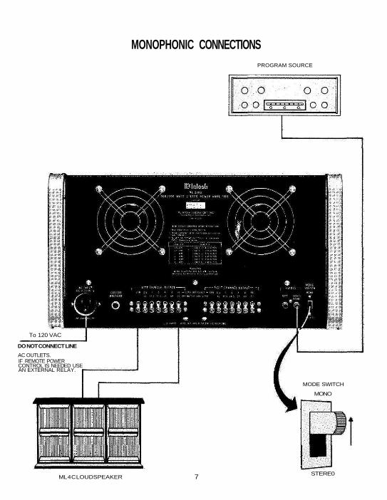
MONOPHONIC CONNECTIONSPROGRAM SOURCE
To 120 VAC
DO NOT CONNECT LINE
AC OUTLETS.IF REMOTE POWERCONTROL tS NEEDED USEAN EXTERNAL RELAY.
MODE SWITCH
MONO
7 STERE0ML 4 C LOUDSPEAKER

Front Panel InformationLEFT GAIN
The left gain control is used to control gain or volumeof the left channel. Clockwise rotation increases gain.
RIGHT/MONO GAIN
In stereo the RIGHT/MONO GAIN control deter-mines the gain or volume of the right channel only.Clockwise rotation increases gain. If the MC 2300 isconnected as a monophonic or single channel ampli-fier, the gain or volume is controlled by the RIGHT/MONO GAIN control.
Both controls have a standard volume controltaper. The numerals around the controls are providedfor reference. They do not represent relative outputversus rotation.
METER RANGE
The meter switch has four positions. The first posi-tion is OFF. With switch in the OFF position there isno indication on the meters.
0: In this position of the meter range switch, theamplifier will deliver 300 watts when the meter in-dicates + 3 dB, with meter indication of "0," theamplifier delivers 150 watts, with a meter indicationof —3 dB, the amplifier delivers 75 watts.
—10: In this position of the meter range switch,the amplifier will deliver 15 watts output when themeter indicates "0."
—20: In this position of the meter range switch,the amplifier will deliver 1.5 watt when the meterindicates "0."
Two meters monitor and indicate the output powerin each channel. The meters indicate peak power out-put of the monitored channel. To assure more accu-rate indications of peak power, Mclntosh's peak lock-ing circuits stretch the peak reading of rapid chang-ing information long enough to give adequate visualperception. Ordinary meters lack the capability of in-dicating the short interval of power in a sound wave.The mass of the meter movement is too great to re-spond to the nearly instantaneous changes in musicprogram material. Mclntosh has developed circuitsthat permit the meters of the MC 2300 to respond tothe short interval power in a sound wave to an accu-racy of 98%.
Monitoring of the output power is done at the pri-mary or input of the autoformer resulting in truepower readings regardless of output impedanceselected.
The graph represents the relationship between themeter reading and power output for all three meterranges:
POWER
The power switch turns the MC 2300 on or off. Ifyou wish to control the on/off operation of the ampli-fier remotely, use a control relay in series with thepower line and leave the power switch in the ONposition. Do not plug the MC 2300 into any of theauxiliary AC power outlets of the preamplifier orother associated equipment unless that equipmenthas power capacity for handling 1400 watts (14 am-peres).
8

Performance LimitsPERFORMANCE GUARANTEE
Performance Limits are the maximum deviationfrom perfection permitted for a Mclntosh instrument.We promise you that the MC 2300 you buy must becapable of performance at or exceeding these limitsor you qet your money back. Mclntosh is the only
POWER OUTPUTSTEREO: 300 watts continuous, both channels op-erating; which is:
12.2 volts RMS across 0.5 ohm17.3 volts RMS across 1 ohm24.5 volts RMS across 2 ohms34.6 volts RMS across 4 ohms49.0 volts RMS across 8 ohms69.3 volts RMS across 16 ohms
MONO: 600 watts continuous; which is:12.2 volts RMS across 0.25 ohm17.3 volts RMS across 0.5 ohm24.5 volts RMS across 1 ohm36.6 volts RMS across 2 ohms49.0 volts RMS across 4 ohms69.3 volts RMS across 8 ohms
HARMONIC DISTORTIONStereo:
Less than 0.25% at 300 watts output from 20 Hzto 20,000 Hz both channels operating. Typical per-formance is less than 0.1% at rated power. Distor-tion decreases as output power is reduced.
Mono:
Less than 0.25% at 600 watts output from 20 Hz to20,000 Hz. Typical performance is less than 0.1%at rated power. Distortion decreases as outputpower is reduced.
INTERMODULATION DISTORTIONStereo:
Less than 0.25% if instantaneous peak power is600 watts or less per channel with both channelsoperating for any combination of frequencies 20Hz to 20,000 Hz.
Mono:
Less than 0.25% if instantaneous peak power is1200 watts or less for any combination of fre-quencies 20 Hz to 20,000 Hz.
FREQUENCY RANGEStereo:
20 Hz to 20,000 Hz, +0 - 0.5 dB at rated power;1, 4, 8 or 16 ohms
20 Hz to 20,000 Hz, +0-1.0 dB at rated power;0.5 and 2 ohms
12 Hz to 35,000 Hz, +0 - 1.5 dB at one-half ratedpower
Mono:
20 Hz to 20,000 Hz, +0 - 0.5 dB at rated power;0.5, 2, 4 or 8 ohms
20 Hz to 20,000 Hz, +0-1.0 dB at rated power;0.25, and 1.0 ohms
12 Hz to 35,000 Hz, +0 - 1.5 dB at one-half ratedpower
NOISE AND HUM90 dB below rated output
OUTPUT POWER MONITOR METERMeter is calibrated to read +3 db when ampli-
fier produces 300 RMS watts or 600 peak watts.Meter range switch is provided to increase metersensitivity by 10 dB or 20 dB.
Meter features special circuit to respond to peakvalues of complex input signal. Calibration accuracyat 0 dB is ±2% at all frequencies; meter range accu-racy is ±5%.
OUTPUT IMPEDANCEStereo: 0.5, 1, 2, 4, 8, and 16 ohms
Mono: 0.25, 0.5, 1, 2, 4, and 8 ohms
OUTPUT VOLTAGES25 volts, stereo and mono; 70 volts, stereo and
mono
DAMPING FACTOR27 at 0.5 ohm output, 50 at 1 ohm output, 29 at 2
ohm output, 21 at 4 ohm output, 14 at 8 ohm output.
INPUT IMPEDANCE200,000 ohms
INPUT SENSITIVITY0.5 volts input required to produce rated output.
Level control provided for input voltages up to 30volts.
POWER REQUIREMENTS120 volts, 50/60 Hz, 160 watts at zero signal out-
put. 1400 watts at rated output.
SEMICONDUCTOR COMPLEMENT46 Silicon transistors, 22 Silicon rectifiers and
diodes
MECHANICAL INFORMATION
SIZE: Front pane! measures 19 inches wide (48.26cm) by 10½ inches high (26.67 cm). Chassis meas-ures 17 inches wide (43.18 cm) by 10 inches high(25.4 cm) by 17 inches deep (43.18 cm), includingconnectors. Clearance in front of mounting panel in-cluding knobs 2 inches (5.08 cm)
FINISH: Front panel is anodized gold and black.Chassis is black baked enamel.
MOUNTING: Standard 19" (48.26 cm )rack mounting.
WEIGHT: 128 pounds (58.06 kg) net, 143 pounds(64.86 kg) in shipping carton.
SPECIAL FEATURES: The amplifier is completelystable when connected to any loudspeaker systemand to any reactive loads. The MC 2300 has specialcircuits to prevent damage by short circuit or opencircuit of the output loads, or by any amount of out-put impedance mis-match.
Thermal cutouts are mounted on the output tran-sistor heat sinks to provide protection in the event ofinadequate ventilation.
9

HARMONIC DISTORTION vs. POWER OUTPUT
TypicalPerformanceCharts
.1 1POWER OUTPUT IN EQUIVALENT AVERAGE WATTS
10 100 1000
10
.7
.6
.5
.4
.3
.2
.1
0
INTERMODULATION DISTORTION
10 100 1000FREQUENCY HERTZ
10K 100 K
400
360
320
280
240
200
160
120
80
40
0
POWER BANDWIDTH
.1 1POWER OUTPUT IN AVERAGE WATTS
10 100 1K
.5
.4
.3
.2
.1
0

Technical DescriptionEach channel of the MC 2300 can be divided into
five different sections. These sections are (1) inputamplifier, (2) power amplifier circuit, (3) limiter cir-cuit, (4) meter circuit and (5) power supplies.
INPUT AMPLIFIER
The MC 2300 will deliver rated output from an in-put signal of 0.5 volts. The input control reduces theamount of signal into the input amplifier as the set-ting is reduced. By the correct setting of the controlinput signals on the order of 30 volts can be appliedto the input of the MC 2300 without overdriving theinput. At the input amplifier two NPN transistors, Q2and Q4, are connected in a differential amplifier ar-rangement. The two inputs to the differential amplifierare the input signal and the feedback signal from theoutput of the input amplifier. The use of a differentialamplifier provides the most efficient use of largeramounts of negative feedback to maintain low noiseand distortion. The combined output of the differen-tial amplifier feeds a common emitter voltage ampli-fier Q6. The output of the Q6 is coupled via a largevalue capacitor to the power circuit and to the feed-back input of the differential amplifier. A large valuecapacitor is used to assure good low frequency re-production and to assure that no DC is coupled tothe power amplifier circuits. From the collector ofQ6 the resistors R20 and R18 form a dividing networkwhich determines the amount of negative feedbackfed to the differential amplifier. The path providesboth AC and DC feedback. A small trimming capaci-tor parallels R20 to increase the amount of feedback
at frequencies above 50,000 Hz. This increased feed-back reduces the noise level of the input sectionwhere the signal to noise level is more critical, it alsorolls off the frequency response above 50,000 Hz.Resistors R9 and R10 with C5 C6 form a filter chainto filter the ± 21 volts used to supply the input am-plifier. Left and right channels operate identically.The output of the left and right input amplifiers is fedto the mono/stereo switch.
OPERATION OF MONO/STEREO SWITCH
If the MODE switch is in the STEREO positioneach input amplifier is directly connected to its re-spective power amplifier. In the MONO position theoutput of the right channel input amplifier is fed toboth left and right power amplifiers, the LEFT INPUTis disconnected. For stereo or twin channel opera-tion the MC 2300 has two independent amplifyingsections. Consequently, each amplifier output can beloaded with any desired impedance load. For MONOoperation the two power amplifier output sectionsare connected together for parallel operation. Theoutput load therefore must be connected to the out-put of each channel strapped together in parallel.Should the MODE switch be left in the STEREOposition and the output transformers be strapped toa mono load, one channel will attempt to drive theother and cause high circulating currents and over-heating. Be certain that the MC 2300 is never oper-ated in the stereo mode with the outputs strappedin parallel.
POWER AMPLIFIER
At the right input channel power amplifier input,two PNP transistors (Q102 and Q104) are connectedin a differential amplifier configuration. As in the
11

12

input amplifier the two signals to the differentialamplifier are the normal power amplifier input sig-nal and the negative feedback signal from the poweramplifier output. The combined output of the differ-ential amplifier feeds transistor Q106 which is acommon emitter Class A linear voltage amplifier. Theoutput of Q106 is directly coupled to the bases oftransistors Q112 and Q118 which are NPN and PNPcomplementary medium power driver transistors. Thedriver stages furnish the current required to thebases of the output transistors Q116 thru Q138. Out-put transistors Q116, 120, and 124, 128, 132, 136 con-
trol the positive portion of the output signal whiletransistors Q118, 122, 126, 130, 134, 138 control thenegative half of the output signal. These 12 outputtransistors work together forming a series push-pulloutput capable of delivering extremely high currents.The output transistors are mounted on oversizedblack anodized heat sinks. Two long life quiet run-ning fans draw air over the heat sinks and out therear of the unit. With all covers in place the MC 2300will run relatively cool even under full load condi-tions. Resistor R112 completes the DC negative feed-back path to the differential input while the resistorsR112 and R106 form a voltage divider network forthe AC negative feedback.
A high value resistor, R118, in series with a highvoltage power supply acts as a current source for thedriver transistors Q112 and Q114. The dual diodeD104 and resistor R27 set the standing current for allof the output transistors to achieve Class B operation.Driver transistor Q112 is physically mounted atop thedual junction diode D104 causing the junction volt-age drop to decrease as the diode is heated. Thischange in voltage causes the standing current to re-main constant regardless of the operating tempera-tures.
13

LIMITER CIRCUIT
In the power amplifier circuit the amount of signaloutput has a linear relationship with the input signal.In the event of a short circuit or severe impedancemismatch the limiter circuit will protect the outputtransistors against failure. The Mclntosh patentedSentry Monitoring circuit constantly monitors the out-put signal and instantly reacts to prevent overload tothe output transistors. At signal levels up to rated out-put the limiter circuit is a high impedance circuit inall modes and has no effect upon the output signal.If the power output exceeds the design limits thelimiter circuit becomes low impedance and reducesthe signal to the output transistors.
Both positive and negative halves of the output aremonitored independently and the circuit operationis similar for both halves. The amount of current flow-ing through an output transistor is monitored by sens-ing the voltage measured across the emitter (posi-tive) or collector (negative) resistor relative to theoutput buss. This voltage is applied to the base of thelimiter transistor Q107 (positive) and/or Q109 (nega-tive) via the voltage dividing network R121, 129 (posi-tive) and/or R123, R131 (negative). When the currentflowing in the output attempts to exceed the designlimits then the voltage at the base of the limiter tran-sistors causes those transistors to conduct making aportion of the signal to the base of the driver tran-sistors Q111 (positive) and Q113 (negative) to bedrained off.
METER CIRCUIT
Ordinary meters lack the capability of indicatingthe short interval of power in a sound wave. The massof the meter movement is too great to respond to the
nearly instantaneous changes in music program ma-terial. Mclntosh has developed circuits that permitthe meters of the MC 2300 to respond to the shortinterval power in a sound wave to an accuracy of98%.
Monitoring of the output power is done at the pri-mary or input of the autoformer. Sampling the outputpower in this portion of the circuit gives true powerreadings regardless of output impedance selected.To be able to read power peaks that are sustainedfor such extremely short durations, Mclntosh engi-neers developed circuits that accelerated the up-swing of the meter and caused the needle to be heldat the peak reading long enough for the human eyeto perceive the indication of the needle. The Mc-lntosh meter circuit is a dynamic peak locking metercircuit that does both things. (Patented)
Diode D203 and resistor R217 tied to the negativesupply place a bias on the emitter of transitor Q201to hold the transistor just at the threshold of conduc-tion. Diode D201 passes only the positive portions ofthe input signal to the base of Q201 charging the ca-pacitor C201. Since the transistor Q201 is on theedge of conduction the slightest positive swing of in-put signal causes conduction to begin. The largestcapacitor C203 in the emitter circuit will appear as adirect short at first to the negative supply thereby ac-celerating the needle of the meter upscale. At thepeak of the signal the needle will stop its upswing.When the meter needle reaches peak and the inputsignal starts a downswing, the capacitor C201 startsto lose its charge by the RC time constant of C201,R209. For that amount of time a positive charge issupplied to the base of Q201 causing it to conduct fora longer length of time. The RC combination R215,
14

C203 act as a meter upswing accelerator while theRC combination R209, C201 act as a pulse or timestretching aid. Variable resistor R213 is used to ad-just the meter to read exactly " + 3" at 300 wattsRMS. All components of the meter circuit have beenselected and designed to have maximum flat re-sponse at the frequency extremes. A reading of agiven power is correct regardless of the frequencyof the signal. The MC 2300 contains two independentmeters and meter circuits. Both meter circuits oper-ate the same and are completely independent exceptfor meter range setting. The meter range switch doesnot alter the sensitivity of the meter circuit but attenu-ates, by the correct ratio, the amount of input signalto the meter circuit.
POWER SUPPLIES
To deliver rated power at frequency extremes, de-sign of a power amplifier supply must have goodregulation and ample reserve. At lower frequenciesthe power supply capacitors must be of sufficientsize to deliver full voltage, cycle after cycle, with noincrease in ripple. At higher frequencies power tran-sistors require more power. The power supply mustbe able to furnish the additional power without sacri-ficing regulation or overheating. In all cases the
power furnished to one channel should have no effectupon the performance of second channel. Any effectwould cause cross talk and poor channel separation.In stereo use a stereo power amplifier must act astwo separate amplifiers whether their power signalsare common or separate. This design goal is fullyachieved in the MC 2300.
In the Mclntosh MC 2300 two high current suppliesare used. Each high current supply furnishes thepositive and negative forty volts required in the poweroutput circuits. The four 39,000 microfarad capaci-tors store ample power (over 120 joules) for fre-quencies in the low range. The power transformerhas been designed to run relatively cool at full poweroutput. Bridge rectifiers D301 and D302 are used inboth high current supplies for most efficient conver-sion of power.
A high voltage lower current supply is designed tofurnish power to the lower level and driver circuits.Full wave recification and considerable filtering as-sure clean signal amplification with no added hum ornoise.
A resettable circuit breaker in the primary of thepower transformer and two heat sensing switchesS302, S303 protect the amplifier against overloadand/or overheat.
15

Block Diagram
16


MCINTOSH LABORATORY INC.2 CHAMBERS ST., BINGHAMTON, N. Y. 13903
607-723-3512
Design subject to change without notice.Printed in U.S.A.
038-662


![[XLS] - Mar15/District Reasi new proforma... · Web view2035 2300 2036 2300 2037 2300 2038 2300 2039 2300 2040 2300 2041 2300 2042 2300 2043 2300 2044 2300 2045 2300 2046 2300 2047](https://img.dokumen.tips/doc/110x75/5aa68dbc7f8b9a517d8ea409/xls-mar15district-reasi-new-proformaweb-view2035-2300-2036-2300-2037-2300.jpg)