Embed Size (px)
Citation preview
The MAC Sublayer
The Medium Access Control (MAC) sublayer is the bottom half of the Datalink layer. The upper half is commonly called the Logical Link Control (LLC) sublayer.
Primary function Arbitrate access to a shared transmission medium. The MAC sublayer is NULL for point to point channels.
Motivation for the use of a shared channel:
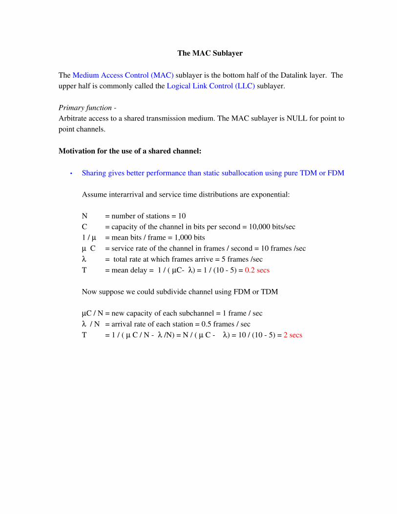
• Sharing gives better performance than static suballocation using pure TDM or FDM
Assume interarrival and service time distributions are exponential:
N = number of stations = 10C = capacity of the channel in bits per second = 10,000 bits/sec1 / = mean bits / frame = 1,000 bits C = service rate of the channel in frames / second = 10 frames /sec = total rate at which frames arrive = 5 frames /secT = mean delay = 1 / ( C ) = 1 / (10 5) = 0.2 secs
Now suppose we could subdivide channel using FDM or TDM
C / N = new capacity of each subchannel = 1 frame / sec / N = arrival rate of each station = 0.5 frames / sec T = 1 / ( C / N /N) = N / ( C ) = 10 / (10 5) = 2 secs
• Sharing is cheaper than replication (dedicated paths between endpt pairs)
Nevertheless, replication is becoming common in wired networks
LANs are now commonly starwired with a central switchThe switch supports concurrent transfers between different host pairsThe switch contains some output buffering for common targets.
• Sharing instead of replication may be the only viable option
For wireless nets its not possible to replicate space!For cable nets replication would defeat the primary advantage of cable no need to star wire the world as in the telphone system.
2
Model parameters for shared medium MAC analysis
Station model:N independent stations. Each generates frames at rate
Channel modelA single channel is used by all stationsNo hardware based priority assignment (as there is on a computer system bus)Two frames whose transmissions overlap cause a collision that destroys both.
Timing modelContinuous time: frames may be transmitted at any time.Slotted time: frames may be transmitted only at distinct clock ticks
Channel sense modelCarrier sense: stations can determine if channel is busy before sendingNo carrier sense: not possible to determine if channel is in use
Collision model:Collision detection: stations can hear a collision and immediately stopNo CD: station continues to send entire frame
Approaches to controlling channel access
Contention: Just start transmitting (Collision susceptible)Token passing: Can't transmit until you receive token (Collision free)Reservation: Make a prior reservation (Collision free)Hybrid: Contention based reservation systems.
3
MAC protocol considerations for contention based approaches
When can I transmit?
Any time / any slotOnly after sensing and detecting idleOnly after sensing idle and waiting a random time
May be differences in behavior depending upon whether the channel is initially found to be busy or idle.
How do I determine if there was a collision?
Hear it when it happens (Ethernet) (packet time >> RTT)Hear it later (Aloha) (packet time << RTT)Don't hear it at all (802.11) and timeout for missing ACK
How long do I wait after a collision before retrying?
4
DecreasingGreediness
States of a shared medium channel
The channel always exists in one of three states (and two of them are bad for throughput):
Idle Collision in progressSuccessful transmission in progress
Often it is assumed that all stations have an infinite backlog of traffic to send. In that case the efficiency of the MAC protocol is
eff = time spent transmitting / elapsed time
where the elapsed time is the sum of the time spent in each of the three states. The efficiency of a protocol may also be expressed as the number of successful transmissions per packet transmission time.
It is typically the case that reducing greediness
decreases the time spent colliding but it alsoincreases the amount of idle time.
Since idle is just as costly as colliding in terms of loss of efficiency we don't want to be too nice.
5
Performance analysis of Pure Aloha
AssumptionsInfinite number of stationsNo carrier senseNo slotted timeRandom wait until retransmissionEntire collection of stations generate new traffic at rateAll packets have the same length
Since time is not slotted, window of collision vulnerability = 2 packet times
S = Throughput in packets / packet time = if system is stable G = Total number of transmission attempts / packet time (including collisions)S < 1 If system is stableG >= SP0 = Probability (or fraction) of successful transmission.S = P0G The number of successful transmissions per packet time.
Poisson probability of exactly k transmissions in t packet times.
Pk , t =Gt ke−Gt
k !
Window of collision vulnerability in pure aloha is 2 packet times. Because we have assumed an infinite # of stations, P[my transmission succeeds | I decide to transmit] is:
P0=P 0,2=2G0e−2G
0 !=e−2G
Thus S=P0G=Ge−2G
==> max throughput 0.18 packets / packet time at a total offered load of 0.5 packets per packet time.
6

Slotted ALOHA All transmissions must start at a slot boundary. Therefore the window of collision vulnerability is now reduced to 1 packet time and
P0=P0,1=G0 e
−G
0 !=e−G
and
S = P0G = GeG
Maximum value occurs at G = 1
In this case when G = 1
P(0, 1) = Prob[0 attempts in a slot] = eG = e 1 = 0.37 = %wasted
P(1, 1) = Prob[1 attempt in a slot] = GeG = e 1 = 0.37 = %successes1 P(0,1) P(1, 1) = 0.26 = % collided.
The text shows hat E[number of attempts / transmission] = eG
This result also follows more simply from the fact that
G = S E[ number of attempts / transmission ]G = GeG E[ number of attempts / transmission]E[ number of attempts / transmission ] = eG
7
Carrier Sense Multiple Access (CSMA) protocols:
Assume that unlike Aloha stations can and must sense carrier before attempting to transmit. Both the original Ethernet and some modern wireless protocols fall in this class.
Varying types of Persistence have been suggested:
1 Persistentapplies to slotted or non slotted timetransmit any time carrier sensed freeif carrier sensed busy
transmit as soon as carrier sensed free
Advantage:reduces time in the idle state
Disadvantage:increases collisions
Nonpersistentnon slotted timetransmit any time carrier sensed freeIf carrier sensed busy
wait a random amount of time and sense again.
Advantage:Potentially higher throughput
DisadvantageWorse latency
8
P persistentassumes slotted timeslot = 1 contention interval >= upper bound on signal propagation
sense channelif channel sensed free
transmit with probability pdelay one slot with probability 1p and return to sense
else (channel busy) delay one slot and return to sense
PQ persistent
Act with p persistence when channel detected idleAct with q persistence when formerly busy channel goes idleTypically p > q
9
Dealing with collisions
= one way signal propagation time
Collisions occur when:
two or more stations independently transmit within units of each othertwo or more stations in a 1 persistent system become ready during the
transmission of another
and propagation time in the real world is variable!
CSMA/CD systems can detect collisions
Minimum time to detect is for the station that starts sending firstMaximum time to detect is 2When a collision is detected is detected, a sending station
StopsJams for time 2 Backs off and waits a random amount of time (possible p, q, r
persistence)
The cost of a collision in lost channel time
Pure aloha minimum of one and a maximum of two packet times
Slotted aloha exactly one packet time
CSMA/CD Ethernet Minimum of 3 maximum of 4 (<< packet time).
10

Performance analysis of CSMA (Simplified version Metcalf and Boggs 1976)
k = number of stationsp = Prob[any station tries to transmit in a given slot]
A = Prob[some station succeeds in acquiring the ether]
A = kp(1p)k1 = Binomial probability of a exactly one station attempting to transmit in a given slot.
A is maximized at p = 1 / kA → 1 / e = 0.37 (same as max S in slotted Aloha) as k → ∞
P[CI length = j] = A (1A)j1 = P[success after j 1 failures]
E[CI length in contention intervals ] = = 1 / AE[length of contention in time] = 2 / A
Efficiency = Time spent transmitting / (Time spent transmitting + Time Spent Contending)
= P / (P + 2/ A) where P = Packet time = the time required to transmit a single frame
= L / c Length of the cable / speed of light
P = F / B F = frame size in bits a B = channel speed in bits per second
Eff = 1 / (1 + 2 / PA) = 1 / (1 + 2BL / FAc)
11
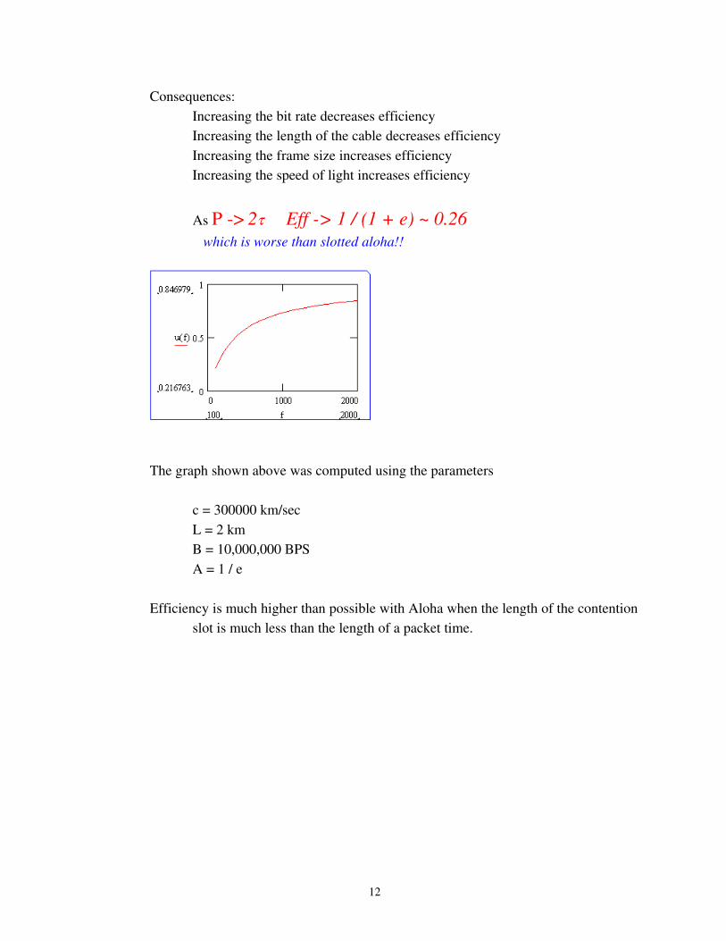
Consequences:Increasing the bit rate decreases efficiencyIncreasing the length of the cable decreases efficiencyIncreasing the frame size increases efficiencyIncreasing the speed of light increases efficiency
As P > 2 Eff > 1 / (1 + e) ~ 0.26 which is worse than slotted aloha!!
The graph shown above was computed using the parameters
c = 300000 km/secL = 2 kmB = 10,000,000 BPSA = 1 / e
Efficiency is much higher than possible with Aloha when the length of the contention slot is much less than the length of a packet time.
12

Real World LAN protocols
Three major approaches have been employed in wired LANs
Early LANsContention (CSMACD / Ethernet)Token passing (Token ring /Token bus)
LANs of the past 10 yearsStar wired and switched (ATM / Switched Ethernet)Wireless (CSMACA / 802.11)
13

Original Ethernet (IEEE 802.3)
1 persistent CSMAwith CD andbinary exponential backoff
slotted time: 2 = 51.2 usecs
after i collisions a station waits between 0 and 2i 1 slotsmax wait is 1023max retries is 16
Frame format (still in use today)7 bytes preamble 101010101 byte Start of frame2 or 6 Destination address (Global vs Local in bit 46)2 or 6 Source address2 Length of data0 1500 payload data0 46 pad (Min frame length = 64 bytes= 51.2 usec at 10 Mbps)4 checksum
Operational constraints (original 10 Base 5) 10 Megabits / secondBase Baseband signaling5 Hundred meter segments2.5 KmMax distance between transceivers4 Repeaters Max along any path
Bridges may be used toextend furtherreduce load on segments
Physical encoding.. Manchester encoded baseband signal
14
Multiple standards have evolved..
10 Base 5 (Original 500M runs / thick wire / vampire taps)
10 Base 2 (200 M runs / thin wire / BNC connectors)
10 Base T (100~150M runs / Cat 3 and 5 UTP / RJ45 Connectors)
100 Base T (100M Cat 3 and 5 UTP )
Gigabit over Cat 5 UTP
Gigabit over fiber.
10 Gigabit over fiber (and Cat 6?)
Fiber links can be considerably longer than UTP but the both the medium and the NICs are considerably more expensive.
Packet size issues
Packet time for 1500 bytes on a 1 Gbps links ~ 12 microsecondsThis creates excessive CPU load on hosts due to interrupt processing.
Solutions include:Large frame sizesInterrupt coalescing
15
Connection mechanisms
Shared bus (10 Base 2/5)
Shared medium hub (10 Base T / 100 Base T)
Receives on one port at a time and transmits input to all outputs
Switched hub (raises the effective throughput of the net)
Can receive on multiple ports at a time and transmits only to dest.
Switch can conduct multiple transfers at one time.
Unicast packets are sent by switch only to destination host.
Store and forward switch
Can Buffer whole packets like a router before retransmitting
Collision problem is effectively removed.
Cutthrough switch
(reduces the latency of the store and forward switch)Forwards packets as soon as address is recognized.
Thus modern "Ethernets" share little more than frame format with their CSMACD precursors
16

Token passing protocols:
General principles
A single token is passed from station to station in a fixed roundrobin patternA station may not transmit until it holds the tokenThe length of time a station may transmit is limitedWhen the time limit is reached or the station has no more data to send, the token is passed.
Operational issues
Initialization how does the first token come to be createdAdding a new system to an operational ringRemoving a system from an operational ring
GracefullyAfter crash
Loss of token (holder powered off or network error)Duplicate token (two rings spliced together)
Existing standards
Token Bus: IEEE 802.4Token Ring: IEEE 802.5FDDI Ring: Similar to IEEE 802.5
Major differences relate to control of the ring operation
Bus: Fully distributed controlRing: Centralized control
Tradeoff is (theoretically) one of robustness vs. simplicity
17
Token Bus:
Stations are attached to a shared medium bus as in Ethernet and use a CSMA listen before transmit protocol.
Exercise: Could this protocol be used in a Wireless environment.
Major issues
Membership management Network initializationAdding new stationOrderly withdrawal of a station
Fault managementLost tokenDuplicate tokenLost successor
Priority management4 Priority classes 0, 2, 4, 6
Token passing is in MAC adddress order from high address to low
Frame format
1+ bytes preamble 101010101 byte Start delimiter1 byte Frame control (Packet type) (Type for TOKEN is wrong in handout ..
should be 82 or 6 Destination address (Global vs Local in bit 46)2 or 6 Source addressn Data4 checksum1 End delimiter
18
Each station maintains a zillion timers and must always know
Its own address (this station) (TS) The next station (NS)The previous station (PS)
Initialization
CLAIM_TOKEN
Stations continually listen for valid transmission, and if one is not heard, they time out and issue CLAIM_TOKEN.
If a collision occursContention is resolved using a quartiary countdownA CLAIM_TOKEN frame contains up to 4 extra slots whose presence usage depends on "current" two address bitsA station listens after completing its frame.If (continuing transmission heard)
GIVE UPelse
Repeat using next two address bits
If no collision the transmitting station now owns the token
19

Adding a new station
SOLICIT_SUCCESSOR_1( NS) (having a 1 slot response window)
May or may not be issued each Token rotationInvites stations between TS and NS to attempt to join busStation wishing to join responds with SET_SUCCESSOR
If collision the token holder Transmits RESOLVE_CONTENTION which has a 4 slot response
windowColliders reply in slot # associated with 1st two address bits.If collision repeated
Continue using next address bits until resolved.
Lowest numbered station in the ring uses a SOLICIT_SUCCESSOR_2
SOLICIT_SUCCESSOR_2(NS) (has two response windows)
Stations with address lower than TS can reply in window 1Stations with address higher than TS can reply in window 2
20
Orderly exit
Send SET_SUCCESSOR(PS) to PS
Lost successor
Issue WHOFOLLOWS( NS) specifying current successorIf response received update NS pass tokenIf no response issue SOLICITSUCCESSOR2
Any station can respondIf one does a two station ring is created
Lost Token
Time out and CLAIM TOKENRebuild ring
Duplicate token
Generally caused by partitioned bus being rejoined.Generally detected by a collision occurrenceAction is to drop tokenMay result in lost token
21
Priority control (simplified):
Certain proportion of total Token Holding Time can be reserved for each type of traffic Priority 6, 4, 2, and 0.
Problem: If not busy you might has well be able to send data of other classes:
THT = token holding time: the maximum time that a station can hold the token to transmit class 6 data.
TRT4 = token rotation time for class 4: maximum time that a token can take to circulate and still allow class 4 transmissions.Class 4 time = TRT4 (Time of last rotation + time of class 6
transmission)
N * THT > TRT4 => Class 4 traffic may be starved.
Example:
N = 10 stationsTHT = 20 msec
If all stations have always have class 6 traffic it will take 200 msec for a complete rotation. If TRT4=220 then there will be a total of 20msec per rotation for class 4 traffic.
22

Token Ring
Basics of operation
No contention at all
Each station has a store and forward buffer
Tx can be driven from the store and forward buffer (idle)onboard packet buffers (transmitting)
Rx can be directed tothe store and forward buffer (idle)onboard packet buffers (receive)the "bit bucket" (drain)
A station can't transmit until it inverts token bit becoming the token holder
The holder can inject a packetThe holder must drain each packet that it sends.The holder recreates the token after THT (def 10ms) expires or no more dataThe ring must be long enough to hold the token
802.54 or 16 Mbits (book says 1 or 4) now available in 100Mbit flavorsTypically hooked up via wire centers (Hubs)Multiple wire centers may be cabled together
Packet format
Token bit is 4th bit in AC byteAddressing as in 802.3 and 802.4FS (frame status) byte at end carries
A Address recognizedC Frame copied bits
23

Ring maintenance
Active monitor election
Station transmits CLAIM_TOKEN stream and listens:Sees own address
SuccessSees higher address desists sending and goes into repeater modeSees lower address continues sendingHighest address station eventually wins:
Ring maintenance issues
Loss of active monitorOrphan framesLoss of tokenToken priority stuck high
Active monitor functions
Periodically issue ACTIVE_MONITOR_PRESENTRegenerate tokenSet M=1 on each valid frame or high priority tokenM=1 on frame or token
Eat frame or token Regenerate token
Evidence of active monitor Go to standby status
Insert delay bits as required
24
Priority control
8 priority levelsTwo fields in each AC byte
Priority field Reservation field
A station with high priority traffic can make a reservationStation holding the token on seeing reservation must
Remember stateSet priority to reservation Immediately release token
Station issuing a high priority token is responsible for reducing the priority
25
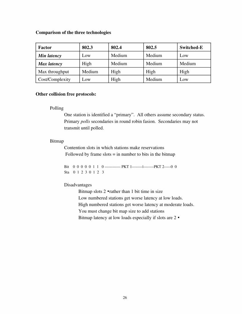
Comparison of the three technologies
Factor 802.3 802.4 802.5 SwitchedEMin latency Low Medium Medium Low
Max latency High Medium Medium MediumMax throughput Medium High High HighCost/Complexity Low High Medium Low
Other collision free protocols:
Polling One station is identified a “primary”. All others assume secondary status.Primary polls secondaries in round robin fasion. Secondaries may not transmit until polled.
BitmapContention slots in which stations make reservations Followed by frame slots = in number to bits in the bitmap
Bit 0 0 0 0 0 1 1 0 PKT 1|PKT 20 0 Sta 0 1 2 3 0 1 2 3
DisadvantagesBitmap slots 2 rather than 1 bit time in sizeLow numbered stations get worse latency at low loads.High numbered stations get worse latency at moderate loads.You must change bit map size to add stationsBitmap latency at low loads especially if slots are 2
26
BRAP = BRAM+MSAP
Station begin transmission immediately after setting bitmap bit.Bitmap restarts following transmission with the station after the one that just
transmitted.Disadvantages remaining:
Bitmap slots 2 rather that 1 bit time in sizeYou must change bit map size to add stationsBitmap latency at low loads especially if slots are 2
Binary countdown
Bit map = number of bits in a station addressIf a station has a 1 bit at current slot it writes it into the slot.... Until it sees a 1 bit written in a slot where it has a zero.In that case it gives up.Result: Highest numbered ready station wins.Obviously this is unfair... Solution
Use virtual station numbers.After a successful Xmit become virtual station 0.All stations between transmitter and 0 get incremented.===> Highest priority station is the one that hasn't transmitted in the
longest time.
27
Other MAC protocols
FDDI Optical token ring 100 Mbits / secondSender regenerates token at end of transmission ==> multiple packets possible
on RingFormerly used to link 802.x LANS in a large enterprise/Now replaced by GigE
Satellite networks
FDM, STDM ok for phone circuits
Adaptive reservation schemes better for bursty data traffic.Objective of such schemes:
Heavy <Load> LightTDM Aloha
A number of adaptive protocols have been proposed, but in the real world FDM, STDM, ALOHA and CDMA have been used.
28
Wireless Networks
The Electromagnetic Spectrum
Can be viewed as sinusoidal "waves" passing through spaceIncludes radio, infrared, visible light, ultra violet light, Xray, Gamma rayFrequency, f = number of complete cycles of the sine wave / second measured in HzWavelength l = length a of complete cycle of the sine wave in meters
Fundamental relationship is fl = c.
If l is measured in meters and f in Mhz fl = 300.
A channel is a continuous range of frequencies [f1, f2] or equivalently wavelengths[l2, l1]
The bandwidth of a channel is f2 f1.
The maximum number of bits per Hz is determined by the SNR typically in the range of 1 to 16 for wired and wireless channels (c.f. Dial modems)
29
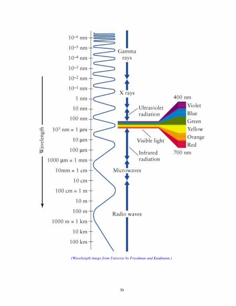
(Wavelength image from Universe by Freedman and Kaufmann.)
30
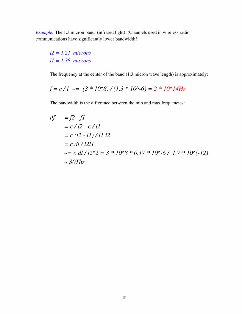
Example: The 1.3 micron band (infrared light) (Channels used in wireless radio communications have significantly lower bandwidth!
l2 = 1.21 micronsl1 = 1.38 microns
The frequency at the center of the band (1.3 micron wave length) is approximately:
f = c / l ~= (3 * 10^8) / (1.3 * 10^6) = 2 * 10^14Hz
The bandwidth is the difference between the min and max frequencies:
df = f2 f1 = c / l2 c / l1 = c (l2 l1) / l1 l2 = c dl / l2l1 ~= c dl / l2^2 = 3 * 10^8 * 0.17 * 10^6 / 1.7 * 10^(12) ~ 30Thz
31
Spread spectrum techniques
Basic objective Distribute signal energy across a relatively wide range of frequencies.
Motivations
• secure communications, • increased resistance to natural interference and to jamming, • and to prevent detection of communications
Implementations
• Frequency hopping (primarily used in military applications)• OFDM (parallel transmission on multiple subchannels)• direct sequence spread spectrum (probably the most difficult to understand)
Direct sequence
• Each bit is transmitted using a sequence of "subbits" called chips. • The specific sequence (e.g. + + +) that is defined to mean "1" bit • This sequence doesn't change during operation. • The complement of the sequence ( + + + + ) then represents a "0" bit.• Different transmitters use different chipping sequences • The chipping sequences are designed to spread the signal power.
32

CDMA Code Division Multiple Access
A direct sequence spread spectrum technique in which it is (theoretically) possible for all stations to send simultaneously and nondestructively.
Bit times are divided into N Chips (typically 64 or 128)Each station has a unique chip sequence of 64 or 128 (+1/1)'s To send a 1 bit the station sends its chip sequenceTo send a 0 bit the station sends the complement of its chip sequenceChip sequences are mutually orthogonal with respect to the standard dot product.
(C1 dot C2) = 0(C1 dot ~C2) = 0(C1 dot C1) = N(C1 dot ~C1) = N
Receiver may receive superimposed signalsC1 + ~C2 + C3 + ~C4
Receiver dots the sum with the desired sender's Chip sequence(C1 + ~C2 + C3 + ~C4) dot C3 = C3 dot C3
Example:
A: 1 1 1 +1 +1 1 +1 +1B: 1 1 +1 1 +1 +1 +1 1C: 1 +1 1 +1 +1 +1 1 1D: 1 +1 1 1 1 1 +1 1
If some chips are received in error then the dot product may be somewhere N and N. If the value is almost N, then its likely a 1 bit was sent. If its nearly N, then likely a 0 bit was meant. If the dot product ~0 then who knows??
33
PN sequences
In practice it is common to use PN (pseudorandom) noise sequences instead of dedicated chipping sequences.
• The sequences consist of a mix of 1 and +1's• To send a 1 bit the sequence itself is sent• To send a 0 bit the inverse of the sequence is sent• The receiver performs the dot product of the received sequence with the known PN
sequence
A large postitive result > 1A large negative result > 0
34
Wireless LANs IEEE 802.11
Original 802.11 physical layer used three basic physical layer technologies:
InfraredMicrowave (2.4 Ghz) Industrial, Scientific, Medical (ISM) Band
Frequency hopping spread spectrumDirect sequence spread spectrum
Data rates limited to 1 2 Mbps
Newer additions include
802.11a (Orthogonal FDM) (OFDM using 52 subchannels of 1 Mhz bandwidth providing up to 54 Mbps on 5 Ghz UNNI (unlicensed National Information Infrastructure) band
802.11b (HR DSSS (High rate DSSS)) up to 11 Mbps
802.11g (OFDM) up to 54 Mbps on 2.4 Ghz ISM band.
802.16 > WiMAX SC/OFDM/OFDMA using 192/256 subchannels
35
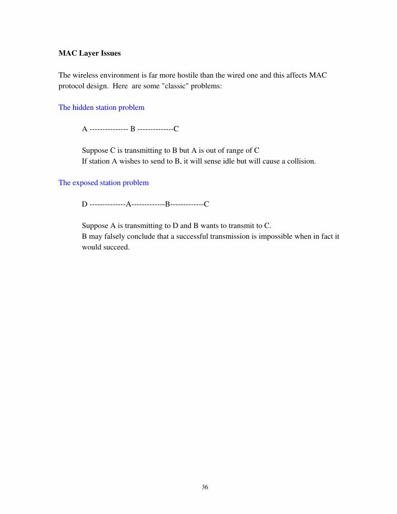
MAC Layer Issues
The wireless environment is far more hostile than the wired one and this affects MAC protocol design. Here are some "classic" problems:
The hidden station problem
A B C
Suppose C is transmitting to B but A is out of range of CIf station A wishes to send to B, it will sense idle but will cause a collision.
The exposed station problem
D ABC
Suppose A is transmitting to D and B wants to transmit to C.B may falsely conclude that a successful transmission is impossible when in fact it would succeed.
36
Operational modes of 802.11 networks
Ad hoc mode
An 802.11 networking framework in which devices or stations communicate directly with each other, without the use of an access point (AP). Ad hoc mode is also referred to as peertopeer mode or an Independent Basic Service Set (IBSS). Ad hoc mode is useful for establishing a network where wireless infrastructure does not exist or where services are not required.
Infrastructure mode:
A mode in which devices communicate with each other via an Access Point (AP) which is typically connected to a wired network. When one AP is connected to wired network and a set of wireless stations it is referred to as a Basic Service Set (BSS).
The ESS
An Extended Service Set (ESS) is a single logical network segment (also known as a subnet), It is identified by its Service Set Identifier (SSID). If the available physical areas of the wireless APs in an ESS overlap, then a wireless client can roam, or move from one location (with a wireless AP) to another (with a different wireless AP) while maintaining Network layer connectivity. For example, cuairnet and tigernet are SSIDs and the campus wireless networks are ESS's.
Within infrastructure mode one of two types of coordination function is used:
DCF Distributed Coordination Function: The MAC procedure is distributed among all the wireless stations.
PCF Point Coordination Function: A base station also called an Access Point (AP) controls all access to the channel using the polling technique.
DCF is mandatory but PCF is an optional add on. All “real world” wireless LAN's use DCF.
37
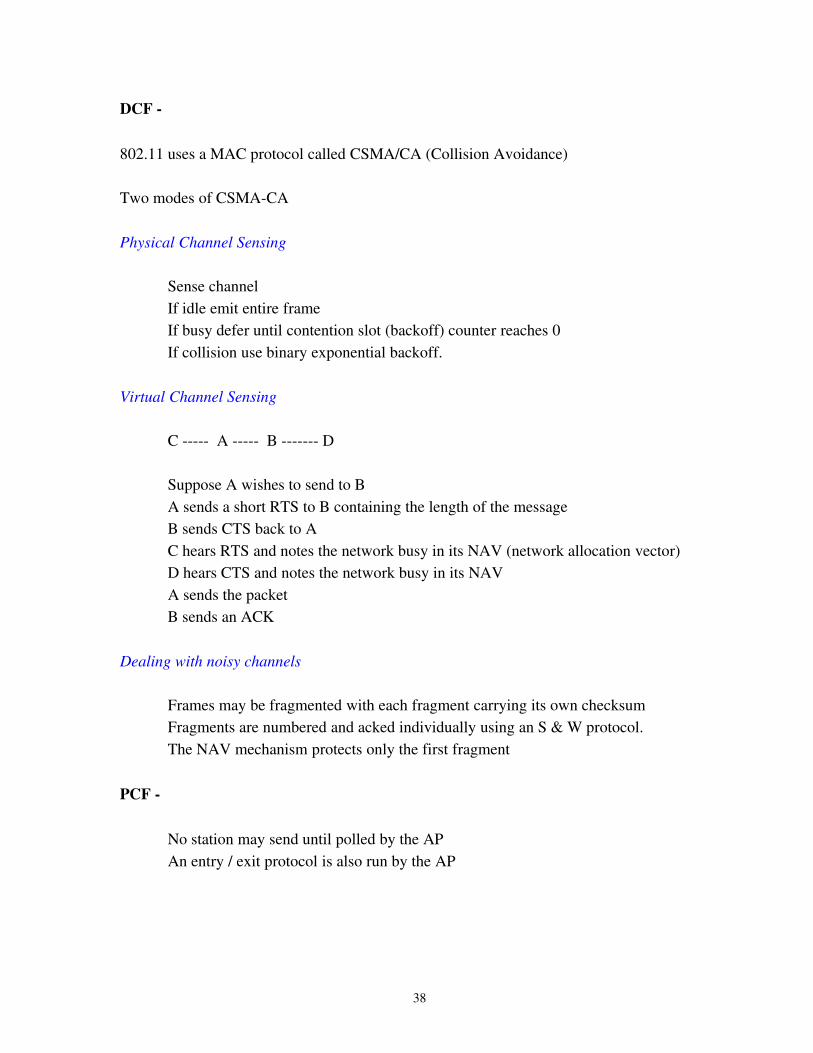
DCF
802.11 uses a MAC protocol called CSMA/CA (Collision Avoidance)
Two modes of CSMACA
Physical Channel Sensing
Sense channelIf idle emit entire frameIf busy defer until contention slot (backoff) counter reaches 0If collision use binary exponential backoff.
Virtual Channel Sensing
C A B D
Suppose A wishes to send to BA sends a short RTS to B containing the length of the messageB sends CTS back to AC hears RTS and notes the network busy in its NAV (network allocation vector)D hears CTS and notes the network busy in its NAVA sends the packetB sends an ACK
Dealing with noisy channels
Frames may be fragmented with each fragment carrying its own checksumFragments are numbered and acked individually using an S & W protocol.The NAV mechanism protects only the first fragment
PCF
No station may send until polled by the APAn entry / exit protocol is also run by the AP
38
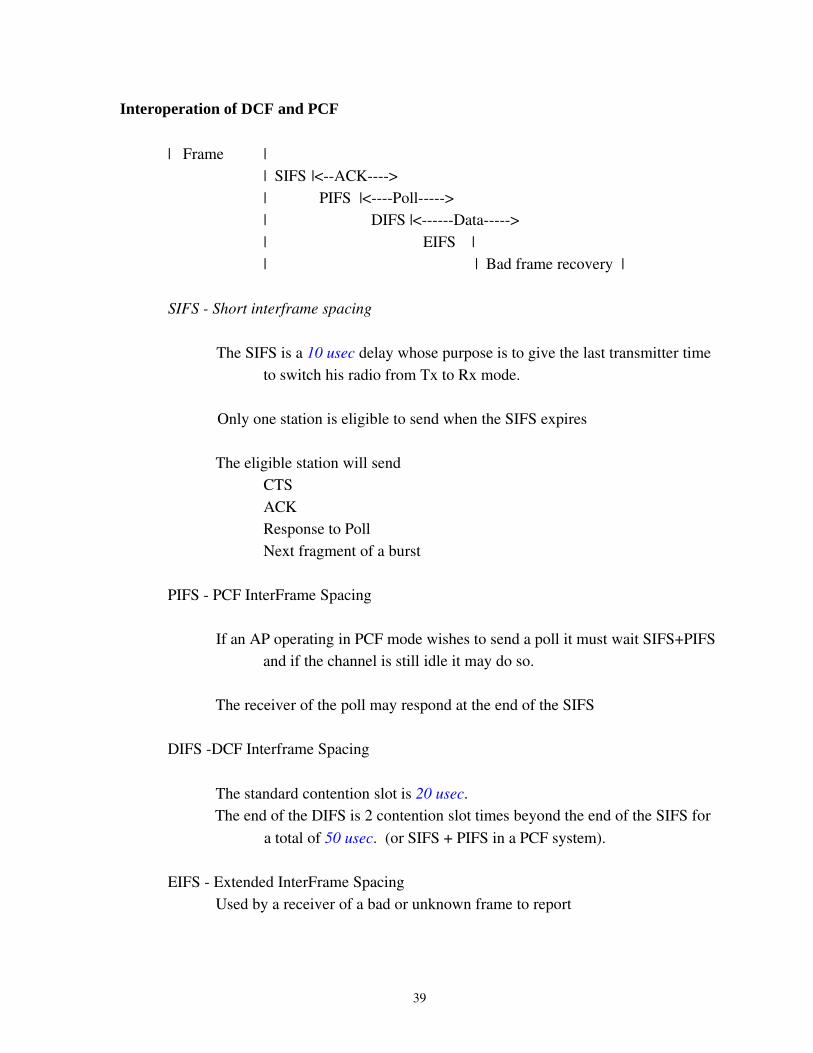
Interoperation of DCF and PCF
| Frame | | SIFS |<ACK>| PIFS |<Poll>| DIFS |<Data>| EIFS || | Bad frame recovery |
SIFS Short interframe spacing
The SIFS is a 10 usec delay whose purpose is to give the last transmitter time to switch his radio from Tx to Rx mode.
Only one station is eligible to send when the SIFS expires
The eligible station will sendCTSACKResponse to PollNext fragment of a burst
PIFS PCF InterFrame Spacing
If an AP operating in PCF mode wishes to send a poll it must wait SIFS+PIFS and if the channel is still idle it may do so.
The receiver of the poll may respond at the end of the SIFS
DIFS DCF Interframe Spacing
The standard contention slot is 20 usec. The end of the DIFS is 2 contention slot times beyond the end of the SIFS for
a total of 50 usec. (or SIFS + PIFS in a PCF system).
EIFS Extended InterFrame SpacingUsed by a receiver of a bad or unknown frame to report
39
The 802.11 contention algorithm
A dual persistence approach is employed
● Limits on the size of the contention window CW are defined by CWmin = 31 slots and CWmax = 1023 slots. The current size of the contention window is called CW. CW is reset to Cwmin after a successful transmission and is doubled after each collision.
● When a station becomes ready to send, it senses the carrier for DIFS amount of time and if nothing is heard it transmits.
● If it hears a transmission in progress, it waits until the Tx ends and computes a random number of slots wcount between 0 and CW (Where CW is initially CWmin).
● It listens through the SIFS and the DIFS and if it hears a transmission commence it defers until the end of that transmission. While no transmission is heard, it decrements wcount for each 20 usec slot time that passes.
● When wcount reaches 0, the station will transmit.
● If another station starts transmitting before wcount reaches 0, the decrementing of wcount is suspended until the frame, the following sifs and pifs have passed at which time it resumes where it left off.. In this way the last come first served behavior is avoided.
● A collision is inferred from a missing CTS or ACK. CW is doubled when a collision occurs until it reaches CWmax. CW is reset to CWmin when a transmission succeeds.
40
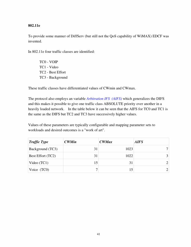
802.11e
To provide some manner of DiffServ (but still not the QoS capability of WiMAX) EDCF was invented.
In 802.11e four traffic classes are identified:
TC0 VOIPTC1 VideoTC2 Best EffortTC3 Background
These traffic classes have differentiated values of CWmin and CWmax.
The protocol also employs an variable Arbitration IFS (AIFS) which generalizes the DIFS and this makes it possible to give one traffic class ABSOLUTE priority over another in a heavily loaded network. In the table below it can be seen that the AIFS for TC0 and TC1 is the same as the DIFS but TC2 and TC3 have successively higher values.
Values of these parameters are typically configurable and mapping parameter sets to workloads and desired outcomes is a "work of art".
Traffic Type CWMin CWMax AIFS
Background (TC3) 31 1023 7
Best Effort (TC2) 31 1022 3
Video (TC1) 15 31 2
Voice (TC0) 7 15 2
41
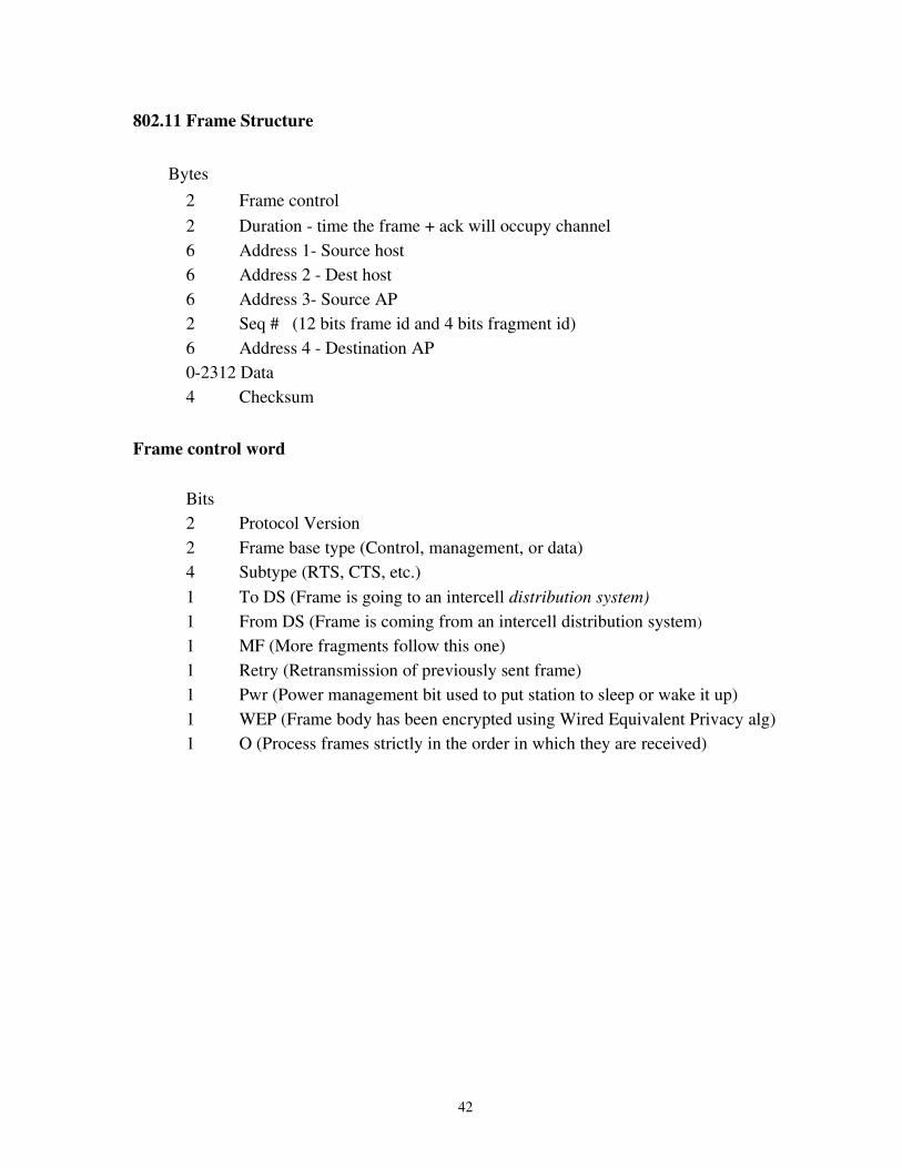
802.11 Frame Structure
Bytes2 Frame control2 Duration time the frame + ack will occupy channel6 Address 1 Source host6 Address 2 Dest host6 Address 3 Source AP2 Seq # (12 bits frame id and 4 bits fragment id)6 Address 4 Destination AP02312 Data4 Checksum
Frame control word
Bits2 Protocol Version2 Frame base type (Control, management, or data)4 Subtype (RTS, CTS, etc.)1 To DS (Frame is going to an intercell distribution system)1 From DS (Frame is coming from an intercell distribution system)1 MF (More fragments follow this one)1 Retry (Retransmission of previously sent frame)1 Pwr (Power management bit used to put station to sleep or wake it up)1 WEP (Frame body has been encrypted using Wired Equivalent Privacy alg)1 O (Process frames strictly in the order in which they are received)
42
802.11 Services
Intercell services
Association ability of a mobile station to connect to a base station. Parameters include SSID, data rate, PCF capabilities, power management needs.
Disassociation breaking the connection. Can be triggered when either the mobile station or the base station goes down.
Reassociation changing of base station. Occurs when a mobile station changes cells while up.
Distribution a routing service provided by the wired distribution system (DS)
Integration performing required packet reformatting at a base station. (e.g. reassembly of fragments prior to forwarding on an ethernet).
Intracell services
Authentication A mechanism by which stations must authenticate before being accepted by the base station. Not in the original standard and potentially a nuisance to internet cafe users. Its absence has led to "warchalking"
Deauthentication Occurs when a station disassociates or reassociates.
Privacy The flawed WEP algorithm
Data delivery best effort service like ethernet.
43

Security issues
The 802.11 physical layer is like an early Ethernet a bus in which all stations hear all transmissions
It is less secure than early Ethernet in that any unauthorized person can (almost) unobtrusively monitor net traffic.
See newarchitect.html in the class directory for an example of the problem.
A potential solution is to encrypt each packet.
WEP (using a variant of the RC4 encryption algorithm) was chosen as the standard.
Unfortunately WEP turned out to be a defective implementation.See wepweaknesses.pdf and crackingwep.pdf in the class directory.See the airsnort hack kit on the web.
Current solution: Be sure to use SSL tools (ssh, scp, etc) which use a nonbroken implmentation
of RC4
802.11i > 802.112007 defines a new encryptions standard (WPA) WiFi prototected access that is based on the Advanced Encryption Standard (AES) instead of RC4. It is available in current products and has yet to be broken.
The problem of disseminating and maintaining control of the security keys to a large population of users remains challenging.
Other ways of enhancing security include:
Don't broadcast the SSID.Limit associations to stations having MAC addresses in an access list.
44

Other wireless technologies
802.16 – (later WiMAX) Designed to provide broadband wireless service to fixed stations (i.e. a MAN)
Later versions support mobility.MAC layer protocol is a variant of the DOCSIS protocol.
Bluetooth Designed to connect cell phones to computer modems (a Pico Net or Personal Area Network)
Links are limited to 10 m. Uses 79 channels of 1 Mhz each in the 2.4 Ghz ISM band.
45
Data over Cable TV systems
Defined by the Data of Cable Service Interface Specification (DOCSIS).
The physical layer medium is a shared access cable.
MAC functions are controlled by a “head end” device called a Cable Modem Terminating System (CMTS).
User attachment points are dual ported devices called Cable Modems (CMs) that run
DOCSIS on the cable sideEthernet on the user side
Traffic flow is always CM <> CMTS never CM <> CM
Typical aggregate bandwidth shared by all users in DOCSIS 1.1 systems
30 Mbps downstream – from the CMTS5 Mbps upstream – toward the CMTS
ATDM bandwidth sharing is enforced by the CMTS with typical maximum values of
3 Mbps downstream > now 6 Mbps or more256 Kbps upstream > now 768 Kbps or more.
Downstream bandwidth sharing is simple because the CMTS is the only Tx'er
The CMTS uses (possibly prioritized and or deficit) round robin service to deliver packets to CMs
46
Upstream channel access
Upstream bandwidth allocation is not so simple, because all CM's must share the same cable.
The upstream channel is ATDM multiplexed in fixed time units called minislots. The minislot is a power of two mulitple number of basic ticks.The basic tick is 6.25 usec.
Typical values:Upstream bit rate 5.12 * 10 6 bpsBasic ticks per minislot 4Minislot length 25 usecBytes / minislot 16
Since a standard TCP/IP packet requires at least 20 bytes each of IP and TCP header a minislot is not intended to carry an entire packet. It should be instead viewed as somewhat analogous to an ATM cell.
47
Allocation of minislots
Usage of individual minislots is dictated by a special control packet called the MAP which is sent on the downstream channel every few milliseconds and describes the near future allocation of slots in the upstream channel. The set of minislots described in a single MAP is called a frame.
Frame time is typically in the range 2 – 10 msec.
Upstream uses of minislots include:
Grants to CMs for upstream data transmissionContention Slots for new CMs to request to come onlineUnsolicited grants for service such as cable telephones (UGS)Grants for dedicated slots in which upstream bandwidth can be requested in a contention free way (RTPS = real time polling service). Contention Slots in which CMs may request upstream bandwidth
48

When a cable modem has best effort upstream traffic send it:
Generates a random number backoff based upon its current backoff window sizeStarting with the next MAP it waits backoff contention slots (which may be multiple
map times) and then makes its request in the next contention slot. If successful, the request will be acknowledged (but not necessarily granted) in the
next MAP. A collision is inferred by the absence of an acknowledgment. The CM must double
its backoff window and start over.
Refinements
The min and max sizes of the backoff window are specified periodically by the CMTS in special control messages and so may be dynamic.
A CM can request upstream grants for a maxium of one packet at a time, but a piggy backing facility allows the station to request additional grants at the end of the current packet without having to use the contention mechanism.
Multiple IP frames can be concatenated in a single MAC layer traffic burst.
49
QoS in DOCSIS and WiMAX
Upstream Service categories include:
UGS a service flow receives unsolicited grants at a fixed rate.
RTPS – a service flow receives dedicated slots in which to request upstream service at a fixed rate (but doesn't have to use it). A RTPS flow cannot make contention requests.
NRTPS a service flow receives periodic opportunities to request upstream service but can also use the contention mechanism.
BE – only the contention mechanism is used.
50

Assigning QoS attributes
Classifier rule Used to associate packets with particular service flows based upon source or destination MAC address, IP address, Port address.
Service flow Has a service category (UGS, RTPS, etc) and a service parameters such as minimum guaranteed throughput, maximum permitted throughput, maximum allowed jitter.
Typically service flows and classifier rules must be manually set up by a system administrator. Sensible defaults for generic categories (VoIP, best effort, etc) can facilitate the problem to a certain degree.
Dynamic Service Activation (DSA)
UGS and RTPS services consume upstream bandwidth whenever they are active.
A telephone service should consume bandwidth only when a call is in progress.
Therefore, provisioning must be a two step process. The system administrator must provision a service flow but DSA protocols between the CM and CMTS activate and deactivate the service automatically.
In this way bandwidth is not consumed by inactive but provisioned flows.
51