Embed Size (px)
Citation preview

IAEA-TECDOC-1403
The long term stabilization ofuranium mill tailings
Final report of a co-ordinated research project2000–2004
August 2004

IAEA-TECDOC-1403
The long term stabilization ofuranium mill tailings
Final report of a co-ordinated research project2000–2004
August 2004

The originating Section of this publication in the IAEA was:
Waste Technology Section International Atomic Energy Agency
Wagramer Strasse 5 P.O. Box 100
A-1400 Vienna, Austria
THE LONG TERM STABILIZATION OF URANIUM MILL TAILINGS IAEA, VIENNA, 2004 IAEA-TECDOC-1403. ISBN 92–0–108904–X
ISSN 1011–4289 © IAEA, 2004
Printed by the IAEA in Austria August 2004

FOREWORD
The IAEA attaches great importance to the dissemination of information that can assist Member States with the development, implementation, maintenance and continuous improvement of systems, programmes and activities that support the nuclear fuel cycle and nuclear applications. This includes managing the legacy of accidents and past practices, including that from uranium mining and milling.
A comprehensive IAEA programme of work covers multiple aspects of environmental remediation:
technical and non-technical factors, including costs, that influence environmental remediation strategies and pertinent decision making;
site characterization techniques and strategies; assessment of remediation technologies; techniques and strategies for post-remediation compliance monitoring; special issues such as the remediation of sites with dispersed radioactive contaminations or
mixed contamination by hazardous and radioactive substance and of uranium mining and milling sites.
In the past, often little or no care was taken to isolate uranium mill tailings from the environment. In order to address the specific problems surrounding the disposal of uranium mill tailings, the IAEA developed a co-ordinated research project (CRP) in this area. CRPs are intended to bring together researchers from different Member States with the view to share and disseminate the experience in solving problems of common interest.
The aim of the CRP on the long term stabilization of uranium mill tailings was to contribute to the development of conceptual, technical, and management solutions that:
render tailings more inert over prolonged time-spans; render impounded materials and engineered structures stable;
over prolonged time spans; minimize the need for active maintenance; can be applied in a remediation context; and support solutions that are technically and economically feasible.
The IAEA wishes to express its thanks to all Chief Scientific Investigators and other contributors to the work. Special thanks are due S. Needham, Australia, who under contract provided a seed review of tailings disposal techniques, and to H. Cotzee and R. Gatzweiler, who reviewed an early draft.
The IAEA officer responsible for this technical publication was W.E. Falck of the Division of Nuclear Fuel Cycle and Waste Management.

EDITORIAL NOTE
This publication has been prepared from the original material as submitted by the authors. The views expressed do not necessarily reflect those of the IAEA, the governments of the nominating Member States or the nominating organizations.
The use of particular designations of countries or territories does not imply any judgement by the publisher, the IAEA, as to the legal status of such countries or territories, of their authorities and institutions or of the delimitation of their boundaries.
The mention of names of specific companies or products (whether or not indicated as registered) does not imply any intention to infringe proprietary rights, nor should it be construed as an endorsement or recommendation on the part of the IAEA.
The authors are responsible for having obtained the necessary permission for the IAEA to reproduce, translate or use material from sources already protected by copyrights.
CONTENTS
1. INTRODUCTION ............................................................................................................ 1
1.1. Background......................................................................................................... 1 1.2. Objectives ........................................................................................................... 2
1.2.1. Overall objective..................................................................................... 2 1.2.2. Scientific research objectives.................................................................. 3
1.3. The focus of the CRP.......................................................................................... 41.4. The structure of the CRP .................................................................................... 5
2. HISTORICAL PRACTICES ............................................................................................ 6
2.1. The ‘ages’ of uranium production ...................................................................... 6 2.2. Age, number, geographic and climatic distribution of uranium mill
tailings piles ........................................................................................................ 82.3. Relationship of tailings piles to mine and mill facilities .................................. 11 2.4. Historical approaches to tailings placements.................................................... 12
2.4.1. No effective containment...................................................................... 12 2.4.2. Low embankments ................................................................................ 13 2.4.3. Topographic depressions ...................................................................... 13 2.4.4. Valley fill .............................................................................................. 13 2.4.5. Ring dyke or turkey nest dam............................................................... 13 2.4.6. Mined out pit......................................................................................... 13 2.4.7. Underground mine back-fill.................................................................. 14 2.4.8. Deep lake or river ................................................................................. 14
2.5. Classification of uranium mill tailings ............................................................. 14 2.6. Inappropriate uses of uranium mill tailings ...................................................... 15
3. ENVIRONMENTAL IMPACTS ................................................................................... 16
3.1. Events that have led to environmental impacts ................................................ 16 3.2. Impacts on human health .................................................................................. 193.3. Potential radiological impacts upon the natural environment .......................... 21 3.4. Toxic and hazardous compounds in tailings and their potential impacts ......... 23
4. REMEDIATION PROGRAMMES TO REDUCE HAZARDS FROM HISTORICAL URANIUM MILL TAILINGS .............................................................. 24
4.1. Driving forces for remedial work ..................................................................... 24 4.2. Remedial work undertaken............................................................................... 25 4.3. Examples from the USA................................................................................... 26 4.4. Examples from France...................................................................................... 26 4.5. Examples from Germany.................................................................................. 26 4.6. Examples form the Czech Republic ................................................................. 26 4.7. Examples from Australia .................................................................................. 27 4.8. Evaluation of the remedial works at historic tailings piles............................... 27
5. PRESENT DAY PRACTICES....................................................................................... 28
5.1. Objectives ......................................................................................................... 28 5.2. Standards for radiological and environmental protection................................. 29 5.3. Member States’ regulations, standards and guidelines..................................... 30

5.4. Current approaches to tailings containment ..................................................... 325.4.1. Less-favoured options........................................................................... 32 5.4.2. Above ground disposal ......................................................................... 33 5.4.3. Below ground containment................................................................... 365.4.4. Deep lake .............................................................................................. 395.4.5. Purpose-built containment .................................................................... 39
5.5. Current approaches to stabilise and isolate uranium mill tailings .................... 405.5.1. Design objectives .................................................................................. 40 5.5.2. Containment preparation....................................................................... 40 5.5.3. Tailings preparation .............................................................................. 41 5.5.4. Tailings discharge and deposition......................................................... 43 5.5.5. Tailings consolidation........................................................................... 44 5.5.6. Tailings surface treatment..................................................................... 46 5.5.7. Decant water treatment ......................................................................... 47 5.5.8. Seepage control..................................................................................... 47 5.5.9. Covers ................................................................................................... 48
6. OUTSTANDING ISSUES ............................................................................................. 53
6.1. Overview .......................................................................................................... 53 6.2. Issues relating to the physical properties of tailings......................................... 53 6.3. Issues relating to containment .......................................................................... 56 6.4. Issues relating to tailings chemistry.................................................................. 57 6.5. Passive systems................................................................................................. 58
7. NEW APPROACHES AND RESEARCH..................................................................... 59
7.1. Overview .......................................................................................................... 59 7.2. Design and siting of containments.................................................................... 60 7.3. Physical stabilization ........................................................................................ 60
7.3.1. Consolidation ........................................................................................ 61 7.3.2. Paste technology ................................................................................... 62 7.3.3. Grouting ................................................................................................ 63
7.4. Chemical stabilization ...................................................................................... 63 7.4.1. Overview............................................................................................... 63 7.4.2. Geochemical impacts ............................................................................ 64 7.4.3. Fixation technologies ............................................................................ 65
7.5. Encapsulation and covers ................................................................................. 67 7.6. Effluent containment and treatment ................................................................. 68 7.7. Management systems........................................................................................ 69 7.8. Long term research priorities............................................................................ 70
8. PERFORMANCE ASSESSMENT OF IMPOUNDMENTS......................................... 70
8.1. Purpose of performance assessment ................................................................. 70 8.2. Conceptual approaches ..................................................................................... 70 8.3. Performance assessment approaches ................................................................ 71 8.4. Baseline data and regional characterization ..................................................... 72 8.5. Monitoring ........................................................................................................ 72 8.6. Radiological impact .......................................................................................... 73
8.6.1. Concept of critical groups..................................................................... 73 8.6.2. Scenarios ............................................................................................... 73
8.7. Non-radiological impacts ................................................................................. 75

9. SUMMARY.................................................................................................................... 75
9.1. Historical practices ........................................................................................... 75 9.2. Environmental impacts ..................................................................................... 769.3. Remediation programmes................................................................................. 77 9.4. Present day practices ........................................................................................ 789.5. Outstanding issues ............................................................................................ 79 9.6. New approaches................................................................................................ 79 9.7. Performance assessment ................................................................................... 80
10. CONCLUSIONS ............................................................................................................ 81
REFERENCES......................................................................................................................... 83
GLOSSARY............................................................................................................................. 99
ANNEX I. BRAZIL: A CASE STUDY ON THE URANIUM TAILINGS DAM OF POÇOS DE CALDAS URANIUM MINING AND MILLING SITE............... 101 H.M. Fernandes, M.R. Franklin, G.M. Leoni, M. Almeida
ANNEX II. CANADA: CAMECO RABBIT LAKE IN-PIT TAILINGS MANAGEMENT FACILITY — TAILINGS INJECTION TRIAL PROGRAMME ................................................................................................... 121 P. Landine
ANNEX III. CHINA: STUDIES OF BENTONITE AND RED SOILS AS CAPPING OF THE URANIUM MILL TAILING IMPOUNDMENTS.............................. 145 Zhijian Wen, Zhangru Chen, Zhengyi Liu, Guoliang Chen
ANNEX IV. CZECH REPUBLIC: PREDICTING THE LONG TERM STABILIZATION OF URANIUM MILL TAILINGS ................................................................... 161 J. Trojá ek
ANNEX V. FRANCE: METHODOLOGY TO ASSESS THE RADIOLOGICAL IMPACT OF DISPOSALS OF URANIUM MILL TAILINGS AFTER REMEDIATION (SHORT TERM IMPACT).................................................. 181 A.C. Servant
ANNEX VI. GERMANY: DEVELOPMENT OF TECHNOLOGIES FOR IN SITU REMEDIATION OF CONTAMINATED SITES BY DIRECTED FORMATION OF NATURALLY OCCURRING SLIGHTLY SOLUBLE MINERALS ...................................................................................................... 195 G. Ziegenbalg
ANNEX VII. KAZAKHSTAN: DEVELOPMENT OF METHOD OF COVERING RAISING DUST BEACHES OF RADIOACTIVE WASTES STORAGE OUT OF OPERATION..................................................................................... 209 A. Gagarin

ANNEX VIII. REPUBLIC OF KOREA: REMEDIATION OF URANIUM MILL TAILINGS USING NATURAL AND ORGANO-CLAYS .......................... 223 Sang June Choi, Young Hun Kim
ANNEX IX. POLAND I: IMPROVEMENT OF SOIL PROPERTIES APPLIED TO CAPPING AND MULTI-LAYER BARRIERS............................................. 233 J. Koszela
ANNEX X. POLAND II: ROOM TEMPERATURE CERAMICS, THE BREAKTHROUGH MATERIAL FOR LONG TERM STABILIZATION AND ISOLATION OF LOW-LEVEL URANIUM RESIDUES? ................... 249 A. Piestrzynski
ANNEX XI. RUSSIAN FEDERATION: POLYMERIC COATS FOR THE STABILIZATION OF CONTAMINATED SURFACES................................ 265 S.V. Mikheykin
ANNEX XII. UKRAINE: RESEARCH AND DEVELOPMENT OF MEASURES TO BE TAKEN FOR LONG TERM STABILIZATION AND ISOLATION OF URANIUM MILL TAILINGS ................................................................... 281 G. Maslyakov
ANNEX XIII. UNITED STATES OF AMERICA: RESEARCH AND DEVELOPMENT OF MEASURES TO BE TAKEN FOR LONG TERM STABILIZATION AND ISOLATION OF URANIUM MILL TAILINGS....................................................................... 297 S.R. Metzler
LIST OF PARTICIPANTS .................................................................................................... 311

1. INTRODUCTION
1.1. Background
Large volumes of low activity milling residues, such as mill tailings, are produced –sometimes exceeding millions of tonnes at a single uranium mining/milling facility, in particular, when uranium is only a by-product. The common mode of disposal is in near-surface impoundments in the vicinity of the respective mine or mill [1]. Such impoundments were often arranged in a haphazard fashion, utilizing geomorphological depressions or by filling-in valleys. As a result, there was (is) little or no care taken to isolate the tailing materials from their environment.
While geomechanical aspects, such as the stability of pile slopes, dikes and retaining dams, are standard engineering problems, for which in most countries provisions are made in the relevant building or mining regulations, environmental and radiological impacts have often been neglected. It should be mentioned, however, that mill tailings as such can pose serious engineering challenges, owing to the geomechanical and physico-chemical characteristics of the sediments.
Fig. 1. Typical uranium mill tailings pond (Urgeiriça, Portugal).
Typical environmental problems arising from mill tailings are radon emanation, windblown dust dispersal, and the leaching of contaminants, including radionuclides, heavy metals and arsenic, into surface and groundwaters. Radon (Rn) emissions are due to exhalation from the waste materials and the Rn can reach the ambient atmosphere when free circulation of air in the material and its cover is possible. Emissions to water bodies occur when infiltration of precipitation is unhindered, bottom-liners are absent, and no collection of drainage waters is installed. The leaching of contaminants is usually exacerbated by acid formation from pyrite oxidation under conditions of varying degrees of saturation with water. Additional effects from acid rain have also been observed. In many instances contaminants other than radionuclides may be the real problem, and a comprehensive and holistic assessment of the impoundment inventory and all processes may be necessary.
1

A range of technical measures can be employed to prevent or reduce the extent of these processes. Capping can be used to control radon emanation, moisture infiltration and chemical reactions that may promote leaching. The physical and chemical properties of the tailings can be improved in situ or by reprocessing to enhance long term stability. Containment structures can be improved to meet the minimum factor of safety. Tailings drainage canbe collected and treated in the short term, until the discharge standards set by the appropriate regulator(s) are met. If such measures are determined not to meet long term objectives, relocation of tailings may be considered.
Any engineering solution has a finite life-span, which may be shorter than desirable from a radiological or toxicological safety point of view. Apart from the structural degradation and/or weathering of the material impounded, failure of retaining structures, such as dams, must be considered. Erosion of cappings and other engineered structures may be a problem in certain settings. Engineering solutions, therefore, may need to consider long term care and maintenance as an integral part of planning and design. In turn, this may require active institutional control and stewardship over very long periods of time. Engineering solutions, long term care and maintenance and institutional control should together strive for an optimization of economic, technical, risk reduction and societal factors.
The aim of searching for long term solutions is to limit risk to future generations and minimise the commitment of future resource requirements [2]. Design requirements for disposal longevity generally range from a few hundred to a thousand or more years. For example, the USA EPA promulgated standards for long term stabilization and control of uranium mill tailings [3] require that the remediation: “Be designed to be effective for up to 1000 years to the extent reasonably achievable, but at a minimum for 200 years.”
Based on the objective to keep environmental emissions to a minimum over long times, the task, therefore, is to find conceptual and technical solutions
that render tailings more inert over prolonged time-spans, that render impounded materials and engineered structures stable over
prolonged time spans, that minimize the need for active maintenance, and that are technically and economically feasible and acceptable to society.
The emphasis of this CRP is on technical solutions that can be applied in a restoration/ remediation context. Of crucial importance in this particular context are costs, as these frequently have to be borne by the taxpayer and can no longer be included in the product price. Any proposed expenditure has to be carefully balanced against the likely benefit from such measures, implying that a comparison of forecast environmental and radiological impacts with and without the measure is to be undertaken beforehand.
1.2. Objectives
1.2.1. Overall objective
Dozens of uranium mining/milling sites have been shut down over the last few years. To ensure long term stabilization and isolation of residues is but one element in sustainable and environmentally responsible plant operation schemes. However, legal requirements, environmental targets and standards, economic resources available, and hence the actual management and remediation/restoration practices may vary considerably from Member State to Member State. This CRP is proposed as one step towards raising the awareness of potential
2

problems and assisting Member States in the development of efficient procedures and processes for the sustainable long term management and, if deemed appropriate, remediation of uranium mining/milling waste sites, and to encourage a harmonized and systematic approach where feasible.
1.2.2. Scientific research objectives
The overall objective of stabilization and isolation of mill tailings and other uranium mining residues is to minimize exposure of target groups from radiation and contaminants in the various environmental media. This can be achieved by creating conditions resulting in low source terms for solid, aqueous, and gaseous releases, and by designing disposal facilities resistant to failure.
Long term stabilization and isolation of mill tailings is an active R&D area, covering inter alia the development of new techniques for tailings deposition, the geomechanical and geochemical stabilization of waste materials, and the design of advanced barriers, both at the bottom and as cappings. A closely related field that has seen rapid technological advances over the past decade is the restoration/decontamination of contaminated land, and the remediation of engineered landfills.
It is recognized, however, that the above objectives cannot exclusively be achieved by engineering design, but must involve also adequate management and planning procedures. Hence, the long term stabilization of uranium mill includes, inter alia, the following topical areas:
Planning and management
Site characterization; assessment of likely and probable environmental impacts due to radiological and non-
radiological contaminants; identification of processes relevant to the long term performance; design features that improve long term performance; conceptualization of time-frame for closure; conceptualization of remediation goals and techniques; definition of factors affecting long term care and maintenance and the need for
institutional control; methodologies for quality control and quality assurance (QA/QC); design of cost-effective long term surveillance and monitoring programmes for
environmental performance; geotechnical performance.
Technologies
identification of properties relevant to the long term environmental and geotechnical performance of tailings and structural materials;
structural integrity of impoundment, viz. design features controlling the long term stability of engineered structures, e.g.
dams; techniques for ex post improvement of isolation, e.g. bottom seals; design features controlling erosion resistance;
3

in situ/on site techniques for ex post treatment of existing tailings, e.g. solidification, de-watering, capping;
techniques for (ex post) improvement of the long term geotechnical performance of waste materials, viz. biochemical and geochemical resistance of sealants/additives with respect to structural degradation;
techniques for cost-effective characterization of radionuclide inventory, viz.determination of source term characteristics;
techniques to minimize long term contaminant release and to improve geochemical stability of tailing materials including in situ/on-site techniques for ex post treatment of existing tailings, i.e. to reduce leacheability and/or permeability, or to reduce Rn emanation;
Low maintenance/cost or maintenance-free drainage systems and drainage treatment systems for removal of radionuclides and other contaminants;
tools (models) for the assessment/prediction of long term environmental and geotechnical performance; mechanistic models systems analyses
fault tree analyses incident sequence analyses;
Institutional, legal and economic aspects site release criteria and use restriction criteria; applicable legislative and regulatory regime for radiological and non-radiological
issues; funding of and liability for remediation/restoration activities.
1.3. The focus of the CRP
The projects for this CRP were selected to provide a number of focal areas and clusters of related projects. The main emphasis, however, was on the technological aspects and the design aspects as relevant for the development of appropriate technologies.
The influence of institutional, legal, management and socio-economic aspects on decision making in remediation/restoration projects and the problem of site and source-term characterization is being addressed by other IAEA projects [4][5], while the environmental issues in uranium mining and milling in general are discussed in joint reports by OECD/IAEA [6][7].
It is expected that this CRP will contribute to the transfer of technologies and know-how within the international (uranium) mining/milling, waste disposal and contaminated land communities. The specific problems arising from the properties of relevant radionuclides and the properties of tailing materials have to be addressed. Special emphasis has been given to the development of innovative methods and techniques for stabilization.
The objective of the proposed CRP was to encourage the sharing of practical experience (adaptive research) and (applied) R&D work by Member States on topics relevant to the long term stabilization/isolation of mill tailings.
4

1.4. The structure of the CRP
The projects composing the co-ordinated research project were grouped into four subject areas (Table 1). Projects whithin these subject areas are intended to complement each other. The final reports on the individual projects are given in Annexes I to XIII.
Table 1. The project composing the CRP
Project Title Principal Investigator Country
Subject area I: Tailings remediation case studies
A study case on the uranium tailings dam of Poços de Caldas uranium mining and milling site H. Fernandes Brazil
Cameco Research and Development Projects for Tailings Disposal Technology P. Landine Canada
Subject area II: Capping of tailings
Studies of bentonite and red soils as capping of the uranium mill tailing impoundments Z. Wen China
Development of Method of Covering Raising Dust Beaches of Radioactive Wastes Storage Out of Operation A. Gagarin Kazachstan
Polymeric Coats for Contaminated Surfaces Localization S. Mikheykin RussianFederation
Improvement of Soil Properties Applied to Capping and Multi-Layer Barriers J. Koszela Poland
Subject area III: In situ conditioning of materials
Remediation of Uranium Mill Tailings Using Natural and Organo-Clays S. Choi Korea
Development of Technologies for In-Situ Remediation of Contaminated Sites by Directed Formation of Naturally Occurring Slightly Soluble Minerals
G. Ziegenbalg Germany
Room Temperature Ceramics, the Breakthrough Material for Long Term Stabilization and Isolation of Low-Waste Uranium
A. Piestrzynski Poland
Research and Development of Measures to be Taken for Long Term Stabilization of Uranium Liquid Wastes G. Maslyakov Ukraine
Subject area IV: Management of tailings in remediation situations
Predicting the Long –Term Stabilization of Uranium Mill Tailings J. Trojacek Czech
Republic
Harmonization of Radiological Impact Assessment Methodologies of Uranium Mill Tailings Repositories A.-C. Servant France
Holistic Approach to Remediating Uranium Mill Tailings and Contaminated Groundwater D. Metzler USA
5

2. HISTORICAL PRACTICES
2.1. The ‘ages’ of uranium production
The special risks that were associated with uranium mining were implicitly evident as long ago as the early 16th century, when in central Europe workers in silver mines, where in our days a uranium mineralization was recognised, appeared to be more susceptible to pulmonary disorders than workers at other mines. In 1879 such diseases were diagnosed as lung cancers [8]. Concerns regarding operational practices are therefore commonly greater at uranium mines than elsewhere, although the focus was on situations where workers were in immediate contact with the ore and processing streams. These concerns for worker health and safety have been the driving force for gradually tighter controls and improved practices over decades. Only in relatively recent times have concerns developed for impacts upon public health and on the natural environment from the full range of operational activities related to uranium mining and the remainder of the nuclear fuel cycle. The concerns for the natural environment include risk of environmental degradation, contamination, reduced ecosystem viability and biodiversity, aesthetics, public amenity, access to land, and quarantining of land for future beneficial land use.
Uranium mill tailings are of particular environmental concern because they:
retain the majority of the radioactivity of the ore from which they are derived; their radioactivity is very long lived; contain a range of biotoxic heavy metals and other compounds may contain sulfidic minerals and thus prone to generate acid mine drainage their granular to slime constituency makes them readily leachable, erodable or
collapsible under different conditions; the common method of surface disposal exposes a large surface area to the natural
elements and thus increases the risk of release of radiation flux, radioactive and geochemically toxic dusts, and interaction with surface water systems;
the large surface area of these generally thin tailings deposits (or ‘piles’) adversely affects large areas of land and renders potentially valuable land unfit for other uses.
The history of uranium mining can broadly be divided into the following ages, reflecting the main use for which the uranium was being mined, the urgency of this task, and the evolution in understanding of the character, risk levels and governmental and societal responses to the hazards associated with this activity [9].
Before the 1940s many areas around the world were worked on a small scale to produce radium for medical purposes, luminescent material for the manufacture of luminous dials etc, and material for research into radioactivity. The same areas commonly also yielded quantities of uranium used as a bright yellow pigment in glass making and ceramics. Ore was commonly hand-sorted and no tailings fitting the definition above were produced. Several of these areas became significant uranium mining area in later times.
From the mid 1940s to the mid 1960s a concerted attempt was made to discover and develop uranium resources to supply feedstock uranium oxide for the development of military weapons. Owing to the newly discovered military and strategic significance of uranium, exploration and mining of uranium by the private sector was banned in Canada, USA and the UK from 1943 so that the industry was totally government-controlled [6] (the ban was lifted in 1948). Development commenced during the Second World War continued through to the
6

1960s, demanding continued supply and acquisition of stockpile material. This urgency fuelled the first “uranium rush”; for example, the governments of the USA and UK stimulated exploration for uranium by cash rewards for new discoveries. Commodity price played no part, as many mining contracts were on a “cost-plus” basis to ensure a reliable supply to those governments regardless of cost. In other countries, exploration as well as development was largely in government hands in order to match the build-up of uranium materials and weapons stockpiles for strategic military purposes. Notable in this period were the:
rapid development of many new mining districts (or enlargement of some areas previously worked for small quantities of uranium and radium);
development of regulatory frameworks focussed on worker health; and tailings disposal practices that generally saw tailings placed adjacent to mills using
practices common to other metal mill tailings of the day — i.e. no design features to improve containment security, or reduce radon flux, or isolate the tailings from wind or water erosion or interaction with surface or ground water systems;
the small size of many mines, and the level of government control, saw many of the mines serviced by central mills, thus focussing tailings disposal problems in a relatively few areas that (for reasons of transport, employment, accommodation and servicing) were often close to urban centres.
The first uranium rush had subsided by the end of the 1960s, but the potential of nuclear power for peaceful energy generation had been realised. Concerns over the limits of oil supply for the World’s energy needs led to projections for substantial increases in the then depressed price of uranium, so that from the mid 1960s to mid 1970s a second ‘uranium rush’ eventuated. This differed significantly from the previous rush in that:
the impetus was driven by market forces and the World commodity market; a range of much larger uranium deposits was discovered; economies of scale at these larger mines and extended profitable mine lives allowed
more thorough planning of facilities including tailings facilities and integration of mines with dedicated mills;
lower production costs in association with the downturn in uranium prices at the end of this period forced the closure of many of the smaller mines developed in the ‘first rush’.
The last ‘age’ of uranium mining coincides with the period of environmental enlightenment ushered in since the mid-1970s. This enlightenment was born out of an awareness of the level and types of impacts that human activity, including mining, was having on the environment. In particular, this period coincided with:
development of the first set of national environmental regulations in several key uranium-producing countries;
introduction of legislation for and conduct of the first environmental impact assessments for major mining operations (such as the Ranger Uranium Environmental Inquiry in Australia [10];
the public health risks from the nuclear fuel cycle were becoming widely known; concern for possible impacts upon the natural environment were developing; environmental impacts from the previous generation of uranium mines were becoming
understood.
7
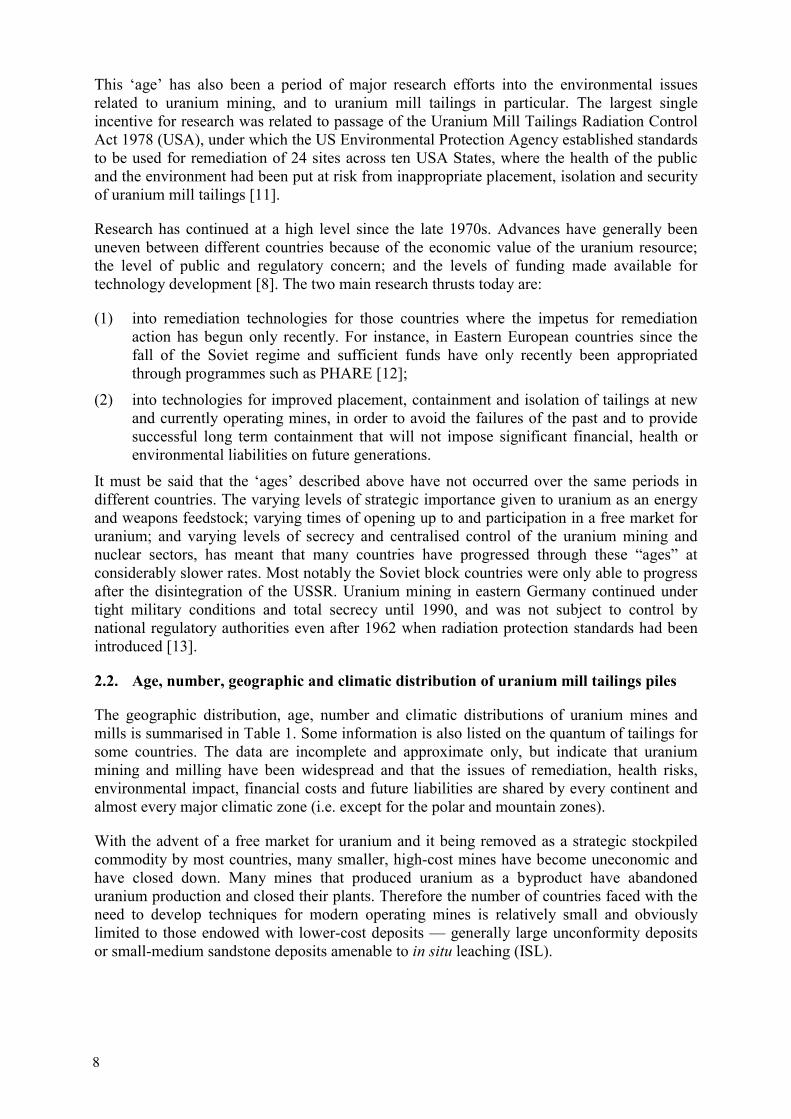
This ‘age’ has also been a period of major research efforts into the environmental issues related to uranium mining, and to uranium mill tailings in particular. The largest single incentive for research was related to passage of the Uranium Mill Tailings Radiation Control Act 1978 (USA), under which the US Environmental Protection Agency established standards to be used for remediation of 24 sites across ten USA States, where the health of the public and the environment had been put at risk from inappropriate placement, isolation and security of uranium mill tailings [11].
Research has continued at a high level since the late 1970s. Advances have generally been uneven between different countries because of the economic value of the uranium resource; the level of public and regulatory concern; and the levels of funding made available for technology development [8]. The two main research thrusts today are:
(1) into remediation technologies for those countries where the impetus for remediation action has begun only recently. For instance, in Eastern European countries since the fall of the Soviet regime and sufficient funds have only recently been appropriated through programmes such as PHARE [12];
(2) into technologies for improved placement, containment and isolation of tailings at new and currently operating mines, in order to avoid the failures of the past and to provide successful long term containment that will not impose significant financial, health or environmental liabilities on future generations.
It must be said that the ‘ages’ described above have not occurred over the same periods in different countries. The varying levels of strategic importance given to uranium as an energy and weapons feedstock; varying times of opening up to and participation in a free market for uranium; and varying levels of secrecy and centralised control of the uranium mining and nuclear sectors, has meant that many countries have progressed through these “ages” at considerably slower rates. Most notably the Soviet block countries were only able to progress after the disintegration of the USSR. Uranium mining in eastern Germany continued under tight military conditions and total secrecy until 1990, and was not subject to control by national regulatory authorities even after 1962 when radiation protection standards had been introduced [13].
2.2. Age, number, geographic and climatic distribution of uranium mill tailings piles
The geographic distribution, age, number and climatic distributions of uranium mines and mills is summarised in Table 1. Some information is also listed on the quantum of tailings for some countries. The data are incomplete and approximate only, but indicate that uranium mining and milling have been widespread and that the issues of remediation, health risks, environmental impact, financial costs and future liabilities are shared by every continent and almost every major climatic zone (i.e. except for the polar and mountain zones).
With the advent of a free market for uranium and it being removed as a strategic stockpiled commodity by most countries, many smaller, high-cost mines have become uneconomic and have closed down. Many mines that produced uranium as a byproduct have abandoned uranium production and closed their plants. Therefore the number of countries faced with the need to develop techniques for modern operating mines is relatively small and obviously limited to those endowed with lower-cost deposits — generally large unconformity deposits or small-medium sandstone deposits amenable to in situ leaching (ISL).
8

Table 2. Age, number and size of closed and operating uranium mines and tailings piles by country and climatic zone, and general status of current activities. Main information sources: [7] [14] [15] [16] [17]
Continent Country U mining since
No. hard-rock mines
No. U mills
Climatic zone Tailings –no. piles
Tailings – volume [106 m3]
Tailings – area[ha]
Country status
AFRICA Gabon 1956 5 2 tropical 7 Mining and milling ceased 1999, rehabili-tation due for completion in 2000
Namibia 1 hot desert Zaire 3 subtropical South Africa 34 3 dry grassland NORTH AMERICA
Canada 1933 24 14 taiga 34 ca. 30 ca. 300 Old small sites mostly rehab’d. Major current producer from 3 mines + 3 mills
United States 1898 3900 < 100 dry grassland, hot desert
> 52 120 Major rehab program (UMTRA) completed 1979-99
SOUTH AMERICA
Argentina Early 1950s
11 9 dry grassland, hot desert
8 Mining and milling ceased, planning for rehabilitation in progress
Brazil 1981 1 1 tropical 1 2.17 86ha Mining/milling ended 1997, restoration pending
AUSTRALASIA
Australia 1930s 25 8 tropical, dry grassland, hot desert
10 48.6 620 Old small sites mostly rehab’d. Major current producer from 2 mines
ASIA China 8 subtropical, dry grassland
India 4 3 subtropical Japan 1957 1 1 temperate 1 0.03 12.5 No mining, mill dismantled 1981 Kazakhstan 1955 19 3 dry grassland 3 209 1733ha Only ISL continues – hard-rock mining
ceased Krgyzstan 4 1 mountain, hot
desert 32 Many mines closed in early 1990s, dumps
unremediated. Radioactive tailings still produced as uneconomic (Th) by-product of Au Ag Pb REE mining
Uzbekistan 4 1 hot desert 1 30.0 600
9

Continent Country U mining since
No. hard-rock mines
No. U mills
Climatic zone Tailings – no. piles
Tailings – volume [106 m3]
Tailings – area[ha]
Country status
EUROPE Bulgaria 20 2 mediterranean 3 18.5 Czech
Republic 1948 13 3 temperate 21 46.8 638 Reduced production matched to national
energy needs, mining expected to cease 2002. Rehab of closed sites underway
Estonia 1 1 taiga 1 8.0 Finland 1958 1 0 (ore
exported)
taiga 1 0.04 No mining since 1961
France 1950s 180 (some very small)
8 temperate 19 47.3 256 Mining and milling stopped, old sites being progressively rehab’d since 1990
Germany 1946 9 4 temperate 15 161 727 Production ceased 1990, major Wismut clean-up in progress
Hungary 1956 1 1 temperate 2 20.4 163 Production ceased 1997, rehab planning in progress
Poland 1 0.114 Portugal 55 1 mediterranean 2 3.5 10 1 mine operating, minor production.
Rehabilitation of old mines since 1990 Romania 10 temperate >3 4.5 37 Production from several sites to end in
near future, rehab planning underway Russia 1950 21 2 dry grassland,
taiga 3 54.1 457 Production continues, old workings
rehab’d, rehab and decommissioning plans for operating plants being reviewed
Slovenia 1 mediterranean 1 0.7 Spain 1959 21 2 mediterranean >3 2.4 25 1 mill operating at 1/3 capacity. Old site
progressively rehabilitated since 1991 and continuing
Sweden 1965 1 1 temperate 1 1 25 Production ceased 1969, site rehabilitated 1990-93, ongoing leachate treatment, monitoring & maintenance
Ukraine 1950s 6 2 dry grassland 3 130 686 Production continues from one mill. Restoration activity started in 1991 has paused owing to economic difficulties
TOTALS 4196 163 186 908 5769
10
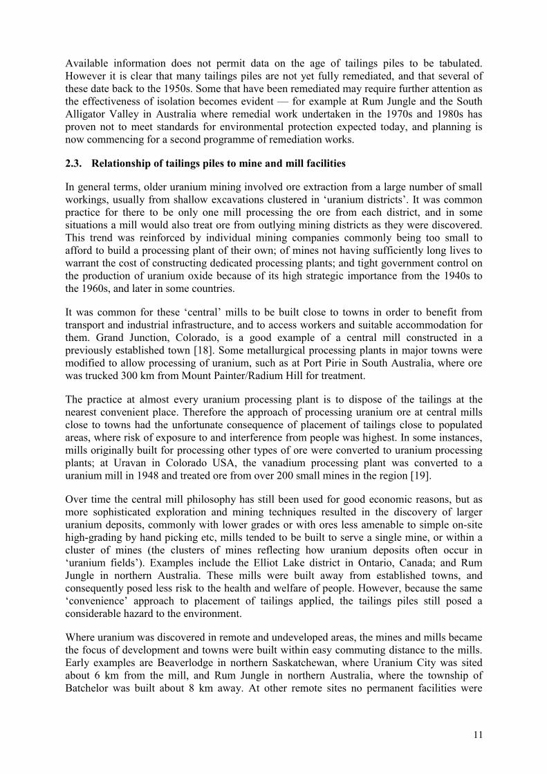
Available information does not permit data on the age of tailings piles to be tabulated. However it is clear that many tailings piles are not yet fully remediated, and that several of these date back to the 1950s. Some that have been remediated may require further attention as the effectiveness of isolation becomes evident — for example at Rum Jungle and the South Alligator Valley in Australia where remedial work undertaken in the 1970s and 1980s has proven not to meet standards for environmental protection expected today, and planning is now commencing for a second programme of remediation works.
2.3. Relationship of tailings piles to mine and mill facilities
In general terms, older uranium mining involved ore extraction from a large number of small workings, usually from shallow excavations clustered in ‘uranium districts’. It was common practice for there to be only one mill processing the ore from each district, and in some situations a mill would also treat ore from outlying mining districts as they were discovered. This trend was reinforced by individual mining companies commonly being too small to afford to build a processing plant of their own; of mines not having sufficiently long lives to warrant the cost of constructing dedicated processing plants; and tight government control on the production of uranium oxide because of its high strategic importance from the 1940s to the 1960s, and later in some countries.
It was common for these ‘central’ mills to be built close to towns in order to benefit from transport and industrial infrastructure, and to access workers and suitable accommodation for them. Grand Junction, Colorado, is a good example of a central mill constructed in a previously established town [18]. Some metallurgical processing plants in major towns were modified to allow processing of uranium, such as at Port Pirie in South Australia, where ore was trucked 300 km from Mount Painter/Radium Hill for treatment.
The practice at almost every uranium processing plant is to dispose of the tailings at the nearest convenient place. Therefore the approach of processing uranium ore at central mills close to towns had the unfortunate consequence of placement of tailings close to populated areas, where risk of exposure to and interference from people was highest. In some instances, mills originally built for processing other types of ore were converted to uranium processing plants; at Uravan in Colorado USA, the vanadium processing plant was converted to a uranium mill in 1948 and treated ore from over 200 small mines in the region [19].
Over time the central mill philosophy has still been used for good economic reasons, but as more sophisticated exploration and mining techniques resulted in the discovery of larger uranium deposits, commonly with lower grades or with ores less amenable to simple on-site high-grading by hand picking etc, mills tended to be built to serve a single mine, or within a cluster of mines (the clusters of mines reflecting how uranium deposits often occur in ‘uranium fields’). Examples include the Elliot Lake district in Ontario, Canada; and Rum Jungle in northern Australia. These mills were built away from established towns, and consequently posed less risk to the health and welfare of people. However, because the same ‘convenience’ approach to placement of tailings applied, the tailings piles still posed a considerable hazard to the environment.
Where uranium was discovered in remote and undeveloped areas, the mines and mills became the focus of development and towns were built within easy commuting distance to the mills. Early examples are Beaverlodge in northern Saskatchewan, where Uranium City was sited about 6 km from the mill, and Rum Jungle in northern Australia, where the township of Batchelor was built about 8 km away. At other remote sites no permanent facilities were
11

constructed so that the local population at potential risk from the tailings piles was at or close to zero (e.g. the Rockhole tailings deposit in the South Alligator Valley of northern Australia [20]). Construction of mills away from population centres significantly reduced the level of impact upon human health relative to mills constructed in or on the fringes of established settlements. However, the same range of approaches was used for siting, containing and depositing the tailings, such that similar impacts upon the environment eventuated wherever tailings piles were made.
In areas where uranium was produced as a by-product on existing mines, e.g. the gold mines of the Witwatersrand, uranium tailings and plant wastes were often mixed with far larger volumes of tailings. Furthermore, in some mines, the tailings contain significant concentrations of uranium and other radionuclides.
2.4. Historical approaches to tailings placements
Past practices for placement of uranium mill tailings are summarised as:
– no effective containment – low embankments – topographic depressions – returned to a mined out pit – within a custom-built ring-dyke or
turkey nest dam – in a valley, usually behind a dam or
dyke – returned to an underground mine – into a deep lake or river.
This list includes effectively all of the options available today for effective containment of tailings, but is also contains options that are now considered unacceptable because of the high probability of containment failure. The main difference between historical placement and that practiced today is that in the past no risk or impact assessments were done and little or no regard was given to selecting the option that would impact least upon human or environmental health. Indeed in the 1950s when many mines and mills began operation, uranium mill tailings were not considered to be problematical, and techniques little different to those used for non-radioactive tailings were employed. The drivers for choosing a disposal site were convenience and cost.
In the following historical examples are given for each of the types of disposal.
2.4.1. No effective containment
In Kyrgyzstan at Mailii Su, 23 separate tailings piles are situated in deep ravines and on river banks falling in to the Mailii Su River and its tributaries; at Kaji-say a tailings pile lies on the banks of a wadi (dry river bed) less than 3 km upstream of a large lake important as a tourist destination [14]. In Slovenia the disposal site near Borst consists of tailings with dams on a sloping area of ground [21]. In Australia, tailings from the Rockhole mine in the South Alligator Valley were placed on a flat area in the floodplain of the South Alligator River and immediately adjacent to the river bank; the river system is now part of the World Heritage listed Kakadu National Park [22]. Some tailings at Grand Junction, Colorado USA were placed on flat ground adjacent to the mill in the centre of the city [22]. Further south at Uravan in Colorado, the tailings were placed on a bench along a canyon wall with no provision for physical stability or containment to prevent cascading to the canyon floor and river below [19].
12

2.4.2. Low embankments
At Rum Jungle and Moline in northern Australia, tailings were deposited behind low bunds constructed on gentle slopes that were prone to over-topping by supernatant water in the tropical wet season and uncontrolled discharge into local creeks and rivers [6].
2.4.3. Topographic depressions
The mill at the Rabbit Lake mine in northern Saskatchewan deposited tailings into a tailings basin constructed by damming a natural depression in the bedrock [23], and some of the tailings generated at Elliot Lake in Ontario were also placed in topographic depressions [24][25]. In Grand Junction Colorado, some tailings were placed in shallow depressions behind river bank levees along the river flats with only minor additional earth works to aid containment.
2.4.4. Valley fill
This approach is more common in mountainous areas owing to the scarcity of flat ground for other forms of construction. In Kyrgyzstan at Ming Kush tailings were deposited in a permanent stream valley and the stream flow diverted around the pile by two bounding canals [14]. At Jaduguda in India, the cyclones sand fraction of the tailings are used as underground backfill, and the slimes are pumped to a natural valley site with decant allowed to flow over an earthen dam [26]. At Nejdek in the Czech Republic tailings were placed behind a dam on the Rolava River, which receives flows of supernatant water [7]. Tailings at the Priargunsky operations near Krasnokomensk in Russia are held in two valley-fill dams [7].
2.4.5. Ring dyke or turkey nest dam
One of the earliest dams of this type was built in 1958 at Grants, New Mexico USA, where tailings from the Kerr-McGee mill were totally surrounded by a high embankment built in several ‘lifts’, with each lift being constructed of the cycloned coarse tailings fraction [22]. This approach was taken owing to the absolute flatness of the landscape and the absence of any natural depressions, embankments or levees. Whilst statistical information on construction methods of tailings impoundments is only fragmentary, it is probable that this method is now a common form of tailings facility construction [7]. It had become a popular technique by the 1970s, for example in France where many tailings storages constructed in this decade are of this type (e.g. Gueugnon, Rophin, Bois Noirs Limouzat, Ecarpiere, Lavaugrasse, Jouac).
2.4.6. Mined out pit
This approach is confined to situations where the mill is in an area of previous extractive mining or quarrying, or where the deposit being mined is amenable to progressive excavation and back-fill – for example where the deposit is made up of a series of ore lenses. At Ranstad in Sweden, tailings were back-filled into worked-out parts of the shallow open-pit [22]. Tailings from the Cellier, Brugeaud, Montmassacrot, Bellezane, Lodeve and St. Pierre du Cantal mines in France are held in old open pits [7]. One of the three impoundments at Ukraine’s Zhovty Vody mill is in an old iron ore open pit [7]. Two old open pits were used to dispose of uranium mill tailings at Seelingstädt in Germany [15]. At Nabarlek in Australia, tailings were pumped directly to the pit from which the uranium ore was extracted, facilitated by the high-grade ore being mined out within a year and stockpiled at the beginning of the
13

project; milling then took place over ten years as the stockpile was depleted [7]. The same was undertaken at Rabbit Lake, Key Lake, and Maclean Lake in Sasketchawan, Canada.
2.4.7. Underground mine back-fill
Some tailings from the Gunnar mill in Saskatchewan, Canada, were returned into the underground workings [7]. It is also considered as an option for the remediation at the Zirovski Mine in Slovenia [21] and some mines in the Ukraine (see Annex XII) and in some cases for the Wismut mines.
2.4.8. Deep lake or river
Tailings disposal from the Port Radium mill in Canada’s Northwest Territories included placement in several small lake basins and also deep-water discharge into Great Bear Lake [7]. Lake disposal was also common in northern Saskatchewan in Canada: most of the tailings from the Gunnar mill were deposited into Mudford Lake about half of the Beaverlodge mill tailings went into Fookes and Marie Lakes [23]. Tailings were also discharged into lakes in some mines operating under the jurisdiction of the former Soviet Union [7].
This list of examples demonstrates that the natural features of the landscape in the vicinity of the mills determined how the tailings were placed. Steep valleys in mountainous areas, lakes in the glacial till-covered Canadian shield and northern Russia, mined-out pits in areas of previous mining activity, and opportune natural depressions were all obvious and convenient features. Where such features were not present, low bunds or ring dyke structures were sometimes constructed where the developers had some concern or forethought for possible health or environmental effects. However these were commonly inadequate in their design to provide service for more than the short term, and commonly failed. In other situations no provisions for containment were made at all, and the tailings were accessible to people and fauna as well as to dispersion through wind, surface water erosion, and seepage to groundwater.
2.5. Classification of uranium mill tailings
The volume of tailings piles varies from several hundred to several tens of millions of cubic metres, depending on the size, nature and duration of the operation. The activity of the tailings depends on the grade of ore mined and varies from less than 1 Bq/g to more than 100 Bq/g. The grain size distribution plays a major role in the physical stability, consolidation and hydraulic properties of the tailings. It is related to the nature of the host rock, the texture of the mineralization and the crushing and grinding processes applied in extraction. A classification based on various geotechnical and phenomenological criteria has been proposed [27] (Fig. 2).
The chemistry of tailings depends mainly on the leaching process (acid or alkaline) and the mineralogy of the ore. Wastes from the mining of sulphidic ores tend to produce acid leachate, which can mobilise radionuclides and other hazardous components of the tailings.
Trace element concentrations in the ore and process chemicals may have a major influence on the tailings chemistry and its total environmental impact.
14

0.6 6.0 60060Liquid Limit
D11D3
Foot traffic
Pickup
Dozers
Haul Trucks
0.03 0.3 3.0
Centrifugal pumpsPositive Displacement pumps
“Raining” ? ?
Beaching ? ?
IntensiveImprovements Conveying End-dumping
“Mobilized” Undrained Shear Strength (kPa)
Critical Bearing Pressure (kPa)
Critical Cap Thickness (m)
Pumping Limits
- hydraulic
- dry land
Capping Method Limits:
Trafficability Limits
Terminology
Reclamation Methods
Note: “limits” refers to lower bound operational strength
FLUIDTAILINGS
WATERCAPPED
VERYSOFT
TAILINGSSOFT
TAILINGSHARD
TAILINGS
SOFT GROUNDSTRATEGIES
NORMALTERRESTRIALRECLAMATION
0.01 0.1 1 10 100 1000
Fig. 2. Proposed classification of tailings for remediation purposes [27].
2.6. Inappropriate uses of uranium mill tailings
The coarse, sandy nature of some mill tailings makes them an attractive resource for re-use as a building material, mainly as sand for concrete making. Re-use was a feature in areas where tailings piles were in or close to urban centres and where controls on access and removal were low or absent. Perhaps the most extensive re-use was in Grand Junction, Colorado, where tailings were used as sand for concrete manufacture, mortar, backfill around foundations, and as fill under pavements and streets etc [18] [28]. Over 4050 properties contaminated by uranium tailings have been cleaned up in the ‘UMTRA Vicinity Property Program’, with over 1.65 million cubic metres of contaminated material removed from, around or beneath civic buildings, private homes, footpaths, drainage dykes, industrial sites, police stations, jail, sewer system and railway line beds [29].
Similar use of tailings was made in other uranium milling districts, including the Saxony and Thuringia areas of Germany [22] [30] Lower Silesia in Poland (see Annex X) and Port Hope in Ontario, Canada [25]. Tailings that flowed into the local river after failure of the containment structure in 1962 were recovered by the local people of Ak-Tuz in Kyrgyzstan and used as a building material [14].
15

3. ENVIRONMENTAL IMPACTS
3.1. Events that have led to environmental impacts
The types of events that have led to environmental impacts can be broadly categorised into chronic and acute failure [31]. Acute failures involve sudden physical failure of the containment structure, and are listed in Table 3.
Table 3. Examples of tailings (including uranium) dam failures, data from [32] [44] [45]
Date Location Parent company
Type of Incident Release Impacts
(1994) Zirovski vrh, Slovenia
Rudnik Zirovski vrh, Gorenja vas
ongoing slippage of the slope (7 million t) with the “Borst” tailings deposit (600,000 t) on the top, at velocity of 0.3 m per year
n/a n/a
1994, Feb. 22 Harmony, Merriespruit, South Africa
Harmony Gold Mines
Dam wall breach following heavy rain
600,000 m3 tailings travelled 4 km downstream, 17 people killed, extensive damage to residential township
1994, Feb. 14 Olympic Dam,Roxby Downs, South Australia
WMC Ltd. leakage of tailings dam during 2 years or more; for details see SEA-US, NIC
release of up to 5 million m3 of contaminated water into subsoil
n/a
1979, Jul. 16 Church Rock, New Mexico, USA
United Nuclear
dam wall breach, due to differential foundation settlement
370,000 m3 of radioactive water, 1,000 tonnes of contaminated sediment
Contamination of Rio Puerco sediments up to 110 km downstream
1979, Mar. 1 Union Carbide, Uravan, Colorado, USA
Union Carbide
two slope slides, due to snow smelt and internal seepage
n/a n/a
1977, Feb. 1 Homestake, Milan, New Mexico, USA
Homestake Mining Company
dam failure, due to rupture of plugged slurry pipeline
30,000 m3 no impacts outside the mine site
1977 Western Nuclear, Jeffrey City, Wyoming, USA
Western Nuclear
dam failure, due to melting of snow
40 m3 of tailings and 2.3 million gallons of liquid
“no offsite contamination”
1976, Apr. 1 Kerr-McGee, Church Rock, New Mexico, USA
Kerr-McGee dam failure, due to differential settlement of foundation soils
‘minor quantity’ n/a
1971, Mar. 23 Western Nuclear, Jeffrey City, Wyoming, USA
Western Nuclear
dam failure, due to break in tailings discharge line
n/a “no offsite contamination occurred”
1967, Jul. 2 Climax, Grand Junction, Colorado, USA
Climax dam failure, due to unreported causes
12,000 m3 Effluent release into an adjacent river
1963, Jun. 16 Riverton, Wyoming, USA
Susquehanna Western Inc.
The dam was intentionally breached and a 2-ft depth of effluent was released to prevent uncontrolled release of the impoundment contents during heavy rain
n/a n/a
1962, Jun. 11 Mines Development, Edgemont, South Dakota, USA
? dam failure, due to unreported causes
100 m3 Tailings released reached a creek and some were carried 25 miles to a reservoir downstream
1961, Dec. 6 Union Carbide, Maybell, Colorado, USA
Union Carbide
dam failure from unreported causes
280 m3 Effluent released did not reach any stream
1960 Gunnar mine, Beaverlodge area, Saskatchewan, Canada
Gunnar Mines Ltd.
dam failure n/a Tailings release into Lake Athabasca, creating Langley Bay tailings delta
Note: n/a – no information available
16

Causes for acute failure in uranium tailings dams are no different from those at other mill tailings dams. The causes, earthquake-induced instability and failure owing to cracking or liquefaction; physical weakness of the embankment leading to breaching; erosion from heavy rain or adjacent waterway leading to thinning of the wall or overtopping by decant water; cracking induced by settlement; piping; lateral instability (movement) of the wall caused by insufficient mass or lubrication by saturated weak foundations; slumping of material into the containment, causing overtopping and/or erosion of the wall or its physical destruction; and spillway collapse caused by heavy overflow of decant or slurry after severe rainfall [33].
0
25
50
Ove
rtop
ping
Slop
e St
abili
ty
Eart
hqua
ke
Foun
datio
n
Seep
age
Stru
ctur
al
Eros
ion
Min
eSu
bsid
ence
Unk
now
n
Num
ber o
f Inc
iden
ts
Active DamsInactive Dams
Fig.3. Tailings dam incidents (a total of 199) classified by cause of failure and active/inactive facility [34].
The various causes of tailings dam incidents (ie acute events, and chronic events indicating performance inconsistent with design at all tailings dams including non-uranium tailings facilities) are tabulated for 199 incidents in Fig.3. At inactive dams the main causes are earthquake and over-topping; for active dames the leading causes are slope instability and seepage, followed by earthquake, over-topping, foundation conditions (including mine subsidence), and structural [34]. About 90% of the documented incidents were associated with active impoundments where the dams contained surface water as decant liquor or flood water, indicating that tailings pore water pressures and water management practices encountered during operation of the facility are major risk factors, which become much less significant after closure (Fig.4). The data also suggest that dams built by the upstream construction technique (see Section 6.3) are prone to the most failures, but this also be due to the fact that the majority of tailings dams in the data set are of this type.
A review of the literature suggests that tailings containments have been subject to most of these types of failure, although the details of the cause of failure are rarely reported. Examples — not necessarily only uranium tailings — include Church Rock USA 1979 [36], Moline Australia between 1973 and 1980 [22] [37], Rum Jungle, Australia (various times) [22]; Schneckenstein in Germany [38], Merriespruit in South Africa (Fig.5) [39] [40]. Notably,
17

0 25 50 75 100
Upstream
Water Retention
Downstream
Centreline
Unknown
Number of Incidents
Inactive DamsActive Dams
Fig.4. A selection of 199 tailings dams incidents classified by embankment construction type and as active/inactive facilities [34].
Fig.5. The Merriespruit (South Africa) tailings dam failure in 1994 [35].
whilst most of these dams and embankments were not purpose-designed or built, existing simply of waste rock or local soil or even tailings being roughly bulldozed to form a bank, the Church Rock containment was hailed in its day as the most carefully engineered tailings dam in the State of New Mexico. However, engineering assessment after the failure pointed to multiple failures in design, construction, and management. Differential settling was caused by construction over inhomogeneous foundations of solid bedrock and weak soils and cracking was visible for two years before the actual failure. Furthermore, the drain zone had not been constructed according the approved plans, no tailings beach had been formed against the wall as recommended, and the level of water was 0.6m higher than design limits at the time of failure [36].
18

There are many forms of chronic failure. These include:
Dispersal of radioactive dust: tailings surfaces allowed to dry out, followed by wind-blown distribution of dust. This is reported as a problem in almost every area of historic tailings storage, e.g. Durango in Colorado [22], Wismut operations Germany [30], West Mecsek Hungary [41], Bukhovo Bulgaria [36], Kyrgyzstan [14], Rum Jungle Australia [22], Ulba, Kazakhstan (see Annex VII);
Erosion of tailings from outer surfaces of the containment, e.g. Rum Jungle Australia [22], Wismut operations Germany [30];
Seepage through the floor and/or walls of the containment – many early containments were constructed with no seal or seepage collection system in the base (e.g. Mecsek in Hungary [41], Schneckenstein Germany [38], Kyrgyzstan [30]. On some of the Far West Rand mines in South Africa, tailings dams were sited on karst features in dolomite to promote drainage. At Anhua in northern China seepage from the tailings dam resulted in significant uranium and cadmium contamination of a lake used for agricultural irrigation [42]. In Estonia seepage from the tailings pile near the coastline has resulted in measurable contamination in the Baltic Sea up to 300m from shore [36];
Effluent discharge as decant allowed to drain or overflow from the containment directly or indirectly into natural waterways, for example at Jaduguda in India [22] [26] and several Wismut operations in Germany [38]. At Elliot Lake in Canada, effluent discharge resulted in significant radiological contamination and acidification of the 300 km2 Quirke Lake [24].
Both acute and chronic events are commonly associated with non-radiological impacts related to heavy metals and other toxic compounds in the tailings, pore water, and decant water. Of particular concern is the generation of acid conditions from tailings derived from sulfidic ores. In the past un-neutralised tailings with acid-producing potential were deposited. These tend to exacerbate the probability of contamination because of the solubility (and hence greater mobility) of many metals under acidic conditions. It may also affect the bioavailability of toxic metals and compounds [43]. The neutralization of tailings prior to deposition, when required, has become common practice in more recent times. Therefore the level of impact caused by tailings and tailings waters released through containment failure may vary significantly due to the chemical nature of the material as well as the sensitivity and condition of the receiving environment.
3.2. Impacts on human health
Sudden failure of any large structure may cause death through drowning, crushing or suffocation, and the larger uranium mill tailings containments are the same as tailings from other types of mines or from water containment dams in that regard. Landslides involving precariously placed uranium mill tailings at Mayluu-Suu in Kyrgyzstan over a 30 year period, killed people and destroyed buildings [14]. However, the failure of uranium tailings containments does not feature highly on the list of dam failures to have caused death or major destruction [32] [46], perhaps because dams at uranium mines are a small proportion compared to the total number of mine dams. They are also are generally smaller than the very large dams at many large scale. Low tonnage, gold and base metal mines developed around the world over the last 20 years.
Although other types of mill tailings may also contain radionuclides, the particular human health risk that is associated with uranium mill tailings is the risk from radioactivity. In turn, uranium mill tailings may also pose risks associated with their inventory of heavy metals and
19

other chemical elements, such as arsenic. It is not possible to determine the actual risk or the level of harm caused by tailings distinct from other causes, because people affected by radiation in uranium mining districts are potentially exposed to radiation doses from mining, milling, transport of radioactive materials, radioactive dust and contaminated water and foodstuffs, at it is not practicable to distinguish between this mixture of point and diffuse sources.
Tailings in themselves may pose a significant proportion of the health hazard because of the manner in which they are commonly disposed of. The disposal at the surface over relatively large areas allows significant flux of radioactive gasses and interaction with surface water. In many historic uranium mining areas both have constituted a pathway from the immediate surrounds of the mine site and impacted upon the general public. However, the information on the relative and absolute impact can be unclear or confusing – for example, an analysis of the downstream impacts from the Church Rock tailings spill (New Mexico USA) in 1979 concluded that “there were no demonstrable health effects” and that groundwater contamination was no greater that pre-spill conditions [47]. However, it is probable that the ‘pre-spill conditions’ against which contaminated levels were compared were themselves elevated as a consequence of long term seepage from the mining operations [32], indicating that long term assessment of effects may be poorly founded.
The long half-life of radiation from uranium tailings and the demonstrated risks association with them have given rise to levels of high concern in the general public and in government – in some places exacerbated by the high levels of secrecy and lack of data on health impacts such as in the Saxony-Anhalt/Saxony/Thuringia areas of Germany [6]. Here, people in the ‘immediate vicinity’ of (unremediated) tailings from the Wismut operation were subject to additional doses of 1-2 mSv/year and in special cases up to 6 mSv/year [15].
Perhaps the most direct implication of tailings as a radiation source sufficient to cause human health impacts relates to the re-use of tailings for building materials. Whilst this has happened in many places around the world (see Section 2.6), it is best documented in Grand Junction, Colorado, in the Unites States of America. It became known in the mid-1970s that leukaemia rates in the county including Grand Junction city were twice the average for the State. This fact, and the concern it caused, was the driver for the development of state legislation for radiation control and protection measures, which led to the development of the Uranium Mill Tailings Remediation Control Act 1978 (UMTRCA Act) [18].
The body of research which indicated that direct impacts on human health were resulting from exposure to uranium mill tailings gradually grew, with the realization that radon concentration in houses built with mortar sand derived from uranium tailings, or over tailings-derived fill etc. could reach dangerous levels (e.g. 200 000 Bq/m3 at Schneeberg in Germany [30] [36], radon and dust derived from tailings were calculated to result in between 0.3 and 1.0 death per 2600 residents of Eleshnitza in Bulgaria, and radium concentrations were found in cereals being grown in tailings-contaminated soils [48].
These concerns have resulted in a large body of research being undertaken on the mechanisms of transfer of radiological dose to humans via a variety of pathways, and the development of models to determine biological as well as non-biological pathways (see for example BIOMOVS [49]). Uranium mill tailings are one of a number of potential sources for uptake, e.g. [50].
An evaluation of the completed US American UMTRA programme calculated that 1289 lives will be saved over 100 years (using a linear model with no threshold values) as a consequence
20

of removal of uranium mill tailings and placement in purpose-designed containment structures removed from populated areas [51]. The UMTRA programme serves to demonstrate that uranium mill tailings were identified in the USA as a significant health hazard. Whilst this assessment may overstate the numbers of lives saved because of the methodology used for the calculations, it demonstrates that the risk is sufficient to warrant major expenditure to clean up old sites where tailings have been disposed of inappropriately, and to develop regulations to ensure that similar hazards do not eventuate from modern uranium mining and milling activities.
3.3. Potential radiological impacts upon the natural environment
There are many articles in the literature that purport to describe impacts on the natural environment from uranium mining in general, and the placement/disposal and management/mismanagement of mill tailings in particular. However, the description of environmental impact that most of these articles present is limited to a qualitative description of impact in terms of contaminated soil, surface waters, groundwaters, lake sediments etc (e.g. [14] [15] [33] [36] [37] [42] [52]), any quantitative description is usually given in terms of the area/volumes affected and concentrations of radioactive elements (e.g. [14] [15] [36]), or activity levels and doses (e.g. [17] [53]. A body of literature exists on the contamination of environmental media directly linked to consumption and therefore potential uptake of radionuclides by man: principally soils (e.g. [14] [53]), and water, e.g. [54]. In contrast, there are relatively few articles that set out to quantify the level of harm to the biosphere caused by uranium mill tailings.
Research into the biological impacts from the nuclear fuel cycle is a relatively new science, and is strongly biased towards research on the risks, hazards and impacts to humans from the fuel fabrication, power generation and fuel reprocessing/disposal parts of the cycle. However, interest in research into the biological impacts from the uranium production part of the nuclear fuel cycle has grown from:
A realization that fisheries in the vicinity of some uranium mines were deteriorating, e.g. [24] [25] [55] [56];
A realization that radionuclides could be taken up by plants, thereby posing a potential risk to vegetation as well as animals higher in the food chain including humans, e.g. [14] [57] [58];
A realization that radionuclides could be taken up by animals, thereby posing a potential risk to the health of individuals, communities and ecosystems as well as animals higher in the food chain including humans, e.g. [47] [53] [59];
Documentation on the concentration of radionuclides in bottom sediments and their long term availability to bottom feeders and potential for multiple cycling through the aquatic food chain over the long term, e.g. [60];
Development of transfer pathway models for the transfer of radiological dose through the food chain, e.g. [49];
Concern that tangible impacts on human health from radioactive contamination associated with uranium mines and tailings piles may also be having significant impacts on the environment [11?]; and
21

Questions over the validity of ICRP’s 1977 statement [61] that: “although the principal objective of radiation protection is the achievement and maintenance of appropriately safe conditions for activities involving human exposure, the level of safety required for the protection of all human individuals is thought likely to be adequate to protect other species. The Commission believes that if man is adequately protected then other living things are also likely to be sufficiently protected”.
At the time the available evidence suggested that humans were indeed the most radio-sensitive species. Some recent discussion includes suggestions that significant evidence of environmental damage from ‘controlled practices’ is hard to find [62], and that concerns over impacts from uranium mining, particularly in remote areas such as in Canada, have been over-stated [63]. However, since the late 1970s there has been a general increase in concern for the environment, presumably due to evidence that the actions of humans are causing visible and significant environmental changes, for example the effects of gaseous effluents on sensitive ecosystems through acid rain and on the ozone layer and the pollution of rivers as a result of pesticide application to farm land. Furthermore, close attention s now being paid to the larger implications of harm being caused to elements of particular ecosystems with consequent impacts on biodiversity. It is perhaps for these reasons that the issue of environmental protection in the context of ionising radiation is being addressed in many countries [62]. A recent IAEA review of practices for close-out of uranium mines and mills observed that:
“In recent years more attention has been directed to the impacts that the nuclear fuel cycle may have on the environment. When environmental media (soils, surface and ground waters, and air) have increased contaminant levels, biota may also take up and accumulate contaminants. Such uptake may pose a threat to ecosystem vitality in the shorter term and to the biological community structure in the longer term. As humans ultimately depend on the environmental media of soil, water and air for survival, and also occupy the top of the food chain, there is an inescapable link between human health and safety, and the health of the environment” [31].
This concern is demonstrated through a series of conferences addressing ‘Protection of the natural environment from ionising radiation’ (Stockholm, May 1996; Ottawa, May 1999; Darwin, July 2002). Several papers in these conferences document changes in biota directly attributable to ionising radiation, e.g. lower fecundity, more genetic diversity and DNA strand breaks in mosquito fish in ponds near the Oak Ridge National Laboratory in Tennessee USA [64]. Whilst most papers are related to effects of ionising radiation from nuclear power plants etc., some papers are reporting investigations into areas contaminated by uranium mining and milling. In that, meaningful comparisons can be made with data such as those prepared by the US National Council on Radiation Protection and Measurements on the effects of ionising radiation on aquatic organisms, which relate to dose levels mostly much higher than those encountered in situations at mine, mill and tailings pile sites [65]. Notably, one paper presented at the Darwin conference in July 2002 assesses the impact of radionuclide releases from Canadian nuclear facilities on non-human biota. It concludes that whilst releases from uranium refineries and conversion facilities, power reactors and associated waste management facilities and research reactors are not entering the environment in concentrations likely to have a harmful effect, the same is not true for releases of radionuclides from uranium mines and mills and waste management areas. Releases from mines, mills and waste facilities are assessed as to be in sufficient quantities or concentrations or conditions that have or may have a harmful effect on the environment [66].
22

3.4. Toxic and hazardous compounds in tailings and their potential impacts
The impacts on the environment from uranium mill tailings are not all related to the radionuclide content alone. The presence of other contaminants can exacerbate the availability of the radionuclides to the environment, and in some cases the other contaminants have direct harmful effects in themselves. In this regard, the potential for uranium mill tailings to cause environmental harm is little different from other forms of mill tailings, and the resultant impacts may be very similar. Indeed it is not adequate to consider the radiological impacts from uranium mill tailings that relate only to the effects of ionising radiation.
The other effects may include:
the chemical toxicity of the radionuclides, including uranium; the chemical toxicity of heavy metals and metallic compounds; the chemical toxicity of non-metallic minerals and compounds in the
ore or introduced during processing (e.g. sulfuric acid, kerosene); acidity, resulting from sulfidic (ore) minerals or acid introduced during milling; turbidity; salinity.
The types of non-radiological contaminants that may cause harm are dependent of the nature of the mineralization in the ore body, including the gangue mineralogy, and the processing technique used in the mill; choice between acid and alkali leach, and whether to neutralise the tailings prior to deposition, has marked effects on the levels of contaminant concentrations in the slurry. It also affects the bioavailability of many compounds.
Some historic impacts have been improperly ascribed to uranium, such as at Rum Jungle in Australia, where 15 km of river and riparian ecosystem downstream of the mine and tailings pile was killed following discharges of copper-rich acidic drainage; effluent from the tailings is estimated to have contributed less than 5% of the total copper load, and uranium is not considered to contributed to the impact to any significant degree [7][22]. Arsenic is a significant constituent of Schlema-type ores in the Ronneburg district of Germany, and contributes significantly to environmental impacts, particularly ground water quality [15]. Cadmium has contaminated farmland and polluted a lake critical for agricultural irrigation near the Xiushui mine in China [42].
Elevated acidity plays a major role in increasing the mobility of metals in aqueous solution, including uranium as well as copper, arsenic, cadmium and other metals. Impacts on vegetation in the Uranium City district of northern Saskatchewan are a result of tailings salinity, acidity, and low fertility [25]. Acid drainage has led to serious contamination of ground water systems in several countries, notably Germany [15] and USA [54] (note that severe ground water contamination in the Czech Republic relates to ISL mining, and no mill tailings are implicated).
As reported in a recent review on mine and mill close-out procedures by the IAEA:
“Acid drainage … can be a prime environmental concern. Low pH waters may dissolve minerals containing radioactive elements and heavy metals. Acidity combined with deposited salts and heavy metals can prevent plant growth. In addition, downstream surface water bodies may become contaminated and affect the health of the ecosystem. Stream banks may become destabilised as the vigour of vegetation supporting the banks
23

is decreased. Dissolved uranium and daughter products can reach levels in water leaching from tailings and uranium waste rock piles which pose a direct chemical toxicity threat to ecosystems.” [31].
The potential for impacts from non-radiogenic contaminants has been investigated in modern Environmental Impact Studies for uranium mine development proposals. Perhaps the first was for the Ranger mine in Australia [10], where loads, concentrations and possible effects of base metals and sulfates on the environment were assessed prior to approval for mine development.
It is interesting to note that the same principle espoused by ICRP concerning man as a suitable indicator species for environmental health does not apply to non-radiological contaminants, because in the aquatic environment some elements are more toxic to aquatic organisms than to man [43]. The effects of heavy metal pollution are complex and strongly dependent on local geographic and climatic factors, the mix of chemical constituents present, and on the nature of the affected organisms. Effects can be lethal or non-lethal. Chronic sub-lethal poisoning can affect growth, reproduction, behavioural patterns, and result in lower resistance to disease, as well as causing the organism to have body concentrations of elements above standards permitted for consumption. In some instances the non-radiological hazards have a much larger effect than the radiological pollutants [53]. Non-radiological components are reported as more limiting on operations at the Ranger mine in Australia than for the radiological contaminants [67].
4. REMEDIATION PROGRAMMES TO REDUCE HAZARDS FROM HISTORICAL URANIUM MILL TAILINGS
4.1. Driving forces for remedial work
The fundamental reason to remediate tailings piles is to reduce the level of hazards and thus lessen the risk of significant impacts upon human health and the environment, or to reduce ongoing levels of impact where effects are already apparent. Whilst the objective may be altruistic, that is the work is undertaken because of a concern for human and environmental well-being, the objective typically is also based upon concerns about the potential cost of not undertaking remedial works. These costs may be in the form of:
Compensation payments, where a case is made that inadequate or improper measures were taken to safeguard people or the environment;
Lost productivity from contaminated and quarantined land or fisheries; Development costs for constructing water wells or sophisticated water treatment plant to
replace water previously supplied from now contaminated surface and ground water resources;
The larger financial consequences from greater areas of contaminated land and water resources and continued contamination or air sheds should the remedial work not be undertaken.
Regulatory and legal frameworks pose significant potential (financial) risk to organizations holding liabilities in the form of current or past mine, mill and waste storage facilities. Increased knowledge of the harm caused by and the potential risks associated with such facilities, more open arrangements to access information and to challenge responsible agencies, greater accountability required of government and private enterprises, and increased
24

public concern, combine to provide powerful incentives for reducing current and potential future liabilities through design and execution of remediation works.
4.2. Remedial work undertaken
The incentive for remedial work to be undertaken by the private sector is to comply with regulatory requirements. Examples of remediation of historic sites by the private sector are limited. Many of the mines concerned, which began operations in the 1940-1950s, were operated by government agencies or were subject to tight government control through to their closure. A few continued operating through to the 1970s and later, when regulations requiring remediation of tailings piles were in place in some Western countries. Therefore upon closure the private operator was compelled to conduct remedial works consistent with the regulations of the day. The number of private sector entities, where liabilities to remediate historic uranium mill sites could be identified, was however further reduced owing to many going out of business during the years of low uranium prices in the 1980s. Examples of remediation of historic sites by the private sector include the Beaverlodge area in Saskatchewan, and Mary Kathleen in Australia.
The Eldorado Beaverlodge operation was shut down in 1982 after 29 years. Decommissioning objectives were set by a panel of regulators in radiation protection, safety and environment. Physical decommissioning at Beaverlodge, which included a number of satellite mines, was done in three years. Monitoring continues to this day and is undertaken by government agencies. When stable conditions are evident, the company will apply to relinquish the leases and turn the property over to the government [63].
At the Mary Kathleen mine in Queensland Australia, mining and milling took place in two periods between 1954 and 1982. By the time operations ceased, regulations requiring remediation of the tailings pile had come into force, and the operator was required to design and complete remedial works consistent with these requirements [68].
Several governments around the world in the last twenty years have implemented major remedial works. The timing and type of programme has been influenced by several different factors. These include access to information on health and environmental effects, changes in government agencies’ attitudes towards making information available to the public, access to sufficient funds, and the type and extent of operations, and their impacts on the environment. Funding is not necessecarily an impediment in Western countries, provided that the problems translate into political debate and pressure. However, some other countries have been unable to implement remediation owing to lack of funding or political willingness. The breakdown of the Soviet Union made public discussion on impacts from uranium mining and milling possible for the first time in many countries. German unification led to sufficient funding for dealing with the impacts from uranium mining and milling in the former GDR. Plans for extension of the European Union to include Central and Eastern European (CEE) countries led to development of a funding scheme for remediation planning and execution in those countries under the PHARE programme [69]. Similar assisstance is being given be the EU to former Soviet Republics under the TACIS (Technical Assisstance to the Commonwealth of Indipendent States) programme. Some examples of government remediation programmes are given in the following subsection.
25

4.3. Examples from the USA
A suggested link between leukaemia rates and uranium mill tailings in Grand Junction, Colorado was the driver for development of legislation for the Uranium Mill Tailings Remediation Programme (UMTRA) [18]. The UMTRA programme in the USA focussed specifically on uranium tailings piles accumulated at 22 sites mainly in the central western states [70]. In many places tailings had been placed in unbounded or poorly bounded piles on level to gently sloping ground. Several piles were within city limits and along or close to river banks. Dust dispersion of the tailings, and re-use by the community as construction sand and fill, gave rise to significant health risks. The programme resulted in tailings being moved from the remnant piles, and reclaimed from thousands of urban sites, for relocation in purpose-designed and built repositories. The repositories generally consisted of lined storage cells with rock-armoured embankments designed to last at least 1000 years. Capping to minimise the risk of exposure of the tailings and reduce radon flux was placed on top. The containment designs were based on extensive research funded for the purpose by the US Government.
4.4. Examples from France
Milling residues were stored at 22 locations across France, and their remediation is part of a programme to rehabilitate mines, mills and waste storages in accordance with regulations under the Mining Code, Registered Facilities for Environmental Protection, and general regulations dealing with water, air, water, noise and landscape protection [71]. Except for the Forez site (where residues are stored under water), the tailings are above ground level, covered with clean waste rock from the site to provide mechanical protection, resist erosion and intrusion, and to reduce radiological flux and exposure. Drainage works are included, to minimise the volume and concentration of contaminated surface water.
4.5. Examples from Germany
Remediation of the WISMUT sites in the states of Saxony and Thuringia entails a range of stabilization measures, such as mine flooding, reshaping and covering of waste rock dumps, pit backfilling and in situ consolidation of the tailings ponds [72]. Owing to the climate, intensive land use and regulatory conditions, the water pathway is most important in the evaluation of remediation options. The goal is not to stop all releases of contaminants, but to reduce loads to levels that fall within the natural assimilative capacity of the surrounding environment.
4.6. Examples form the Czech Republic
Uranium mining and milling are controlled by the state in the Czech Republic. Due to declining needs, increases in production cost, and low world market prices a step-wise reduction of uranium production was decided at the end of the 1980s. The state-owned enterprise DIAMO is now responsible for a large scale closure programme, including technical, social, and environmental aspects. The first decommissioning and remediation works of exhausted mines were undertaken in the 1950s, but these works are sometimes considered inadequate, resulting in ‘legacy sites’. As part of the policy of continuing improvement of the environment, the government is funding the remediation of such ‘legacy sites’ [206]. Between 1993 and 1997 an inventory of these ‘legacy sites’ was drawn up. A respective remediation project was initiated in 1998, and by its completion in 2007 is estimated to have cost 232.3 M CZK (8.3 M USD). Overall, the DIAMO remedial activities concern conventional as well as in situ leaching sites, tailings ponds, and long term water treatment facilities. Environmental activities will have to continue until about 2040 and are
26

estimated to cost above 60.0 bill. CZK (2.2 bill. USD). The predominant part (> 90%) of these activities is being funded through the state budget of the Czech Republic.
4.7. Examples from Australia
The Rum Jungle mining area was operated by a private company under contract to the government and remained unrehabilitated after milling ceased in 1972. A small clean up programme in 1977 dealt mainly with aesthetic matters, but failed to prevent occasional breaches of the dam and continued releases of tailings and liquor to the Finniss River. The government funded a remediation programme aimed at reducing hazards in 1985–86, in which tailings and contaminated soil were placed in one of the open pits without any preparation. The tailings were covered with a geomembrane and a 1 m rock blanket, then alternating layers of contaminated subsoil and copper heap leach material. The area was then covered with topsoil and revegetated, and drainage diversions installed [22]. Hazard reduction works were also undertaken in the South Alligator region, where tailings were removed for reprocessing for gold, and the tailings pad ripped and revegetated.
Concerns over the continued hazards posed in these areas — mainly from open pits and waste rock piles, and requests from indigenous land owners for improved access and use — has lead to funds being provided for studies into performance of the existing remedial works and options for improvement. The tailings areas may be further remediated as part of this programme.
4.8. Evaluation of the remedial works at historic tailings piles
Many remediation programmes of historical tailings piles are not yet complete, or have not been completed long enough to enable meaningful assessments of their effectiveness to be made. A few qualitative assessments are available for some sites, and high level assessments of cost and effectiveness (in terms of lives saved) have been made.
At Rum Jungle in Australia, the post 1982–86 remediation programme monitoring regime indicates that aquatic life has returned to the Finniss River in the 15 km stretch downstream of the tailings pile, which had been killed as a result of copper and uranium contamination. Results from the groundwater monitoring programme suggest that it will take another 15 years before contaminant concentrations leaving the waste heaps drop significantly [7]. However, the level of environmental protection afforded generally by the 1980s remediation works is considered inadequate by today’s standards, and funding has recently been provided by government for planning further remediation work. One aspect requiring attention will be landform design and capping design to reduce the impacts of natural erosive and vegetation processes. The present design requires annual removal of vegetation to avoid capping degradation through root penetration. Clearly this high-maintenance approach is not consistent with objectives for long term stability and reliable stewardship.
Monitoring at Port Pirie in South Australia, where tailings were covered by a 1.5 m layer of zinc slag, indicates that the level of dust generation has been reduced very significantly, and that radon emanation has dropped to below limits recommended by the USEPA for rehabilitated uranium tailings piles [7].
Design of containments built to accommodate tailings relocated by the UMTRA Programmein USA was initially based on steady state equilibrium conditions with covers constructed to limit infiltration into the pile to no greater quantity than seepage rates out of it. However, revised water quality standards required more emphasis on limiting infiltration in order to
27

avoid or minimise groundwater contamination. Other considerations requiring revision of early design concepts and standards were redesign of covers that beneficially exploit ecological changes on and in the cover over time, instead of concentrating solely on physical design parameters that are liable to degrade over time as a consequence of natural erosional, climatic and vegetative processes (see Annex XI).
Attempts have been made to evaluate the effectiveness of remedial work done to date in terms of expected environmental impacts and conditions arising from closed out uranium mine and mill facilities by relative cost and calculated lives saved. An attempt in 1997 to collate such information for the medium to long term was of very limited success [31]: only eight countries responded to this survey question. The information provided was quite different from country to country, and no comparisons or overall conclusions were possible.
Relative costs of remediation of mines, mills and ancillary facilities including tailings piles are reported for individual countries or remedial programmes in various articles, and information has been recently tabulated for a wide range of types of mine and mill and ancillary facilities around the world (Tables 2,3,4 in [7]). The tabulated information does not discriminate costs of tailings remediation from other operational components, but it does indicate which remedial programmes included tailings piles as part of the works conducted. These comprise sites in eight countries (Australia, Canada, Czech Republic, France, Germany, Spain, Sweden, and the USA). The discussion points out that a comparison based on aggregated cost figures would not be objective, because the scope and extent of works will vary considerably for several reasons, even for similar sites and projects. Observations made on the data compilation for mines and mills are equally valid for tailings piles. The costs vary greatly as a factor of the amount of planning and preparation done for remediation and closure during the operational phase, local climate, condition of the tailings pile, degree and area of contamination, population density in the area, land use, labour costs, standards and objectives for remediation, etc. The single undisputable conclusion is that the costs of remediation are very significant, and place a significant budgetary burden on governments.
For this reason an assessment of the effectiveness of remediation in terms of benefits to society is warranted. A good example is the assessment of lives saved as a result of reduced public doses related to removal of tailings in the UMTRA programme [51] [73]. Whilst the basis for calculation may be subject to discussion, this sort of analysis presents information of a type readily understood by government officials and decision makers.
5. PRESENT DAY PRACTICES
5.1. Objectives
Practices for the placement and disposal of uranium mill tailings have evolved to where they are today because of several factors:
An appreciation of the extent of the impacts caused by historic practices and their costs in human safety, social, environmental and budgetary terms;
The large body of information generated from monitoring and research on the types of impacts and how they occur;
Better understanding of environmental systems and the sensitivity at the ecosystem and individual level;
28

Development of regulations and standards prescribing limits on the types, volumes and concentrations of contaminants;
Development of guidelines on design, construction, management and performance of tailings dams etc.;
Increasing public concern on the safety of tailings impoundments and improved organi-zation by NGOs on the topic, as well as increasing levels of expertise available to them;
The efforts by mining companies, in most countries, towards best practice, regular and more open environmental reporting, and a sense of environmental responsibility as a response to expectations from all stakeholders of improved accountability.
The need to include conceptual decommissioning plans in environmental impact studies and mine plans.
Adoption of new practices, and achieving conformity with tighter performance requirements, is much easier for new operations. Conversely, achievement of these new requirements is much harder to ‘retrofit’ to older mines. Remediation of an old mine, where no provision had been made for appropriate stabilization of tailings, will be difficult. The task is likely to be more costly, to take more time, and to result in a poorer outcome than if appropriate planning had been done at the outset.
5.2. Standards for radiological and environmental protection
Standards for radiation protection relating to uranium tailings impoundments effectively interpret ICRP recommendations for radiation safety of humans. Long term exposure to low levels of radiation and possible synergistic effects of radiation dose and exposure to other agents or stresses are issues of discussion. This latter issue is of particular relevance at uranium tailings facilities, where effluents comprise a cocktail of metallic and other toxic compounds in addition to radionuclides.
The IAEA has recently issued guidance for the safe management of radioactive waste from mining and milling of ores [121] and for the monitoring of such residues [203].
The variability between mine and mill types and the processes used, size and type of tailings facilities, climate, and the character, quality and sensitivity of the receiving environment strongly argue that methods to improve environmental protection would need to be chosen on site specific grounds. It is also evident that regulations and standards for environmental protection will not themselves prevent further environmental impacts from occurring. Developing an adequate protection of the environment involves:
an awareness of the character and sensitivities of the environment to be protected; site specific analyses to determine a design appropriate to the location; adequate planning and design of the tailings facility to avoid events likely to lead to
environmental impacts; assurance that the facilities are constructed and managed consistent with approved
requirements (QA/QC); monitoring and analysis of the tailings facility’s operating system, management
performance, contingency preparedness, discharges, and environmental effects; continuous research into operational effectiveness and closure planning.
In many Member States standards for environmental protection have already been in place for several decades. These typically concern aqueous or gaseous contaminant releases from facilities such as mines or mills into the environment and the engineering stability of tailings
29

impoundments. A license for controlled discharges of (treated) effluents and drainage waters may also be required. Such licenses may take into account maximum concentration levels, total mass/activity of contaminant discharged, as well as the total load on the surface water stream. The latter takes into consideration other dischargers within a catchment. Re-injection of effluents or drainage waters into groundwater aquifers is prohibited in various Member States. In some countries, legislation and regulation regarding radiation protection and environmental protection have been separated, sometimes leading to confusing and contradictory regulatory regimes. Where such problems have been identified, it is hoped that efforts are made to harmonise regulations and avoid contradition and confusion.
5.3. Member States’ regulations, standards and guidelines
In many Member States, no new uranium mine could commence operations without a comprehensive tailings disposal plan having first been designed to conform to international standards and agreed to by the relevant authorities. Previous bad practices and growing public concern have led to the introduction of regulations in all jurisdictions, where uranium mining and milling is undertaken.
The USA has perhaps the most extensively documented procedures for dealing with uranium mill tailings. Many of the regulatory procedures around the world draw heavily from the American codes and regulations, and so they will be examined here. It should be noted, however, that these regulations are rather prescriptive in nature. Depending on the circumstance, performance or risk based regulations might be more suitable.
Deposition and disposal of tailings from uranium mills is governed by the provisions of the US Code of Federal Regulations (CFR), specifically chapters 192 and 264 of 40 CFR [3], the US Nuclear Regulatory Commission (10 CFR) [74], and local State mining ordinances and laws. The regulations focus on reducing emanations of radon from the tailings, preventing the spread of tailings through erosion of the containment structure, reducing contamination by seepage, and setting out requirements for thorough assessment of risk to the public and the environment including the risk of ground water pollution. Code 40 CFR [3] stipulates
“a design for 1000 year disposal life, where reasonably achievable and minimally for 200 years. Design considerations cannot rely on active maintenance to ensure disposal integrity;
the use of natural materials to construct the disposal cover; that the concentration of 226Ra in land averaged over any area of 100 m2 shall not
exceed the background level by more than 5 pCi/g, averaged over the first 15 cm of soil below the surface, and 15 pCi/g, averaged over layers of soil 15 cm thick at a depth exceeding 15 cm below the surface;
that in any occupied or habitable building, the objective of remedial action shall be, and a reasonable effort shall be made to achieve, an annual average (or equivalent) radon decay product concentration (including background) not to exceed 0.02 working levels. At all times, the radon decay product concentration (including background) shall not exceed 0.03 working levels, and the level of gamma radiation shall not exceed the background level by more than 20 µR/h.
that the cover be designed to perform under steady-state conditions such that moisture infiltration is limited to a rate, or flux, that will not allow long term seepage to migrate out of the disposal cell into groundwater and exceed the established groundwater
30

standards for constituents common to uranium mill tailings at a given point of compliance”.
The application of supplemental standards are allowed under Code 40 CFR in site specific cases, where the prescriptive standards would be too strict and result in unreasonable costs. Conditions for application of supplemental standards can be summarized as follows [3]:
(1) When remedial actions would pose a clear and present risk of injury to workers or to members of the public, not withstanding reasonable measures to avoid or reduce risk.
(2) When the remedial action would, notwithstanding reasonable measures to limit damage, directly produce environmental harm that is clearly excessive compared to the health benefits to persons living on or near the site, now or in the future.
(3) When the estimated cost of remedial action at a vicinity property site is unreasonably high relative to the long term benefits, and the residual radioactive materials (tailings and other radioactively contaminated material) do not pose a clear present or future hazard. (The likelihood that buildings will be erected or that people will spend long periods of time at such a vicinity property should be considered in evaluating this hazard.) Examples are residual radioactive materials under hard surfaces, such as public roads and sidewalks, around public sewer lines, or in fence post foundations.
(4) When the cost of a remedial action for cleanup of a building is clearly unreasonably high relative to the benefits. Factors that should be included in this judgement are the anticipated period of occupancy, the incremental radiation level that would be affected by the remedial action, the residual useful lifetime of the building, the potential for future construction at the site, and the applicability of less costly remedial methods that remove residual radioactive materials.
(5) When there is no known remedial action.
Other jurisdictions are less prescriptive. Guidelines provided to proponents indicate that design, systems, and performance must reflect the particular characteristics of the site, and currently accepted ‘best practice’.
Many guidelines have been promulgated for the design and construction of tailings dams by the professional geotechnical community (e.g. [75] [76] [77] [78] [79] [80]) addressing design, construction, operation, remediation of tailings dams and transport, placement and decantation of tailings. Guidelines have been developed in several countries; examples include:
Canada – Mining Association of Canada has produced “A guide to the management of tailings facilities” in three languages – English French and Spanish [81]; the Canadian Dam Association produces updates to safety guidelines including information specific to tailings dams;
Australia – a series of booklets produced by Environment Australia on Best Practice Environmental Management in mining includes a title on “Tailings Management”
South Africa – the South African Bureau of Standards has developed a code of practice for mine residue deposits, and guidelines are being developed under the Mine Health and Safety Act;
Peru – the ministry of Energy and Mines has engaged international expertise to develop a comprehensive national regulatory system for tailings impoundment system.
Lessons learned through analysis of tailings dam failures is a significant stimulant for operators of current tailings dams to re-assess the safety factors of their dams and review
31

operational procedures, contingency measures and emergency response plans. These analyses also provide a sound empirical knowledge base for the design and specification of new dams [80] [82].
The regulatory frameworks for tailings impoundments in some countries, and availability of guidelines produced by government bodies, mining industry bodies, and professional organizations in others, provide a sound information set for selection and construction of an impoundment design suited to site and climatic variables. There is relatively little guidance from regulations or standards or guidelines on the placement of tailings within the impoundments. Information is growing from experience at mines, mainly aimed at increasing settlement densities to improve physical stability of the tailings mass and reduce the potential for instability of impoundment embankments.
5.4. Current approaches to tailings containment
5.4.1. Less-favoured options
In broad terms, today’s options for containment for uranium mill tailings have narrowed compared with the range of methods that were described in Section 2.4. The key difference is that tailings must now be securely contained. Options like stacking on flat surfaces, or in-filling of shallow depressions with no or minor bounding, or any arrangement that allows for uncontrolled discharge of tailings liquor, are not considered to be acceptable practice anymore.
Valley (or gully) containment (Fig. 6) may no longer considered to be consistent with best practice, although in steep mountainous terrain there may be few or no alternatives. Valleys naturally are foci for concentrated water flow, such that water management is a major challenge, especially effective diversion of extreme flows way from the impoundment. High level flows from flood events and extreme rainfall into the impoundment increase the volume of contaminated water to be dealt with, and are a significant cause of catastrophic dam failure [32] [82]. Other arguments against valley for tailings containment are that they commonly alienate some of the best quality agricultural land in the area. Foundation conditions may be weak and heterogeneous and in the event of catastrophic failure the resulting pulse of water and tailings may be funnelled down the valley system for significant distances, causing major damage, environmental impacts, and potential loss of life.
Marine disposal is an option not described in Section 2.4, but a method used for disposal for tailings from some other mines – notably some gold mines in the southwest Pacific region. IAEA guidance on this subject [83] uses as the basis for quantitative radionuclide limits the protection of humans from ionising radiation. However, it was recognised that in the case of ocean disposal, the general tenet that protecting humans would automatically protect other species would not hold. This is because comparatively large doses could be delivered to marine species without approaching the human dose limit, owing to the remoteness of any humans from the deep ocean environment. The final prohibition of sea dumping of radioactive wastes was agreed by Contracting Parties to the London Convention in 1972 [84] that came into effect as amended in 1994.
Therefore the options for containment available today can be summarised as follows:
Above ground Custom-built ring dyke (or turkey nest, or paddock) dam Side hill containment
32

Below ground level Returned to a mined out pit Returned to an underground mine
Subaqueous Tailings placed into a deep lake.
5.4.2. Above ground disposal
Most of the world’s uranium mill tailings are contained above ground, i.e. above the natural land surface. It is commonly the most economical option, although in-pit and sub-aqueous disposal may be cheaper in some instances. The topography of the area around the mill will usually determine, whether valley dam, side-hill or ring dyke forms of construction are viable.
Table 4. Comparison of embankment tailings dams, modified after [87]
Embankment type
Mill tailings requirements
Discharge requirements
Water storage suitability
Seismic resistance
Raising rate restrictions
Material required
Relative cost
WATER RETENTION
Suits any type of tailings
Any discharge type suitable
Good Good In most cases entire embankment constructed in one operation
Soil, rock, clay
High
UPSTREAM Sand fraction of tailings > 40-60% sand, low density slurry to promote sand segregation
Peripheral discharge and well controlled beach development
Unsuitable for significant water storage
Poor in high seismic areas
Less than 5-10m/year desirable
sand tailings or soil, rock, mine waste rock
Low
DOWN-STREAM
Suits any tailings type
Varies according to design details
Good Good None Sand tails or waste rock if production rates sufficient, or natural soil, rock
High
CENTRE-LINE
Sand or low-plasticity slimes
Peripheral discharge and at least some beaching
Not recommended for permanent water storage. Temporary flood storage acceptable if proper design
Acceptable Height restrictions for individual raises may apply
Sand tails or waste rock if production rates sufficient, or natural soil, rock
Moderate
All above ground level options have the disadvantage that the long term containment of the tailings will be at risk through erosive forces, and therefore they present inherently greater risk for long term physical isolation than for below- ground level options (cf. Table 4).
5.4.2.1. Ring-dyke containment
This is the most widespread method of containment construction today in terms of number of sites and total volume of tailings contained. This type comprises a single, enclosing embankment, on more or less level ground (Fig. 6). Whilst they can be any shape, rectangular and circular are the most popular. The type of construction varies. Some are built as ‘water-retaining structures’ with zoned construction and rolled clay cores. This type is usually built to full height in one operation. Others are built similar to agricultural dams, simply by pushing up locally available fill — commonly overburden stripped from above the ore body in the case of open pit mining. Most of this type are built as a series of ‘raises’, with the walls
33

being increased in height in stages as the dam fills up with tailings. This reduces the capital cost of works in the pre-production stage of mine life, and helps to match construction to periods when raw materials are readily available. These ‘raises’ may be built of locally available fill, waste rock or sub-economic ore. Where this is not available, particularly where underground mining techniques are used, then the raises are commonly built from the coarse fraction of the tailings, won by cycloning.
embankment
embankment
embankment
tailings beach
tailings beach
tailings beach
decant pond
decant pond
decant pond
Gully
Side-hill
PaddockorRing-dyke
embankmentembankment
embankmentembankment
embankmentembankment
tailings beachtailings beach
tailings beachtailings beach
tailings beachtailings beach
decant ponddecant pond
decant ponddecant pond
decant ponddecant pond
Gully
Side-hill
PaddockorRing-dyke
Fig. 6. Types of above ground impoundments, after [85].
The raises may be constructed by three different methods – upstream, downstream, or centreline (Fig. 7). The various requirements for and features of each are compared in Table 4, which also compares these types of construction against water retention type embankments.
The upstream technique is the cheapest method as the amount of material needed is the least. However, it requires that the tailings beach over which the raise is to be constructed has a high sand content, to provide a high-strength, well-drained foundation. This may be provided, if the tailings slurry has a high water content so that there is good hydraulic sorting on the beach, that is the sand fraction deposits near the head of the beach where the spigot is mounted, and the fine fraction/slimes run down to the pond. Examples of upstream-constructed tailings dams include Kerr-McGee and Homestake, both in New Mexico.
The phreatic surface (i.e. top of the saturated zone) expected to develop in each type of dam is different. If the phreatic surface emerges on the external face of the dam wall, seepage will result, with major implications for dam wall stability. The upstream method is the worst in this regard. Special internal drainage systems may be required to improve embankment stability to within acceptable levels. Raises constructed of cycloned tailings result in the embankment having a higher permeability than the tailings. The phreatic surfaces shown in
34

Figure II-5 (left) are modelled on that assumption. If the raises are built of material less permeable than the tailings, then other drainage provisions need to be considered.
Fig. 7. Cross-sectional views of different techniques for constructing ‘raises’ to embankment dams, after [86].
a= upstream raises; b = downstream raises; c = centreline raises; Note: pale blue indicates saturated zone.
Some embankment dams are constructed as water containment structures, and whilst many may be constructed in their entirety at commencement, it is possible to build them in ‘raises’ too — the tailings dam at Ranger mine, Australia, is built like this with each raise requiring the impermeable clay core to be exposed, keyed in and extended as the rock inner and outer ramps are raised. In this type, the phreatic surface runs down the inner face of the clay core and passes under the base of the embankment foundations, providing high security against seepage and improving stability.
Another important strategy for maintaining a low phreatic surface in the embankment is for the tailings beach to be as wide as possible — that is the decant pond should be as far away as possible from the embankment. This may require careful design and operation of the water management system for the facility, especially in higher rainfall areas. The disadvantage, however, of a wide beach may be the segregation of tailings into different size fractions:
– highly permeable sands close to the discharge point that allow easy percolation and contamination of rainwater;
– a fine tailings sludge further away that may require many decades to consolidate. It would also be subject to uneven settlement and there will on-going release of porewater.
As a consequence, operators take care to prevent segregation in tailings, unless segregation is needed for providing a safe foundation of up-stream raises.
When the containment is full or the facility closes, a number of problems for satisfactory management and remediation arise. Access onto the surface to spread cover materials can be difficult, time-consuming, and expensive due to the unstable nature of the tailings material.
35

For instance, an estimated cost of US$ 42.4 million for construction of a geotextile/rock platform across the 100 ha Ranger tailings dam contributed to the decision to relocate the tailings to a worked-out pit, rather than rehabilitate in situ. A variety of techniques to accelarate dewatering have been developed, such as wick drainages and vibrasonic or seismic shockwaves. Surface runoff can be problematic if erosion is to be avoided. The long term erosion stability of the relatively steep embankment batters poses a problem. Seepage may be a problem and will require special infiltration capping if geotechnical problems are to be avoided.
A concern for all types of embankment dams that are extended in increments is that the raises are commonly constructed by mine personnel who may lack specialised engineering expertise. Also the materials available when a lift is due may not meet specification. In some cases the life of the mine and mill may be extended, and the dam design modified by more raises than those originally intended, so that its original design parameters are exceeded.
With respect to uranium mill tailings dams, using the sand fraction or sub-economic ore to construct raises leads to some issues related to the radioactivity of the material. These issues include the possibility of contaminated runoff from the outer wall of the dam, and the need for the final cover to extend across the entire dam including the outer walls to provide sufficient long term stability and to reduce radon flux. In contrast, embankments built with non-radioactive material, such as rock overburden, may be constructed to provide enough post-closure stability without modification, and the original batter may form part of the post-remediation landform.
Examples of ring dyke type impoundments for uranium mill tailings include Ranger and Olympic Dam mines, Australia; Key Lake in Canada; and Homestake and Kerr McGee and Ambrosia Lake in USA. The Ranger impoundment is constructed as a water containment structure throughout the 4 km length of its wall. The Key Lake impoundment is constructed on a slightly inclined surface, with embankments on all sides built from compacted till in one construction campaign. Discharge spigots were placed along the inner side of the upstream embankment to encourage beach formation adjacent to it to improve stability, and formation of the decant pond against the opposite side of the containment. This opposite side is built to water containment standard to avoid the risk of seepage through the embankment [88].
5.4.2.2. Side hill containment
Dams of this type share the same design and construction characteristics and variables as ring-dyke impoundments (Fig. 7). The only significant difference is that they are constructed on generally planar sloping ground. Unlike valley or gully dams, they do not cross an area of concentrated runoff, so that problems associated with storm events, such as flooding and over-topping are less likely. Similarly, in the event of failure, potential contamination is less likely to form confined and fast-moving flows and consequently the risk of catastrophic damage is more remote. An example of a side hill dam is the Cluff Lake Waste Management System [23], where an embankment was built with a compacted soil/bentonite layer beneath and parallel to the inner wall surface that was keyed into the foundation material.
5.4.3. Below ground containment
This approach provides high long term security for the isolation of tailings, but is only a viable option where mined-out pits or underground workings are within pumping distance from the mill. Alternatively, if the mill is not yet built, it may be economically feasible to site the mill close to the respective underground workings or pits.
36

Whilst tailings have been placed in pits or underground workings made from mining non-uranium ores, such as at the Zhovty Vody mill in the Ukraine, where one of the three impoundments is in an old iron ore open pit [7], most examples are of uranium tailings being returned to uranium mine openings made in the same or earlier phases of mining activity.
Placement of tailings below ground, where applicable, has the following advantages:
Reduces the amount of land needed for tailings storage. Storage of uranium mill tailings in above ground containments quarantines land effectively for perpetuity, or at least reduces the range of options for future use of that land. The possibility of reducing the amount of respective land-used is seen to be of significant environmental and social benefit – particularly where the land has desirable environmental attributes, is valuable agricultural land, or has the potential for other social or economic beneficial use.
Effectively eliminates the potential for catastrophic failure of the containment, provided that the underground workings or pits have no drainage adits exiting to the surface, or such openings are plugged with high degrees of reliability.
Greatly reduces the potential for erosion and dispersion of the tailings pile, even in the very long term.
Places the tailings into a geological situation similar to conditions prior to mining (particularly where the tailings are placed in old uranium mine openings).
Allows thick capping with benign materials to maximise isolation of tailings from the surface and optimise options for beneficial land re-use.
Maximises the probability of remediation and landform construction outcomes that harmonise with the natural landscape and ecosystems.
Where tailings have been placed below ground during milling operations, or at the time of decommissioning, there is likely to be little further scope for and need of remediation [7]: “The placement of tailings below or under ground is likely to provide the best long term management solution from the point of view of both reducing potential liability, and providing the greatest long term environmental safety. However, the possibility of leaching and suffusion by permeating ground waters has to be considered. Possible options for prevention and remediation include the sealing of open mine workings and the creation of underground barriers by injecting grouts etc.”
5.4.3.1. Tailings deposition in mined out pits
Examples where uranium mill tailings have been returned to exhausted pits include:
Ranger mine, Australia, where tailings from the #1 pit were temporarily stored in a ring dyke impoundment; when the pit was exhausted and mining began in the second pit, tailings were then discharged directly into the now exhausted #1 pit [89];
Nabarlek mine, Australia, where the entire orebody was mined in a six month period and stockpiled for milling over the following ten years. Tailings were deposited directly into the pit from whence the ore came [90];
Rabbit Lake, Canada, where tailings arising from mining and milling of the Collins Bay B-Zone orebody, Canada, are placed in the mined out Rabbit Lake pit [23];
37

Key Lake, Canada, where tailings arising from the Key Lake mill are placed in the mined out Deilmann pit [91].
Seelingstädt, Germany, where tailings were deposited into mined out open pits at Trünzig and Culmitzsch [15].
Spook, USA, where dry tailings were placed back in the open pit [92].
West Wits, South Africa, where cycloned tailings are discharged into an open pit after reprocessing for gold.
Many of the pits and underground shafts etc are below the water table, and prevention of groundwater contamination has become a significant issue, particularly in cases where sulfidic tailings or wall rock increase acidity, and therefore the mobility of radionuclides and toxic metals.
Available pits may be of insufficient volume to accommodate all of the tailings, including cases where tailings are being returned to the same pit, from which the ore was mined and overburden and waste rock ratios are low. In this case it is important to maximise settled densities by removing as much water as possible. The relatively low and confined surface of the tailings mass reduces evaporation levels, so that in cases where evaporative loss is important to improve settled densities, ancillary pumps and evaporation pans may be required, or tailings thickened prior to deposition.
5.4.3.2. Tailings deposition in underground mines
The use of mill tailings as backfill in underground mines was first recorded in South Africa in the early 1900s [93], and it is now in widespread use. Most operations use cycloned coarse fractions from the tailings to make cemented paste backfill, which is placed in open stopes to provide stability for the removal of adjacent ore blocks. However, this left the problem of slimes disposal. In 1990 high-density backfilling with whole tailings was introduced at the BBU Bleiberg/Kreuth lead-zinc mine in Austria. This was done in response to regulations prohibiting the further surface disposal of slimes [22].
If cycloned, uranium mill tailings are to be used as backfill, issues to consider include:
Emanation of radon and radon daughters will continue. If the mine is to remain active the mine ventilation system will need to cope with increased radon levels.
Most of the radioactive components are in the fine or slimes fraction. Therefore, the radionuclide concentrations of slimes to be disposed of on the surface will be increased.
An above ground facility disposal facility is still required to dispose of slimes.
The slimes are virtually impossible to consolidate and remain highly susceptible to erosion.
Underground tailings placement can lead to groundwater contamination, especially if the tailings are not neutralised, the wallrock is highly fractured, and the tailings and/or host rock are sulfidic.
Research into paste tailings backfill technology for non-uranium tailings is now focussing on incorporating the whole-tailings. This would avoid the problem of slimes disposal on the
38

surface. Results from this research will be of potential benefit to the uranium mining industry, if similar techniques can be developed for uranium tailings.
It may be noted that frequently the objective of the deposition of tailings underground is primarily mine stabilization and not tailings disposal. Generally only the cycloned fraction of a small proportion of the total volume of tailings was involved in this practice.
5.4.4. Deep lake
The practice of uranium tailings disposal in lakes is basically confined to Canada, where the great number of lakes, and their remoteness make them obvious candidates for tailings containment. In the 1950s the Lorado and Gunnar mills discharged tailings to lakes, mainly the Nero and Mudford Lakes, with no controls or treatment. In the late 1970s control structure and chemical treatment were introduced, with the use of barium chloride and ferric sulfate to remove radium [23]. The practice is no longer used at active mines, nor for the decommissioning of old tailings facilities. The possibility of relocating all the Elliot Lake tailings to Quirk Lake was considered, but rejected due to the high estimated capital cost and negative short term environmental effects on fish habitats and downstream residents [94].
5.4.5. Purpose-built containment
Another option for tailings disposal is the excavation of purpose-built underground openings for the disposal of uranium mill tailings. There are two examples of where this option has been considered, but to date the approach has not been applied.
At Elliot Lake in Canada one disposal option considered was the relocation of tailings to underground workings [94]. As this would accommodate only about 25–30% of the total volume, new underground voids would need to be created to accommodate them all. This option was rejected on the basis of cost and the need to dispose of the waste rock so created in an environmentally considerate manner.
The Jabiluka mine proposal in Australia was modified during the Environmental Impact Assessment process to include purpose-built underground ‘silos’. This was to accommodate tailings that would not fit into the stope space. The proposal was to emplace the tailings as cemented paste to provide stability for the removal of adjacent stope blocks. Whilst the proposal received government approval on this basis, the project has not gone ahead because of the failure to negotiate land access and use agreements with indigenous land owners.
The major benefit of this option is the ability to choose low-permeability, benign rock into which the tailings can be deposited, and to engineer the void to optimise placement and containment. Also, the potential risk of dispersal due to surface erosion would be avoided. However, as in the Elliot Lake case, the big disadvantages are the cost of construction and the need to rehabilitate the waste rock dump created by the excavation. Another consideration is the potential contamination of groundwater, and possibly surface water, due to leaching, when no lining and surface cap prevents the infiltration and migration of atmospheric precipitation. At Jabiluka, however, this was found to be insignificant owing to the low permeability of the host rock. Uranium and radium are predicted to travel less than 50 m in 1000 years [95] [96]. Following this assessment, the mining company tendered an alternative method of storing the excess tailings in specially excavated pits instead of in underground silos.
39

5.5. Current approaches to stabilise and isolate uranium mill tailings
5.5.1. Design objectives
The designs for tailings containments described in the preceding section represent different ways of stacking tailings so that their interaction with and impact upon the environment is kept within acceptable limits. The performance of a tailings impoundment can be maximised and the risk of failure reduced,
— if careful thought is given to siting dam-like containments, — by careful supervision to ensure construction is to specification, — by identification of the potential risks and development of appropriate ‘normal’ and
‘contingency’ management strategies and operational plans, and — by implementing appropriate quality control mechanisms.
However, the history of failure of tailings containments over the last 40–50 years, shows that containment design and management themselves may not be enough to provide a high level of certainty that the tailings will remain properly isolated from the environment for indefinite periods. This is particularly true when we consider that uranium mill tailings need to be effectively isolated for a long period to provide a high degree of certainty that the public and environment will not be negatively affected. The short duration of baseline and performance monitoring results in uncertainty in any long term predictions.
A number of design steps and procedures are required to assure the effectiveness of isolation of tailings. These can be divided into containment preparation, tailings preparation, tailings discharge and deposition, tailings dewatering, tailings surface treatment, decant water treatment, seepage control, and capping. They usually require ancillary infrastructure in addition to the containment structure itself, and are best managed as an integrated operation.
5.5.2. Containment preparation
Containment preparation involves work to reduce the permeability of the structure in order to reduce the ingress of groundwater, and egress of tailings porewater, thereby reducing the potential for groundwater contamination. Examples, where unlined containments have led to groundwater contamination, include the two tailings dams near Pécs in Hungary. There seepage through the base has raised the water table and threatens to contaminate two aquifers that provide more than 60% of the drinking water for the city [41]. At Olympic Dam in South Australia, sudden seepage from the tailings retention system in 1993-94 caused a localised rise in the water table, but as the aquifer is 60 m deep, highly saline and unfit for human or lifestock consumption, and no significant change in water quality was detectable, a subsequent government inquiry did not require recovery or treatment of the seepage [97].
In above ground level tailings facilities the floor and walls may be sealed with a low-permeability membrane, or the floor may be covered with a rolled clay layer and the walls may incorporate a clay core or clay layer. For example, the Ranger mill tailings dam has a clay floor and a clay core in the walls. As tailings are compacted under their own weight by the addition of more tailings, their permeability will decrease. However, the seepage rate may stay the same since, of course, the head also increases as more tailings are added. The Key Lake tailings facility has an underseal beneath the tailings basin and the inner part of the embankments. US regulations now require all above ground containments not managed as part of the UMTRA programme to be lined with a double-skinned liner with a seepage
40

collector system between the two skins; the lower skin can be compacted clay provided it is no less than 0.91 m (3 feet) thick and has a vertical permeability of no more than 1·10-9 m/s.
In below ground containments, the most common technique to reduce permeability is rock grouting into fracture zones, lining of porous faces with an impermeable membrane, or application of a cement-based low-permeability layer. Careful geotechnical mapping of the containment walls is required to identify areas requiring treatment. In some mineralised systems, fracture zones may be accompanied by certain mineral alteration assemblages; these should be tested to ascertain possible reactive relationships with the grouting to be used.
Fig. 8. The concept of pervious surround (W.E. Falck, IAEA).
A recent innovation in some below ground containments is the construction of a highly permeable surround placed around the outside of the tailings mass. The concept is that regional groundwater flow will pass preferentially through the highly permeable gravels instead of through the much less permeable tailings, thereby reduce the source term to a diffusion controlled process (Fig. 8). The Rabbit Lake disposal pit is an example of the pervious surround method. The Ranger mine has a partial pervious gravel blanket at the base of the tailings mass. Water is drawn from the gravel bed via an adit and well pump and is returned to the decant pond above the tailings for evaporative loss; this system assists in achieving the settlement density of > 1.2 g/cm3 required under regulation.
5.5.3. Tailings preparation
It is common practice to neutralise tailings prior to disposal. The effect of adding neutralising agents, however, has to be investigated carefully, as various constituents may have varying solubility ‘windows’. Adding carbonate compounds might have the unwanted effect of increasing the uranium solubility due to the formation of highly mobile uranyl-carbonate complexes. Circumneutral to slighly alkaline pH-values would reduce the solubility of uranium. The addition of buffering capacity would also reduce the potential for acid generation within the tailings mass and, hence, the potential source term for contaminants. The choice and quantity of neutralization agents needs to match the predicted long term conditions within the tailings deposit as well as the conditions at the time of deposition.
Adding chemical binders can have a triple effect on the tailings properties: a chemical bond is created between constituent particles, some of the porewater may be consumed in the ensuing chemical reactions (e.g. as crystal water), and the pH may be raised (e.g. by adding cement).
41
Typical additives are ordinary Portland cement, or BaCl2 (see Annex VI) where sulfates are available. Using residues or waste products with suitable hydraulic properties, such as fly-ash, may be of (economic) advantage. The prepared tailings material then can also have further constructive uses.
For instance, it is common practice in underground base metal mining to prepare tailings into a cementiferous paste suitable for return to underground workings to stabilise stopes so that adjacent ore blocks may be removed. Fly-ash based grouts are used for this purpose on a large scale in coal mining. In the uranium mining industry its use appears to have been limited to the Grants mineral Belt in New Mexico [98]. The technique formed part of the Jabiluka mine proposal, in order to reduce the surface impact from mining to as low as practicable owing to the proximity of the mine area to Kakadu National Park [96]. The proposal was to return 75% of the tailings to the underground workings as cemented paste. The remainder was to be placed in either purpose-built pits or underground stopes in benign rock. The potential for groundwater contamination from this underground disposal of cemented tailings was given special scrutiny in the environmental impact assessment process. To be suitable for the application of paste technology, tailings should contain at least 15% by weight of particles of less than 20 µm diameter to avoid segregation [99]. At Jabiluka, the tailings have more than 30% of this particle size range. Permeability varies according to stress, i.e. as overburden pressure increases, permeability decreases. A permeability of less than 10-9 m/s was recommended for tailings placed underground in order to reduce the potential for groundwater contamination. Whilst it was calculated that this permeability was impossible to attain in uncemented tailings, addition of 4% cement to the tailings would lower permeability by three orders of magnitude and ensure that potential for groundwater contamination is minimal [95]. In addition, reduction of water content by dewatering the tailings before cement addition will improve cohesiveness and reduce the likelihood of segregation [96].
The rather uniform grain-size distribution and gel-like physico-chemical properties lead to poor dewatering behaviour under gravity only. Some physical treatment to accelerate the process may be needed. Such processes include cycloning, centrifuging, filtering, evaporation in open pans, and more novel techniques such as electro-osmosis. The outcomes range from a percentage reduction in water content, through to the production of filter cake. The various techniques are applied widely in the mining industry, particularly in preparation of tailings to specified consistencies for making cemented paste for back-filling of underground workings, and for preparation of tailings to a consistency suitable for dry stacking.
A terminology has been developed to distinguish the different states of dryness of dewatered tailings [100]:
Slurry tailings – the typically segregated mass of tailings that is in a fluidised state for transport by conventional distribution systems (e.g. pumping);
Thickened tailings – partially dewatered slurry that has a higher solids content by weight than the basic tailings slurry, but is still pumpable; chemical additives are often added to enhance thickening;
Paste tailings – thickened tailings with some form of chemical additive (typically a hydrating agent, such as Portland cement);
wet cake tailings – a non-pumpable tailings material that is at, or near, water saturation; Dry cake tailings – a water-unsaturated tailings product that cannot be pumped.
Development of large capacity vacuum and pressure filter technology has provided the opportunity for storing tailings in a dewatered state as a dry cake. The technique has not been
42
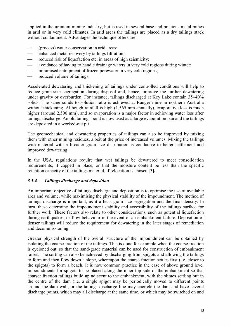
applied in the uranium mining industry, but is used in several base and precious metal mines in arid or in very cold climates. In arid areas the tailings are placed as a dry tailings stack without containment. Advantages the technique offers are:
(process) water conservation in arid areas; enhanced metal recovery by tailings filtration; reduced risk of liquefaction etc. in areas of high seismicity; avoidance of having to handle drainage waters in very cold regions during winter; minimised entrapment of frozen porewater in very cold regions; reduced volume of tailings.
Accelerated dewatering and thickening of tailings under controlled conditions will help to reduce grain-size segregation during disposal and, hence, improve the further dewatering under gravity or overburden. For instance, tailings discharged at Key Lake contain 35–40% solids. The same solids to solution ratio is achieved at Ranger mine in northern Australia without thickening. Although rainfall is high (1,565 mm annually), evaporative loss is much higher (around 2,500 mm), and so evaporation is a major factor in achieving water loss after tailings discharge. An old tailings pond is now used as a large evaporation pan and the tailings are deposited in a worked-out pit.
The geomechanical and dewatering properties of tailings can also be improved by mixing them with other mining residues, albeit at the price of increased volumes. Mixing the tailings with material with a broader grain-size distribution is conducive to better settlement and improved dewatering.
In the USA, regulations require that wet tailings be dewatered to meet consolidation requirements, if capped in place, or that the moisture content be less than the specific retention capacity of the tailings material, if relocation is chosen [3].
5.5.4. Tailings discharge and deposition
An important objective of tailings discharge and deposition is to optimise the use of available area and volume, while maximising the physical stability of the impoundment. The method of tailings discharge is important, as it affects grain-size segregation and the final density. In turn, these determine the impoundment stability and accessibility of the tailings surface for further work. These factors also relate to other considerations, such as potential liquefaction during earthquakes, or flow behaviour in the event of an embankment failure. Deposition of denser tailings will reduce the requirement for dewatering in the later stages of remediation and decommissioning.
Greater physical strength of the overall structure of the impoundment can be obtained by isolating the coarse fraction of the tailings. This is done for example when the coarse fraction is cycloned out, so that the sand-grade material can be used for construction of embankment raises. The sorting can also be achieved by discharging from spigots and allowing the tailings to form and then flow down a slope, whereupon the coarse fraction settles first (i.e. closer to the spigots) to form a beach. It is now common practice in the case of above ground level impoundments for spigots to be placed along the inner top side of the embankment so that coarser fraction tailings build up adjacent to the embankment, with the slimes settling out in the centre of the dam (i.e. a single spigot may be periodically moved to different points around the dam wall, or the tailings discharge line may encircle the dam and have several discharge points, which may all discharge at the same time, or which may be switched on and
43

off). This approach significantly improves the stability of the structure, as the beaches provide physical support to the embankments. Stability generally improves over time as densities increase under the weight of additional tailings deposition. It also removes the finer fractions, with greater potential to liquefy, away from the walls of the impoundment. At the Key Lake above ground facility, discharge took place along one side of the dam, causing beaches to form against the embankments, which on this side were constructed of compacted fill. The slimes and the supernatant pond formed on the other side of the dam that was constructed to water retention standards [23].
This approach does not necessarily guarantee that settlement and consolidation will take place to desired levels. At the Ranger mine (Australia), various discharge arrangements were tried, including subaqueous discharge, central discharge, and perimeter discharge. Perimeter discharge became the preferred approach, and wide beaches developed against the embankments all the way around the dam. However, the densities in the tailings were extremely low in places, with the tailings forming a gel-like matix. These very low densities contributed to the decision to relocate the tailings into a worked-out pit, as access onto the tailings for capping and remediation would have been difficult and expensive.
Tailings discharge control is also critical for in-pit containments. It is desirable to use techniques that will maximise the final density so that more tailings will fit into the available space. Denser tailings will also tend to have a lower permeability reducing release of contaminants into the surrounding groundwater. Avoiding grain size segregation is important to achieve a good consolidation behaviour..
5.5.5. Tailings consolidation
The main mechanism to achieve consolidation of tailings is their dewatering. Dewatering can be undertaken prior to discharge into the tailings containment as discussed above, or in situ,after the tailings have been placed into the impoundment. The various technical options available are summarised in Table 5.
An under-drain gravity system provides an effective means of dewatering tailings. For impoundments already constructed without provision for gravity drainage horizontal drains, a single-well, or well-point systems are recommended for reliable dewatering [101]. Limited recharge rates may restrict the use of a single well. A multiple well system with variable pumping positions may be more effective. The settlement of tailings may be accelerated by stacking additional material and by loading due to cover construction. Dewatering can cause settlements of magnitudes equal to or greater than those caused by placement of the cover material. Therefore dewatering during the operational phase would reduce the need for post-closure dewatering prior to placement of the cover.
Most of the in situ dewatering techniques listed in Table 5 are used at various uranium mine and mill sites around the world. However, information on dewatering techniques is rarely presented in the published literature. Certainly under-drainage and evapo-transpiration techniques are widely used (e.g. Ranger, Key Lake), and wicks have been applied to dewater tailings prior to closure at several mines. At the Atlas mill near Moab, Utah USA, wicks on a 3 m pattern were used in an above-surface, unlined ring-dyke impoundment to consolidate the tailings mass and to reduce seepage to the groundwater system [102].
44

Table 5. Comparison of in situ dewatering techniques for tailings (after [101])
Technique Advantages Disadvantages Under-drains Economical construction
Minimum complexity Existing technology Stabilise tailings during operation
Must be placed before tailings discharge starts Potential clogging from poor construction of precipitated salts Only gravity drainage
Horizontal drains Drain existing impoundments Supplemental advantage with vacuum application
More expensive Requires long drains
Single-well system Technology well developed Dewater existing impoundments
More maintenance & equipment Limited recharge may restrict recharge radius of influence Requires stable access
Well points Same as single well May be used on perimeter to avoid interior access problems Flexibility in pumping positions
Maximum 7.6 m (25’) depth More expensive than single wells
Jet pumping Same as well points Increased effective depth to 30 m (100’) or more
Increased equipment costs
Electro-osmosis with well points
Greater depth than well points alone Applicable to low permeability soils
Expensive Limited effectiveness in acidic pore water
Evapo-transpiration Passive system Limited depth Adverse impact on cover integrity
Sand drains/wicks Dissipate pore water pressures to increase consolidation
Little dewatering capacity
Pervious surround Three-dimensional drainage Requires an open pit
The target of 90% consolidation was not achieved within the requisite time, as only a fraction of the design surcharge load was applied because of lack of funds. However, the degree of dewatering by the wicks was greater than that predicted.
At the Nabarlek mine in Australia, wicks were inserted in a 3 m grid pattern to a depth of 33 m (100 ft) into the tailings (<60 m thickness) in the mine pit to assist in settlement and dewatering [22]. Water expelled from the wicks collected on the upper surface of the tailings and was evaporated through sprinklers placed around the top of the pit walls. The tailings were covered with contaminated material from mill and pad demolition, and capped with stockpiled rock overburden (totalling about 15 m). Subsidence of the cap has been slightly less than the predicted 1.5 m and has been uniform across the cap with only minor cracking in some areas above the edge of the pit, but no subsidence is evident over the tailings mass.
At Seelingstädt and Helmsdorf tailings ponds in Germany (WISMUT), wick drains (Fig. 9) are used on a large scale for the construction of the intermediate layer in remediating the large tailings impoundments (2.5 m 2.5 m grid and 5 m depth). Deep wick drains have also been employed in the Trünzig tailings pond to assist in dewatering of finer parts of the tailings pile.; Loading by placing a temporary embankment over this area of tailings assists in achieving the desired amount of settlement within five years [104].
45

Fig. 9. Construction of wick drainage system on a Wismut tailings pond [103].
5.5.6. Tailings surface treatment
Treatment of the surface of tailings within containments is designed to temporarily reduce radon flux and the generation of fugitive dust prior to final covering. Treatments include the maintenance of a water cover. Depending on the circumstances, this may be incompatible with tailings dewatering and improved settlement through evaporative water loss. Careful management is required to avoid possible instability of embankments as a consequence of wave erosion, or high phreatic surfaces leading to piping or seepage through the walls.
Where beaches are allowed to form continual wetting of the surface to prevent dusting and assist evaporative water loss may be needed. At Ranger mine, for instance, tailings were initially deposited subaqueously to reduce radon flux. However, this approach was replaced by beaching and continual wetting by sprinklers following research that demonstrated that the rate of radon flux was not significantly different between the two techniques.
Another form of surface treatment involves the application of sealants or stabilising agents to reduce the potential for dust generation from dry surfaces, improve erosion resistance, or
46

reduce water infiltration. This approach may be particularly useful at the stage between completion of tailings deposition in a surface impoundment and the removal of decant water, to reduce the risk of surface failure prior to commencement of final covering (e.g. when the facility is kept on a care and maintenance basis in between operational periods). The use of certain sealants is being investigated and developed inter alia in Russia (see Annex XI) and Kazakhstan (see Annex VII). However, like the use of bitumen or molasses, the use of other types of organic binders usually can be viewed only as an interim solution due to their biodegradability.
5.5.7. Decant water treatment
Decant water (supernatant water) contains most or all of the suite of contaminants in the tailings. It may readily escape to the environment in the case of overtopping, breaks in pumping lines, or failure of the drainage system. The decant water is either returned to the mill as part of the take-up water, thus reducing the draw on uncontaminated water, or is treated and released to the environment.
In arid climates, the standard practice for decant water management is the evaporation of water in ponds, sometimes with the assistance of spray systems.
5.5.8. Seepage control
Most tailings impoundments by their very nature will produce seepage at some stage during their life. Seepage will continue after closure due to local groundwater in-flow or surface infiltration unless adequate measures are taken to control this. The long term performance of liners is not guaranteed, and seepage may increase because of imperfect joining seals and accidental damage during installation, penetration by rock fragments etc. The design objective for new facilities and the main target for impoundment remediation is the elimination of all factors that could lead to continued seepage. This is the design target for all of the UMTRA sites. For example, Tuba City, Arizona, modelling calculations support the conclusion that continued seepage will occur at a very low rate. This is confirmed by monitoring over a period of ten years. This site is located in an arid environment. In more humid climates and under other site specific conditions, some seepage is likely to occur. Good practice therefore requires the installation of seepage collectors and treatment systems. Long term treatment implies a commitment to costs in the future. Therefore any such system is best planned in such a way that passive treatment will eventually be adequate However, passive treatment systems cannot be regarded as walk-away solutions. Acidity is the master variable controlling the behaviour of most radionuclides and other toxic metals. A variety of ways of treating acid rock drainage (ARD) and acid mine drainage (AMD) have been developed (see also Section 7.6), such as slag leach beds and oxic or anoxic limestone drains [105]. A recent IAEA report provides more details on ARD/AMD treatment systems, including biological systems [106].
At Ranger mine a seepage interception system was installed around the perimeter of the embankment impoundment. The seepage is monitored, collected in a sump, and pumped back into the tailings dam.
At Key Lake, seepage collection is engineered into the tailings facility structure, through placement of a filter blanket under the tailings pile. Seepage pore water is expelled into the filter as a result of increasing overburden pressures and hydrostatic head as the tailings pile gets thicker. The seepage is pumped to the waste treatment circuit for treatment [23].
47

Permeable reactive liners and barriers are an important new development in the management of tailings seepage in situ [107]. These make use of chemically reactive materials such as zero-valent iron, peat or compost, carbonates, phosphates, zeolites etc. to sequester mobile contaminants from the seepage water [106] [108].
5.5.9. Covers
5.5.9.1. Design objectives
The objectives of cover installation on uranium mill tailings are to minimise radon and dust emission, shield the environment from gamma radiation, minimise water and oxygen infiltration, control erosion, and to form an aesthetically acceptable landscape that fulfills these technical objectives.
5.5.9.2. Historical review of covers in the USA
The many years of research into cover design for effective long term isolation led to a gradual evolution of cap design, based on an improved understanding of the probable behaviour of early designs in response to natural erosive forces over the long term, and an appreciation of the benefits of harmonising designs with natural forces by incorporating vegetation and landscape evolutionary parameters [109]. Early designs focussed on radon attenuation and longevity of the structure. They comprised three layers: a compacted soil layer that formed the radon barrier, a rock rip-rap layer to provide protection of the radon barrier from erosion, and a layer of coarse sand between the two that was designed to act as a bedding layer for the rock and as a drainage layer for rainfall to percolate off the slopes of the containment structure. The design of the first rock cover constructed by UMTRA is shown in Fig. 10. The cover at Shiprock, New Mexico, comprises a relatively thick (over 2 m) compacted silty sand radon barrier layer and a 300 mm rip-rap layer. The greater thickness than usual of the radon barrier that was needed for radon attenuation reflected the relatively coarse texture of the material used to construct it, and high 226Ra concentration in the tailings [110]. This cover was installed in 1985. In 2001, the disposal cell was investigated with a piezocone and although the study did not meet the full objectives to completely characterise the moisture distribution, it appears that the cover is performing as designed [92].
After the US EPA published draft groundwater quality standards in 1987, greater design emphasis was based on low permeability for the compacted soil layer. In 1989 UMTRA adopted a standard for low-permeability caps that required a saturated hydraulic conductivity of less than 1·10-9 m/s, and a permeability not less than the underlying tailings so as to prevent water ponding in the tailings mass. The approaches taken to achieve the standard were either highly compacted native soil, or bentonite-amended soil.
Fig. 11 shows a cap design incorporating a low-permeability cover provided by about 0.5 m of highly compacted silty clay soil, the upper two thirds of which were amended with bentonite. In contrast to the Shiprock cover, this one provided a considerably more efficient radon barrier. The design also included covers for protecting the radon barrier against erosion, frost, and infiltration.
48

1.0 - 1.5 ft Riprap
Radon barrier: clay/silt
Tailings
7 ft
1.0 - 1.5 ft Riprap
Radon barrier: clay/silt
Tailings
7 ft
Fig. 10. Cover design for the UMTRA Project Shiprock disposal structure, New Mexico, after [111].
1.0 ft Riprap
Radon barrier: clay/silt(upper foot bentonite amended)
Tailings
3.0 - 7.5 ft
0.5 ft
0.5 ft
1.0 ft
Drain/Bedding: Coarse Sand
Sand drain
Frost protection
1.0 ft Riprap
Radon barrier: clay/silt(upper foot bentonite amended)
Tailings
3.0 - 7.5 ft
0.5 ft0.5 ft
0.5 ft0.5 ft
1.0 ft
Drain/Bedding: Coarse Sand
Sand drain
Frost protection
Fig. 11. Cover design for the UMTRA Estes Gulch containment structure, Colorado after [111].
49

2.0 ft
Gravel admixturein upper 8 in. of topsoil
Radon barrier: clay/silt
Tailings
2.0 ft
Topsoil
Capillary barrier and drain (clean sand)
Growth medium and frost protection(fine-grained soil)
Biointrusion layer(cobbles filled with soil)
Fine-grained soil
1.0 ft
1.3 ft
1.2 ft
Geotextile separator
Flexible membrane liner
Vegetation
1.0 ft
Wat
er st
orag
e la
yer
2.0 ft
Gravel admixturein upper 8 in. of topsoil
Radon barrier: clay/silt
Tailings
2.0 ft
Topsoil
Capillary barrier and drain (clean sand)
Growth medium and frost protection(fine-grained soil)
Biointrusion layer(cobbles filled with soil)
Fine-grained soil
1.0 ft1.0 ft
1.3 ft
1.2 ft
Geotextile separatorGeotextile separator
Flexible membrane linerFlexible membrane liner
Vegetation
1.0 ft
Wat
er st
orag
e la
yer
Fig. 12. Cover design for the UMTRA Monticello containment structure, Utah after [111].
A design shift in the late 1980s and 1990s resulted from the observation that ecological plant succession is inevitable and that continued intensive maintenance is impractical over extended time-scales. Fig. 12 shows a design that takes these factors into account [112]. The multi-layer cover design combines fundamental ecological principles with engineered barriers. The capillary barrier under a thick soil ‘sponge’ mimics the natural soil profile, in which thick loess stores precipitation that is eventually lost through evapotranspiration, thus maintaining unsaturated conditions in the subsoil. The cover is also designed to control radon flux, bio-intrusion and erosion, and to protect critical interfaces from frost. Studies of natural analogues suggest that the cover performance is likely to improve over the 1000-year design life [113].
A key theme is that whilst the same general principles should be applied, designs must be site specific and based on data collected at each site. This concept appears to widely held (see Annex XIII). Experience in the Western USA has shown that vegetative covers are not always viable in arid climates. This could be overcome with a multi-layer cover that addresses the objectives defined above, or by building a more traditional design using a compacted clay layer covered by rock.
Some caps have been in place long enough for useful data to be available on their performance (e.g. Beaverlodge [114]). Thus the development over time of a capillary barrier was assessed after a twelve year operational period [115]. Some ironoxyhydroxide precipates originating from acid drainage were found, but these did not reduce permeability significantly. but the issue of long term stability is still a major concern.
The design life of UMTRA structures is 1000 years. However, satisfactory containment may be required for time-spans between one and two orders of magnitude greater than this in order to guarantee effective isolation until levels of radioactivity have declined sufficiently.
50

Attempts are being made to quantify longevity of structures through estimations based on short term testing [116]. Estimation of proposed landform stability in the very long term is based on modelling, such as the modelling conducted for the Ranger mine constructed landform [117]. The results can help to identify areas of poor performance, which insight then is fed back into design adjustments.
Cover performance is not only of concern in the context of uranium mill tailings, but in any near surface repository and landfill design. In the US, a programme to compare different cover design under different climatic conditions was initiated [118].
5.5.9.3. Design Criteria
The design criteria for covers are related to the remediation objectives, and address geotechnical, radiological, hydrological, geochemical, ecological and aesthetic requirements. In general, covers comprise multiple layers, each with a specific function. For example, clay layers are typically used to control radon emanation and water infiltration. Vegetative covers control wind and water induced erosion and moisture infiltration by encouraging evapo-transpiration. Coarser material is used for moisture storage, as drainage layer and capillary break, and to discourage animal and human intrusion. A large body of information exists relating to the design of municipal landfills in various countries, e.g. [119], that may be indirectly applicable to uranium mill tailings closure and remediation.
Longevity – Longevity is an important consideration in that covers may need to be engineered for life spans of the order of 200–1000 or more years. Erosion resistance is the key feature here. The other funcitionalities listed below must also be retained over the design life.
Sealing and shielding functions – Gamma ray shielding can generally be achieved with a 0.5 m soil layer. To control dust, a vegetative cover based on an adequate soil layer as a plant growth substrate can be applied. A rock cover can also serve the purpose of eliminating the fugitive dust problem. Radon emanation typically is controlled by the application of a compacted clay layer and a reletively thin layer of compacted soil appears to be sufficient. Radon diffusion modeling assists in deriving the relevant design paramenters and material properties. The resistance to damage in freeze-thaw cycles may need to be investigated carefully.
Water infiltration – Infiltration of atmospheric precipatation can be managed by the proper design of the sealing layer. The nature of the sealing material, moisture and density of the material at placement, and placement techniques are of upmost importance for achieving design criteria. Typical saturated hydraulic conductivity specified for sealant layers are of the order of 10-9 m/s or less. The performance can be assessed by evaluating the hydrologic water balance (Fig. 13). Laboratory tests are generally not representative of true field conditions and can produce results that differ from field conditions by as much as two orders of magnitude. In general, field (lysimeter) measurements are a more appropriate method for parameter, as hetero-geneity in permeability distribution is a function of scale. To achieve the necessary low permeabilities, sealant layers have to be compacted to obtain maximum dry density at optimum moisture content, to typically meet or exceed the 95% Standard Proctor density, e.g. [120]. These criteria are best demonstrated by the use of field test sites.
51

Fig. 13. Water balance in a covered tailings impoundment.
Gas Infiltration – Design criteria aiming at limiting water infiltration and radon emission will generally also effectively control the inflow of gasses. It is important to prevent the infiltration of oxygen into tailings, as this will result in oxidation reactions that could lead to acid generation and, hence, mobilization of contaminants. The introduction of oxygen dissolved in water is generally a more important mechanism than gas infiltration.
Erosion prevention – Erosion can be prevented by surface countouring that reduces and breaks slopes, the use of rip-rap or cohesive clay layers, and the development of vegetation covers. Vegetation covers provide good protection against erosion, but require site specific research to establish, which plant ecosystem would likely to be sustainable under the given conditions. Some supportive measures, such as application of polymer coatings, maybe needed to help establish the vegetation cover. Natural analogue studies provide a valuable tool for predicting long term erosion impacts.
Water storage layer – A water storage layer, consists of multiple layers above the sealing layer, that act as a ‘sponge’, adapting to weather cycles. Inter alia, this layer prevents the drying-out of any sealing clay-layers. Drying cracks in the sealing layers would compromise their retaining capabilities for gases and infiltrating waters. In order to obtain the desired properties, this layer should be at least 1.5 m thick [120].
Bio-Intrusion – In many areas, burrowing animals or deep roots can penetrate the sealing layer resulting in a loss of functional integrity. Provision can be made for the protection of the integrity of the sealing layers. For instance covering layers can be made thick enough and layers of rip-rap introduced that tend to discourage burrowing animals. Such layer, if thick enough, would also help to discourage humans from digging-up the tailings material.
5.5.9.4. Potential failure mechanisms
Inadequate design and poor implementation can result in the failure of tailings covers. Longevity objectives depend on adequate care and maintenance. Possible causes of cover failure include:
52

Differential settlement Dessication cracks Bioturbation Root penetration Human and animal intrusion Extreme weather events Changes in the design base (e.g. climate changes)
Cover design may consider these factors in a probabilistic approach. Where possible, engineering design intends to prevent such events, but a certain amount of care and maintenance is likely to be inevitable [121]. With recent extreme events of flooding in Europe and elsewhere, long-established design parameters, such as maximum rain intensities and rainfall- function for catchment areas have come under scrutiny.
6. OUTSTANDING ISSUES
6.1. Overview
The main issues of public concern regarding mill tailings containment are the risks of catastrophic failure and continuing discharges that may lead to loss of life, property, infrastructure, to detriment to the environment and public health. The overall trend in the frequency of catastrophic failures has been downward over the past decades, although the larger sizes of newer impoundments mean that catastrophic failure may have potentially greater impacts than previously. No catastrophic failures have been reported for purely uranium tailings impoundments for more than 20 years. On the other hand, chronic releases of radon, dust and contaminated water and the associated potential health impacts and environmental contamination are a concern at many sites around the world.
The underlying causes for chronic release have been the subject of much research, as have been applicable methods for remediation. There is a large body of information available, focussed on major uranium production centres in western countries. Table 6 at the end of the chapter sets out the alternatives for uranium mill tailings containment as discussed previously, and attempts to evaluate the advantages and disadvantages of each method. Similarly, Table 7 sets out the alternatives for uranium mill tailings isolation and stabilization discussed in Chapter 5.8, and makes observations of the advantages and disadvantages of the different approaches and techniques.
It should be noted that one major driving force behind technological developments are tighter legal requirements and regulations.
6.2. Issues relating to the physical properties of tailings
The major root cause of catastrophic failure and ensuing dispersal of tailings material is the poor settling behaviour of tailings. Consequently, much research and technological development focuses on effective and cost efficient methods to dewater tailings either before or after impounding.
53

The physical properties are closely related to the chemical properties of tailings, as these typically constitute a finely dispersed, gel-like system.
(1) Research into the (site specific) dewatering behaviour of tailings with a view to improve dewatering is needed.
Table 6. A comparison of the advantages and disadvantages of the different approaches to uranium mill tailings containment [compiled by S. Needham].
Disposal option
Advantages Disadvantages
Above ground > Can operate simultaneously with mining > May be cheap to establish if tailings used in
construction > Valley fill sites may have low construction costs > Whole tailings can be contained > Tailings pond can also function as evaporative
pan to assist in mine water management > Most widely used > Tailings easily accessed for reworking if
required
> Authorities may regard this type as only temporary storage & tailings may need to be relocated e.g. below ground level at end of mine life
> May require construction of associated structures to minimise risk of environmental impact in the case of failure, or to collect/treat seepage etc
> Seepage control essential > Expensive if built as water containment structure > Post close-out settlement may take a long time and lengthen
period before operator can be released of responsibility > May need long term maintenance > Long term risk of tailings spill, increasing as structure
weathers and erodes > Increases land area impacted by mining > Airborne and waterborne dispersal of contaminants possible
following erosion etc Below ground: in pit
> Very long term containment possible > Unlikely to ever require maintenance > Whole tailings can be contained > Pit preparation costs unlikely to be as high as
above ground options > Airborne dispersal of contaminants effectively
impossible > Structural failure of containment virtually
impossible
> May need pervious-surround work to minimise ground water contamination risk
> Construction cost of impermeable containment could be high if suitable pit not available
> Not normally possible to operate simultaneously with mining at the same location
> Requires a suitable pit to be available pre-mining, or for all ore to extracted prior to milling (e.g. Nabarlek)
> May involve double-handing of tailings if no pit available at commencement
> Re-claiming of tailings if required for further treatment will be difficult owing to depth
Below ground: underground mine workings
> Very long term containment possible > Unlikely to ever require maintenance > Can possibly incorporate whole tailings > Can be operated simultaneously with mining > Airborne dispersal of contaminants effectively
impossible > Structural failure of containment virtually
impossible
> Slimes may need to be contained separately > Need suitable groundwater conditions > Mine waste water management system needs to be able to
cope with evaporation requirements > Tailings not available for reprocessing
Below ground: purpose-built containment (underground void or surface pit)
> Very long term containment possible > Unlikely to ever require maintenance > Whole tailings can be contained > Can be operated simultaneously with mining > Airborne dispersal of contaminants effectively
impossible > Structural failure of containment virtually
impossible > Site can be selected in low-permeability country
rock > Benign rock available for unrestricted use in
construction
> Construction required before milling commences > Mine waste water management system needs to be able to
cope with evaporation requirements > Suitable site may be remote from mill and increase
slurry/paste transport & infrastructure costs > Paste stabilization normally necessary for underground and
optional/preferable for pit.
Deep lake > Can operate simultaneously with mining > Cheap to establish > Whole tailings can be contained > Very long term containment possible > Unlikely to ever require maintenance > Whole tailings can be contained > Airborne dispersal of contaminants effectively
impossible > Structural failure of containment virtually
impossible
> Authorities may not allow this approach to tailings disposal > Requires nearby water body not otherwise used for social or
economic benefit (i.e. fishery, water supply, recreation) > Risk of water contamination and tailings redistribution from
disturbance by major flood of changed climatic conditions
54

Table 7. A comparison of the advantages and disadvantages of methods for stabilizing and isolating uranium mill tailings [compiled by S. Needham].
Methods Advantages Disadvantages Containment preparation: Low-permeability membrane High short-medium term security against
seepage; easily applied to floor and walls of surface containments.
High cost; prone to accidental damage; difficult to repair after tailings discharge commenced; unknown long term performance; application limited to above ground containments; cannot be retrofitted.
Clay seal Permeability decreases with overloading; low cost if local material available.
High cost if local materials unavailable; application limited to above ground and in-pit containments; cannot be retrofitted.
Grout Targets known weak zones; ease of application.
Misses unknown zones of weakness; grouting compound may degrade on interaction with tailings pore water, cannot be retrofitted; possible high drilling costs involving specialist equipment
Permeable surround Potential long term high security around entire containment against groundwater contamination; low maintenance.
Suitable high-permeability material needed; may clog; application limited to below ground containments; cannot be retrofitted. High cost (but distributed though operational phase)
Under-drain/basal filter bed Aids settlement. May clog; cannot be retrofitted; water disposal must be accounted for
Tailings preparation: Neutralization Reduces acid producing potential and
mobility of U and other heavy metals. Availability and cost may affect viability
Thickening Reduces water content of tailings; useful in low evaporation regions to achieve water loss.
Increased pumping costs; or alternative placement techniques.
Paste Allows addition of compounds to significantly improve chemical and physical stability of tailings pile and containment.
Present use limited to underground containments; longevity unknown; tailings probably not recoverable.[note: area of considerable development potential, research results discussed in Chapter 7].
Cycloning High stability product; provides sand-grade material for construction; removes main contaminants.
Slimes disposal
Tailings discharge and depositionSlurry beaching Increase stability of embankment walls;
easier ponding and collection of decant water.
Not applicable underground
Thickened tails placement Improved immediate surface stability and access; improved control of placement (e.g. layering)
Higher transport costs (pumping or trucking)
Dry cake placement High immediate surface stability. Higher transport costs (ie trucking). Barrier/reactive layers High control over design and placement;
permits tailoring to address variations within tailings pile etc; potential wide range of treatments available.
Suits only paste or dry cake deposition of tailings; high placement costs (pumping or trucking), largely untested technology [note: area of considerable development potential, research results discussed in Chapter 7].
Tailings dewatering at discharge:Thickened tailings Reduce water content problems, especially
in low evaporation areas. Reduced use of clean water.
Higher transport costs (pumping or trucking) compared to slurry
Paste tailings Reduce water content problems, especially in low evaporation areas; allows addition of chemical and physical stabilisers.
Long term performance and effects on diagenesis etc unknown
Dry cake Removes water removal and stability problems, significant reduction in leaching and groundwater contamination risks; potential for seismically active, cold, arid regions. Reduced use of clean water.
Untested in uranium mill tailings
Tailings dewatering in-situ:Under-drains Improves settlement density, reduces
instability and chemical contamination. Cannot be retrofitted; may clog.
Horizontal drains High improvement to settlement density, reduces instability and chemical contamination; design may be modified during operation.
Cannot be retrofitted; may clog.
Wells/jet pumps/electro-osmosis
Improves settlement density, reduces instability and chemical contamination; can be targeted to specific sites. Suitable for ex-post treatment.
May require closely spaced grid of wells with attendant higher costs (see also Table 4).
55

Methods Advantages Disadvantages Evapo-transpiration Some improvement to settlement density,
reduces instability, inexpensive. Restricts access to tailings surface; of limited benefit once supernatant liquid evaporated unless used in conjunction with wells or wicks; no removal of contaminant load.
Sand drains/wicks Some improvement to settlement density, reduces instability, inexpensive and low maintenance. Suitable for ex-post treatment.
May take many years to reach dewatering capacity. Surface loading speeds it up.
Tailings surface treatmentWater cover Limits radon flux, dust Negates dewatering as an option to improve settlement
density. Must be removed and followed by dewatering/settlement works prior to remediation.
Wetting Reduces dust and radon flux; assists in evaporative water loss.
Components need regular inspection, maintenance, and switching/moving.
Sealants Reduces dust, infiltration, improves access to tailings surface; good temporary protection between depositional or remedial stages.
Suitable only for short term protection.
Decant water treatmentRecirculation to mill Reduces clean water uptake, low cost, suits
no-release criteria. Possible build-up of agents may decrease mill circuit efficiency.
Treat and release Contains contaminants within the mine system.
Public perception of uncontrolled environmental harm; probable environmental impacts in event of system failure.
Seepage controlSeepage detectors Provides early warning and allows early
intervention in event of significant seepage Costly; in themselves do not treat the problem; difficult and expensive to retrofit.
Collector wells Targets known confined seepage zones. Limited sphere of influence; unlikely to collect seepage from unknown/new seepage points; requires monitoring wells to validate performance.
Interception drains Minimises transfer of contaminants to groundwater or surface water systems; can extend around perimeter to provide high levels of assurance; essential backup for all operating tailings facilities.
Requires monitoring wells to validate performance.
Return to containment As for decant water treatment Essential Treat and release As for decant water treatment Essential Recirculate to mill As for decant water treatment Essential Groundwater monitoring Provides essential information for effective
water management during operational phase Not practical for long term management/stewardship post closure
CappingEngineered design High security short term (<1000 years);
well-known technology; extensive experience, guidelines, geotechnical expertise.
Unknown long term (1000–50000 years) performance; probable high future maintenance costs; incompatible with natural processes, forces and systems; poor aesthetics.
Ecological design Caters for/conforms with natural processes; enhances prospects for long term security against environmental harm; probable low future maintenance costs; good aesthetics
Unknown technology and costs; possible long lead time for research to deliver sufficient site specific knowledge to factor into design.
6.3. Issues relating to containment
A recent review of risk assessment and contingency planning in the management of mill tailings concluded that there is no such thing as ‘fail-safe’ facilities for tailings management [82]. Neither regulations, design specifications, nor management systems can be relied upon in isolation to provide assurance against containment failure: all three must be applied, in a framework of quality assurance and post-closure care and maintenance, to deliver a high probability of tailings containment security. Examples exist of failure related to containments not being built as designed; regulators not checking that all requirements were provided for in construction and operation, and worst-case scenarios not being taken into consideration in deriving design specifications. It is therefore critical to ensure that:
(2) containment design is based on comprehensive, site -specific risk analysis; (3) containment construction follows design specifications rigorously;
56

(4) appropriate operating procedures, coupled with quality assurance are adhered to, including a regulatory system that checks that all design and operational requirements are applied during construction, throughout operational life, remediation, close-out and during the stewardship stage.
There is much information in the literature on the high cost of remedial works undertaken at areas contaminated by past practices in uranium tailings management, in particular from the UMTRA programme in the USA, remediation activities in Germany, other European countries and Australia. It is clear that in cost terms, prevention of contamination is much more effective than cleaning it up afterwards. This is corroborated by experience from other mining industries. In relation to the general performance of uranium mill tailings containments, the main concerns relate to longevity of containment, and seepage to groundwater. On the other hand, current knowledge and practices relating to radiation control, dust, and security can be considered generally satisfactory. Areas for consideration in relation to longevity of containment and environmental impact via seepage are:
(5) a comprehensive site specific risk analysis that includes an assessment of likely environmental impacts for both the operational and post-operational stages;
(6) a containment design that incorporates components designed specifically to prevent environmental impact to the highest level achievable during the operational life of the containment within reasonable cost;
(7) a choice of the type of, and site for, the containment that considers the long term risks and costs. For example, higher tailings slurry pumping costs to take advantage of an old pit in the district may be preferable to construction of a dam adjacent to the mill where seismicity, available construction materials, surface water flow etc may represent significantly higher risk of failure during the life of the containment.
(8) design approaches that develop concepts that offer confidence beyond a 1000 year design life provided through conventional engineering design. Such concepts of containment performance and containment life may include features that enable natural processes to interact with the containment and the tailings within it in a way that improves long term stability rather than diminishing it (ecological design).
6.4. Issues relating to tailings chemistry
Whilst some research into tailings chemistry, and considerable research into fixation of uranium, is being undertaken, the knowledge of tailings chemistry appears to be incomplete, and therefore, the potential environmental impacts of tailings water and its mixture of heavy metals and other toxic compounds are not fully understood. There is little acknowledgement in the research literature published in the uranium sector that non-radioactive constituents, particularly heavy metals, arsenic and organics may have a comparable or greater impact than uranium and its progeny. The non-uranium mining industry has identified acid mine drainage as the major environmental issue it faces, and major world-wide initiatives have been developed to organise research into mitigating the problem. Clearly, removal of the acidity problem reduces the mobility of metals, including uranium, and significant environmental problems can be avoided. There is valuable information available in non-uranium mining research that could be beneficially transferred to the uranium mining and uranium mill tailings area. More knowledge is required on the combined chemical behaviour and toxicity of the total chemistry of uranium mill tailings effluents.
57

(9) There is significant knowledge coming to hand about methods to reduce the chemical mobility of uranium that focuses on application after deposition, for example as barriers or as agents to assist in effective capping. Whilst some attention has been given to the possible application of this technology at or before tailings deposition, the opportunities should be explored more fully in order that seepage is less likely to be generated in the first place. A key factor in the generation and mobility of tailings water is obviously the water content of the tailings. Significant research progress is being made into thickened tailings and paste technology to generate low-water and even dry tailings. These methods are now widely applied in non-uranium metal mining, but cannot easily be applied in retrospect due to high costs. Attention may need to be given to assessing the suitability of several technologies for tailings stabilization (water contents reduction, cementation, various chemical fixation techniques), either before, or during placement into the containment.
Lack of knowledge on the evolution of the tailings body is a significant limitation on modelling of long term stability and performance of the containment. Little is known of the controls on and effects of diagenetic reactions, the stability of new mineral parageneses, and their long term evolution and performance. For instance the porewater pH and Eh may change over time resulting from successive mineral parageneses. The solubility of metals, including uranium is governed by the Eh and pH conditions within the tailings pile. Diagenetic processes will also be governed by reaction kinetics. The role of biological processes, for example the reduction of sulfate by bacteria, may also need to be considered.
(10) a better understanding of the long term mineralogical changes within uranium mill tailings would allow the design of chemical treatment likely to promote desirable processes that could, if cost-effective, be used to enhance the stabilization of tailings impoundments.
6.5. Passive systems
During remediation and after final closure, low levels of environmental contamination may still continue to exist. Passive technologies may be employed to deal with continuing seepage and residual groundwater contamination. These systems are being increasingly used at many uranium mines and tailings facilities to treat effluent by using the assimilative capacities of various naturally occurring processes [106]. They include adsorption onto soil particles, absorption by certain minerals and organic compounds, uptake by vegetation, uptake and fixation by microorganisms, and (co-)precipitation as various mineral species- often as iron compounds. Research into the processes at work is extensive, as the potential for these ‘bio-reactors’ is being widely pursued by all areas of the mining industry, as well as other industry sectors such as mineral processing, chemicals fabrication and abattoirs.
Passive systems range from engineered systems, such as reactive barriers, through enhanced natural wetland systems, to a reliance on natural attenuation processes [106]. In most cases, these are not walk-away solutions, but require a detailed understanding of the physical and chemical systems involved, adequate care and maintenance and long term monitoring to verify performance objectives [122]. It is worth noting that contaminants attenuated in passive systems may be re-released by changing environmental conditions and that the removal of contaminants from seepage results in the creation of new contaminated solids. These may require later remediation themselves, if not disposed of safely. These systems are generally applied as combinations with other passive or active components.
58

The use of the term ‘passive systems’ reflects the hope that the level of intervention required at closed sites in order to achieve adequate levels of environmental protection would be minimal or none. However, there is little information available on the sustainability and time-dependent effectiveness of these natural processes. It is likely that the capacity for such systems to continually take up contaminants has a finite limit. ‘Natural analogue’ studies as have been undertaken in the context of geological disposal of radioactive wastes [113] [123] may also hold a clue for the long term behaviour of tailings impoundments.
Current thinking is moving to the concept of ‘minimal intervention’ that recognises the likelihood of a finite assimilative capacity for natural systems. A wide range of these questions was discussed for instance at recent conference in a dedicated session of the ustilization and limitations of natural attenuation as a long term environmental protection approach [124] [125] [126] [127] [128] [129] [130] [131].
Concepts for the acceptable isolation of uranium mill tailings must, in view of the very long time frame involved, accept the inevitability of interactions between the tailings pile and its containment with the natural environment. Indeed, the concept of the ideal tailings isolation arrangement is one, in which the physical and chemical processes in the tailings eventually make use of natural attenuation processes so that nature is harnessed to improve stability with time. The concerns for long term stability and likelihood of failure, based on conventional engineering methods, are thereby reduced. ‘Natural forces’ become an assistant to longevity instead of its enemy; the overall design concept becomes one based on harmony with nature.
(11) Studies into natural processes to assimilate effluent from tailings piles may be promoted to determine their capacity to improve stability over long time frames, and thus provide feedback into improved physical and chemical systems designed for present-day approaches.
(12) It may be worthwhile to keep an open mind for the possibility of future impoundment design and placement techniques that may harness natural processes to reduce long term risk of failure and environmental harm by effectively assimilating the tailings pile and containment into the environment.
7. NEW APPROACHES AND RESEARCH
7.1. Overview
A large proportion of research relevant to management of uranium mill tailings has been produced since the early 1980s mainly in the USA, Spain, France, Canada, and Germany. In all of these countries, the government recognised the potential health risks posed by improperly closed and unremediated uranium tailings and stimulated research towards solutions, passed legislation, and allocated funds to enable clean-up to begin. A comprehensive and detailed review of the level of knowledge of uranium tailings management developed in the Canadian National Uranium Tailings Programme is given by [8]. During the same period, new major uranium mining and milling operations were opened. Through their licensing and operational requirements, new methods of tailings management had to be developed, based on extensive research in the uranium and non-uranium mining industry.
59

There are, therefore, two important sources of information on new approaches to uranium tailings management. These stem from the remediation of old tailings impoundments and from the development of new mines and mills. The general trend of these approaches is towards site specific solutions, based on risk assessment and with the objective of long term isolation of tailings from the environment, utilizing natural processes as far as possible.
7.2. Design and siting of containments
Research in this area is commonly undertaken through a risk assessment framework that considers all reasonable options with the objective of selecting the preferred alternative to minimise the probability of failure and environmental harm. Examples include general principles in risk assessment and design [132], developing site specific risk assessment methodologies (e.g. [133]), and selection of the lowest-risk alternative for a specific region, such as concluding that subaqueous deposition is best for decommissioning at facilities at Elliot Lake in Canada [94].
Another line of research concerning design and siting is the development of methods and models for prediction of long term stability. One area of investigation is the development of short term testing techniques from which reliable long term predictions of stability can be made ([116], using UMTRA repositories as the study sites). Long term column tests also provide data on which to base long term predictions [134]. Another is the development of computer modelling based on ground-truthed parameters, such as regional erosion rates, present and likely future climate conditions, and ground surface conditions measured on waste rock dumps and natural analogue sites. This approach has been applied to estimate longevity and likely failure points for the Ranger mine landform contained in the mine closure plan [117] [135]. The concept of ecological design of tailings repositories is advanced for the uranium mill tailings deposits in Germany for reasons of reduced risk of failure, lower maintenance requirements, and harmonizing with natural processes [136]; this work concludes that inherently stable landforms are the way of the future in tailings repository design.
Research is also continuing into the effects of vegetation development and root penetration on the stability and longevity of covers. Lessons learned from UMTRA research and observation show that encroachment by vegetation onto covers is inevitable [137]. Issues such as vegetative encroachment on rock covers may have to be managed under long term care and maintenance [121] until a better understanding of these issues has been achieved.
In humid climates, vegetation will develop in any uncontrolled area. Vegetation is used for erosion control and the management of the water balance within covers. Root penetration may however pose a problem. Since root shape and penetration can have a major influence on water balance, a large amount of experimental work has been undertaken in this field world-wide. Extensive research has been carried out to investigate the natural encroachment of vegetation onto barren sites. This will give an idea of the possible plant succession on tailings impoundments. Planning of vegetation covers aims to achieve a sustainable vegetation cover, relying on predicted natural succession, rather than on active management. Vegetative cover designs normally build on indigenous plants as far as possible, and try to avoid becoming a source of invasive alien vegetation, following the principles of ecosystem sustainability.
7.3. Physical stabilization
Research into physical stabilization can be broken down into issues that deal with consolidation of existing tailings piles, enhancement of settlement rates and densities,
60

application of paste technology to uranium mill tailings, and developments in paste technology and grouting systems.
7.3.1. Consolidation
Consolidation occurs naturally in existing tailings piles, leading to a decrease in volume and an increase in geomechanical strength. The consolidation rate generally decreases exponentially, ultimately becoming very slow. Consolidation rates are dependent on pile thickness, grain size distribution, (initial) water content, and pore pressure or overburden. It may be enhanced by dewatering and overburden material.
Tailings settlement/consolidation studies include site specific studies at Ranger mine, Australia, in Thuringia, Germany and Saskatchewan, Canada. At Ranger, high-energy peripheral discharge of tailings (i.e. they cascade down over benches from a pipe at the top of the pit wall) results in rapid segregation of the coarse fraction near the pit wall on one side, such that the centre of the pit is filling with fine tailings and slimes [89]. Similar situations, where deep piles of very fine, low density tailings have been allowed to accumulate in pits have caused serious problems for decommissioning through very long settlement periods and excessive differential settlement of the surface [138]. A different tailings discharge system has been recommended for the Ranger pit, similar to the Deilmann pit system [139], that aims to limit segregation, enhance consolidation, while achieving a low hydraulic conductivity.
In Thuringia, laboratory tests have been undertaken to determine hydraulic conditions within Wismut tailings [104] so that consolidation modelling (applying non-linear finite strain consolidation theory) could be refined. Thus estimates of settlement rates and the time taken to achieve desired settlement densities can be improved. This information can then be used to parameterise techniques such as grid spacing of deep wicks, or surface loading rates, to achieve the required settlement performance within the five-year target time. Comparison of modelling results and observed tailings profiles in the Culmitzsch impoundment suggests that the degree of consolidation is sensitive to the thickness of the slimes zone, and not to tailings pile thickness [140]. The settlement of fine tailings cannot be predicted using the consolidation theory of Terzaghi, which is applicable to homogeneous, soil-like tailings only. The behaviour of fine material depends on water content under a time dependent load, and finite strain models are necessary [27] [141]. The 1-D model of Schiffman has been further developed by Wismut to a 2-D model that can be applied to real-world 3-D problems [140].
At the Key Lake and Rabbit Lake facilities, Saskatchewan, Canada, adequate consolidation was not achieved due to formation of ice within the tailings during winter. Various techniques have been used with partial success to address this problem (see Annex II).
The material type and the deposition method produce different patterns of heterogeneity within tailings impoundments. Accurate mapping in three dimensions is therefore necessary to predict the settlement behaviour within a tailings impoundment.
Total settlement of a tailings pile can range from a few percent up to 30%, over varying periods of time, but generally less than five years (see Fig. 14 for an example). Most settlement occurs in the initial years. Typically at least 90% of the settlement should have taken place before a cover can be installed. The progress of settlement can be monitored by surveying settlement plates. Settlement can be accelerated by loading with a surcharge and various dewatering and compaction techniques.
61

25
25.5
26
26.5
27
27.5
28
28.5
29
29.5
30
11000 12000 13000 14000 15000 16000 17000
time [d]
taili
ngs
heig
ht [
m]
max. load
end of filling
Fig. 14. Evolution of settlement of fine slime tailings under a surcharge of 300 kPa (ca. 15 m cover). It is assumed that the surcharge increases lineraly from 0 to the maximum over 1 year.
Central part of Rožná K1 tailings pond (see also Annex IV).
Other research includes the addition of material to increase consolidation rates [142]. For instance, shredded plastic is used to improve permeability and speed up settlement.
7.3.2. Paste technology
Research into paste technology is substantial and created considerable interest in the industry [143]. In very simple terms the production of tailings paste includes the thickening of a tailings slurry to a low moisture content to produce a pastelike material that is still pumpable. The moisture content must be low enough that esentially all pore fluids are held as colloidal moisture or by capillary forces. Synthetic flocculants are added to achieve rapid settling of dense fine solids aggregates, a deep bed thickener to promote self weight consolidation in the settled solids and dewatering channels to relieve the excess pore pressures.
There is, however, little research that relates specifically to paste technology in uranium mill tailings. Potential application of the technique was reviewed in relation to the recommencement of uranium mining and milling at Canon City, Colorado. It was found to satisfy the requirement of new state regulations that specify minimal free drainage under gravity from any tailings generated [144]. A study is underway in the Ukraine to evaluate the suitability of cycloned uranium mill tailings for incorporation into mine back fill paste (see Annex XII). The study aims to determine optimum composition of the backfill using Portland cement as the binder. Special considerations are the potential leachability leading to groundwater contamination, radon emanation rates and their implications for worker safety in operational parts of the mine, and impact of seismically-induced fracturing of the cemented backfill, which commonly occurs within 5–10 years of emplacement.
62

Research utilizing non-uranium tailings for studies into paste technology includes:
Macroscopic and microscopic studies of cementiferous metal sludge during consolidation [145];
Consolidation and flow characteristics of thickened tailings paste and implications for surface placement [99].
Useful reviews of developments in and use of tailings paste include:
An assessment of the sustainability of high-density thickened tailings technology [146];
Evolution of application of thickened tailings pastes in Australia – advantages of thickened tailings for surface central thickened discharge for remediation, including a description of stability, slope, run-off and infiltration characteristics [147];
General discussion of advantages of paste technology for surface disposal of tailings, in terms of strength, permeability, slope characteristics, water balance, acid generation, stability and cost [148];
The development and application of full tailings paste, incorporating slimes as well as coarse fractions- describes underground use, advantages in respect of seepage and evaporation, and the potential for use in surface tailings disposal [149].
Paste handling may pose radiological hazards. Research in this regard may be necessary before this technology can be adopted more widely in the uranium mining industry.
7.3.3. Grouting
Grout addition to tailings may have a dual purpose, to increase the physical strength as well as chemical binding, as discussed subsequently. A variety of grouts, both for injection into the ground or mixing on site have been studied in the past for improving the geotechnical properties of materials. In the context of waste disposal and environmental remediation this technology has found recent interest:
Field trials into the ground injection of colloidal silica grout to create an impermeable barrier [150];
Development of a proprietary dry spreadable or injectable compound (Envirobond™) for stabilizing metal-contaminated sludges via meatal complexing involving oxygen, sulfur, nitrogen, and phosphorus [151]; and
Grout-like compounds to improve erosion resistance (Annex XI).
7.4. Chemical stabilization
7.4.1. Overview
Research into chemical stabilization of tailings or similar contaminated materials is very active and pursuing several fronts. This summary deals mainly with investigations into chemical fixation of uranium and other metals, and mitigating acid mine drainage. A few examples are also examined of research into interactions between uranium tailings and groundwater, as well as some recent work reviewing the geochemical characteristics of tailings, metal mobility, and implications for environmental impact.
63

7.4.2. Geochemical impacts
A general review of issues relating to chemical impacts from surface tailings containments looks at modelling trends, treatment technology and future directions in relation to the introduction in Australia of new national water quality guidelines that expect mine and other operations not perturb the chemistry of natural waterways outside the natural local range [152].
The different geochemical characteristics of tailings, related to variations in ore type and gangue mineralogy, salinity, acid producing potential, and degree of weathering are discussed in terms of their impacts on operational planning and long term management of tailings [153]. Enhanced mobility results from both acid and alkaline leach processing. The leachability and mobility of metals and other compounds from alkaline leach processing is discussed in relation to the Schneckenstein area in Germany [38] [154].
Modelling of aquifer systems is undertaken to reduce uncertainties in predicting future impacts and designing groundwater remedial programmes. The models are applicable to seepage from surface mines and tailings piles [155], as well as from underground mines, where the data can be applied to predicting effects from planned underground placement of tailings [156].
Fig. 15. Total count airborne radiometric image of a portion of the West Rand (South Africa) radionuclides are adsorbed onto sediments in wetlands downstream of tailings dams
(courtesy H. Cotzee, 2002).
A study of geophysical conductivity and resistivity techniques to monitor acidic plumes from uranium waste rock piles has application in the tracking of contaminant plumes from tailings impoundments [157]. Airborne radiometric surveys (see Fig. 15) have been successfully applied to the mapping of physical and chemical transport of radionuclides from tailings piles in the near-surface and surface environment [158].
64
7.4.3. Fixation technologies
Research in this area aims to make contaminants resistant to leaching and mobilization, by converting them to stable mineral or organic compounds, or by binding (or ‘micro-encapsulating’) them in natural or man-made compounds that coat and protect them from leaching solutions, or by encapsulating them within an inert and impermeable barrier. These techniques variously have potential application as tailings thickener or paste additives upon tailings discharge and placement, as grouting compounds, as interlayers within the tailings pile, in ex post applications as injectable fluids, barrier surrounds, grouts, and as components of or additives to cappings.
Natural chemical fixation: in some cases there may be naturally occurring factors that promote chemical stability in the tailings. These should be investigated as part of the planning and design process for tailings management. Such effects have been understood for a long time, for example carbonates in a sandy aquifer at Elliot Lake, Canada, which retarded the development of an acid plume and caused uranium to precipitate from seepage water [159]. The study of natural (secondary) fixation processes is at the core of many natural analogue studies (see Chapter 4.3 in [106] and references therein).
There are many different approaches to developing applications that harness the fixation properties of natural materials, and can be broadly divided into development of binders, and development of barriers.
Inorganic binders involve the mixing of a compound with the bulk material to be treated, for example at the discharge stage for tailings slurry or pastes. Binders promote both physical and chemical stability, and research in this area is closely linked to work described in the sectionon physical stabilization. The most widely used binder is Portland cement, because of its ease of availability and handling, low technology requirements, relatively low cost and well-understood cementing and neutralizing capacity [160]. Another material with substantial promise is fly-ash, used to induce cementation and reduce permeability through the precipitation of secondary minerals [161]. The application of silica to tailings to coat particles – ‘micro-encapsulation’ has been proposed as another potential form of binder [162].
Mixing ratios of cement to waste, and water content, can significantly affect strength, leaching resistance, and cost of application. Optimal ratios for use of cement as a binder in low-level mixed waste is found to be 0.5–2.0 kg/kg cement and 0.3–0.33 kg/kg water [163], but these ratios are prohibitive for treatment of the large volumes of tailings. The physical properties of a range of cemented tailings backfill mixtures studied in the Ukraine showed an approximate increase in compressive strength (from 3.0 to 7.0 Mpa) with cement content (from 200 to 400 kg/m3), but performance varied between different tailings types (see Annex XII). In studies and review of the literature for the Jabiluka Environmental Impact Study, it was noted that there is no quantitative data available on the leaching characteristics of uranium mill tailings under buried saturated conditions, and that flow rates and adsorption behaviour of specific contaminants in contact with moving groundwater is unknown [95]; the mine proposal provided for the addition of 1–4% cement to the tailings destined for underground backfill. This was expected to reduce permeability from 10-7 to 10-10 m/s and significantly limit leaching of contaminants.
Other studies have shown the potential for inducing precipitation processes in order to reduce permeability and immobilise contaminants through the injection of supersaturated solutions. These solutions promote precipitation of gypsum, barium sulfate, calcium hydroxide, calcium
65

carbonate and aluminium or iron hydroxides, which reduce permeability through crystallization in pore spaces, provided precipitation can be delayed through pH adjustment and/or addition of degradable polymers (see Annex XI).
Polymeric binders. Another area of relevant research is the development of inorganic geopolymers for immobilization of metals. The geopolymers are variously based on Al. K or Ca silicates, and are designed for mixing with wastes or encapsulation of the waste mass. Information is coming to hand on their specific application to uranium mining wastes, e.g. [164]. Tests show their superior performance in terms of high mechanical strength (attrition and compressive strength), resistance to leaching, fire and bacterial resistance, and durability relative to various Portland cements [165] [166]. Many mining/energy industry by-products containing aluminium and silicon could potentially be used in polymers for construction, ad primary aluminosilicate products such as kaolin, feldspar and mica could be used as reactants in geopolymerization.
Chemical barriers for fixation involve the placement of interlayers, surround ‘filters’, or selective positioning of prepared materials that will react with percolating water to prevent or limit the passage of contaminants beyond the barrier materials, e.g. [108]. The barriers exploit natural redox reactions to promote absorption and precipitation of mineral and organic compounds and complexes.
Natural redox reactions studied in Polish tailings demonstrated that iron hydroxide (goethite), haematite and gypsum are precipitated as solids and could be used to stabilise uranium and other contaminants if these reactions can be induced and controlled. A layered tailings/barrier system is proposed where the barrier contains CaO or Ca(OH)2 and anhydrite to control vertical migration of sulfates and induce redox reactions and iron oxidation, leading to uranium precipitation and radium fixing in Ca, Ba and Sr sulfates, [167] and Annex VI.
Permeable reactive barrier systems containing zero valent iron have been installed for treatment of U and other metals [168] [169] [170] [171]. These barriers demonstrate excellent removal of U. Examination of the reaction products has been conducted at a series of the permeable reactive barrier sites [168] [172] [173]. Although the results of these characterization studies are inconsistent, all of the reports indicate that at a portion of the U entering the barrier system is reduced to U(IV), whereas some portion may remain in the U(VI) oxidation state. Other metals that are commonly associated with uranium mine waste, including As, Mo, Se, V, and Zn are also removed from the groundwater, possibly as reduced phases (e.g., V2O3) or as sulfide minerals (As2S3, ZnS) [169] [172]. However, iron corrosion products, and certain common elements in groundwater such a sulfate, chlorine and carbonate, have a negative effect on the immobilizing process. Humic substances have been shown to enhance the immobilization rate [174]. Brown coal admixed with iron has been shown in laboratory and operational trials to cause acid buffering, sorption and degradation of organic matter in association with sulfate reduction, increasing the effectiveness of immobilizing uranium as well as cobalt, zinc, nickel and other metals [131].
A proprietary metals stabilizing agent (ENTHRALL®) has been developed in USA in which the primary agent is calcium sulfide that is claimed to bond strongly to a range of metals to form insoluble metal sulfides [175]. The process requires less bulk material for treatment than conventional cement or lime-based systems, and has passed the US EPA’s Multiple Extraction Procedure that simulates 1000 years of activity. It is available in liquid, powder and granular solid form for a range of treatment alternatives. The granular product is to be tested at a proposed US DOE demonstration programme at the Mound Site in Ohio, where it
66

will be added to an oil/mixed metals waste [176]. Gel enhancements to improve effectiveness of permeable reactive barriers have also been proposed [177].
Microbiological techniques have been used for more than a decade for the remediation of metal and oil-contaminated soils [106], and the potential for application in reducing the contaminating potential of mill tailings is evident. However, a significant question in the application of such techniques in permeable barrier technology for inorganic pollutants is the long term stability and fate of the contaminants immobilised in the barrier. Research to date has focussed on achieving immobilization, assuming that water quality standards would be met as a result of low solubility of the reduced phases. However, potential remobilization (for example through complexation or oxidation resulting from long term changes in groundwater regime) is a significant issue when planning for remediation or uranium mill tailings because of the very long term stability and environmental protection required. Some research has commenced in this area, which indicates that As Cr and Se form different phase types and that some types are available to leaching, although this is a small proportion of the total metals fixed by the permeable barrier [178]. The PEREBAR programme was initiated in the European Union to further investigate the long term behaviour of permeable reactive barriers, including possible changes to porosity and reactivity that may impair their long term performance [179]. Accelerated testing methods, increasing efficiency via chemical ligands, and potential for combining with electrokinetic effects are to be conducted and investigations are to include on site work at an old uranium mine in southern Hungary.
Redox-reactive barriers can also be constructed using dissimilatory metal-reducing bacteria that fix metals through enzyme-induced reduction, or enzymatically generated ferrous iron from naturally occurring ferric iron minerals [180]: microbially produced ferrous iron can reduce and immobilise metals and radionuclides as well as beneficiate material contaminated with chlorinated organics or nitro-aromatic compounds. The application of bacterial reactions was also investigated in the Mine Environmental Neutral Drainage Programme (MEND) to lower reactivity in sulfidic uranium mill tailings and reduce permeability, therefore impeding leachate flow paths and metal removal [181].
A variety of other in situ fixation techniques for groundwater contamination are available and these have been reviewed, for instance in [106].
The range of different approaches to chemical stabilization being pursued in current research world-wide offers many potential benefits for uranium mill tailings management, at the placement stage and ex post remediation in the tailings pile and of environmental contamination caused by the pile.
7.5. Encapsulation and covers
Much research information on the design and placement of covers dates back to the 1980s, and consists mostly of research work done under the UMTRA programme in the USA, or similar work in other western countries. Recent descriptions and review papers of the lessons learned, such as the evolution of thinking and practice in cap design during the UMTRA programme [109] are still relevant to work being performed in recent times in other countries on the same subject, such as selection of capping materials in China (see Annex III). In the absence of major seminal reports distilling all the major results of the UMTRA programme, review papers are very useful in ensuring the valuable information collected by the UMTRA programme are not forgotten. Collaborative projects between the USA and Canada, where most of the 1980s research was done, and other countries now developing remediation
67

programmes for uranium mill tailings, are effective pathways for knowledge exchange: IAEA working groups bringing together representatives from many different countries to focus on the subject [7]; the Uranium Mining Exchange Group (UMREG) meetings held in conjunction with major conferences such as UMH III [204] [205] or ICEM’03; Canada/ Germany interaction through bilateral workshops [182]; European collaboration to assist former soviet block states under the PHARE programme [12].
New research into capping design etc. includes investigations into the feasibility of incorporating barrier technology for improved physical and chemical isolation and surface stability, and the reader is referred to Section 5.5.5 for discussion on these topics as they relate to capping design and practice. Information from other areas of environmental research into site remediation is generally applicable to the restoration of uranium mill tailings facilities, such as bioremediation of soils, and use of sewage products to promote revegetation [183].
The UMTRA work focussed on tailings piles that were mostly dry and mostly in arid environments. Therefore, there was less attention to issues relating to dewatering and stabilization of wet tailings in preparation for remediation. However, this is a major issue in many countries where uranium mill tailings are deposited as slurry in temperate, mountainous, taiga or tropical climates (Table 2). The reader is referred to the discussion in Section 7.3.1 relating to settlement and density of tailings. The difficulties being experienced at Ranger mine provide an excellent example of the problems and costs that can arise from low-density tailings in a tailings dam: capping trials [184] indicated that in situ capping would be cost-prohibitive and resulted in a decision to transfer tailings to a mined-out pit on the site. Fines and slimes are now pooling in the centre of the pit and indicate major dewatering and settlement complications in preparation for and during remediation unless tailings deposition techniques are changed [89]. Early analysis such as this is critical to allow adequate adjustment to operational procedures relevant to preparation for capping, in order to avoid major problems during remediation and possibly major capping failure.
7.6. Effluent containment and treatment
Effluents and particular acid mine drainage has received considerable attention from the base metal and precious metal mining sectors in recent years, not the least via the Canadian MEND programme. This programme did include some research directed at uranium tailings – laboratory lysimeter studies of oxidation, leaching and limestone neutralization characteristics of uranium mill tailings and waste rock [185], and investigations into the application of ‘wet barriers’ (i.e. lake disposal) for pyritic uranium tailings [186] [187]. A broad range of techniques for characterizing ore and waste products for their acid-producing potential, and methods of treatment to reduce acid production through selective mining and waste placement, neutralization and isolation have been developed and widely promulgated by industry and government (e.g. Environment Australia’s Best Practice Environmental Management in Mining booklet series). Other material on AMD includes investigation into leaching of Ra U Pb and Th by mine acidic solution [188], the problem of arsenic mobilization at some Saskatchewan uranium mines in acidic solutions and the conclusion that dry disposal is preferable to subaqueous disposal in such circumstances [189], a proposal to use fly-ash to stabilise and solidify pyritic tailings through its neutralizing capacity and promotion of precipitation of secondary minerals [161], and a case study for acid treatment at an uranium mine in Brazil ([190], Annex I and references therein).
The application of wetlands as bioreactors and geochemical barriers is discussed, and research needs are outlined [152]. A more comprehensive discussion of their application to acid drainage treatment is provided in [106].
68

Surface contouring is of major importance for the overall optimization of cover systems. The final landform of a tailings impoundment will determine its run-off characteristics and erosion resistance. This has been tested extensively at various Wismut sites [191]. In this context the maxim of designing with nature, rather than against it, holds in particular. Erosion losses can be minimised by keeping potential gradients low.
7.7. Management systems
“Mining companies face the challenge of effectively and efficiently managing tailings facilities through a life cycle, from initial site selection and design, through construction and operation to eventual decommissioning and closure”. [81] (see Fig. 16).
The general trend in research relevant to management systems, and post-closure management in particular, reflects the trend towards practices consistent with the principle of sustainability, and some recent presentations stress the importance of continual improvement in operational and management practices in order to achieve that principle, e.g. [192]. Significant attention is given to the advantages of utilizing passive systems in order to achieve sustainable and manageable long term outcomes in long term surveillance and maintenance, e.g. [193].
A notable observation is the evident emphasis in recent research towards developing management systems that are compatible with natural systems, and where natural processes can be used to assist in protecting the environment from the risk of detrimental impacts. Natural attenuation is identified as a ‘new approach’ for solving environmental problems through harnessing natural processes to improve long term environmental protection through biodegradation, stabilization, source removal etc. [194]. However, such concepts have formed a crucial element in the performance assessment for the geological disposal of radioactive wastes, where it is the main function of the host rock.
Fig. 16. The life-cycle of a mining and milling facility (courtesy H. Cotzee).
Studies into natural attenuation include:
A systems approach to incorporating natural attenuation processes in decommissioning of Cluff Lake, northern Canada [124];
Studies into the sorption capacity of organic lake sediments at Cluff Lake [127] and of lake-bottom algae at Rabbit Lake [128];
Studies on different soils, peat and clays to select materials for incorporation into tailings barriers and covers (see Annex III);
69

Natural attenuation processes as possible elements in flooding strategies to manage contamination from underground mines (reduction, precipitation, sorption, density stratification, zero-valent iron) [125];
Use of wetlands and land irrigation to remove contaminants through soil, sediment and plant sorption/uptake – at Ranger mine Australia [126], Elliot Lake, Canada [195], and Saxony/Thuringia, Germany [129].
The capacity for chemical reduction and fixation of uranium through natural diagenetic processes and enhancement of diagenesis through addition of gypsum etc., crossing into stabilization and barrier technology research (see Annexes VI and X).
However, it is difficult to assess for how long such systems will remain effective [130], and details of the processes by which contaminants are removed are not well understood. Research is under way to evaluate the mechanisms that control and limit the effectiveness of passive systems including ‘bioreactors’. This includes studies into organic fixation and speciation [196], and investigations into methods to determine the feasibility and likely performance of systems based on sulfate reducing bacteria [197].
Some discussions are promoting the concept of strategic planning that incorporates a variety of passive systems in the post-closure landscape to promote assimilation of potential contaminants and develop a land-use, based for example on agro-forestry or nature conservation [198]. Such approaches lead to the conclusion that conventional approaches to acceptance criteria for close-out [199], and requirements for post-closure monitoring [200] will soon undergo revision.
7.8. Long term research priorities
Taking into account the preceding discussion there appears to be a need to focus research at
aiming for reducing the reliance on active maintenance, and where systems do not perform according to design specifications, they will have to be
actively maintained for the period that research is undertaken to explain the design flaw and rectify the shortcomings
8. PERFORMANCE ASSESSMENT OF IMPOUNDMENTS
8.1. Purpose of Performance Assessment
Performance assessment normally includes the verification of compliance with applicable regulations, as well as site specific performance objectives. A performance assessment also provides a tool for the optimization of remediation measures and the identification of shortcomings in design, operating procedures and management systems. Since the design and operation of many tailings facilities relies on assumptions and models, performance assessment supplies information that is useful in the verification and calibration of these assumptions and models. Future research and development priorities can be identified on the basis of deficiencies within a design or system thus assessed.
8.2. Conceptual Approaches
Two basic approaches exist, risk-based assessment and design-based assessment. A risk-based performance is based on the calculated dose to a hypothetical receptor at a given point of compliance. A design-based assessment is based on compliance with engineering design
70

specifications. The risk-based assessment appears to be the more commonly accepted methodology, as it allows the development of optimised and cost-effective procedures. The design-based assessment is prescriptive, making it easily applied and verified. Design-based assessment was used in the UMTRA programme in the USA, while the WISMUT clean-up in Germany used a risk-based approach.
Performance parameters may be calculated using deterministic or probabilistic methods. These are complimentary methods and are defined as follows:
The deterministic approach or ‘best estimate analysis’ is performed on separate scenarios and results in ‘best-estimate values’ for the input parameters, such as source term, recharge, tailings seepage, groundwater flow and transport, radon diffusion, and distribution coefficients. This approach is well suited for testing by parameter sensitivity analysis.
The probabilistic approach is based on a statistical distribution of multiple parameters using a Monte Carlo-simulator to calculate an average value, such as a range of a calculated dose at a given point of conpliance.
8.3. Performance assessment approaches
The actual approach adopted for a performance assessment will depend on the conceptual starting point, site specific parameters, as well as possible requirements by the licensing authorities. The concept of performance assessment has been extensively developed in the context of radioactive waste disposal. For instance, the Sandia National Laboratory has adopted the following, six task process for the performance assessment of the Waste Isolation Pilot Plant near Carlsbad, New Mexico [201]:
(1) Disposal-system and regional characterization through collection of data on waste properties, facility design, and regional geology and hydrology.
(2) Scenario development that identifies combinations of events and processes whereby contaminants might be released outside a ‘controlled’ area, and subsequent determination of which scenarios to model.
(3) Probability modeling that provides estimates of the likelihood that the retained scenarios will occur.
(4) Consequence analysis, including uncertainty analysis, that predicts contaminant amounts released and associated uncertainties from the calculations.
(5) Regulatory-compliance assessment through construction of CCDFs (hypothetical CCDF illustrated below) for comparison of modeling results with long term performance criteria in [3].
(6) Sensitivity analysis that determines the parameters that most influence modeling results.
This assessment procedure was intended for use at high level waste repositories. Tailings disposal facilities present a lower level of risk, and, although similar principals may be applied, the rigor of design and level and intensity of monitoring will probably be far lower
71

8.4. Baseline data and regional characterization
It is necessary that the impoundment system in its regional context be understood well and relevant site investigations are needed. The data produced from these site investigations, both in a design or remediation context, will provide baseline conditions and allow the prediction of the behaviour of the facility in the short, medium and long term. Typically, these time frames would cover the operational, closure, and post-closure phases respectively.
Medium and long term predictions are based on data for the local conditions, models calibrated to local conditions, and possibly the study of engineered or natural analogues [113] [123]. An important aspect of the use of predictive modelling is a procedure to verify the predictions of the model via monitoring as part of the performance assessment procedure. Where observed conditions differ significantly from predictions, the regulatory regime should enforce corrective action if necessary.
8.5. Monitoring
Recently, the IAEA has published a comprehensive set of guidelines for the scope and performance of monitoring programmes for uranium mining and milling residues [121] [203]. The short term effectiveness of the impoundment structures is monitored during the disposal and environment surveillance stage, using the appropriate means (monitoring networks). In the longer term, effectiveness can no longer be demonstrated directly, due to the time-scale. The isolating ability of the repository, therefore, has to be forecast using models that can be updated, if required, as new data are gathered.
Regardless of the time period in question, the approach followed to demonstrate that impact is acceptable typically consists of several iterative steps:
description and understanding of the behaviour of the various structures making up the impoundment,
selection of realistic exposure scenarios derived from events or processes that are representative of the potential risk of degradation of the impoundment,
analysis of the effects of these processes and events on the effectiveness and stability of the repository structures and how their environment changes, along with an assessment of the radiological consequences of the exposure scenarios selected.
The isolating ability of impoundments for uranium mill tailings depends on the effectiveness of the impoundment structures as a whole, be they man-made or natural.
The main items for assessing the behaviour of the repository are typically:
measurements and investigations carried out on the impoundment and its environment, from the start of operation to the present time: as regards transfer through the atmosphere: radon concentrations, activity of dust
transported in the form of aerosols, and external exposure; as regards water pathways: physical, chemical and radiological characteristics of
surface and groundwater; description of the steps taken or planned to restrict use in order to prevent human
activities (e.g. bans on house building or digging on the impoundment site, ban on use of water from the repository site etc.);
means implemented to maintain the repository structures and the means used to check them and ensure their integrity;
72

geotechnical stability in the short term with respect to settling, including differential settling, changes in gradients and materials properties (changes in porosity, migration of fines, changes in volume or loss of cohesion), fluctuations in piezometric level (saturation risk);
geotechnical stability in the medium and long term; description of the radionuclide pathways in relation to their speciation, hydrology
and the hydrogeology of the repository and its environment as well as the consequences resulting from geotechnical changes.
Since the migration of contaminants from a tailings disposal facility may occur over long periods of time and, hence, the long term performance of the facility must be assessed, it is often useful to look at analogues. These may be existing engineered structures or natural analogue sites.
8.6. Radiological impact
8.6.1. Concept of critical groups
The radiological performance of a tailings impoundment would be evaluated with respect to certain scenarios and critical groups. A realistic critical group is representative of individuals likely to receive the highest doses in the immediate environment of the tailings facility for a given scenario. Aspects to be considered in identifying a critical group include the degree of self-sufficiency, current local lifestyles and, in particular, the origin of water supply.
The assessment of the future radiological impact caused by potential releases of radioactivity to the environment typically is based on current technological levels and lifestyles. However, any extrapolations of living conditions into a distant future would be largely speculative.
8.6.2. Scenarios
8.6.2.1. Approaches for generating scenarios
Scenarios are collections of actual or predicted features and events that will lead to certain exposure patterns. The process for developing scenarios, however, typically is rather informal and relying on expert opinion. This holds in particular for ‘future’ scenarios. The diversity of events, and their sequences and consequences may lead to a complex system to be analysed.
In order to facilitate the development of scenarios, to formalise the reasoning, and to avoid any suspicion of ‘arbitrary’ selection of scenarios, a systematic approach in generating scenarios may be adopted:
1. identifying and establishing an inventory of all possible processes, their origin (natural or anthropogenic), the probability of their occurrence, and the effects that they will have on the integrity of the impoundment;
2. identifying all the different possible states of the impoundment, their combinations, and their possible changes;
3. the elimination of certain combinations of their states due to respective incompatibility or lack of relevance, considereing the events or processes which could produce them;
4. categorization of combinations of states with respect to the type of resulting exposure and critical group;
5. generation of formalised exposure scenarios that reflect these categories of combinations of states.
73

Such approach would be expected to result in a limited and tractable number of formalised exposure scenarios representative of different categories of events or sequences of events.
8.6.2.2. Resulting exposure scenarios
Typically two types of scenarios are developed using such approach:
A reference scenario that corresponds to a ‘normal’ development of the impoundment, taking into account: normal changes in the natural environment around the repository, all natural factors that can lead, for various reasons, to gradual modifications over
time of the performance, the structural integrity, and the impounded residues.
‘Event’ scenarios: these scenarios would reflect increased deterioration of impoundment and its environment, or human actions that would endanger the integrity of the impoundment.
Superimposed on the development of scenarios may be probability analyses, which help to further eliminate from consideration improbable scenarios.
8.6.2.3. Radiological consequences of these scenarios
The possible radiological consequences of these scenarios would be assessed using the additional individual effective dose to members of the critical group. These assessments are based, as much as possible, and in particular for evaluation of short term scenarios, on the results of measurements made at the site of the environment and its immediate environment.
Assessment of the additional effective dose includes:
external exposure, internal exposure due to intake by inhalation and ingestion of these radionuclides.
These assessments typically are supported by:
geometrical simplifications and/or simplifications of phenomena adopted, showing that they are conservative,
sensitivity studies used to identify important phenomena and parameters and providing a justification for simplifications made,
estimations of the uncertainty ranges.
The radiological consequences resulting from the presence of a tailings impoundment are then compared to the doses that would be received on the site without tailings. Reference would be made to baseline data, if available. Otherwise, the effective natural background dose would need to be estimated from measurements at nearby locations, but in an environment with characteristics comparable to those of the site. Variations in the natural background dose, estimated or measured, would also be taken into account.
8.6.2.4. Normal conditions- reference scenario
The radiological impact from the tailings impoundment would be assessed for reference scenarios using the additional effective dose calculated for a period at least equal to the length of time during which the disposal structures is estimated to remain effective. For this period explicit uncertainties can be taken into account. Beyond this period, the results will have an
74

additional uncertainty attributable to the uncertainty in the impoundment development. Dose estimates, therefore, would be supplemented by qualitative assessments of the factors that cause the uncertainties.
8.6.2.5. Hypothetical conditions — ‘event’ scenarios
Hypothetical conditions result from certain random events, whether naturally-occurring or related to human activity, are likely to involve a risk of higher addtional effective doses.
In order to capture the random nature of such events, a probability of their occurrence would be estimated whenever possible. The acceptability of the additional effective doses would be assessed as a function of the probability of occurrence, taking into account the characteristics of the random events, the duration and types of radionuclide transfer through the biosphere, the characteristics of the exposure pathways, and the type critical group(s) considered.
8.7. Non-radiological impacts
While the above discussion focused on radiation dose as an overall measure of performance, it should be noted that there are other environmental stressors that need to be taken into account. Relevant stressors typically include inter alia toxic heavy metals, acid drainage, and dust.
The methods to derive scenarios and assess risk would be very similar to those discussed above. The evaluation, however, would not be carried out on the basis of a dose to a critical group, but with respect to resulting concentrations in certain environmental compartments as stipulated in relevant national legislation.
Similarly, methods exist to evaluate conventional risks from geotechnical failure [76] [80].
9. SUMMARY
9.1. Historical practices
Tailings produced from the milling of uranium ore in the 1950s and 1960s were regarded as little or no different to other non-radioactive mill tailings in terms of their potential hazard. The general poor level of knowledge as to the potential radiological effects is clearly demonstrated by use of uranium tailings as a building material in many places close to uranium mines and mills. The tailings were placed as a matter of convenience and cost in the nearest receptacle, which would commonly be a natural depression or lake if available. If no suitable natural depression was available, one would be constructed by building an embankment or low dam across a valley or across the lower slopes of gently falling ground. Where no depressions or slopes were available the tailings were sometimes placed on flat ground in dry climates, or a ring dyke would be built in wetter areas. However, there was generally little or no attempt to prevent flow of waters that had contacted the tailings into streams and rivers. Scant regard was paid to dispersal as dust, and generally no action was taken to remediate areas affected by a containment failure or to collect and return the spilled tailings back to the containment.
Containment practices began to improve in the mid-1960s, and more substantial impoundments were commonly constructed, especially at new mine and mill sites where improved tailings dam designs were incorporated into tailings management plans – such as
75

the upstream method of construction where cycloned tailings would be used to build raises on the dam embankment. However, unsuitable practices for tailings disposal continued at some sites until the 1970s and later, especially where uranium production was subject to tight government control and secrecy.
Some of the options for placement of tailings that we would consider suitable today were used historically, but more by coincidence than design. An example is the backfilling of old open pits; however, no amendments were made to limit the potential for contamination of surface or ground waters. In general, no consideration was given to the different climatic situations in which the tailings were stored and the different levels of risk of containment failure or the consequences to human health or to the environment. This lack of concern was based on ignorance of the risks and hazards. Development of an understanding of these risks and hazards grew out of the growing body of knowledge about the effects of radiation on the human body. Legislation aimed primarily and protecting the health of workers was developed from the 1940s, but it was not until the mid 1960s that concern for impacts on the wider community and on the environment led to a major change in the way that the risks and hazards of uranium mill tailings were perceived, including the long term nature of those risks and hazards. From this time a major change took place in the approach to design of tailings containments. A new approach gradually developed that considered issues such as climate, possible agents for containment failure, long term containment, and the values and sensitivity of the surrounding environment in order to reduce the risk of containment failure and potential hazards to the environment.
9.2. Environmental impacts
Poor practices in the placement and management of mill tailings in the past have contributed significantly to the negative legacy of uranium mining. The dangers specific to uranium mill tailings relative to tailings from other types of mines were unknown and they were treated in the same manner. That manner was to dispose of the tailings cheaply and conveniently – in topographic depressions to contain tailings and liquor in wet environments (the depressions may have been valleys, lakes etc), or to pile them on flat areas in drier climates. The main vector for contamination in wetter regions is water erosion, leading to contamination of water courses and lakes, while in dry regions the main vector is dust. The contaminants comprised radioactive material as well as toxic metals and other chemical compounds, in many instances accompanied by acidity and salinity.
As was the general case in the mining industry in the first 60 years of last century, there was little or no maintenance of tailings piles; for example, if fences had been provided they were not mended or replaced if breached or stolen, and there was no rigorous restriction on access to and re-use of the tailings material.
Health and environmental impacts of a wide variety occurred, relating variously to:
Catastrophic failure/collapse of containments, in some cases causing deaths;
Uncontrolled public access to and inappropriate re-use, leading to increased radiation doses and cancer risks;
Overflow and/or seepage of tailings liquor into surface water systems, causing contamination and ecosystem impacts along rivers and in lakes;
Seepage into surface and groundwater systems, leading to contamination of water resources important for drinking, irrigation, public amenity and tourism.
76

The recognition of radiation exposure due to the re-use of tailings as a building material in the USA, mainly as aggregate for concrete production and for fill material, led to an understanding of the level of risk that tailings posed to human health. Subsequently, the first regulations applying specifically to uranium mill tailings were developed. An understanding of the risks posed to the environment has been slower to develop, starting from a concern that uptake and bio-accumulation in the food chain could increase the total dose to humans.
Assumptions using man as the indicator species to determine a safe radiological dose rate for all species appear to have been useful approximations upon which to base standards for protecting the natural environment from the risk of damage from ionizing radiation. However, the long term risks of chronic exposure are not understood, particularly in terms of potential long term (i.e. genetic) effects on species populations, density, ecosystem dynamics, and biodiversity. A new body of research is building in this area that focuses on risks and effects in the fabrication, power generation and disposal parts of the nuclear fuel cycle; it has yet to adequately address risks arising from lower activity levels from tailings impoundments.
Uranium mill tailings are made up of a cocktail of potentially toxic components, some of which are known to be significantly more toxic that the radioactive minerals. Studies of impacts in the past, as well as planning better tailings management in the future, needs to take into consideration the full suite of toxicants present in uranium mill tailings.
9.3. Remediation programmes
Remediation of uranium mill tailings piles has been undertaken and/or is in progress in virtually every country, where uranium has been or is being produced. Early attempts at remediation have been variable in their success. Assessments of effectiveness are few in number and generally limited in quantitative and comparable information. Even with the most careful planning, there is room for certain critical concerns to be overlooked. As knowledge on environmental sensitivity grows and regulations and standards evolve to reflect this knowledge in response to public concern, the design standards for remediation will become more demanding.
Much is being learned from the remediation programmes as they are undertaken and as monitoring data are collected after completion. A distinctive message that comes out of the work done to date is that there is no single best approach. Each site must be studied closely to determine the optimal approach. The amount and type of work, and the associated costs, will differ markedly from site to site. Short-cuts will probably lead to parts of the work having to be re-done. Methods of construction and design that are harmonious with and emulate nature are preferable to engineered designs that are built to resist, rather than to harness natural processes for long term stability.
The challenge of remediating areas of environmental impact from old mines has proven difficult on technological and economic grounds. Even the well-funded Uranium Mill Tailings Remediation Action Programme (UMTRA) in the USA took almost twenty years to undertake (Annex XIII). Remediation works and costs are most demanding when planning and incremental preparation for closure and remediation are not integral to the operational life of the mine and tailings facilities. Where uranium mining is undertaken by the private sector, regulations may be developed and imposed to ensure adequate and timely planning and funding for remediation to reduce or remove the probability of liabilities being transferred to government. Where uranium mining is undertaken by government institutions, similar arrangements may be put in place to ensure that remediation planning and implementation are
77

identified as the responsibility of the operators. Funding normally takes place on the basis of approved programmes and is subjected to comprehensive control.
9.4. Present day practices
In general terms the technologies used in the uranium mining industry are no different from those used for other mill tailings. Most of the environmental problems experienced with uranium tailings are similar to those found at other mines and mills. In fact, a significant source of environmental hazard related to uranium mill tailings may come from the non-radioactive components of the contaminant inventory. Hence, the principles developed for other types of mining can generally be applied to uranium mill tailings. Examples of most of the different types of containment and method of their construction can be found in the uranium mining industry. For tailings facilities developed during the last 25 years, detailed information is readily available and in the public domain.
The containment of mill tailings is closely related to the site specific setting of the mine and mill. The main considerations for defining the most appropriate practice are technical, environmental, economic and societal. While engineering design provides a wide range of options for the containment of mill tailings, the nature of the site where they are located generally determines the containment method employed. What can be considered the best or the most cost-effective containment will differ from site to site, depending on climate, ore/tailings type, impounded volume, seismicity, remoteness, available transportation and logistics, and availability of natural or constructed openings. Clearly, a careful analysis needs to be undertaken for each individual site to ensure that the most appropriate option is chosen.
Tailings dam failures have occurred in the past, but their occurrence and frequency are not readily related to certain types of dam or construction methods. There is statistical evidence to support the view that most failures relate to the saturation, liquefaction and rheological characteristics of wet tailings held in dams, and that the risk is much higher during the operational phase. Clearly, water management is a critical issue for risk reduction. Dams can fail after closure, mainly as a result of earthquakes, geotechnical factors, and overland flooding. Often, poor or non-existent care and maintenance are at the root of these failures. Accordingly, close-out designs should pay particular attention to mitigating these hazards. A large body of information exists with respect to tailings dam failures outside the uranium industry that is directly relevant to uranium tailings management.
Containments other than dams that utilise natural depressions, such as lakes, or constructed voids, such as mine pits and underground openings, offer certain advantages because of their inherent physical stability after closure (Annex XII). Risk from earthquakes and overtopping is mostly removed. The main mechanism for environmental pollution from below ground containment is the contamination of groundwater.
Methods available to reduce the risk of pollution from containments involve reduction of possible contaminant source terms by tailings preparation and treatment (Annex II and VI)), isolation from the environment by covers and seals, as well as active and passive effluent treatment. In some cases relocation may be the most appropriate remedial solution, particularly, if the tailings are in the immediate proximity of populated areas.
A large body of work is available on capping design. Cover designs and construction needs to be site-specific, taking into account the local climate, availability of construction materials, nature of the tailings impoundments, regulatory constraints, as well as local community demands and acceptability. Although site specific information is needed for each site, it is
78

probable that research work into designs is being repeated unnecessarily in several countries. It seems to be time for this large body of work to be assimilated so that it is readily available and comprehensible to all. Nevertheless, the local availability or non-availability of generally preferred construction materials, such as clay for cappings, and the limited financial resources to obtain these materials on the world market, may make it necessary to develop local designs in some Member States (see Annex III-China for instance).
Research specific to uranium mill tailings containment goes beyond research into containment of non-uranium mill tailings, because of the focus on longevity and the problems specific to radioactivity (particularly radon emanation). Specific areas of research into longevity include, climate change and variability, erosion, long term geotechnical stability, monitoring, and long term model development and calibration.
However, non-uranium tailings also pose long term hazards, particularly due to acid mine drainage generation [202]. There is potential for the benefits of research into uranium tailings management to feed into other, non-uranium tailings research areas and vice versa, and for co-operative research on shared issues of concern, such as the longevity of physical and chemical performance of containments.
In summary, considerable progress has been made in the safe containment of uranium tailings over the past 20–30 years.
9.5. Outstanding issues
The outstanding issues relating to stabilization and isolation of uranium mill tailings concern the confidence in long term secure containment, prevention of seepage from the containments, and chemical mobility of contaminants in the short and long term. A new concept is developing that seeks to embrace natural processes as much as possible in improving physical and chemical stability by understanding and taking advantage of natural assimilation and attenuation (ecological design). This could lead to a fundamental change in the way that impoundments are designed, away from structures engineered to keep their contents out of contact with the environment, to structures that somehow utilise natural processes to assimilate the entire structure and its contents with the surrounding environment over the long term.
9.6. New approaches
A hiatus in the level of research occurred in the 1990s following the conclusion of much of the research undertaken in north America under the US Uranium Mill Tailings Remediation Action Programme and the Canadian National Uranium Tailings Programme. The results and lessons learned from those programmes are still relevant today, and form the basis of basic research into design and planning of remedial works in other countries today. However, the results of the earlier work are not always readily accessible and a comprehensive critical evaluation is not available, so that valuable funds and research resources are not spent on un-necessary repetition and duplication of research.
The main foci of current research are methods to stabilise tailings (Annexes II,VI, IX, and X). Whilst the above discussion attempts to divide the description of this work into physical stabilization and chemical stabilization of tailings piles, and stabilization of covers, much of the work being done cuts across all three areas. This is because the majority of the work is on methods to ‘cement’ together the tailings with agents that are able to absorb or co-precipitate the contaminants (with emphasis on the metals) as a result of redox reactions and
79

modifications to pH. Therefore both chemical and physical stability result from the one process. The agents vary from tried and tested Portland cements, to other inorganic and organic reagents, and high-tech polymers (Annex XI). Some harness and enhance natural diagenetic processes, and others take no account of them.
The result is a large body of work offering tantalizing potential opportunities for application in the isolation and stabilization if uranium mill tailings, at the placement stage, during non-operational pre-closure stages, during remediation preparation, remediation works, and expost facto. However, much of the work is not sufficiently developed and demonstrated to allow the potential benefits, costs, and operational requirements to be evaluated. Also, techniques that have been developed and implemented successfully for non-uranium tailings have not been adequately tested on uranium tailings for their suitability to be fully apparent (e.g. acid drainage mitigation techniques that would also reduce uranium mobility in the case of acidic/sulfidic tailings, paste and dry cake technology for dewatering and pacing tailings).
The requirement for high security tailings isolation for periods of time in the order of thousands of years is peculiar to the uranium mining industry, even though sulfidic tailings dumps are now known to pose environmental risks for up to a thousand years. There is a growing level of interest in a new approach to designing mine closure in a way which is cognisant of the effectively infinite time frame, rather than approaches based on finite design lives and, therefore, probable future failure. Similarly, nature provides various mechanisms that assist in stabilization of contaminants, and there is now high interest and research activity into understanding these processes so that their potential can be maximised in order to develop better ‘passive’ systems and reduce the probability of failure inherent in interventionist systems.
A new generation of stabilization techniques based on high-tech polymers and sophisticated organic chemistry is developing (Annex IX), and promises to provide more effective and durable techniques for operational and ex post stabilization than those based on Portland cement paste technology. This field of research is developing rapidly. Much of the information is based on laboratory scale testing with only limited field trails, and information on its feasibility for application in the field is generally lacking.
9.7. Performance assessment
Performance assessment normally includes the verification of compliance with applicable regulations, as well as site specific performance objectives. A performance assessment also provides a tool for the optimization of remediation measures and the identification of shortcomings in design, operating procedures and management systems. These assessment cover radiological and non-radiological, as well as conventional geotechnical aspects.
As the design and operation of many tailings facilities relies on assumptions and models, performance assessment supplies information that is useful in the verification and calibration of these assumptions and models (Annexes I and V). Future research and development priorities can be identified on the basis of deficiencies within a design or system thus assessed.
Two basic approaches exist, risk-based assessment and design-based assessment. The actual approach adopted for a performance assessment will depend on the conceptual starting point, site specific parameters, as well as possible requirements by the licensing authorities.
80

A performance assessment would comprise a variety of elements, including the establishing of site baseline conditions, monitoring for the short term performance, and predictive modelling for the medium to long term perfomance. The radilogical evaluation of the assessments would be carried out against different exposure scenarios developed and on the basis of doses received by respective critical groups. The non-radiological evaluation is usually carried out against prescriptive target values, such as permissible contaminant concentrations in certain environmental compartments. A well-developed body of standards exists for conventional engineering hazards.
10. CONCLUSIONS
It can be observed that the technologies for the disposal of tailings from uranium milling have reached a certain maturity. There remains, however, some uncertainty over the long term performance of impoundments. Such uncertainty is not unique to tailings impoundments, but inherent in all engineered structures on the surface of the Earth. The long term performance of below ground disposal facilities appears to be more predictable.
The uncertainties stem largely from uncertainties in the design base, such as the long term development of climatological parameters, or from random events, such as human intrusion scenarios. This document discusses various strategies to counteract these uncertainties, but focuses on technical means.
Tailings themselves pose to major challenges to ensure their long term stability: controlled consolidation and minimization of the ensuent release of contaminants. Dewatering of tailings is a major technological effort, but for newly generated tailings standard technologies exist, e.g. paste technology. The situation is different for legacy sites. Consolidation and solidificaction technologies are still in the development stage and this document discusses a few examples that are promising. Such solidification technologies will also help to keep the potential source term for contaminants low, if the physical barriers are breached.
The successful stabilization of legacy sites faces a variety of transitory challenges, for instance wind or water induced erosion problems before any cover providing for long term stability is fully operational. This report describes methods to reduce the effects of erosion.
However, as technical solutions alone are likely not sufficient to ensure long term stability, some form of institutional control may be needed. This document demonstrates the usefulness of an integrated approach, involving risk assessment, technical and management measures, as well as stakeholder participation.
81

REFERENCES
[1] INTERNATIONAL ATOMIC ENERGY AGENCY, “Current practices for the management of uranium mill tailings”, IAEA Technical Report Series TR-335, Vienna (1992).
[2] JEWELL, R.J., “A summary of the UNEP workshop on managing the risks of tailings disposal”, in: ASHER, C.J., BELL, L.C. (Eds.) Workshop on future directions in tailings environmental management, 14-15 September 1998, Perth, Australia. Australian Centre for Mining Environmental Research, Brisbane (1998).
[3] US ENVIRONMENTAL PROTECTION AGENCY, Code of Federal Regulations Title 40: Protection of the Environment (1996ff.).
[4] INTERNATIONAL ATOMIC ENERGY AGENCY, Site Characterization Techniques Used in Environmental Restoration, IAEA-TECDOC-1148, Vienna (2000).
[5] INTERNATIONAL ATOMIC ENERGY AGENCY, Non-Technical Factors Impacting on the Decision Making Processes in Environmental Remediation, IAEA-TECDOC-1279, Vienna (2002).
[6] OECD-NUCLEAR ENERGY AGENCY / INTERNATIONAL ATOMIC ENERGY AGENCY, Environmental Issues in Uranium Mining and Milling, OECD, Paris, (1999). (A joint report by the OECD Nuclear Energy Agency and the International Atomic Energy Agency).
[7] OECD-NUCLEAR ENERGY AGENCY / INTERNATIONAL ATOMIC ENERGY AGENCY, Environmental Remediation of Uranium Production Facilities, OECD, Paris, (2002). (A joint report by the OECD Nuclear Energy Agency and the International Atomic Energy Agency).
[8] STEFFEN ROBERTSON & KIRSTEN (BC) INC, SENES CONSULTANTS LTD, MELIS CONSULTING ENGINEERS LTD, “Canadian uranium waste disposal technology”, National Uranium Tailings Program, Energy Mines & Resources Canada, Ottawa (1987).
[9] US ENERGY INFORMATION ADMINISTRATION, “Decommissioning of US uranium production facilities”, US Department of Energy, Energy Information Administration, Office of Coal Nuclear Electric and Alternate Fuels, Washington, February 1995. DOE/EIA-0592 (1995).
[10] FOX, R.W., KELLEHER, G.G., KERR, C.B., “Ranger Uranium Environmental Inquiry”, Australian Government Printing Service, Canberra (1977).
[11] US DOE DEPARTMENT OF ENERGY, “Fact sheet: Grand Junction UMTRA vicinity properties”, US Department of Energy (1997).
[12] PHARE, The European Union’s PHARE Programme, (2002) http://europa.eu.int/comm/ enlargement/pas/phare/
[13] KRAUS, W., ETTENHUBER, E., GEHRCKE, K., PRZYBOROWSKI, S., “Criteria for the restoration of mining residues in Germany”, Internat. Symp. on Restoration of Environments with Radioactive Residues, Arlington Virginia 29 November-3 December 1999, International Atomic Energy Agency, Paper SM-359/2.2, Vienna (2000) 201-215.
[14] KNAPP, R.B., RICHARDSON, J.H., ROSENBUERG, N., SMITH, D.K., TOMPSON, A.F.B., SARNOGOEV, A., DUISEBAYEV, B., JANECKY, D., “Radioactive tailings issues in Kyrgyzstan and Kazakhstan”, 9th Internat. Conf. on Tailings and Mine Waste, Fort Collins, Colorado 27-30 January 2002, AA Balkema, Lisse (2002).
83

[15] GATZWEILER, R., Remediation of former uranium mining and milling facilities in Germany – the Wismut experience”, Internat. Symp. on Restoration of environments with radioactive residues, Arlington, Virginia, 29 November – 3 December 1999, International Atomic Energy Agency IAEA-SM-359/3D.5, Vienna (2000) 477-501.
[16] INTERNATIONAL ATOMIC ENERGY AGENCY, INTURGEO: The Iinternational Uranium Geology Information System, IAEA-TECDOC-471, Vienna (1988).
[17] VANDENHOVE, H., “European sites contaminated by residues from the ore extracting and processing industries”, Internat. Symp. on Restoration of environments with radioactive residues, Arlington Virginia 29 November–3 December 1999, International Atomic Energy Agency SM359/1.4, Vienna (2000) 61-89.
[18] RAEL, G.J., COX, S.W., ARTIGLIA, E.W., “Completion of the uranium mill tailings remedial project and cleanup of the former mill site at Grand Junction, Colorado”, Internat. Symp. on Restoration of Environments with Radioactive Residues, Arlington Virginia 29 November–3 December 1999 International Atomic Energy Agency, Paper SM-359/3D.4, Vienna (2000) 459–475.
[19] WIATZKA, G.M., CHAMBERS, D.B., SEALY, C., HAMRICK, ., “Uravan – a case history of decommissioning a large US Title II uranium site illustrating the practical application of risks assessment principles”, Interna. Symp. on the process metallurgy of uranium (“Uranium 2000”), 9–15 September 2000, Saskatoon, Saskatchewan, CIM/ICM Metallurgy Society (2000).
[20] WAGGITT, P.W., “Remediation of abandoned uranium mines in the Gunlom Land Trust area, northern Australia”, 8th Internat. Conf. on Radioactive Waste Management and Environmental Remediation (ICEM ’01). Presentation 21–1. 30 September–4 October 2001, Bruges (2001).
[21] KONTIC, B., “Approach for selecting the best remediation option for a closed uranium mine in Slovenia”, Unpublished Report for 1st RCM, Co-ordinated Research Program for the Long term Stabilization and Isolation of Uranium Mill Tailings, IAEA Vienna (2001).
[22] WAGGITT, P.W., “A review of worldwide practices for disposal of uranium mill tailings”, Supervising Scientist, Technical Memorandum 48, Australian Government Publishing Service, Canberra (1994).
[23] CLIFTON, A.W., BARSI, R.G., MELIS, L.A., “Uranium mill tailings management practices in Saskatchewan, Canada”, Proceedings, Sixth symposium on uranium mill tailings management, Fort Collins, Colorado, 1–3 February 1984. Colorado State University (1984).
[24] KNAPP, R.A., “Restoration of environments with radioactive residues – the Elliot Lake case study”, Internat. Symp. on Restoration of environments with radioactive residues, Arlington Virginia 29 November – 3 December 1999. International Atomic Energy Agency, Paper SM-359/3D.2, Vienna (2000) 445–449.
[25] SWANSON, S., ABOUGUENDIA, Z., “The problem of abandoned uranium tailings in northern Saskatchewan; and overview”, Saskatchewan Research Council C-805-48-E-81, November (1981).
[26] KHARBANDA, J.L., PANICKER, P.K., BALSU, K., “A study on the development of a process for treating uranium mill effluents”, Management of Wastes from Uranium Mining and Milling, Albuquerque May 1982, IAEA Vienna. SM-262/29 (1982).
84

[27] JAKUBICK, A,T, MCKENNA, G., ROBERTSON, A. M., Stabilization of Tailings Deposits: International Experience, Mining and the Environment III, 25–28 May 2003, Sudbury, Ontario, Canada (submitted).
[28] US DOE DEPARTMENT OF ENERGY, “UMTRA vicinity properties. US Department of Energy”, Grand Junction Office, Grand Junction, Colorado, June 9, 1997 (1997).
[29] US DOE DEPARTMENT OF ENERGY, “Uranium Mill Tailings Remedial Action (UMTRA) Project Fact Sheet”, US Department of Energy, January 1997 (1997).
[30] KELLER, G., “Radiological aspects of former mining activities in the Saxon Erzgebirge, Germany”, Environment International 19 (1993) 449–454.
[31] INTERNATIONAL ATOMIC ENERGY AGENCY, Closeout of Uranium Mines and Mills: A Review of Current Practices”, IAEA-TECDOC-939, Vienna (1997).
[32] WISE WORLD INFORMATION SERVICE ON ENERGY, “Safety of tailings dams”, World Information Service on Energy – Uranium Project. Website (2001) www.antenna.nl/wise/uranium.
[33] MINING JOURNAL RESEARCH SERVICES, “Environmental and safety incidents concerning tailings dams at mines – results of a survey for the years 1980–1996”, United Nations Environment Program, May 1996, Paris (1996).
[34] STRACHAN, C., “Review of tailings dam incident data”, Mining Environmental Management, January (2002) 7–9.
[35] ROUX, D., Photographs of the Merriespruit (Virginia, South Africa) tailings dam disaster, (1994) http://droux.crosswinds.net/photoclip/virginia/
[36] DIEHL, P., “Uranium mining in Europe – the impacts on man and environment”, WISE Amsterdam (1995) www.antenna.nl/wise/uranium.
[37] CULL, R.F., DUGGAN, K., EAST, T.J., MARTEN, R., MURRAY, A.S., “Tailings transport and deposition downstream of an abandoned uranium mill, Moline NT”, Proc., Australian Mining Industry Council Environmental Workshop, Launceston Tasmania October 1986 (1986).
[38] MERKEL, B., PRESSER, R., NAMOUN, T., GOTTSCHALK, S., KUTSCHKE, S., “Natural leaching of uranium from the Schneckenstein uranium mine tailings”, in: MERKEL, B., HELLING, C. (Eds.) Uranium Mining and Hydrology 2, Freiberg, Germany, September 1998, Verlag Sven von Loga, Cologne (1998).
[39] WAGENER, F., “The Merriespruit slimes dam failure: Overview and lessons learnt”, J. South African Institution of Civil Engineering, 39(3), (1997) 11–15.
[40] FOURIE A.B., PAPAGEORGIOU G., BLIGHT G.E. Static liquefaction as a possible explanation for the Merriespruit tailings dam failure. Canadian Geotechnical Journal. 38(4), (2001) 707–719.
[41] BENKOVICS, I., “The decommissioning and remediation programme of the Hungarian uranium industry – an example of uranium mining rehabilitation in PHARE countries. International Conference on mine remediation – Wismut 2000”, 11-14 July 2000, Schlema, Germany (2000).
[42] PAN, Z., “Decommissioning and environmental restoration of nuclear facilities in China”, Internat. Symp. on Restoration of environments with radioactive residues, Arlington Virginia 29 November-3 December 1999, International Atomic Energy Agency, Paper SM-359/1.5, Vienna (2000) 91–99.
[43] PIDGEON, R.T., “Non-radiological contaminants in the long term management of wastes from uranium mining and milling”, Australian Government Publishing Service, Canberra (1985).
85

[44] UNITED NATIONS ENVIRONMENT PROGRAMME, “Industry and Environment: Environmental and Safety Incidents concerning Tailings Dams at Mines, Results of a Survey for the years 1980–1996”, UNEP, Geneva (1996) 129 pp.
[45] UNITED STATES COMMITTEE ON LARGE DAMS, “Tailings Dam Incidents”, Denver (1994) 82 pp., ISBN 1-884575-03-X
[46] ICOLD INTERNATIONAL COMMITTEE ON LARGE DAMS, “Dam failures – statistical analysis”, ICOLD Bulletin no 99 (1995b).
[47] SAUTTER, C.A., “An independent review of the environmental health aspects of the Church Rock NM tailings spill”, 6th symposium on uranium mill tailings management, Fort Collins, Colorado, 1–3 February 1984, Colorado State University (1984).
[48] VAPIREV, E.I., DIMITROV, M., MINEV, L., BOSHKOV, T., PRESSYANOV, D.S., GUELEV, M.G., “Radioactive sites in Bulgaria contaminated with radium and uranium”, Proc Internat. Symp. on Remediation and Restoration of Radioactive-contaminated Sites in Europe, Antwerp, 11–15 October 1993, Vol. II, Radiation Protection – 74, Luxembourg (1994) 929-954.
[49] BIOMOVS, “BIOMOVS 2, Long term contaminant migration and impacts from uranium mill tailings – comparison of computer models using a hypothetical dataset”, Technical Report no. 4 (1995).
[50] TORO, L., POMOJE, R., “Mathematical model for the assessment of the behaviour of the contaminants from a uranium mill tailing (application of the BIOMOVS UMT scenario)”, Internat. Symp. on Ionising Radiation: Protection of the Natural Environment. Swedish Radiation Protection Institute, Stockholm (1996).
[51] LIGHTNER, R.G., “Results of the UMTRA Project – remediation of radioactive tailings from the early years of uranium mining in the US”, Internat. Conf. on mine remediation – Wismut 2000. 11–14 July 2000, Schlema, Germany (2000).
[52] METCALF, P.E., VAN DER WOUDE, S., Case studies: mining and milling activities – South African facilities”, Internat. Symp. on Restoration of environments with radioactive residues, Arlington Virginia 29 November-3 December 1999, International Atomic Energy Agency, Paper SM-359/3D.3, Vienna (2000) 451–458.
[53] PETTERSSON, H.B.L., HALLSTADIUS, R.H., HOLM, E., “Radioecology in the vicinity of prospected uranium mining sites in a subarctic environment”, J. of Environmental Radioactivity 6, (1988) 25–40.
[54] METZLER, D., MARUTSKY, S., KNOWLTON, R., “Implementing the Natural Flushing Strategy: a case history” in: MERKEL, B., HELLING, C. (Eds.) Uranium Mining and Hydrology 2, Freiberg, Germany, September 1998, Verlag Sven von Loga, Cologne (1998).
[55] SWANSON, S., “Levels and effects of radionuclides in aquatic fauna of the Beaverlodge area (Saskatchewan)”, Saskatchewan Research Council C-806-5-E-82, December (1982).
[56] TONES, P.I., “Limnological and fisheries investigation of the flooded open pit at the Gunnar uranium mine”, Saskatchewan Research Council C-805-10-E-82 (1982).
[57] DAVE, N.K., CLOUTIER, N.R., LIM, T.P., “I levels in vegetation growing on uranium tailings, Elliot Lake Ontario”, 7th Symposium on Management of uranium mill tailings, low-level waste and hazardous waste, Fort Collins Colorado February 1985. Civil Engineering Department, Colorado State University (1985).
86

[58] PIESTRZY SKI, A. PIECZONKA, J., BRACHANSKI, B., GRABAS, K., KOSZELA, J., “Impact of uranium mining on the local environment, Lower Silesia, Poland”, Internat. Conf. on Mine Remediation – Wismut 2000, 11–14 July 2000, Schlema, Germany (2000).
[59] ALIKHAN, M.A., “Ra-226 concentrations in crayfish tissues, water and sediments from the Serpent River Basin in Northeastern Ontario, Canada”, Proceedings, International Symposium on Ionising Radiation: Protection of the Natural Environment. Swedish Radiation Protection Institute, Stockholm, (1996).
[60] SWANSON, S., “Food chain transfer of uranium-series radionuclides in a northern Saskatchewan aquatic system”, Saskatchewan Research Council report E-901-7-A-84 (1984).
[61] INTERNATIONAL COMMISSION FOR RADIATION PROTECTION (ICRP), Recommendations of the ICRP, Publication 26, Pergamon Press, Oxford & New York (1977).
[62] LINSLEY, G., “Protection of the natural environment and internationally accepted practice”, Internat. Symp. on Ionising Radiation: Protection of the Natural Environment. Swedish Radiation Protection Institute, Stockholm (1996).
[63] FROST, S.E., “The environmental impact of uranium production”, International Symposium on the process metallurgy of uranium (“Uranium 2000”), 9-15 September 2000, Saskatoon, Saskatchewan. CIM/ICM Metallurgy Society (2000).
[64] BLAYLOCK, B.G., THEODORAKIS, C.W., SHUGART, L.R., “Biological effects of ionising radiation”, Proceedings, International Symposium on Ionising Radiation: Protection of the Natural Environment. Swedish Radiation Protection Institute, Stockholm (1996).
[65] NCRP NATIONAL COUNCIL ON RADIATION PROTECTION AND MEASUREMENTS, “Effects of ionising radiation on aquatic organisms”, National Council on Radiation Protection and Measurements, Report no 109. Bethesda Maryland USA (1991).
[66] BIRD, G,A., THOMPSON. P.A., MACDONALD, C.R., SHEPPARD, S.C., “Assessment of the impact of radionuclide releases from Canadian nuclear facilities on non-human biota”, Abstract 59, 3rd International symposium on the Protection of the Environment from Ionising Radiation. 22–26 July 2002, Darwin, Australia (2002).
[67] JOHNSTON, A., NEEDHAM, R.S., “Environmental impact of the Ranger uranium mine, Alligator Rivers Region, Northern Territory, Australia”, International Symposium ‘The uranium production cycle and the environment’, Vienna, 2-6 October 2000, International Atomic Energy Agency, C&S Papers Series 10/P, Paper IAEA-SM-362/16, Vienna (2002)158-168.
[68] WARD, T.A., “Rehabilitation programme for the Mary Kathleen uranium mine”, 7th Symposium on Management of uranium mill tailings, low-level waste and hazardous waste, Fort Collins Colorado February 1985, Civil Engineering Department, Colorado State University (1985).
[69] WEBSTER, S., VRIJEN, J., “The legacy of uranium mining in central and eastern Europe – a view from the European Union”, Internat. Symp. on the uranium production cycle and the environment. Vienna, 2-6 October 2000, International Atomic Energy Agency, Vienna, IAEA SM-362/39 (2000) 361–369.
[70] MATTHEWS, M.L., “The current status of the Uranium Mill Tailings Remedial Actions Project”, 7th Symp. on Management of Uranium Mill Tailings, Low-Level Waste and Hazardous Waste, Fort Collins Colorado February 1985, Civil Engineering Department, Colorado State University (1985).
87

[71] ROCHE, M., “Remediation of French uranium mining sites”, Internat. Symp. on the Uranium Production Cycle and the Environment, Vienna, 2-6 October 2000. International Atomic Energy Agency, Vienna, IAEA SM-362/46 (2000) 419–424.
[72] GATZWEILER, R., JAKUBICK, A.T., KIESSIG, G., “Remediation options and the significance of water treatment at former uranium production sites in Eastern Germany”, Internat. Symp. on the process metallurgy of uranium (“Uranium 2000”), 9–15 September 2000, Saskatoon, Saskatchewan. CIM/ICM Metallurgy Society (2000).
[73] MILLER, M.L., CORNISH, R.E., PORNATTO, C.B., “Calculation of the number of cancer deaths prevented by the Uranium Mill Tailings Remedial Action Project”, J. Health Physics 76(5) (1999) 544–546.
[74] NUCLEAR REGULATORY COMMISSION, Code of Federal Regulations Title 10: Energy (1997ff.)
[75] ICOLD INTERNATIONAL COMMITTEE ON LARGE DAMS, “Tailings Dams – Transport placement and decantation”, ICOLD Bulletin no. 101 (1995).
[76] ICOLD INTERNATIONAL COMMITTEE ON LARGE DAMS, “A Guide to Tailings Dams and Impoundments – Design, Construction, Use and Rehabilitation”, ICOLD Bulletin no 106 (1996).
[77] ICOLD INTERNATIONAL COMMITTEE ON LARGE DAMS, “Monitoring of Tailings Dams – Review and Recommendations”, ICOLD Bulletin no. 104 (1996).
[78] ICOLD INTERNATIONAL COMMITTEE ON LARGE DAMS, “Tailings Dams and Environment – Review and Recommendations”, ICOLD Bulletin no 103 (1996).
[79] ICOLD INTERNATIONAL COMMITTEE ON LARGE DAMS, “Design features of dams to resist seismic ground motion – guidelines and case histories”, ICOLD Bulletin no. 120 (2000).
[80] ICOLD INTERNATIONAL COMMITTEE ON LARGE DAMS, “Tailings dams: risk of dangerous occurrences and lessons learnt from past experience”, ICOLD Bulletin no. 121 (2001).
[81] MINING ASSOCIATION OF CANADA, A guide to the management of tailings facilities (1998) http://www.mining.ca/english/publications/tailingsguide.pdf
[82] INTERNATIONAL COUNCIL ON METALS AND THE ENVIRONMENT / UNITED NATIONS ENVIRONMENT PROGRAM, Proceedings of the workshop on risk assessment and contingency planning in the management of mine tailings, Buenos Aires, 5–6 November 1998, ICME/UNEP (1998).
[83] INTERNATIONAL ATOMIC ENERGY AGENCY, “Definition and recommendations for the Convention on the Prevention of Marine Pollution by Dumping if Wastes and Other Matter. 1986 edition”, IAEA, Safety Series no 78, Vienna (1986).
[84] LONDON CONVENTION, “Convention on the Prevention of Marine Pollution by Dumping of Wastes and Other Matter”, London (1972) http://www.londonconvention.org/
[85] WILLIAMS, D.J., “Physical processes and capping of sub-aerially deposited tailings slurry”, in ASHER, C.J., BELL, L.C. (Eds.), Workshop on future directions in tailings environmental management 14–15 September 1998, Perth, Australia. Australian Centre for Mining Environmental Research, Brisbane (1998).
[86] FELL, R., MACGREGOR, P., STAPLEDON, D., “Geotechnical engineering of embankment dams”, AA Balkema, Lisse (1992).
[87] VICK, S.G., “Planning, design and analysis of tailings dams”, Wiley Interscience, New York (1983).
88

[88] KNIGHT, R.B., HAILE, J.P., “Sub-aerial tailings deposition”, 7th Panamerican Conf. on soil mechanics and foundation engineering, Vol. 2, Vancouver (1983).
[89] SHENG, Y., PETER, P., MILNES, A.R., “Instrumentation and monitoring behaviour of uranium tailings deposited in a deep pit”, Tailings & Mine Waste 2000, Colorado (2000).
[90] WAGGITT, P.W., WOODS, P.H., “Nabarlek uranium mine, northern Australia: history, rehabilitation, and groundwater studies”, in MERKEL, B., HELLING, C. (Eds), Uranium Mining and Hydrology 2, Freiberg, Germany September 1998. Verlag Sven von Loga, Cologne (1998).
[91] MITTAL, H.K., HOLL, N., LANDINE, P., “Two uranium tailings management facilities. Proceedings, International Symposium on the process metallurgy of uranium (“Uranium 2000”), 9–15 September 2000, Saskatoon, Saskatchewan. CIM/ICM Metallurgy Society (2000).
[92] METZLER, D., USDOE, Grand Junction Office, pers. Comm. [93] DOWN, C.G., STOCKS, J., Methods of tailings disposal, Mining Magazine,
136(May) (1977) 345–349. [94] RABSKI, H., ZGOLA, B., BELFADHEL, M.B., “Canadian regulatory and
technical requirements for uranium mine decommissioning Elliot Lake, Ontario experience”, in: ÖZBERK, E., OLIVER, A.J. (Eds.), Uranium 2000 – Process Metallurgy of Uranium, 30th Annual Hydrometallurgical Meeting (2000).
[95] KALF, F.R.P., DUDGEON, C.R., “Analysis of long term groundwater dispersal of contaminants from proposed Jabiluka mine tailings repositories”, Supervising Scientist Report 143, Supervising Scientist, Canberra (1999).
[96] JOHNSTON, A., PRENDERGAST, J.B., “Assessment of the Jabiluka project”, Report of the Supervising Scientist to the World Heritage Committee, Supervising Scientist Report 138. Supervising Scientist, Canberra (1999).
[97] TOWNLEY, L., “Groundwater hydrological issues in tailings management”, in ASHER, C.J., BELL, L.C. (Eds.), Workshop on future directions in tailings environmental management 14–15 September 1998, Perth, Australia. Australian Centre for Mining Environmental Research, Brisbane (1998).
[98] THOMSON, B.M., HEGGEN, R.J., “Water quality and hydrologic impacts of disposal of uranium mill tailings by backfilling”, Management of wastes from uranium mining and milling. Albuquerque, May 1982, Paper IAEA-SM-262/51, IAEA, Vienna (1982).
[99] CINCILLA, W.A., LANDRIAULT, D.A., VERBUNG, R.B.M., “Application of paste technology to surface disposal of mineral wastes”, Proceedings, Fourth International Conference on tailings and mine waste. Fort Collins, Colorado, 13–16 January 1997. Balkema, Rotterdam (1997) 343–356.
[100] DAVIES, M.P., RICE, S., Dry stack filter tailings, Mining Environm. Managmt., January (2002)10-13.
[101] WARDELL, R.E., NELSON, J.D., ABT, S.R., STAUB, W.P., “Review of in situ dewatering and consolidation of uranium mill tailings”, 6th symposium on uranium mill tailings management, Fort Collins, Colorado, 1–3 February 1984, Colorado State University (1984).
[102] HENDERSON, M.E., PURDY, J., “Performance of vertical wick drains at the Atlas Moab uranium mill”, 9th international conference on Tailings and mine waste, Fort Collins, Colorado 27-30 January 2002, AA Balkema, Lisse (2002).
[103] BMWi BUNDESMINISTERIUM FÜR WIRTSCHAFT, “New Horizons Through Remediation – Wismut, an Ecological Challenge”, Berlin, Germany (2000) 32 p.
89

[104] BARNEKOW, U., PAUL, M., JAKUBICK, A.T., “Advanced laboratory compression tests and piezocone measurements for evaluation of time-dependent consolidation of fine tailings”, Proceedings, Ninth International Conference on Tailings and Mine Waste. Fort Collins, Colorado 27-30 January 2002, AA Balkema, Lisse (2002).
[105] TAYLOR, J., WATERS, J., Treating ARD – how, when, where, and why, Mining Environmenal Management, May (2003) 6–9.
[106] INTERNATIONAL ATOMIC ENERGY AGENCY, Remediation of Sites with Dispersed Radioactive Contamination, IAEA-TRS-424, Vienna, (2004).
[107] JOHNSON, B., Permeable reative barriers and mine water pollution, Mining Environmental Management, July (2003) 15–17.
[108] NAFTZ, D., MORRISON, S.J., FULLER, C.C., DAVIS, J.A., (Eds.), Handbook of groundwater remediation using permeable reactive barriers—Applications to radionuclides, trace metals, and nutrients, San Diego, Calif., Academic Press (2002) 539 p. (ISBN 0-12-513563-7).
[109] BERGMAN-TABBERT, D., WAUGH, J., SMITH, G., WESTON, R.F., “Concepts for and experience gained from tailings capping systems in the Uranium Mill tailings Remediation Action Project, USA”, International Conference on mine remediation – Wismut 2000. 11–14 July 2000, Schlema, Germany (2000).
[110] SMITH, G.M., “Engineering design evolution of covers used in long term containment”, Long term Stewardship Workshop, June 2–3 1998, Denver Colorado. US Departrment of Energy, Grand Junction Office, Colorado (1998).
[111] SMITH, G.M., “Evolution of Disposal Cell Cover Design Used for Uranium Mill Tailings Long term Containment”,. Long term stewardship workshop. June 2–3 1998, Denver Colorado, US Department of Energy, CONF-980652, Grand Junction Office (1998).
[112] WAUGH, W.J., RICHARDSON, G.N., “Ecology, design and long term performance of surface barriers: applications at a uranium mill tailings site”, In: ‘Barrier technologies for environmental management’, National Research Council. National Academy Press, Washington DC (1997).
[113] INTERNATIONAL ATOMIC ENERGY AGENCY, Natural Analogues in Performance Assessments for the Disposal of Radioactive Wastes, Technical Reports Series No. 304, IAEA, Vienna (1989).
[114] PHILLIPS, R.L.J., HIMBEAULT, K.T., TOPP, B.J., HALBERT, B.E., KERNANDES, S.L., “Decommissioning and reclamation of the Beaverlodge uranium mine-mill operation: current state of the transition phase”, Internat. Symp. on the process metallurgy of uranium (“Uranium 2000”), 9–15 September 2000, Saskatoon, Saskatchewan. CIM/ICM Metallurgy Society (2000).
[115] MELCHIOR, S., STEINERT, B., “ Die Kapillarsperre – Stand der Technik, Leistungsfähigkeit und Kosten”, Oberflächenabdichtungen für Deponien, Veröff. des Grundbauinstitutes der TU Berlin, Heft 29 (2001) 19–32.
[116] GEE, G.W., WARD, A.L., KIRKHAM, R.R., “Long term performance of surface covers estimated with short term testing”, Proce. Long term stewardship workshop. June 2–3 1998, Denver Colorado. US Department of Energy CONF-980652, Grand Junction Office (1998).
[117] WILLGOOSE, G., “Long term erosion and geomorphic issues”, in ASHER, C.J., BELL, L.C. (Eds.), Workshop on future directions in tailings environmental management 14–15 September 1998, Perth, Australia. Australian Centre for Mining Environmental Research, Brisbane (1998).
90
[118] BENSON, C.H., ALBRIGHT, W.H., ROESLER, A.C., ABICHOU, T., “Evaluation of final cover performance: field data from the alternative cover assesment program (ACAP) ”, Waste Management WM’02, February 24–28, 2002, Tucson, AZ, USA (2002) paper 521.
[119] SAVIDIS, S.A., “Oberflächenabdichtungen für Deponien – Technische Entwicklungen, Wirtschaftlichkeit, Genehmigungsfähigkeit”, Veröff. des Grundbauinstitutes der Technischen Universität Berlin, Heft 29, Berlin, Germany (2001) 116 pp.
[120] KISTINGER, S., DEISSMANN, G., GOLDSWORTHY, M., STOLLENWERK, R.H., “Evaluation of the Long term Durability of Engineered Dry Covers for Mining Wastes and Consideration of Associated Design Constraints”, in: MERKEL, B.J., PLANER-FRIEDRICH, B., WOLKERSDORFER, C., Uranium in the Aquatic Environment (Proc. Mining and Hydrogeology III, 15–21 September 2002, Freiberg) Springer, Berlin etc. (2002) 155-163.
[121] INTERNATIONAL ATOMIC ENERGY AGENCY, Management of Radioactive Waste from the Mining and Milling of Ores, Safety Standards Series No. WS-G-1.2, IAEA, Vienna (2002).
[122] METZLER, D., MARUTSKY, S., JUHLIN, R., “Concepts and results in the Uranium Mill Tailings Remedial Action Ground Water Project”, Internat. Conf. on mine remediation – Wismut 2000, 11–14 July 2000, Schlema, Germany (2000).
[123] CÔME, B., CHAPMAN, N.A. (Eds.), “Natural analogue working group; first meeting, Brussels, Novenber 1985”, CEC Nuclear Science and Technology Report, EUR 10315, Commision of the European Communities, Luxembourg (1986).
[124] LUSH, D., “A systems approach to the incorporation of natural attenuation processes into the decommissioning of the Cluff Lake project in northern Saskatchewan, Canada”, Extended Abstract, 8th Internat. Conf. on Radioactive Waste Management and Environmental Remediation (ICEM ’01). Panel Session 68. 30 September–4 October 2001, Bruges (2001).
[125] PAUL, M., MEYER, J., SCHREYER, J., “Natural attenuation processes as possible elements of flooding strategies for uranium underground mines”, Proceedings, 8th International Conference on Radioactive Waste Management and Environmental Remediation (ICEM ’01). Panel Session 68. 30 September–4 October 2001, Bruges (2001).
[126] WAGGITT, P.W., “Use of natural attenuation in management of wastewater at uranium mines in the Alligator Rivers Region of Australia”, 8th Internat. Conf. on Radioactive Waste Management and Environmental Remediation (ICEM ’01). Panel Session 68. 30 September–4 October 2001, Bruges (2001).
[127] ACOTT, G., “Uranium and heavy metal removal by organic lake sediments at the Cluff Lake project in northern Saskatchewan, Canada”, Proceedings, 8th
International Conference on Radioactive Waste Management and Environmental Remediation (ICEM ’01). Panel Session 68. 30 September–4 October 2001, Bruges (2001).
[128] KALIN, M., WITTRUP, M.B., “Minerotropic ecology with hyper-accumulating algae: a natural sustainable decommissioning approach for uranium operations”, 8th Internat. Conf. on Radioactive Waste Management and Environmental Remediation (ICEM ’01). Panel Session 68. 30 September–4 October 2001, Bruges (2001).
91

[129] KIESSIG, G., JAKUBICK, A.T., KUCHER, A., “Solutions inspired by engineered natural attenuation for the passive treatment of uranium mine waters”, 8th Internat. Conf. on Radioactive Waste Management and Environmental Remediation (ICEM ’01), Panel Session 68. 30 September–4 October 2001, Bruges (2001).
[130] HURST, S., SCHNEIDER, P., “Improvement of long term effectiveness of passive water treatment systems”, 8th International Conference on Radioactive Waste Management and Environmental Remediation (ICEM ’01). Panel Session 68. 30 September–4 October 2001, Bruges (2001).
[131] KLINGER, C., JENK, U., SCHREYER, J., “Efficacy of zero-valent iron and brown coal as reactive materials for reduction of pollutants in acid uranium mine water”, 8th Internat. Conf. on Radioactive Waste Management and Environmental Remediation (ICEM ’01), Panel Session 68. 30 September–4 October 2001, Bruges (2001).
[132] WILLIAMS, M.P.A., “Alternative tailings disposal strategies”, in ASHER, C.J., BELL, L.C. (Eds.), Workshop on future directions in tailings environmental management 14–15 September 1998, Perth, Australia. Australian Centre for Mining Environmental Research, Brisbane (1998).
[133] WEISS, D., FISCHER-APPELT, K., LARUE, J., “Conception and methodology of a prospective safety report for uranium mill tailings ponds: reference case tailings pond “Lengenfeld”, Saxony”, Proceedings, 8th International Conference on Radioactive Waste Management and Environmental Remediation (ICEM ’01). Presentation 21-5. 30 September–4 October 2001, Bruges (2001).
[134] JAHN, S., PAUL, M., BAACKE, D., “Contaminant release and carbonate availability of sulphide-bearing waste rock derived from long term column tests”, in: MERKEL, B.J., PLANER-FRIEDRICH, B., WOLKERSDORFER, C., Uranium in the Aquatic Environment, Mining and Hydrogeology III, 15–21 September 2002, Freiberg, Springer, Berlin etc. (2002) 407–-416.
[135] RILEY, S.J., “Geomorphic estimates of the stability of a uranium mill tailings containment cover: Nabarlek, NT Australia”, Land Degradation & Rehabilitation 6 (1995) 1–16.
[136] HURST, S., STAUPE, J., LEDER, F., “German regulations referring to long term surveillance and maintenance stewardship – in theory and in practice”, Proceedings, Long term stewardship workshop. June 2–3 1998, Denver Colorado. US Department of Energy CONF-980652, Grand Junction Office (1998).
[137] WAUGH, W.J., SMITH, G.M., “Root intrusion of the Burrell, Pennsylvania, uranium mill tailings cover”, Long term stewardship workshop. June 2–3 1998, Denver Colorado, US Department of Energy CONF-980652, Grand Junction Office (1998).
[138] AUSTRALIAN CENTRE FOR GEOMECHANICS, “In-pit fill research news”, Australian Centre for Geomechanics, Vol. 5 (1996).
[139] MITTAL, H.K., HOLL, N., “Management of fine tailings”, 4th Interna. Conf. on Tailings and Mine Waste ’96. Balkema (1996) 91–100.
[140] WELS, C., BARNKOW, U., HAASE, M., EXNER, M., JAKUBICK, A.T., “A case study on self-weight consolidation of uranium tailings, Internat. Symp. on the process metallurgy of uranium (“Uranium 2000”), 9–15 September 2000, Saskatoon, Saskatchewan, CIM/ICM Metallurgy Society (2000).
[141] SCHIFFMAN R.L., SZAVITS-NOSSAN, V., MCARTHUR, J.M., “ACCUMV – Nonlinear large strain consolidation”, Computer Code Manual, (1992).
92

[142] LOZANO, N., MARTINEZ, L.L., “Consolidation of clay slurries amended with shredded waste plastic”, 9th Internat. Conf. on Tailings and Mine waste, Fort Collins, Colorado 27–30 January 2002, AA Balkema, Lisse (2002).
[143] ULRICH, B., Toward s sensible use of paste tailings, Mining Environmental Management, May (2003) 21–23.
[144] CINCILLA, W.A., MUNGER, D.K., “Paste technology applications for surface disposal of uranium mill tailings in north America” in: MERKEL, B., HELLING, C. (Eds.) Uranium Mining and Hydrology 2, Freiberg, Germany, September 1998, Verlag Sven von Loga, Cologne (1998).
[145] DIET, J.-N., MOSZKOWICZ, P.S.D., “Behaviour of ordinary Portland cement during stabilization/solidification of synthetic heavy metal sludge: macroscopic and microscopic aspects”, Waste Management 18 (1998) 17–24.
[146] FOURIE, A.B., “In Search of the Sustainable Tailings Dam: Do High-Density Thickened Tailings Provide the Solution ?”, 3rd Internatl. Conf. on Environmental Management in Southern Africa, 27-30 August 2002, Johannesburg, South Africa (2002) http://www.cemsa.org/contents%5Cfullpapers/ Waste%20Management/B36-Fourie.pdf
[147] WILLIAMS, P., “Evolution of thickened tailings in Australia”, Seminar presented at “Paste Technology 2000”, Australian Centre for Geomechanics (2000).
[148] BRACKEBUSCH & SHILLABEER, 1998 – missing [149] HENDERSON, A., “The development and application of full tailings paste”,
Seminar presented to “Tailings storage management”, Sheraton Perth Hotel, 11–12 October 1999, International Communications for Management Group, Sydney (1999).
[150] HEISER, J.H., NORTH-ABBOT, M., SULLIVAN, T., LUDEWIG, H., MANCHERSTER, K., ZALUSKI, M., BROWER, J., “Viscous liquid barrier demonstration at the Brookhaven National Laboratory LINAC Isotope producer”, Waste Management 2000. 27 February – 2 March 2000. Tuscon Arizona (2000) www.wmsym.org/wm2000/pdf/31/31-11.pdf
[151] LITTLEPAGE, B., SCHURMANN, S., MALONEY, D., “Treating metals contaminated sludges with Envirobond™”, Mining Environmental Management 22 (May) (2000).
[152] LOWSON, R.T., BROWN, P.L., GUERIN, M., “Environmental chemistry beyond the dam wall”, Workshop on future directions in tailings environmental management (eds. C.J. Asher, L.C. Bell) 14–15 September 1998, Perth, Australia. Australian Centre for Mining Environmental Research, Brisbane (1998).
[153] TAYLOR, G.F., SINCLAIR, G., “Application of mineralogy and geochemistry in operational planning and long term management of tailings storage facilities”, in ASHER, C.J., BELL, L.C. (Eds.), Workshop on future directions in tailings environmental management 14–15 September 1998, Perth, Australia. Australian Centre for Mining Environmental Research, Brisbane (1998).
[154] NAAMOUN, T., “Uranium tailings of ‘Schneckenstein’ Germany”, 9th Internat. Conf. on Tailings and Mine Waste, Fort Collins, Colorado 27–30 January 2002, AA Balkema, Lisse (2002).
[155] SAMPER, J., CARRERA, J., “Numerical modelling of remedial actions for uranium mill tailings in Spain: from model construction to predicting uncertainties’, in: KOVAR, J., KRANSKY, J. (Eds.), Groundwater quality: Remediation and Protection, Prague May 1995, IAHS Publication no. 225 (1995).
93

[156] PRIKHODKO, N., VORONINA, L.I., KOZAK, M.W., “Conceptual and mathematical model for liquid flow and radionuclide migration through underground storage of radioactive waste”, 8th Internat. Conf. on Radioactive Waste Management and Environmental Remediation (ICEM ’01). Presentation 21-7. 30 September – 4 October 2001, Bruges (2001).
[157] MEND, “Environmental monitoring of uranium mining wastes using geophysical techniques, phase 1 – a comparison and evaluation of conductivity and resistivity methods to monitor acid mine drainage from uranium waste rock piles and tailings areas”, February 1996, Mine Environment Neutral Drainage MEND Report MA-1 (1996a).
[158] COETZEE, H., “Radioactivity and the leakage of radioactive waste associated with Witwatersrand gold and uranium mining”, International conference and workshop on Uranium Mining and Hydrogeology, Freiberg, Germany, 4-7 October, 1995 (1995).
[159] DAVE, N.K., LIM, T.P., VIVYURKA, A.J., DUBROVSKY, N. MORIN, K.A., SMYTH, D.J.A., GILLHAM, R.W., CHERRY, J.A., “Hydrogeochemical evolution of an inactive pyritic uranium tailings basin and retardation of contaminant migration in a surrounding aquifer”, International Symposium on management of wastes from uranium mining and milling, Albuquerque, New Mexico 10–14 May 1982, Paper SM 262/14, International Atomic Energy Agency, Vienna (1982).
[160] JENSEN, R., SOGUE, A., “Using proven, cost-effective chemical stabilization to remediate radioactive and heavy metal contaminated sites”, Internat. Symp. on the Restoration of Environments with Radioactive Residues, 29 November – 3 December 1999, Arlington Virginia, Report SM-359, IAEA, Vienna (1999).
[161] OUELLET, J., HASSANI, F., SOMOT, S., SHNOHOKIAN, S., “Stabilization/solidification of pyritic mill tailings by induced cementation”, 9th
Internat. Conf. on Tailings and Mine Waste, Fort Collins, Colorado, 27–30 January 2002, AA Balkema, Lisse (2002).
[162] MITCHELL, P., ANDERSON, A., Silica micro-encapsulation treatment of tailings, Mining Environmental Management 5 (2000) 16–17.
[163] GERING, K.L., SCHWENDIMAN, G.L., “Results from five years of treatability studies using hydraulic binders to stabilise low-level mixed waste at the INEL”, Waste Management ’97, Tuscon Arizona (1997) www.wmsym.org
[164] HERMANN, E., KUNZE, C., GATZWEILER, R., KIESZIG, G., DAVIDOVITS, J., “Solidification of various radioactive residues by Geopolymere® with special emphasis on long term stability”, Geopolymer ’99 (eds J. Davidovits, R. Davidovits, C. James), The Geopolymer Institute, St Quentin, France (1999) 211–228.
[165] RINALDI, A., BUZZI, L., DAVIDOVITS, J., “Application of geopolymeric cements for waste management and ecology; results from the European research project GEOCISTEM”, in DAVIDOVITS, J., DAVIDOVITS, R., JAMES, C. (Eds.) Geopolymer ’99, The Geopolymer Institute, St Quentin, France (1999) 201–209.
[166] DEVENTER, J.S.J. VAN, HUA, XU, “Geopolymerisation of aluminosilicates: relevance to the minerals industry”, Australasian Institute of Mining & Metallurgy, Bulletin, January/February, Melbourne (2001) 20–27.
94

[167] PIESTRZY SKI, A. PIECZONKA, J., CHRUŠCIEL, E., “Model for long term stabilization and isolation of low-level uranium waste”, Proceedings, 8th Internat. Conf. on Radioactive Waste Management and Environmental Remediation (ICEM ’01). Presentation 51-5. 30 September – 4 October 2001, Bruges (2001).
[168] GU, B., LIANG, L., DICKEY, M.J., YIN, X., DAI, S., ‘‘Reductive precipitation of uranium(VI) by zero-valent iron’’, Environ. Sci. Technol., 32 (1998) 3366-3373.
[169] MORRISON, S.J., METZLER, D.R., CARPENTER, C.E., Uranium Precipitation in a Permeable Reactive Barrier by Progressive Irreversible Dissolution of Zerovalent Iron, Environ. Sci. Technol. 35 (2001) 385-390.
[170] NAFTZ, D.L., FULLER, C.C., DAVIS, J.A., MORRISON, S.J., FELTCORN, E.M., ROWLAND, R.C., FREETHEY, J.W., WILKOWSKE, C., PIANA, M., ‘‘Field demonstration of three permeable reactive barriers to control uranium contamination in groundwater, Fry Canyon, Utah’’, In: NAFTZ, D.L., MORRISON, S.J., DAVIS, J.A., FULLER, C.C. [Eds] Handbook of Groundwater Remediation Using Permeable Reactive Barriers Applications to Radionuclides, Trace Metals and Nutrients, San Diego (2002) 402-434.
[171] ALOWITZ, M.J., GETTLER, R., SCHERER, M.M., “Reduction Kinetics of Inorganic Contaminants by Iron Metal”, Conference On Hazardous Waste Research “Environmental Challenges and Solutions to Resource Development, Production, and Use”, May 23–25, 2000, Denver, Colorado (2000).
[172] MORRISON, S.J., CARPENTER, C.E., METZLER, D.R., BARTLETT, T.R., MORRIS, S.A., ‘‘Design and Performance of a Permeable Reactive Barrier for Containment of Uranium, Arsenic, Selenium, Vanadium, Molybdenum, and Nitrate at Monticello, Utah’’, In: NAFTS, D.L., MORRISON, S.J., DAVIS, J.A., FULLER, C.C. [Eds] Handbook of Groundwater Remediation Using Permeable Reactive Barriers Applications to Radionuclides, Trace Metals and Nutrients, San Diego (2002) 371–399.
[173] MATHESON, L.J., GOLDBERG, W.C., BOSTICK, W.D., HARRIS, L., ‘‘Analsis of Uranium-Contaminated Zero Valent Iron Media Sampled form Permeable Reactive Barriers Installed at U.S. Department of Energy Sites in Oak Ridge, Tennessee, and Durango, Colorado’’, In: NAFTS, D.L., MORRISON, S.J., DAVIS, J.A., FULLER, C.C. [Eds] Handbook of Groundwater Remediation Using Permeable Reactive Barriers Applications to Radionuclides, Trace Metals and Nutrients, San Diego (2002) 343–367.
[174] NOUBACTEP, C., VOLKE, P., MERKEL, B., “Mitigation of uranium in effluents by zero valent iron: the role of iron corrosion products”, Presentation 51-2, 8th Internat. Conf. on Radioactive Waste Management and Environmental Remediation (ICEM ’01), 30 September–4 October 2001, Bruges (2001).
[175] MILANCO, “ENTHRALL® Technology Brief”, Milanco Inc., Charlotte, NC, USA (2002) http://www.milanco.com/remediation/Enthrall.htm.
[176] BENDA, G.A., WILLIAMS, C.A., “New developments in stabilization of heavy metals in mixed waste using inorganic sulphides. Proceedings”, Waste Management 2000, 27 February – 2 March 2000, Tucson Arizona (2000). www.wmsym.org/wm2000/ pdf/31/31-14.pdf
[177] JANECKY, D., “Permeable reactive barrier wall systems with gel enhancements”, (1995) www.emtd.lanl.gov/TD/Remediation/Gelbarriers.html.
95

[178] SIMONTON, S., DIMSHA, M., CATHY, G., THOMSON, B., BARTON, L., “Determination of long term stability of metals immobilised by in-situ microbial remediation processes”, Conf. on Hazardous Waste Research, “Environmental challenges & solutions to resource development, production & use”. 23–25 May 2000, Denver Colorado. www.engg.ksu.edu/HSRC/00Proceed/ thomson.pdf(2000).
[179] SIMON, F.-G., MEGGYES, T., TUNNERMEIER, T., “Long term behaviour of permeable reactive barriers used for the remediation of contaminated groundwater”, 8th International Conference on Radioactive Waste Management and Environmental Remediation (ICEM ’01). Presentation 21-3. 30 September–4 October 2001, Bruges (2001).
[180] GERLACH, R., CUNNINGHAM, A.B., CACCAVO, F. Jr., “Formation of redox-reactive subsurface barriers using dissimilatory metal-reducing bacteria”, Hazardous Waste Research – Bridging gaps in technology and culture. 18–21 May 1998, Snowbird, Utah (1998) www.engg.ksu.edu/HSRC/98Proceed/18Gerlach/18gerlach.pdf .
[181] MEND, “Microbial plugging of uranium mine tailings to prevent acid mine drainage”, Final Report. December 1992, Mine Environment Neutral Drainage MEND Report 2.44.1 (1992).
[182] JAKUBICK, A., MCKENNA, M., “Stabilization of tailings: practise and experience”, 8th Internat. Conf. on Radioactive Waste Management and Environmental Remediation (ICEM ’01). Presentation 51-6. 30 September – 4 October 2001, Bruges (2001).
[183] MCNEARNY, R.L., “Revegetation of a mine tailings impoundment using municipal biosolids in a semi-arid environment”, Conf. of Hazardous Waste Research – Bridging gaps in Technology and Culture. 18-21 May 1998. Snowbird Utah (1998) www.engg.ksu.edu/HSRC/98Proceed/8McNeary/8mcneary.pdf .
[184] SHENG, Y., PETER, P., WEI, Y., MILNES, A.R., “Capping of an extremely soft neutralised uranium tailings – a case history in environmental geomechanics”, 4th
international conference on case histories in geotechnical engineering, March 1998, Missouri (1998).
[185] MEND, “Laboratory lysimeter studies of oxidation, leaching and limestone neutralisation characteristics of uranium tailings and waste rock”, January 1998, Mine Environment Neutral Drainage MEND Report 2.13.1a (1998).
[186] MEND, “Monitoring and waste management for acid mine drainage”, February 1996, Saskatoon, Mine Environment Neutral Drainage MEND Report W.011 (1996).
[187] MEND, “Wet barriers on pyrite uranium tailings – Part III – laboratory diffusion lysimeter studies of uranium tailings deposited under a shallow water cover”, January 1998, Mine Environment Neutral Drainage MEND Report 2.13.1b (1998).
[188] DAVE, N.K., “Leaching characteristics of radium-226 from coarse pyritic uranium tailings under unsaturated conditions”, 8th Internat. Conference on Radioactive Waste Management and Environmental Remediation (ICEM ’01). Presentation 21-4. 30 September – 4 October 2001, Bruges (2001).
[189] KWONG, Y.T.J., PERCIVAL, J.B., SOPROVICH, E.A., “Arsenic mobilisation and attenuation in near-neutral drainage – implications for tailings and waste rock management for Saskatchewan uranium mines”, Internat. Symp. on the process metallurgy of uranium (“Uranium 2000”), 9–15 September 2000, Saskatoon, Saskatchewan. CIM/ICM Metallurgy Society (2000).
96

[190] FERNANDEZ, E.A.N., WIIKMAN, L.O., TAGIAFERRO, F.S., FIGUEIREDO, N., “Management of Brazilian uranium mining wastes: a program for the environmental protection”, in: MERKEL, B., HELLING, C. (Eds.) Uranium Mining and Hydrology 2, Freiberg, Germany, September 1998, Verlag Sven von Loga, Cologne (1998).
[191] HÄHNE, R., OSWALD, K.-D., SCHÖPE, M., “Water Protection by Long term Efficient Surface Contouring and Covering of Uranium Mining Dumps and Tailing Ponds – Results of Ten Years of Research and Develop”, in: MERKEL, B.J., PLANER-FRIEDRICH, B., WOLKERSDORFER, C., Uranium in the Aquatic Environment, Mining and Hydrogeology III, 15–21 September 2002, Freiberg, Springer, Berlin etc. (2002) 677-684.
[192] ROWSON, J.W., “Tailings management at Cogema Resources’ McLean Lake operation”, Internat. Symp. on the Uranium Production Cycle and the Environment, Vienna, 2–6 October 2000. International Atomic Energy Agency, Vienna, Paper. IAEA SM-362/36 (2000) 343-354.
[193] GATZWEILER, R., HAGEN, M., “Long term surveillance and maintenance stewardship – interdependencies and need for feedback to remediation”, Long term stewardship workshop. June 2–3 1998, Denver Colorado. US Department of Energy CONF-980652, Grand Junction Office (1998).
[194] WERNER, P., “Natural attenuation – a new approach to solve environmental problems”, 8th Internat. Conf. on Radioactive Waste Management and Environmental Remediation (ICEM ’01), Presentation 51–8, 30 September – 4 October 2001, Bruges (2001).
[195] DAVE, N.K., PAKTUNC, A.D., NASSERULLA, S.M., “Geochemical evolution of Lower William’s Lake tailings basin, Elliot Lake, Ontario, Canada”, Internat. Symp. on the process metallurgy of uranium (“Uranium 2000”), 9–15 September 2000, Saskatoon, Saskatchewan. CIM/ICM Metallurgy Society (2000).
[196] FIGUEROA, L., AHMANN, D., BLOWES, D., CALSON, K., SHACKLEFORD, C., WOODS, S., DUTEAU, N., REARDON, K., WILDEMAN, T., “Metal removal capabilities of passive bioreactor systems: effects of organic matter and microbial population dynamics”, 9th Internat. Conf. on Tailings and mine waste, Fort Collins, Colorado 27–30 January 2002. AA Balkema, Lisse (2002).
[197] DIELS, L., GEETS, J., BASTIAENS, L., VANDERLELIE, N., PROVOOST, A. MALLANTS, D., VANDENHOVE, H., “Feasibility tests for natural attenuation and in-situ bioprecipitation of heavy metals and radionuclides as a remediation method for metal containing groundwaters”, 8th International Conference on Radioactive Waste Management and Environmental Remediation (ICEM ’01). Presentation 51-7. 30 September – 4 October 2001, Bruges (2001).
[198] DUDEL, E.G., BRACKHAGE, C., CLEMENS, C., DIENEMANN, H., MKANDAWIRE, M., ROTSCHE, J., WEISKE, A., “Principles and limitations for natural attenuation of radionuclides in former uranium mining and milling sites”, 8th Internat. Conf. on Radioactive Waste Management and Environmental Remediation (ICEM ’01). Presentation 51-4. 30 September – 4 October 2001, Bruges (2001).
[199] MACKIN, P., JAGANNATH, B., HSIUNG, S., “Development of an NRC review plan for UMTRA Title II sites that supports requirements for long term care and custody”, Long term Stewardship Workshop. June 2–3 1998, Denver Colorado. US Department of Energy CONF-980652, Grand Junction Office (1998).
97

[200] BERGMAN-TABBERT, D., “Monitoring disposal site performance after mine closure”, Proceedings, 8th International Conference on Radioactive Waste Management and Environmental Remediation (ICEM ’01). Presentation 21-2. 30 September – 4 October 2001, Bruges (2001).
[201] SANDIA NATIONAL LABORATORY, Assessment for Disposal of Radioactive Waste at the Waste Isolation Pilot Plant, http://www.sandia.gov/E&E/risk/ wast2.html (1995).
[202] INTERNATIONAL MINE WATER ASSOCIATION (IMWA), Homepage, (2002) http://www.imwa.de
[203] INTERNATIONAL ATOMIC ENERGY AGENCY, Monitoring and Surveillance of Residues from the Mining and Milling of Uranium and Thorium, IAEA Safety Report Series No. 27, IAEA, Vienna (2002).
[204] MERKEL, B., HELLING, C. (Eds.) Uranium Mining and Hydrology 2, Freiberg, Germany, September 1998, Verlag Sven von Loga, Cologne (1998).
[205] MERKEL, B.J., PLANER-FRIEDRICH, B., WOLKERSDORFER, C., Uranium in the Aquatic Environment, Mining and Hydrogeology III, 15–21 September 2002, Freiberg, Springer, Berlin etc. (2002) 1112 pp.
[206] VOSTAREK, P., et al., “Environmental reminders and corrective actions by DIAMO, state-owned enterprise, Stráz pod Ralskem”, January (200l).
98
GLOSSARY
AMD Acid mine drainage
ARD Acid rock drainage
CEC Cation exchange capacity
Decant
Solution
Solution that is removed from the surface of a waste retention system
after the solids have settled out. Some solids are always removed with the
decant solution.
Institutional
Control
Institutional control consists of those actions, mechanisms and
arrangements implemented so as to maintain control or knowledge of a
waste management site after closure, as required by the regulatory body.
This control may be active (for example, by means of monitoring,
surveillance, remedial work, fences) or passive (for example, by means
of land use control, markers, records) [122]
ISL in situ leaching, technique to remove metal value from host rock by acid
or base.
Natural
analogue
“...an occurrence of materials or processes which resemble those
expected in a proposed geological waste repository” [124].
Paste
Technology
Technology to rapidly dewaters tailings to produce a pastelike material
that is still pumpable. Synthetic flocculants are added to achieve rapid
settling of dense fine solids aggregates, a deep bed thickener to promote
self weight consolidation in the settled solids and dewatering channels to
relieve the excess pore pressures.
Riprap Loose stones produced by crushing hard rock. Used as packing,
foundations, in covers etc.
Stope Underground cavity resulting from the extraction of ore
Tailings The remaining portion of the metal-bearing ore consisting of finely
ground rock and process liquid after some or all of the metal such as
uranium has been extracted [7].
Working levels A unit of potential alpha energy concentration (i.e. the potential alpha
energy per unit volume of air) resulting from the presence of radon
progeny or thoron progeny, equal to 1.3 × 10⁵
MeV per litre. In SI units,
a working level is 2.1 × 10⁻⁵
J/m3
.
99

ANNEX I. BRAZIL
A CASE STUDY ON THE URANIUM TAILINGS DAM OF POÇOS DE CALDAS
URANIUM MINING AND MILLING SITE
H.M. Fernandes1
, M.R. Franklin1
, G.M. Leoni2
, M. Almeida2
1
. Instituto de Radioproteção e Dosimetria, Rio de Janeiro
2
. Coordenadoria dos Programas de Pós-Graduação em Engenharia (COPPE), Rio de Janeiro
I-1. ABSTRACT
This Annex describes the geochemical processes controlling the mobilisation of heavy metals
and radionuclides in the tailings dam of the Poços de Caldas Uranium Mining and Milling
Facility. It was shown that residual pyrite oxidation causes the production of acid drainage
that leaches metals and radionuclides from the solid phase. The remediation scheme,
application of dry cover on the tailings, was focused on the reduction of oxygen diffusion into
the tailings and radon exhalation from the material Three principal final covers designs were
taken from the scientific literature aiming to obtain the most adequate performance for the
studied situation The designs studied included: (i) a compacted clay liner (CCL); (ii) a
composite liner (CL); and (iii) a capillary barrier (CB). Relevant processes investigated were:
(i) saturated hydraulic flow; (ii) unsaturated hydraulic flow (only for the capillary barrier);
and (iii) radon exhalation to atmosphere. The computer models utilized for the analyses were:
(i) the program Hydrologic Evaluation of Landfill Performance (HELP); (ii) the program
SEEP/W; and (iii) the program RADON.
I-2. Introduction
In planning the closeout of a tailing impoundment or pile, the planners must have a good and
comprehensive understanding of the hazards involved and the means of controlling such
hazards.
The specific activity of such materials is typically low in comparison to that of some wastes
from other parts of the nuclear fuel cycle, although tailings that result from the milling of high
grade ores can represent a radiological hazard comparable to that of low level radioactive
waste. While tailings and residues from the mining and milling of radioactive ores can
generally be categorized as very low level waste, the quantity of material requiring disposal is
much larger than the quantity of waste from other parts of the nuclear fuel cycle.
As part of the planning for the decommissioning/closeout of mill tailings impoundments, an
assessment will have to be made to determine, if the present impoundment and site will safely
retain the tailings and the contained radioactive and chemically toxic pollutants for the length
of time required by regulatory criteria. If the safety assessment shows that the present
impoundment would not be safe for the required length of time, remedial actions would have
to be undertaken to bring it up to standard.
If the site is unsatisfactory and the impoundment cannot be improved to compensate for site
inadequacies, it may be necessary to relocate the tailings on-site or to a new site.
In planning for the closeout for the closeout of tailings impoundments, the following
guidelines should be considered [I-1].
101

(1) Radioactive and non-radioactive contaminants released to the environment during and
after closeout should not exceed authorized limits and should be as low as reasonably
achievable, taking into account economic and social factors;
(2) Reliance on long-term active institutional controls as a means of adhering to regulatory
criteria after closeout is complete should be minimized;
(3) Passive barriers, either natural or engineered, should be favoured
(4) Containment systems should be designed so that degradation leads to gradual rather
than sudden release of contaminants
(5) Requirements for the maintenance of containment systems should be minimized and
options requiring frequent maintenance should not be used.
In addition to the above items, planning for the closeout of tailings impoundments may
include, as appropriate, the following information:
(1) Plans for the stabilization of tailings impoundments in situ or relocation to another site;
(2) Plans for the control of spillage and dust;
(3) Methods for the long term control of contaminant releases;
(4) Methods for the control of intrusion and unauthorized removal of tailings;
(5) Methods for the control of groundwater contamination;
(6) Plans for the cleanup and release of contaminated areas.
The major technical features associated with tailings impoundments include covers,
vegetation, perimeter dams, dykes or embankments, basal features, water diversion and
control features and foundations. For the closeout of an impoundment, these features must
meet regulatory standards, or be brought up to these standards by remedial work.
In most cases, tailings in an impoundment may have to be covered to limit radon exhalation,
moisture infiltration, gamma radiation, oxidation, intrusion by human, plants and animals and
erosion.
Cover material can be classified broadly as natural (soil, rock, clay, vegetation, etc.), artificial
(plastics, asphalt, soil/concrete mixtures, etc.) and water. The materials may be used in
different combinations, configurations and thickness. A combination of two or more materials
may improve cover performance and provide added resistance against detrimental process
such as erosion and biointrusion. However, in some cases, for example, where long term
settlements are to be expected, a complex cover design may have disadvantages because of its
vulnerability.
The long term performance of synthetic material is questionable, since they may degrade and
fail to function as required. In addition, they may be too expensive. A water cover will
prevent radon exhalation, erosion and intrusion. Where tailings are susceptible to acid
production, water may be a desirable approach for excluding oxygen. Issues such as
groundwater contamination and retaining dam stability should be included in the assessment
of water covers. If the water level is controlled by an artificial dam, long term institutional
control may be required to ensure that the integrity of this structure is maintained. Should the
dam fail, the water cover, and possibly a portion of the tailings, would be lost. In addition to
the significant hazards associated with the dam failure itself, problems could arise with radon
exhalation, dust, erosion and migration of tailings.
One disadvantage of a water cover is that it creates a hydrostatic head on the porewater
system, possibly causing contaminants to move into groundwater or surface water systems.
An alternative is to place the tailings into a natural water body, both during production or as a
102

relocation option, if required. Although this is a promising technology, there may be
considerable social pressures against sacrificing a lake for such waste disposal. Table I-1
shows a checklist for cover component functions.
Table I-1. Checklist for cover component functions [I-1].
Cover Component Purpose and function
Erosion barrier vegetation (top slopes
only)
Evapotranspiration of moisture that enters the soil
Reduce infiltration
Stabilize soil and reduce erosion
Minimize impact of rain splash
Erosion barrier small diameter rock layer
above topsoil on pea-grave/soil mulch
(top slopes only)
Provide additional protection against soil erosion, used in
conjunction with vegetation
Reduce evaporation rates within the underlying soil layer in
drier environments – prevent drying of the radon barrier.
Rooting medium (top slopes only) Provide rooting medium for vegetation
Store water for plant growth
Protect the underlying biointrusion layer from surface exposure
Provide frost protection
Frost protection (random fill) (top and
side slopes)
Protect the underlying layers from the effects frost heave and
frost penetration
Preserve the physical properties of the underlying layers
Choked rock filter (layer of pea-gravel
overlying a layer of coarse aggregate) (top
and side slopes)
Prevent piping of soil into erosion/biointrusion barrier
Drain infiltration as rapidly as possible to retard root growth
Erosion/biointrusion layer (50-100 cm of
cobbles with a low coefficient of
uniformity to prevent biointrusion) (top
and side slopes)
Drain infiltration as rapidly as possible to retard root growth
Impede burrowing animals
Act as a capillary break at the bottom of the layer to prevent
upward movement of water and downward unsaturated flow
(enhances the moisture storage capacity)
Control top slope erosion if vegetation and top-soil are eroded
away
High permeability drain (15 – 30 cm layer
of pea gravel overlying clean sand)
Drain water laterally off the pile to limit infiltration
Protect the underlying liner system from displacement and rock
penetration.
Infiltration barrier liner system (top slopes
only) or high percentage bentonite mix
(with silt or sand)
Intercept moisture
Control infiltration
Inhibit infiltration while mature vegetation community is
establishing or after severe disturbance of the vegetation
Radon barrier (clay/silt) (top and side
slopes)
Inhibit radon emanation
Limit infiltration
The objectives of the present work were:
(1) to assess the mechanisms that determine the mobilization of radionuclides from the
tailings pond of Poços de Caldas Uranium Mining and Milling Facility into the
environment;
(2) to propose remedial actions for the tailings dam.
103

I-3. Description of the tailing pond
The Poços de Caldas tailings pond was designed to receive the solid wastes from the milling
of uranium ore. In addition to this material, the products resulting from the acid mine/rock
drainage neutralization processes, generated in the open pit mine and waste rock dumps, were
also deposited in the tailings pond.
The uranium ore was formerly mined in an open cast mine. It has been estimated that 94.5·106
tons of rock have been removed during mining operations. Only 2% of this amount was
subjected to physical and chemical processing. The milling process applied to the uranium ore
after the physical processing stage consisted of the addition of an oxidant (pyrolusite) to the
ore, and subsequent sulphuric acid leaching. The uranium was then extracted from the
solution using an organic solvent, and precipitated with NH4OH. The chemical processing
stage produced large quantities of liquid and solid wastes that were discharged into the
tailings pond for the deposition of solids.
The liquid effluent from the tailings pond is treated with BaCl2 for the purpose of Ra
precipitation, and the precipitate is stored in two settling ponds. The remaining liquid effluent
is then released in to a creek. The amount of materials deposited in the tailings dam is shown
in Table I-2.
Table I-2. Amount of materials deposited in the tailings dam [I-2].
Type of Material Amount [tons]
Milled Ore 1,764,976
Sulfate 135,168
Pyrolusite 35,049
Phosphatic rock 6,770
Calcareous rock 74,150
Lime 35,800
Total 2,052,913
Table I-3. Average composition of the wastes in the tailings dam [I-2].
Element Concentration
[%]
Element Concentration
[%]
Element Concentration
[Bq/g]
ZrO2 0.15 MoO
3 0.02
226
Ra 2.5
Al2O
3 23.4 K 11.2
210
Pb 3.4
SiO2 54.0 CaO 0.25
228
Ra 1.4
SO4
2-
2.3 S2-
0.5
Fe2O
3 3.9 Mn 0.02
U 0.018 P2O
5 0.09
Th 0.004
104

The initial volume of the tailings dam was planned to be 2,170,000 m3
. Due to the fact that
the slurry resulting from the neutralization of the acid rock drainage began to be deposited at
the tailings dam, an increase of 220,000 m3
in the total volume of the system had to be
achieved. The deposited slurry amounts to 66,000 tons, corresponding to the treatment of
1.34·104
m3
of acid water. The total flooded area of the dam corresponds to 0.23 km2
, i.e.,
27% of the entire system (0.86 km2
). The average composition of the solids deposited in the
tailings dam is reported at Table I-3.
I-4. Geochemical Processes
The main factors affecting the extent and kinetics of metal release from tailings include the
nature, composition, pretreatment, and dispersion of solids, and the composition, volume and
flow rate of the leaching solution [I-3].
However, metals and radionuclides are not uniformly distributed in the solid material from the
tailings. It has been suggested [I-4] that the occurrence of various mechanisms that may
contribute to radionuclide and metal stratification in tailings could include:
(1) the accumulation of fines, including precipitates of gypsum and metal hydroxides, in the
lower zone because of settling processes during initial deposition of the tailings;
(2) the precipitation, co-precipitation and adsorption of major metals and trace
radionuclides from neutralized process water; and
(3) pyrite oxidation, leaching and desorption of metals and radionuclides in the top upper
zone, producing highly acidic, high total dissolved solids (TDS) pore water which
predominantly migrates downwards (solute transport) with precipitation, co-
precipitation, and absorption, occurring in the neutralized buffer zone (redeposition).
The detailed discussion of the geochemical behavior of heavy metals and radionuclides
associated with the Pocos de Caldas tailings can be found elsewhere [I-2]. A concentration
gradient can be observed downward from the top surface of the tailings (Fig. I-1).
0
50
100
150
200
250
0 10 20 30 40 50
Concentration - Zn (mg/kg)
Co
re D
ep
th
(cm
)
0 100 200 300 400 500
Activity Concentration - 238
U (Bq/kg)
Concentration - Mn (mg/kg)
Zn
Mn
U-238
0
50
100
150
200
250
0 1000 2000 3000 4000 5000
Activity Concentration (Bq/kg)
Co
re
D
ep
th
(cm
)
Ra-226
Pb-210
Fig. I-1. Metals and radionuclides distribution in the Pocos de Caldas tailings [I-2].
105

It can be supposed that the mechanisms accounting for the stratification of metal and
radionuclides in the tailings involve the oxidation of residual pyrite (0,2%), caused by means
of oxygen diffusion into the tailings. Bacterial activity may play a relevant role here. The acid
produced in this zone is able to remove significant amounts of Zn, Mn and 238
U from the
tailings. These elements are then transported downward with the flux of seepage water. As the
acid water reaches a saturated zone with high pH values, the precipitation of these elements
occur. The elevated pH are caused by the fact that the wastes were discharged in the tailings
dam as a high pH solution. Part of it reacted with the acid produced in the upper zones and the
rest migrated to the deeper zones. Since effluents are no longer discharged to the tailings dam,
rain water is the only water supply to it. As a result, elements from the superficial layers are
washed out and transports them to the bottom layers. The elements in solution are then
precipitated in the deeper regions of the tailings dam. This scheme, however, does not hold
for the Ra and Pb isotopes. These radionuclides are co-precipitated with gypsum and thus
immobilized within the tailings. They might be eventually migrate as gypsum dissolves, this
reaction being kinetically controlled. Table I-4 shows the concentrations of radionuclides and
pH values of the seepage water in two different depths of the tailings.
Table I-4. Physical-chemical characteristics of pore water in the tailings dam, values in
brackets indicate ranges [I-2].
Chemical Species 0.50cm 3.0 m Unit
238
U 2.89 (0,15-11) 0.53 (0,17 – 0,90) Bq/L
226
Ra 1.27 (0,33 – 5,0) 0.36 (0,23 – 0,45) Bq/L
210
Pb 1.56 (0,07 – 4,27) 0.11 (0,09 – 0,15) Bq/L
232
Th 0.10 (0,01-0,7) < 0.010 Bq/L
228
Ra < 1.30 < 0.23 Bq/L
Mn 6.0 (0,34-23) 449 (222 – 880) mg/L
Fe-tot 63 (7,0 – 340) 162 mg/L
Zn 0.36 (0,10 – 0,80) mg/L
Ca 236 (2,60 – 410) mg/L
Dissolved oxygen <0.008 mg/L
S2-
< 0.02 mg/L
SO4
2-
4.35 (3,0 – 6,65) mg/L
pH 5.8
The results closely agree with those reported by Davé et al. (1982) [4]. The oxidation zone
would correspond to the zone of metal and radionuclide transport (except for Ca, 226
Ra, and
210
Pb) and would be about 1 m downward from the tailings surface. In the saturated zone (in
which a pH around 6.0 prevails) metals would be precipitated. This region would correspond
to an accumulation zone. Figure I-2 shows these processes in a schematic way.
106

These findings have an important bearing on the long term impacts of the tailings dam in
respect to underground waters contamination. The accumulation zone acts as a barrier for
metal and radionuclides migration. The acidification of these waters will be a slow process
and very much dependent on: i) the kinetics of the residual pyrite oxidation taking place in the
upper layers of the tailings, and ii) the amount of acidic waters that may be generated by this
process. Some other issues may be considered, for instance the residence time of waters in the
tailings dam and the movement of the oxidation front (which will be related to the
consumption of the oxidizing material).
H2O O
2
FeS2
+ 3.5 H2
O +7.5O2
Fe(OH)3
+ 4H+
+ 2SO4
2-
GENERATION OF ACID DRAINAGE
Leaching of radionuclides and metals
Tailings
pH ~ 10
pH ~ 2-3
Transition zone
4Al(OH)3
+ 6H2
SO4
→2Al2(SO
4
)3
+ 12 H2
O
NEUTRALIZATION OF ACID DRAINAGE
Precipitation – Co-precipitation - Adsorption
Floor of the tailings pond
GROUNDWATER
pH ~ 6-7
TRANSPORT
ZONE(~1m)
N
EU
T
R
A
LIZA
T
IO
N
ZO
N
E
Fig. I-2. Conceptual model of the geochemical processes taking place at the tailings dam.
I-5. Remediation Strategy
Notwithstanding the above considerations a pragmatic approach to the problem can be
proposed. If it is accepted that metal and radionuclide mobility will be dependent on pyrite
oxidation, controlling this process would be the key issue in the remediation strategy to be
proposed.
This can be achieved by means of preventing oxygen diffusion into the tailings. The most
practical way to do so is by covering the tailings with a material that shows a low oxygen
diffusion coefficient. In this way, pyrite oxidation would be prevented and the seepage water
would remainat a pH that would favour the precipitation of the contaminants. The cover
would also have an essential role in reducing water infiltration, although this would no be the
major objective.
Covering would also be effective in reducing radon exhalation from the tailings and shield
gamma rays. If radon exhalation would not be a major issue in terms of environmental
concentration increases of the gas, it may be of concern in case of intrusion and building
107

developments on the tailings surface. A most probable scenario would include house
construction by poor people that may find the area an attractive place for housing.
The long-term efficiency of final covers is of major concern when designing final covers for
uranium mill tailings impoundments.
In the establishment of a cover system for the uranium mill tailings for the Poços de Caldas
facility, the approach used in the present project consisted of the assessment of the efficiency
of different final covers systems by means of various computer models used in an integrated
manner. Therefore, output data calculated from certain models are used as input data for other
programs.
In general terms, a complete evaluation of final covers for the closure of uranium mining and
milling tailings impoundments should take into account both geotechnical and geochemical
aspects (which have been described above).
In turn, geotechnical investigations are concerned with the capacity of the systems to
minimize water and oxygen percolation into the bulk of tailings. In addition, the effectiveness
of the gas barrier layer of the covers to reduce radon exhalation towards the atmosphere has to
be considered. In this regard, the geotechnical investigations comprise (i) water balance
analyses; (ii) assessment of the saturated and unsaturated flux of water through final covers;
and (iii) evaluation of radon flux attenuation across the gas barrier layer.
I-6. Methodology adopted for the modeling
The particular aspects involved in the closure of uranium mill tailings impoundments were
investigated through computer modeling. Specific computer models were applied.
The HELP (Hydrologic Evaluation of Landfill Performance) computer model, version 3.07
[I-5] was employed for this simulation. The radon attenuation capacity of the gas barrier of
the covers was investigated by utilizing RADON program, version 1.0 [I-6]. The limit value
of exhalation ratio was adopted in terms of flux and followed the default value established by
USEPA for uranium mill tailings impoundments closure, equal to 20 pCi/m2
·s (= 0.74
Bq/m2
·s) [I-7].
The HELP model has a simplistic approach for estimating unsaturated flow. In particular,
HELP cannot reasonably model the behavior of capillary barriers [I-5]. In this regard, the
model herein employed to analyze unsaturated flow was the SEEP/W program, version 4.20
[I-8].
The sequential modelling approach adopted in this work consists in utilizing the infiltration
results predicted in the near-surface HELP modeling as the top boundary condition for the
unsaturated flow modeling.
Computational modeling ends when saturated and unsaturated fluxes as well as radon flux are
lower than a defined threshold and when water infiltration is adequate to help preserving the
initial saturation degree of the compacted barrier layer. Otherwise, new thickness of the layer
for the cover systems should be selected, or alternative cover designs should be modelled in
order that hydraulic and gas fluxes as well as cover properties are properly controlled.
108

I-7. Hypothetical final covers studied
Figure I-3 shows a schematic representation of the different hypothetical final covers
simulated in this work.
COMPACTED
CLAY LAYER
(CCL)
COMPOSITE
LINER
(CL)
CAPILLARY
BARRIER
(BC)
Soil cover
DrainDrain
Clay Clay
Clay
Coarse Sand
Fine Sand
75 cm75 cm
30 cm
25 cm25 cm
60 cm
60 cm
60 cm
30 cm
0.15 cm
Not to scale
Soil cover
COMPACTED
CLAY LAYER
(CCL)
COMPOSITE
LINER
(CL)
CAPILLARY
BARRIER
(BC)
COMPACTED
CLAY LAYER
(CCL)
COMPOSITE
LINER
(CL)
CAPILLARY
BARRIER
(BC)
Soil cover
DrainDrain
Clay Clay
Clay
Coarse Sand
Fine Sand
75 cm75 cm
30 cm
25 cm25 cm
60 cm
60 cm
60 cm
30 cm
0.15 cm
Not to scale
Soil cover
Fig. I-3. Hypothetical final covers evaluated
Table I-5. Input data used in the HELP model.
Parameter Soil Cover Drainage Layer GeomembraneCompacted
Clay Layer
Coarse
Sand
Layer type Vertical
percolation
Lateral drainage Geomembrane
liner
Barrier liner Vertical
percolation
Layer thickness [cm] CCL & CL = 75 CCL & CL = 25
CB = 30 1.5 mm 60 CB = 30
Porosity 0.417 0.33 0 0.445 0.39
Field capacity 0.045 0.08 0 0.43 0.05
Wilting point 0.018 0.03 0 0.35 0.025
Initial water content 0.045 0.08 0 0.445 0.05
Saturated hydraulic
conductivity [cm/s]1.0 x 10
-2
2.6 x 10⁻³
2.0 x 10⁻¹³
1.0 x 10⁻⁷
8.4 x 10⁻³
Slope [%] 0
Maximum length of
drainage [m] 10
Cover area [m2
] 400
SCS runoff curve numberCCL / CL = 75.8
CB = 81.0
Depth of the evaporative
zone [cm] 30
Maximum leaf area index 0 (bare ground)
Initial snow water content
[mm] 0
Growing season whole year
Input data for the
geomembrane of the CL
final cover design
Pinhole density in geomembrane liner = 1 per hectare
Geomembrane liner installation defects = 6 per hectare
Geomembrane liner placement quality = good
109

The Compacted Clay Layer (CCL) and Composite Liner (CL) cover designs were taken from
[I-9]. The compacted clay and lateral drainage layer material properties of these covers were
taken from [I-10]. The soil cover layer material properties and the characteristics of the
1.5 mm thick HDPE geomembrane were taken from the HELP default database. The
Capillary Barrier (CB cover) design as well as its materials characteristics were taken from
[I-10].
As the soil parameters for the three proposed cover designs were assumed to be same for the
same type of layers, the behavior of the layers comprised of identical materials can be
compared for the different cover designs. Each proposed cover was separately analyzed and
comparisons between the different covers were made. Table I-5 lists parameters adopted.
I-8. HELP Modeling – Saturated Flow
I-8.1. Input Data
The data used for the HELP modeling are presented in Table I-5 These same values will be
also used as input data for the different models when required.
Geotechnical parameters of the soils for the suggested CB (i.e., lateral drainage, compacted
clay liner and coarse sand layers) were taken from [I-10].
Both soil cover and geomembrane parameters were taken from the HELP default soil
properties database. Precipitation and average temperature values used in the modeling were
user-input for a 20 years period and were measured in the INB meteorological station located
within the Poços de Caldas UMMF.
I-8.2. Results and discussion
The summary of the annual average results of the hydrologic evaluation with HELP model is
shown on Table I-6. Figure I-4 presents the graphic results obtained with the HELP model for
the three suggested designs.
Table I-6. Average annual results obtained from HELP modeling
CCL CL CB
Parameter
% mm/y % mm/y % mm/y
Evaporation 37.2 593 37.2 593 38.6 615
Runoff 8.34 133 8.36 133 30 479
Lateral Drainage 51.8 825 54.2 864 29 463
Percolation 2.45 39 0.005 0.08 2.22 35
Approximately 2.45% of the total annual average precipitation at the site percolates through
the compacted clay layer of the CCL cover. It corresponds to about 39 mm of percolated
water per year. The same analyses were carried out to the CL and CB final cover designs.
The average annual percolation value obtained for the CL clearly shows the importance of the
geomembrane to avoid water seepage through the final cover. Only 0.005% of the total annual
precipitation percolates the compacted clay layer annually, which represents 0.08 mm of the
total average annual precipitation of the site.
110

For the CB design, the estimated average annual amount of water that percolates the cover
was of 2.22%, equivalent to 35 mm/y. In this situation a minimal quantity of approximately
3.5 mm/y of accumulated water can be expected to overlay the compacted clay layer.
Analyses were carried out taking into account the average monthly results of the HELP
modeling due to the dry period of the site. The dry months occur from April to September and
during these months the water percolation through the covers will tend to be lower.
(c)
(a)
Water Storage Variation
0.251% (4 mm.a-1
)
Runoff
8.34% (133 mm.a-1
)
Evaporation
37.2% (593 mm.a-1
)
Lateral Drainage
51.8%(825mm.a-1
)
Percolation
2.45%(39 m.a-1
)
CCL
CB
Water Storage Variation
0.152% (2 mm.a-1
)
Runoff
30% (479 mm.a-1
)
Evaporation
38.6%(615 m.a-1
)
Lateral Drainage
29%(463 m.a-1
)
Percolation
2.22% (35 mm.a-1
)
(b) CL
Water Storage Variation
0.26% (4 mm.a-1
)
Runoff
8.36% (133 mm.a-1
)
Lateral Drainage
54.2% (864 mm.a-1
)
Percolation
0.0051%(0.08 mm.a-1
)
Evaporation
37.2% (593 mm.a-1
)
Fig. I-4. Annual average results of the hydraulic balance obtained from HELP modelling for
(a) compacted clay liner (CCL); (b) composite liner (CL); and (c). capillary barrier (CB).
The results of the CCL analyses (Figure I-5a) predicted a range of water percolation values
across the compacted clay layer from 2.8 to 3.7 mm per month. This analysis demonstrated
that even during the dry months the flow of water migrating into the clay layer, equivalent to
2.6 mm per month, is lower than expected from the hydraulic conductivity of the material
which is equivalent to 1·10-7
cm/s.
111

Jan Feb Mar Apr May Jun Jul Aug Sep Oct Nov Dec
0,0
0,5
1,0
1,5
2,0
2,5
3,0
3,5
4,0
Jan Feb Mar Apr May Jun Jul Aug Sep Oct Nov Dec
0
50
100
150
200
250
300
Percolation
P
ercolatio
n, m
m pe
r m
on
th
Precipitation
Evaporation
Runoff
Lateral drainage
Ave
ra
ge
m
onthly to
ta
ls, m
m p
er m
on
th
Jan Feb Mar Apr May Jun Jul Aug Sep Oct Nov Dec
0,000
0,002
0,004
0,006
0,008
0,010
0,012
Jan Feb Mar Apr May Jun Jul Aug Sep Oct Nov Dec
0
50
100
150
200
250
300
Percolation
P
ercolatio
n, m
m pe
r m
on
th
Precipitation
Evaporation
Runoff
Lateral drainage
Ave
ra
ge m
on
th
ly to
ta
ls, m
m pe
r m
on
th
Jan Feb Mar Apr May Jun Jul Aug Sep Oct Nov Dec
0
50
100
150
200
250
300
0,0
0,5
1,0
1,5
2,0
2,5
3,0
3,5
4,0
Averag
e m
on
th
ly totals, m
m p
er m
onth
Precipitation
Evaporation
Runoff
Lateral drainage
Percolation
P
ercolatio
n, m
m pe
r m
on
th
a)
b)
c)
Fig. I-5. Monthly average results of the hydraulic balance obtained from HELP modelling for
(a) compacted clay liner (CCL); (b) composite liner (CL); and (c) capillary barrier (CB).
Therefore, the average monthly results show the availability of accumulated water at the
surface of the clay occurring for all months, including the months of the dry period. These
conclusions, therefore, corroborate the conclusions obtained from the average annual results.
Figure I-5b presents the average monthly results obtained from the HELP model of the
hypothetical CL cover design. The percolation values ranged from 0.002 mm to 0.01 mm per
112

month with an average percolation value of 0.007 mm per month. The lower rates occur
during the dry period.
Monthly results (Fig. I-5c) show that water percolation varied from 2.1 mm to 3.4 mm per
month, and from June to September this parameter value was lower than 2.6 mm per month.
This implies that for these months the predicted quantity of water migrating into the
compacted clay layer is lower than possible according to the saturated hydraulic conductivity
of the material. Consequently, it clearly shows the potential to shrinkage and desiccation of
the compacted clay layer in the dry months.
10
-8
10
-7
10
-6
10
-5
0
100
200
300
400
500
600
700
800
900
Percolation
LateralDra
Evaporation
Runoff
Hydraulic conductivity, cm.s
-1
Flu
x, mm
0,0
0,2
0,4
0,6
0,8
1,0
1,2
1,4
Hyd
ra
ulic
g
ra
die
nt, i
Hydraulic Gradient
Fig. I-6. Sensitivity analysis results obtained from the variation of the hydraulic conductivity
of the compacted clay layer of the CCL.
Sensitivity analyses of the compacted clay layers were performed considering that mainly the
saturated hydraulic conductivity controls the percolation. The analyses were carried out by
varying the hydraulic conductivity of the clay layers. The hydraulic conductivity values for
the three final covers and their corresponding hydrologic parameters were taken from the
annual average results obtained from the HELP modelling. The hydraulic gradient i was
calculated from the relationship between hydraulic flow through the compacted clay layer and
its corresponding hydraulic conductivity values, kS.
The results obtained for the sensitivity analysis of the CCL clay layer are shown in Figure I-6.
The percolation varies slightly until the hydraulic conductivity of the layer is equal to 1·10-7
cm/s. From this point on, percolation starts to increase at higher rates. Since runoff and
evaporation values remain unaltered as percolation increases, the lateral drainage decreases at
inversely proportional rates. The hydraulic gradient is higher or equal to 1.0 until a hydraulic
conductivity of approximately 7·10-7
cm/s is reached. In other words, hydraulic conductivities
equal or lower than 7·10-7
cm/s indicate the presence of accumulated water within the layer
right above the compacted clay. In a simplistic way this means that the accumulated water
maintains the saturation of the compacted clay. On the other hand, hydraulic conductivity
values higher than 7·10-7
cm/s (hydraulic gradients lower than 1.0) imply a deficit of water
flow throughout the compacted clay layer that suggests the increase of the potential for
desiccation and, consequently, the reduction of service life of the cover.
113

Hydraulic Gradient
10
-8
10
-7
10
-6
10
-5
-100
0
100
200
300
400
500
600
700
800
900
Percolation
Lateral Drainage
Evaporation
Runoff
Hydraulic conductivity, cm.s
-1
Flu
x, mm
0,000
0,001
0,002
0,003
0,004
0,005
0,006
0,007
Hydra
ulic
g
ra
dien
t, i
Fig. I-7. Sensitivity analysis results obtained from the variation of the hydraulic conductivity
of the compacted clay layer of the CL.
10
-8
10
-7
10
-6
10
-5
0
100
200
300
400
500
600
700
Percolation
Lateral Drainage
Evaporation
Runoff
Hydraulic conductivity, cm.s-1
Flux, mm
0,0
0,2
0,4
0,6
0,8
1,0
1,2
1,4
Hydraulic gradie
nt, i
Hydraulic Gradient
Fig. I-8. Sensitivity analysis results obtained from the variation of the hydraulic conductivity
of the compacted clay layer of the CB.
Figure I-7 shows the results of the sensitivity analysis carried out by variying the hydraulic
conductivity of the compacted clay layer of the CL cover. The results clearly indicate that the
hydraulic flow throughout the cover is governed by the very low values of hydraulic
conductivity of the geomembrane. Runoff and evaporation are kept constant, whereas lateral
drainage slightly decreases as soon as the hydraulic conductivity increases. The hydraulic
gradient is constantly lower than 1.0 and the percolation values are diminishing. This
114

indicates that there is no water flow coming from the top layer migrating downwards and the
total volume of inflow water migrates by lateral drainage of the upper layer.
The results of the sensitivity analysis carried by varying the hydraulic conductivity of the
compacted clay layer of the CB cover are shown on Figure I-8. Hydraulic gradients lower
than 1.0 result when hydraulic conductivity values are higher than 1·10-7
cm/s. The risk of
desiccation of the compacted clay layer therefore increases as the hydraulic conductivity
becomes higher than this value.
I-9. SEEP/W modeling – unsaturated flow
I-9.1. Input data
The geotechnical parameters of the soil materials that compose the CB final cover, including
the soil-water characteristic curves (SWCC) were taken from [I-10]. For the uranium mill
tailings, the SWCC was taken from the default material properties database of the SEEP/W
program [I-8] and typically represents this material.
Figure I-9 presents the hydraulic conductivity functions used in the unsaturated flow
modeling of the CB that were generated by a sub-routine of the SEEP program. The
hypothetical CB final cover was modelled as a two-dimensional system and under steady-
state conditions. The top boundary condition was defined as the amount of water infiltration
obtained from the annual average results from the HELP modeling and it was set equal to
502.4 mm/y. The sides of the finite-elements mesh were considered as a constant head
boundary. The bottom of the water flux domain was supposed impermeable.
-100 -90 -80 -70 -60 -50 -40 -30 -20 -10 0 10
10-10
10-9
10-8
10-7
10-6
10-5
10-4
10-3
10-2
10-1
Hydraulic conductiv
ity, cm.s
-1
Matric suction, kPa
CB - Final Cover Materials
Fine sand
Compacted clay layer
Coarse sand
Uranium tailings
Fig. I-9. Hydraulic conductivity functions utilised in the SEEP program for modelling the
unsaturated flow through the CB.
115

I-9.2. Results and Discussion
The SEEP/W modeling results for the proposed CB design are graphically presented in terms
of hydraulic head in Figure I-10.
The head contours indicated within the clay layer suggest a low vertical saturated hydraulic
conductivity. However, Figure I-10 shows that this condition is not observed in the sand base.
This suggests that the sand layer shows no contribution for dissipating hydraulic head. The
results from SEEP/W modeling indicated that no capillary barrier is formed under the climatic
conditions found at the site considering the proposed design.
REJEITOS
BARREIRA CAPILAR
ARGILA COMPACTADA
AREIA DE COBERTURA
0 1 2 3 4 5 6 7 8 9 10 11 12 13 14 15 16 17 18 19 20 21 22 23 24 25 26 27 28 29 30 31 32 33 34 35 36 37 38 39 40 41 42 43
0
1
2
3
4
5
6
7
REJEITOS
BARREIRA CAPILAR
ARGILA COMPACTADA
AREIA DE COBERTURA
H = 4,0 (minimum head)
H = 5,25 (maximum head)
HYDRAULIC HEAD:
q = 502.4 mm.y-1
(Wet Season) - HELP
Impermeable
H constant
SandSand CoverCover
Compacted Clay
CapillaryCapillary BlockBlock
TAILINGTAILING
REJEITOS
BARREIRA CAPILAR
ARGILA COMPACTADA
AREIA DE COBERTURA
0 1 2 3 4 5 6 7 8 9 10 11 12 13 14 15 16 17 18 19 20 21 22 23 24 25 26 27 28 29 30 31 32 33 34 35 36 37 38 39 40 41 42 43
0
1
2
3
4
5
6
7
REJEITOS
BARREIRA CAPILAR
ARGILA COMPACTADA
AREIA DE COBERTURA
H = 4,0 (minimum head)
H = 5,25 (maximum head)
HYDRAULIC HEAD:
q = 502.4 mm.y-1
(Wet Season) - HELP
Impermeable
H constant
SandSand CoverCover
Compacted Clay
CapillaryCapillary BlockBlock
TAILINGTAILING
H = 4,0 (minimum head)
H = 5,25 (maximum head)
HYDRAULIC HEAD:
q = 502.4 mm.y-1
(Wet Season) - HELP
Impermeable
H constant
SandSand CoverCover
Compacted Clay
CapillaryCapillary BlockBlock
TAILINGTAILING
Fig. I-10. Graphical representation of the hydraulic head contours within the compacted clay
layer of the CB.
The adopted hypothetical CB final cover design, therefore, acts as a CCL cover instead of a
proper capillary barrier. In addition, the results indicated an average percolation flux through
the sand base equivalent to 38.7 mm/y, which is consistent with the annual average flux
obtained from the HELP modeling, equal to 35 mm/y (Tab. I-6). It should be noticed that the
flux of water across the CB was low as a consequence of the presence of the compacted clay
layer and its hydraulic conductivity, equivalent to 31.5 mm/y. Nevertheless, as it was
observed in the results obtained from the HELP modelling for the CB design that during the
dry months (i.e., from June to September) both, hydraulic head, and hydraulic gradients
decrease. Consequently, it suggests a favourable condition for the proper working of the
capillary barrier, and this new scenario was investigated in a subsequent model run. In this
analysis the same finite elements mesh was used. The top boundary condition was set
according to the annual average infiltration flux recorded from the HELP modeling for a dry
year, equal to 100.4 mm/y. The remaining boundary conditions were maintained unchanged.
The results obtained from this analysis showed that even during the dry season the chosen CB
design would not behave effectively as a capillary barrier. Flow modeling results indicated a
flow of 29.4 mm/y percolating the cover, but the sand base showed no contribution to
dissipating hydraulic head. The graphical results were similar to the results previously
presented in Figure I-10.
116

Accordingly, the chosen CB design showed no capillary barrier behaviour in both scenarios
evaluated under the particular climate conditions of the studied site.
Many authors [I-11] [I-12] agree that capillary barriers are generally considered functional
only in regions of arid and semi-arid climates. Nevertheless, this does not imply that capillary
barrier designs should be totally discarded for the site of Poços de Caldas in future analyses.
A possible suggestion is to increase the slope of the final cover in order to increase runoff and
decrease water infiltration into the cover.
I-10. Radon exhalation modeling
I-10.1. Input Data
Table I-7 shows the input data required by the RADON program for modelling the diffusive
exhalation rates of 222
Rn across the compacted clay barrier of the hypothetical final covers.
Table I-7. Input data for the RADON model
Parameter Unit Uranium Mill Tailings Compacted Clay Layer
Layer thickness cm - 60
Porosity 0.30 0.445
Dry specific mass g/cm3
1.89 1.47
Specific 226
Ra activity pCi/g 100 0
Gravimetric water content % 10 0 to 30
222
Rn Diffusion coefficient cm2
/s 4.67·10-3
function of gravimetric
water content
In order to perform a conservative analysis, only the compacted clay layer was considered in
the modelling. In addition, since thicknesses and material properties of the compacted clay
layer are exactly the same for the three proposed final covers, the respective results are
assumed to be the same for all designs evaluated in this work.
The porosity of the clay was the same as adopted in the HELP modeling. Gravimetric water
content of the compacted clay was varied from 0% to 30% in increments of 5%. Since no
field measurement of the radon emanation coefficient was carried out, a conservative value of
0.35 was assumed [I-13]. The relaxation length was also taken from the literature and is
supposed to be equal to 200 cm, typical of uranium tailings impoundments [I-10].
Radon diffusion coefficients were calculated by the RADON program and vary as a function
of both, degree of saturation, and porosity. The specific activities of 226
Ra in the tailings were
set equal to 100 pCi/g (=3.7 Bq/g) and this value was obtained from previous field and
laboratory measurements [I-2]. Although small concentrations of radioactivity in soils are
frequently present, the clay material of the cover was supposed to be free of any.
I-10.2. Results and Discussion
Figure I-11 shows the relationship between 222
Rn exhalation rates, gravimetric water content
and radon diffusion coefficient through the final cover.
117

0 5 10 15 20 25 30
0
10
20
30
40
50
60
70
222
Rn exhalation rate
Gravimetric water content, %
222
Rn
e
xh
ala
tio
n ra
te
, p
Ci.m
-2
.s-1
10
-5
10
-4
10
-3
10
-2
10
-1
10
0
222
Rn diffusion coefficient 222
Rn
d
iffu
sio
n co
efficie
nt, cm
2
.s-1
Fig. I-11. Radon-222 exhalation rates as a result of the variation of the compacted clay layer
(60 cm thickness) gravimetric moisture content.
Both exhalation rates and radon diffusion coefficient decrease when the water content of the
compacted clay barrier increases. It was observed, that the 222
Rn exhalation flux limit of
20 pCi/m2
·s (= 0.74 Bq/m2
·s) is only achieved when gravimetric water content of the
compacted clay is equal to or higher than 21%. Below this value the radon exhalation rates
can reach values twice or three times the flux limit of 20 pCi/m2
·s (=0.74 Bq/m2
·s). The 222
Rn
diffusion coefficient through the compacted clay layer for a gravimetric water content of 21%
is approximately 5·10-4
cm2
/s.
I-11. Conclusions
The results indicated that oxidation of residual pyrite and the consequent acid leaching of
radionuclides from the wastes are the driving force for the mobilization of radionuclide and
metals in the tailings dam of Poços de Caldas. The processes are mostly restricted to the upper
layers of the tailings (oxic zone); the deeper ones (anoxic zone) being an environment where
radionuclides show a lower potential for migration. The remedial actions focused on the
prevention of oxygen diffusion into the tailings as well as on the reduction of Rn exhalation.
Results obtained from the HELP model runs suggest that, in the long-term, different covers
showed distinct behaviours concerning potential for desiccation and cracking of the clay
layers due to wet and dry cycles. The study of the CB clearly illustrated this fact since annual
average results indicated that the cover was properly designed to tackle long-term wet-dry
cycles, whereas monthly results showed that the clay layer potential to desiccate and fail is
considerably increased. It was also shown that the high efficiency of the CL is predominantly
caused by the geomembrane liner that separates hydrological environments in the drainage
layer above from the compacted clay liner below. For limiting the 222
Rn exhalation rate into
the atmosphere to 20 pCi/m2
·s (=0.74 Bq/m2
·s), RADON modelling results indicated that
gravimetric water content of the 60 cm clay barrier should be either equal to or greater than
21%. This value corresponds to a degree of saturation of approximately 70% for the chosen
clay material.
118

REFERENCES TO ANNEX I
[I-1] INTERNATIONAL ATOMIC ENERGY AGENCY, Decommissioning of Facilities
for Mining and Milling of Radioactive Ores and Close-Out of Residues, Technical
Report Series No. 362, IAEA, Vienna (1994).
[I-2] FERNANDES, H.M., FRANKLIN. M.R., VEIGA, L.H., FREITAS, P., GOMIERO,
L.A., Management of Uranium Mill Railings: Geochemical Processes and
Radiological Risk Assessment, J. Environ. Radioactivity, 30 1 (1996) 69–95.
[I-3] BENEŠ, P., “Migration of radium in the terrestrial hydrosphere”, In: The Behaviour
of Radium in Waterways and Aquifers, International Atomic Energy Agency, IAEA-
TECDOC-301, Vienna (1984) 119–173.
[I-4] DAVÉ, N.K., LIM, T.P. & VIVYUURKA, A.J., “Chemical and radioisotope
stratification in an abandoned uranium tailing pile”, In Radiation Hazards in Mining
– Control, Measurement, and Medical Aspects (M. Gomez, Ed.), Kingsport Press
Inc., Kingsport (1982)180–188.
[I-5] SCHROEDER, P.R., et al., The Hydrologic Evaluation of Landfill Performance
(HELP) Model: Engineering Documentation for Version 3, Rep. EPA/600/R-94/168-
b, U.S. Environmental Protection Agency, Risk Reduction Laboratory, Cincinnati,
OH (1994).
[I-6] NUCLEAR REGULATORY COMMISSION, Calculation of the Radon Flux
Attenuation by Earthen Uranium Mill Tailings Covers, Regulatory Guide 3.64, U.S.
Nuclear Regulatory Commission, Washington (1989).
[I-7] ENVIRONMENTAL PROTECTION AGENCY, Health and Environmental
Protection Standards for Uranium and Thorium Mill Tailings, CFR 40 Part 192
Subpart A, EPA, Washington, DC (1995).
[I-8] GEOSLOPE INTERNATIONAL, SEEP/W Version 4, GeoSlope International Ltd.,
Calgary, Alberta, Canada (1998).
[I-9] MELCHIOR, S., et al., “Comparison of Effectiveness of Different Liner Systems for
Top Cover”, Proc. 4th International Landfill Symposium, S. Margherita di Pula,
Cagliari, Italy (1993) 225–234.
[I-10] WOYSHNER, M.R., YANFUL, E.K., Modelling and Field Measurements of Water
Percolation Through an Experimental Soil Cover on Mine Tailings, Can. Geotech. J.,
32 (1995) 601–609.
[I-11] STORMONT, J.C., MORRIS, C.E., FINLEY, R.E., “Capillary Barriers for Covering
Mine Wastes”, Tailings and Mine Waste (Proc. 3rd
Internat. Conf. Colorado State
University, Fort Collins, Colorado) Balkema Publ., Rotterdam (1996) 201–210.
[I-12] SHACKELFORD, C.D., NELSON, J.D., Geoenvironmental Design Considerations
for Tailings Dams”, Seismic and Environmental Aspects of Dams Design: Earth,
Concrete and Tailings Dams (Proc. Internat. Symp., Santiago, Chile), vol. 1 (1996)
131–186.
[I-13] INTERNATIONAL ATOMIC ENERGY AGENCY, Current Practices for the
Management of Uranium Mill Tailings, Technical Report Series No. 335, IAEA,
Vienna, (1992).
119

ANNEX II. CANADA
CAMECO RABBIT LAKE IN-PIT TAILINGS MANAGEMENT FACILITY —
TAILINGS INJECTION TRIAL PROGRAMME
P. Landine
CAMECO Corporation, Saskatoon, Canada
II-1. ABSTRACT
The Rabbit Lake uranium mine is located approximately 800 km north of Saskatoon,
Saskatchewan, Canada. The climate is characterized as continental sub-arctic with short and
cool summers followed by long and cold winters. The Rabbit Lake in-pit tailings management
facility (TMF) was developed from the mined out Rabbit Lake open-pit mine. Borehole
investigation programs conducted since 1987 have shown the presence of frozen tailings
layers within the facility. These frozen layers must be thawed prior to decommissioning of the
TMF.
Cameco devised a program for thawing of frozen layers by deep injection of warm tailings.
Since the spring of 2000, the primary means of tailings deposition has been deep injection.
The tailings injection system, including injection well design, piping layout, control system
and operational experience are described.
The results of an extensive borehole sampling program to investigate the geotechnical and
geochemical impact of tailings injection are described. The investigation showed a positive
impact on geotechnical properties with increased bulk dry density of the tailings due to
thawing of frozen layers with subsequent consolidation. Geochemical concerns centred on the
porewater concentration of several parameters (As, U, and 226
Ra) and whether or not
concentrations would rise due to some chemical interaction of injected tailings with
previously deposited tailings. The initial results appeared to indicate an effect on U
concentration with no effect on As or 226
Ra concentrations. Subsequent investigations,
reported here, showed that the apparent rise in U concentration was due to geochemical
processes occurring in the sample containers prior to porewater extraction.
II-2. INTRODUCTION
The Rabbit Lake uranium mine is located approximately 800 km north of Saskatoon,
Saskatchewan, Canada. The project is situated on the western shore of Wollaston Lake (58°
15²N: 103° 40²E). The climate is characterized as continental sub-arctic with short and cool
summers followed by long and cold winters. The Rabbit Lake in-pit tailings management
facility (RLITMF) was developed from the mined out Rabbit Lake open-pit mine. The design
of the RLITMF included a pervious surround consisting of coarse-grained rock and sand filter
material that was to be placed between the pit wall and the tailings. Mine tailings deposition
began in 1985 and continues to this day. The tailings are composed of residues from the ore
leaching process and precipitations from acid neutralization. To the end of December 2002
more than 5.2 million tonnes of tailings solids were placed in the RLITMF. The tailings body
was approximately 425 m long and 300 m wide at the surface with a depth of about 100 m at
the centre.
121

Drilling and sampling programs have been conducted in the Rabbit Lake In-pit TMF
(RLITMF) in 1987, 1990, 1992, 1993, 1994, 1997, 1999, and 2001. The purpose of these
programs has been to gather information on the geotechnical and geochemical condition of
the tailings.
II-2.1. Geotechnical Conditions
The aforementioned investigation programs have shown that layers of frozen tailings have
developed in the TMF. These layers correspond to tailings deposited during each winter
season. The frozen layers impede the consolidation of tailings due to immobilization of frozen
pore water and by reduction of the overall vertical hydraulic conductivity throughout the
tailings body.
The design of the RLITMF is based on the concept of dominantly diffusive transport of
contaminants from the facility to the groundwater flow system after decommissioning. In
order to achieve this, the tailings matrix must be relatively impermeable (tailings ‘plug’) and
fully consolidated, at the time of decommissioning. The frozen layers would prevent full
consolidation of the tailings; therefore, some method of thawing them is required. Likewise,
the long-term environmental loading from this facility is dependent on the source
concentrations of various parameters; therefore, the geochemical condition of the tailings
must be controlled and monitored.
After examining several options, Cameco devised a program for thawing of frozen layers by
deep injection of warm tailings. Initial injection tests first performed in the mid 1990s. The
current full-scale injection program was first operated on a trial basis starting in 1999, with
follow-up investigations of tailings properties. Since the spring of 2000, the primary means of
tailings deposition has been deep injection. Section II-2 describes the tailings injection
program and its impact on the geothermal/geotechnical condition of the tailings.
II-2.2. Geochemical Issues
The geochemical data from borehole investigations have shown some vertical stratification in
the concentration of various chemical parameters of concern (arsenic, nickel, 226
Ra) due to the
milling of several ore bodies with different characteristics. The data also indicates that within
any of these zones the concentrations have been quite stable over time.
Arsenic contained within the tailings is one of the primary contaminants of concern in terms
of potential to affect downstream receptors. A detailed description of an investigation
program into the long-term evolution of arsenic in tailings porewater may be found in [II-1]
and [II-2]. Additional papers in this series will be released in 2003 and 2004.
A second geochemical concern was whether or not the injection of warm tailings at depth
would cause increased porewater concentrations of any contaminants. This issue was
addressed in the 1999 and 2001 borehole investigation programs.
122

II-3. TAILINGS INJECTION PROGRAMME
II-3.1. Tailings Injection System Design
II-3.1.1 General description
The 1999 trial injection system was composed of 4 major components: injection wells; injection pads; a piping system; and an operation and monitoring system. Injection pressure for the system was supplied by a static head difference of 85 m between the mill and the tailings surface.
Three pairs of angled injection wells were installed at 3 injection pads located along the southwest to southeast perimeter of the pit, as shown in plan view on Figure II-1. The injection wells were installed with the discharge point located beneath the lowermost frozen layer at about 60 m below the tailings surface. A pipeline system with appropriate valves and controls was installed to deliver tailings to the wellheads. The tailings flow was divided between two injection wells at any time.
II-3.1.2 Injection pad design and construction
The positions of the injection pads were chosen to maximize borehole separation from pit walls while minimizing borehole length. Three injection pads were used in this trial program. Pad size was governed by the space required for a drill rig to install the wells. Injection pads were constructed by pushing sand onto the tailings surface until a stable base was achieved. The pads were then protected with geotextile and covered with additional sand.
II-3.1.3 Injection well design
A set of design criteria for the injection wells was established, based on the objectives of prevention of damage to the pervious surround system, achieving the required flow capacity, and injection below the lowest frozen layer. The primary criteria was that the endpoint of the injection wells must be located a minimum of 10 m from the nearest point of the pervious surround to ensure that injected tailings would not impact the pervious surround. Secondly, during drilling of the injection borehole, the drill stem was not allowed to pass through the filter sand portion of the pervious surround. Therefore, in the middle depth portions of the borehole a minimum separation distance of 5 m between the casing and the pervious surround was specified. Finally, the elevation of the injection points was set based on the elevation of the lowermost frozen layer found in the 1997 borehole investigation of the facility.
The as-built injection well locations are shown in plan view in Figure II-1 and a typical cross-section view in Figure II-2. Injection points were spaced about 50 to 70 m apart laterally to avoid interference from adjacent wells. The bottom elevation of the wells was about 60 m below the tailings surface.
The injection wells consisted of 100 mm diameter (4 in. HWT) steel well casing installed using a diamond drill rig. Water, amended with drilling mud as required, was used as the drilling fluid. At critical times during drilling (just prior to making the closest pass to the pervious surround), the dip angle of the borehole was measured by acid-testing to ensure that the well maintained a safe distance from the pervious surround. After completion of each injection well, a final acid test was done to determine the horizontal and vertical position of the injection point.
123

II-3.1.4. Piping system design
The tailings pipeline distribution system was extended from the existing south discharge line
to six injection wellheads located at 3 drill pads, as shown in Figure II-1.
A four way splitter fitting was installed at the end of the main tailings line to divide flow
between: the two branches of the injection pipe manifold, a 10” (25 cm) diameter sub-aerial
bypass line, and a 4” (10 cm) diameter blow-out line equipped with a 145 psi (999 kPa)
rupture disc. The purpose of the rupture disc was to prevent tailings from backing-up into the
mill, in the event of a plugged line and to protect the main line above this point from over-
pressure conditions.
A piping control system was installed at each injection pad, to divide flow between two wells
or to allow sub-aerial bypassing of tailings. Pressure gauges were installed at each wellhead
and at the main feeder line (four way splitter fitting). Butterfly valves were positioned
throughout the system to direct flows to the appropriate manifold sections, sub-aerial bypass
lines or injection wells.
II-3.1.5. Operational procedures
A set of operational procedures were designed to: ensure that a consistent and orderly process
was followed during each injection cycle, to prevent plugging of tailings pipelines, protect
tailings lines and injection wells from freezing during non-operational periods, prevent
spillage of tailings outside of the pit pervious surround and prevent damage to injection
system components due to upset operation conditions.
II-3.1.6. Monitoring procedures
Monitoring procedures were designed to measure pressures and flows during injection for
documentation of operating characteristics, determine the location of fresh tailings break-
through points at the surface of the existing tailings, develop techniques for detecting upset
conditions, and gather operational data for system optimization and general record keeping.
II-3.2. Operating Summary And Discussion
II-3.2.1. System start-up
Prior to the first use of the wells, the breakout pressure, or maximum pressure required to
cause fluid injection, was determined. Breakout pressures ranged from 275 kPa at IW-2 and
IW-4 to 830 kPa at IW-3. The minimum pressure recorded after breakout had been achieved,
was 175 kPa at IW-1, IW-2, IW-4 and IW-5. The maximum sustained pressure, after initial
breakout, was 275 kPa at IW-6.
The injection system was started for the first time on July 10, 1999 at IW-1 and IW-2. With
the exception of IW-6, initiation of injection was relatively easy at all wells. In the first
injection cycle the pressure required to initiate flow ranged from 350 kPa to 770 kPa. In all
cases, full injection flow was achieved within 1 to 4 minutes of wellhead pressurization.
In subsequent start-up events, the peak pressure before injection started was typically less
than 350 kPa and flow initiation occurred almost immediately.
124

Tailings injection at IW-6 could not be initiated in 1999 due to excessive wellhead pressure.
During servicing of the well in May 2000, it was found that a large rock had become wedged
in the casing shoe (during original installation), effectively plugging the pipe.
II-3.2.2. Injection pressures
Upon initiation of flow in the wells, wellhead pressures dropped to a typical range of 175 kPa
to 245 kPa and remained relatively stable during any operating period. Occasional maximums
of up to 420 kPa and minimums of 85 kPa occurred, due to variations in the tailings flow rate
from the mill.
II-3.2.3. Upwelling tailings
Tailings injection resulted in upward flow or ‘upwelling’ of slurry/water to the tailings surface
in various locations, typically within the central part of the injection test area. The upwelling
occurred in distinct areas of about 1 to 2 m in diameter.
The first indication of upwelling tailings occurred near Pad #2 about 3 hours after injection
started at IW-3 and IW-4. This took the form of small boils (2 to 5 cm in diameter) above the
centerline of the injection wells. Shortly after the flow was switched back to IW-1 and IW-2
(Pad #1) upwelling began to occur in standing water about 30 m offshore from Pad #3.
Upwelling material initially consisted of a dark gray foamy substance; this was followed by
reddish brown slurry consistent with the injected tailings colour.
Upwelling continued throughout the remainder of the program with only short interruptions.
The primary upwelling point started near Pad #3, but gradually moved to a position closer to
the centre of the pit.
On a few occasions, upwelling would stop for a few hours. The tailings surface was observed
to be swelling or doming on two of these occasions. When the pressure within the tailings had
reached a critical level, tailings slurry initially shot into the air up to 1.5 m above the surface,
then gradually declined to a steady ‘boil’. In association with these events, large blocks (3 m
to 5 m side lengths) of ice/frozen tailings came to the surface.
The total suspended solids (TSS) of water pumped from the pit seepage collection system
remained low (normal) throughout the injection project.
The tailings surface is normally partially covered (25%) by water throughout the summer.
During the injection project, the water covered area increased to about 85 to 90% of the
tailings surface.
II-3.2.4. End of season
The 1999 injection system was not designed for winter operation. Difficulties with frozen
lines, gauges and valves occurred during the week of October 1 to October 7. Therefore, the
trial injection program was shut down on October 7,1999.
II-3.2.5. Summer 2000 programme
The injection wells required servicing prior to usage in the summer of 2000. All injection
wells were cleaned using a diamond drill rig. Pressure testing revealed that two wells (IW-1
and IW-2) had broken. The remaining wells (IW-3 to IW-6) were pressure tested and found to
be intact.
125

It was postulated that the well casing at IW-1 and IW-2 had broken due to large settlements
caused by thawing of frozen layers. This settlement would have occurred progressively over
the winter of 1999/2000.
Injection of warm tailings was resumed on June 10, 2000 and continued to October 15, 2000,
with two short interruptions. During the summer one additional well (IW-4) also failed.
In other respects, tailings injection proceeded smoothly during the summer of 2000. The mill
operators found the system easy to operate. The pit service crew found that less maintenance
work was required on the pervious surround in comparison to sub-aerial deposition.
In contrast to 1999, when tailings were observed to upwell quite vigorously throughout the
program, upwelling was minor in 2000. The water level on the tailings surface increased
significantly, as it did in 1999, although a large portion of the change may have been due to
other unrelated causes.
II-3.2.6. Winter 2000/01 injection programme
Background
The tailings injection system was modified for winter operation by reducing the system to one
pair of wells and enclosing the wellheads in a heated building. Two new injection wells were
installed using a sonic drill rig.
The targeted bottom elevation for the wells was approximately 348 m above sea level;
however, based on acid-test data for the wells; the actual elevation of the injection points was
about 360 m above sea level.
The piping system was simply a scaled-down version of the system used in 1999 [II-3], with
the addition of heat tracing lines to prevent freezing during non-operational periods.
Operational Summary
The winter injection system was started for the first time on October 27, 2000. Operations
were shut down on May 31, 2002 when the mill was put on extended shutdown.
The winter injection system operated smoothly until December 23, 2000, when it was
observed that one of the injection wells (IW-8) was blocked. This caused excessive pressure
in the tailings line. Throughout the month of January 2001, part of the tailings flow was
injected and part was discharged onto the tailings surface. After the mill was put into normal
weekly shutdown on January 25, the injection wellhead piping and building were removed.
The sonic drill rig was used to clean the hole by drilling out the tailings sand that had blocked
the hole. During removal of the drilling rods, it was necessary to pump additional mud into
the well and withdraw the rods slowly to prevent backflow of tailings sand into the well. This
pair of wells remained usable until the summer of 2003.
During the winter it was not possible to see the full extent of upwelling tailings due to the
snowcover on the surface. In the spring a large circular cone became visible.
II-3.2.7. Injected volume of tailings
The total volume of tailings slurry injected during the 1999 season was approximately
104,500 m3
, based on mill production records and well operating periods.
126

The total volume of tailings slurry injected during the 1999 season was approximately
104,500 m3
, based on mill production records and well operating periods.
It has been found through various tailings investigations, that shortly after subaerial
deposition, the void ratio of the tailings is typically about 4. The tailings volume, shortly after
deposition, assuming a void ratio of 4 was 85,300 m3
. This volume of tailings, spread over the
entire upper tailings surface, would have raised the tailings level by about 0.75 m. The
increase would have been about 1.5 m if confined to the area directly affected by tailings
injection.
During the course of the trial program (July 1999 to May 2001) approximately 289,000
tonnes of tailings slurry were injected. This compares to a total tailings production of about
501,000 tonnes during the period. It should be noted that while injection was being practiced,
close to 100% of the flow was being injected.
II-3.2.8. Tailings surface surveys
The tailings surface in the vicinity of the injection program was surveyed prior to the start of
the injection program on June 26, 1999. Contour data from the pre-injection survey are shown
on Figure II-3a. The contours show a deltaic landform with smooth contours, as would be
expected due to sub-aerial discharge of tailings from a spigot.
A post injection survey was performed on October 24, 1999. Contour data from the post
injection survey are shown on Figure II-3b. This figure shows a remnant deltaic landform in
the southwest part of the pit; however, the surface shape over the rest of the pit surface has
changed significantly. Circular contours near the centre of the facility indicate the location of
a steep cone shaped depression in the tailings surface. Upwelling tailings were observed in
this area during the last week of injection.
In summary, the post-injection survey showed that the overall tailings surface elevation had
changed very little, in comparison to the expected increase based on injected volume as
discussed in Section 2.2.8. This indicates that injection was causing some thawing resulting in
accelerated consolidation.
II-4. BOREHOLE INVESTIGATIONS
II-4.1. Introduction
A borehole investigation was conducted in the injection area near the end of the 1999
injection season to determine the effects of tailings injection on tailings geotechnical and
geochemical properties.
A total of 5 test boreholes (RLP99-101 to RLP99-104 and RLP99-106) were drilled. The
depth of investigation ranged from 22.7 m to 71.6 m below the tailings surface. The results of
this program have been reported in [II-3].
A more extensive borehole investigation program was conducted in July and August of 2001,
as reported in [II-4]. A total of 11 test boreholes (2001-01 to 2001-11) were drilled in the
Rabbit Lake In-pit Tailings Management Facility (RLITMF) at locations shown on
Figure II-1.
The objectives of the 2001 In-pit investigation programme were to:
127

Investigate the impact of the tailings injection trial on the geotechnical, thermal and
geochemical condition of the tailings mass; and
Compare current conditions with previous conditions in areas not impacted by tailings
injection.
The depth of investigation ranged from 5.2 m to 70.0 m below the tailings surface. Borehole
locations were chosen based on proximity to previous investigation boreholes and proximity
to tailings injection zones.
II-4.2. Field Investigation Methodology
II-4.2.1. Drilling
The 2001 drill program was conducted using several procedures developed in previous
programs. Sonic drilling technology previously proven to be the most suitable for drilling in
soft unconsolidated tailings was used.
The Cameco sonic drill rig was mounted on a steel pontoon barge. The barge was positioned
at each proposed borehole location using a system of cables, winches and anchors. A separate
cable system was used to tow a flat-bottomed boat back and forth from the barge to shore.
The flat-bottomed boat was used to move men and supplies to and from the drill rig.
II-4.2.2. Solids Sampling And Core Recovery
The combined use of a core barrel and piston sampler provided a high percentage (60 to 80%)
of core recovery over the investigation depth, (refer to [II-4]) for a detailed description of
coring methods).
Tailings samples were collected at regular intervals, as well as at points of obvious changes in
visual appearance. Samples for geotechnical, (MC-1 to MC-259) and geochemical (GC-1 to
GC-119) analysis were sealed in 1 litre or 500 ml plastic containers and stored in the dark at
4°C, until being submitted for analysis. A separate set of small samples, labeled Ni-1 to Ni-
122 were collected for the specific purpose of investigating any shift in solids composition
that may have occurred due to tailings injection. Samples for this purpose were collected in
250 ml plastic containers with tight fitting lids.
II-4.2.3. Field Measurements
Field measurements of insitu temperature, pH, and Eh were made on tailings solids samples
within 15 minutes of recovery from the borehole. An Orion Model 250 combination pH/Ion
meter was used. An Orion combination pH/ATC electrode was used for pH measurements
and temperature measurements, while a Cole-Palmer ORP platinum electrode was used for Eh
measurements. Calibration of the probes was completed twice daily using certified buffer
solutions (pH 4, 7, and 10) and a +300 mV ZoBell’s solution with the meter corrected to the
standard hydrogen potential. Electrodes were inserted directly in the core samples and held
there until a stable reading was displayed.
Core temperature was measured using a thermistor probe connected to a multi-meter. This
apparatus was calibrated to read within 0.01°C and the meter recorded resistance to within
0.01°C.
128

II-4.3. Laboratory Testing
II-4.3.1. General
All samples (259) in the MC series were subjected to moisture content determination. A total
of 28 GC series samples were subjected to porewater extraction followed by chemical
analysis of the porewater and solids.
II-4.3.2. Laboratory Methodology
Tailings porewater was obtained by piston squeezing of 28 core samples. The piston
squeezing method for porewater extraction has previously been described in [II-1].
The storage period for these samples was longer than originally anticipated, due to a mix-up
in laboratory procedures. The sample squeezing process was ultimately completed in January
of 2002, meaning that samples were in storage for up to six months prior to processing and
chemical analysis. Porewater samples extracted from core specimens at Rabbit Lake were sent
to the Saskatchewan Research Council laboratory for chemical analysis, along with the
corresponding solids material from which the porewater was extracted.
Moisture content determination was performed in the Rabbit Lake on-site laboratory using
ASTM Standard D2216-92. Grain size analyses were also performed in the Rabbit Lake
laboratory according to ASTM Standard D 2217-85.
II-4.4. Geotechnical results and discussion
II-4.4.1. Temperature and frost distribution
The temperature profile at borehole 2001-06 illustrated in Figure II-4(left) is quite different
from the historical temperature profile (97-R2) for this area. The upper 27 m of the profile is
fully thawed, while below this, only two remnant ice layers are found to a depth of about 53
m. The impact of tailings injection at borehole 2001-05, a short distance away from 2001-06,
was less dramatic. In this case, the upper zone was thawed, but at greater depths the
temperature was more variable.
The temperature profile at borehole 2001-10 is shown in Figure II-4(right) along with
historical temperature data from 1997 (borehole 97-R3). The temperature traces for 1997 and
2001 show a strong similarity with alternating zones of positive and slightly negative
temperatures. This plot shows that borehole 2001-10 has not been affected by injection of
warm tailings.
The temperature profiles discussed above show good correlation with visual descriptions
noted on the borehole logs. The data indicate that the impact of injection is positive in terms
of removing frozen layers, but that this impact is somewhat random.
II-4.4.2. Moisture Content
Plots of moisture content (dry basis) versus depth for boreholes 2001-06 and 2001-10 are
shown in Figure II-5. The 2001 borehole data have been plotted with moisture content data
from the 1997 program. The 1997 data is plotted at the elevation found in 1997, which means
that a given layer would actually exist about 3 to 4 m lower in 2001 due to on-going
consolidation of the tailings.
129

The area around BH 2001-06 was subject to a major impact from the tailings injection
program. This is most clearly evident (Figure II-5(left)) in the zone from about 355 masl
(metre above see level) to 382 masl where it was previously noted (Section 3.4.1) that all
frozen layers had thawed. The geometric mean moisture content in this zone in 2001 was
58.6%, while in 1997 (97-R2); it was 129%, (including frozen layers). It may also be noted
that above 382 masl, the overall mean moisture content, (including frozen layers) was reduced
from 125.9% to 67.4% between 1997 and 2001.
The moisture content profile data from BH 2001-10 (Figure II-5(right)) do not indicate a
noticeable change since 1997. However; as was the case for other boreholes in 2001, the
surficial material has a lower moisture content than previously observed for freshly deposited
tailings. Typically, freshly deposited tailings (non-frozen) have a moisture content of 80% to
100%. The surficial tailings at 2001-10 were deposited during the injection program.
II-4.4.3. Dry Density
Plots of calculated dry density versus depth for boreholes 2001-06 and 2001-10 are shown in
Figure II-6. Dry density was calculated from the moisture content using the following
formula:
s
s
d
G
w
G
•+=
100
1
ρ
where ρd is dry density, w is the moisture content (dry basis) and Gs is the particle specific
gravity, (estimated to be 2.75). Since dry density is computed from the moisture content,
much of the discussion relating to trends in moisture content profiles is applicable to the dry
density profiles.
Historically, the dry density of non-frozen tailings has shown a steady increase with
increasing depth. The near surface density was typically in the range of 0.6 to 1.0 Mg/m3
,
while the density at 50 to 70 m depth was in the range of 1.2 to 1.5 Mg/m3
. In contrast, the
2001 data for all boreholes show near surface (upper 10 m) dry densities of 1.0 to 1.5 Mg/m3
.
Dry densities in a profile most affected by tailings injection (2001-06, Figure II-6(left)) are
also higher than in the 1997 investigation. In BH 2001-06, the density in the interval from 390
masl to 397 masl has shifted from the range of 0.6 Mg/m3
– 1.0 Mg/m3
to a range of about
1.1 Mg/m3
to 1.3 Mg/m3
. This represents a unit volume reduction of between 10% and 50%.
The dry density of non-frozen tailings at borehole 2001-10 (Figure II-6(right)) has increased
slightly at all depths when compared to 1997; this is a consequence of on-going consolidation.
However, this borehole does not show the large increase of dry density that was observed at
2001-06.
The dry density of frozen tailings is highly variable over the full depth of burial. Dry densities
of less than about 0.4 g/cm3
are generally indicative of a zone that is mostly ice.
A portion of the density increase may be due in part to two other factors. First, the ore grade
has declined from 1.5% U3O
8 in 1997 to 1.2% U
3O
8 in the last 2 years of operation. A lower
ore grade results in the formation of less precipitates, notably gypsum, which are of lower
density than ore residues. Second, the production rate in 1999 to 2001 was about 230,000
tonnes per year, compared to an average of 350,000 tonnes per year from 1992 to 1998.
130

II-4.5. Geochemical Results And Discussion
II-4.5.1. Introduction
Twenty-eight wet tailings samples were selected for extraction of porewater and subsequent
chemical analysis of the porewater and solids. In addition to this, 122 samples of tailings
solids were collected for analysis of Ni content only.
The following discussions examine the concentration of As, Ni and U in the pore fluid and
solids in more detail.
The primary objective in the 2001 geochemical investigation of the tailings was to determine
if any critical parameter concentrations were being adversely effected by tailings injection. A
secondary objective was to determine if any of the injected tailings were being retained at
depth, or if the full flow was coming to the surface.
II-4.5.2. Arsenic
Figure II-7(left) is a plot of As concentration in the tailings solids versus elevation for all
boreholes in the 1997, 1999 and 2001 investigations. Also included on the plot is a vertical
line showing the average As concentration of the tailings slurry, as discharged, since July
1999. The data show that 2001 solids concentrations are in general agreement with data from
1997 and 1999. There is one zone from about 365 masl to 375 masl where the As
concentration may be lower than in previous investigations. This may be due to injection of
tailings with a lower As concentration. The surficial tailings show an As concentration
approximately equal to that of the injected tailings.
Figure II-7(left) also shows that As concentrations may be grouped into three broad zones.
Below about 380 masl the concentration varies from about 1,000 mg/g to about 20,000 mg/g.
In the zone from 380 masl to about 395 masl, the concentration is much lower, in a range
from 20 mg/g to about 2,000 mg/g. Finally, in the zone above 395 masl, the concentration is
relatively constant between 1,000 and 2,000 mg/g, with one exception. At an elevation of
about 392 masl there are 3 isolated points with a high As concentration. These zones
correspond to various ore sources: the lower zone is typical of B-zone ore, the middle (low
As) zone is due to Eagle Point ore alone and the upper layer is due to mixed A-zone and Eagle
Point ores. The exception noted in the upper layer is due to deposition of D-zone ore tailings
(with high As concentration) in June of 1996.
Figure II-7(right) shows the concentration of As in the pore fluids from all samples in the
1997, 1999 and 2001 investigation programs. Above elevation 360 masl, the As concentration
in porewater generally varies from about 500 mg/l to about 22,000 mg/l, although, there is a
zone at about 390 masl where the concentration is higher, this corresponds to the
aforementioned zone of D-zone tailings. Below elevation 360 masl the As porewater
concentration varies from 3,000 to 237,000 mg/l. This corresponds to the zone of highest As
solids concentrations. This zone has been discussed extensively in previous reports [II-1]
[II-3] [II-5] [II-6]. The pattern of porewater concentration versus elevation is consistent with
past results, suggesting that the system is relatively stable. There is also no indication that
tailings injection has caused any disturbance in the As porewater concentration profile.
131

II-4.5.3. Nickel
Previous tailings investigation programmes [II-3][II-5] have shown that the nickel solids
concentration profile of the tailings body is quite distinct. This fact was used to investigate
whether or not significant quantities of injected tailings were remaining at depth. The nickel
concentration of freshly injected tailings throughout the period from the beginning of the trial
injection program in 1999 to the end of the program in 2001 averaged 1,080 mg/g. This
concentration is significantly lower than that of the in-situ tailings over much of the profile.
Accordingly, in the 2001 investigation program, 122 samples were collected and analyzed for
nickel solids content.
Figure II-8(left) shows the Ni profile for BH 2001-10, a location little affected by tailings
injection, plotted with the data from 1997 and 1999. A vertical bar on this graph indicates the
average nickel concentration of tailings produced since July of 1999, when the tailings
injection trial first began. This figure clearly shows that the 2001 Ni concentration profile is
very similar to the 1997 and 2001 profiles. In contrast, Figure II-8(right) shows the profile for
BH 2001-06 in comparison with the historical data from 1997 and 1999. This suggests a shift
in Ni concentration due to dilution of existing tailings by injected tailings. The geometric
mean Ni concentration between elevation 360 masl and 378 masl for BH 2001-06 is 587 mg/g
compared to a mean of 3,347 mg/g in the same interval for the 1997 and 1999 data. The BH
log for 2001-06 specifically mentions visual evidence of mixed tailings colours in the zone
from 370 to 376 masl.
Nickel porewater concentration has not been a concern relative to other porewater parameters
in this TMF.
II-4.5.4. Uranium
Uranium analysis results for samples collected in the 2001 Investigation Program are plotted
versus elevation in Figure II-9. This plot shows 3 clusters based on elevation in the RLITMF.
There is a large group of data clustered in a range from 0 to about 1,000 mg/l below an
elevation of 365 masl. The second zone from 365 to 385 masl has concentrations of up to
6,000 mg/l. In the upper zone, from 385 masl to the surface (407 masl), the concentration
varies up to about 13,000 mg/l. The lower zone in this case corresponds to tailings derived
exclusively from B-zone ore, while the middle and upper zones have variable fractions of
Eagle Point, A-zone, B-zone and D-zone ore tailings.
The uranium concentration profile in 1997, from a smaller number of samples, is also shown
on Figure II-9. This data shows only one grouping. The concentration is less than 2,000 mg/l
over the full depth. This apparent contrast between the 2001 and 1997 results indicates that U
porewater concentrations have been increasing since 1997. The possibility that injection was
responsible could not be discounted immediately.
II-4.5.5. Summary of 2001 investigations
The primary focus of the 2001 investigation program was to assess the impacts of tailings
injection on the geotechnical and geochemical conditions of the tailings in the facility.
The investigation results indicated positive impacts on geotechnical properties. These impacts
include: thawing of previously frozen tailings, reduced freezing of newly deposited tailings,
reduced beach lengths and increased density of freshly placed and newly thawed tailings.
132

With respect to geochemical properties, there was a shift in the solids concentration of some
metals (principally Ni and As) within the profile due to mixing associated with the injection
of tailings from an ore source with low Ni and As levels. Additionally, it was observed that
Uranium concentrations in porewater were higher than in the 1997 investigation.
Cameco performed additional follow-up work to determine the cause of this apparent increase
in U concentration
II-5. FOLLOW-UP TO THE 2001 INVESTIGATION
II-5.1. Potential Causes
As discussed in Section 3.5.4 above, the uranium in porewater concentration appeared to
increase between 1997 and 2001. Several potential causes for the apparent increase in
uranium porewater concentration were suggested; these included the method of porewater
extraction, depositional history, injection effects and diversion of contaminated ditch water to
the RLITMF.
II-5.1.1 Porewater extraction method
The original investigation report [II-4] suggested that a change in the method of porewater
extraction from 1997 to 2001 might have caused the apparent shift in U concentration. The
1997 porewater was extracted by decantation from tailings cores and by sampling from
temporary piezometers installed in the tailings body. The 2001 porewater was extracted by
hydraulic squeezing of the samples to force porewater from the solids matrix. It was thought
that this rather aggressive method of squeezing the samples might have contributed to the
higher concentrations of U. This hypothesis was investigated by extracting porewater from
several additional tailings samples collected in the 2001 program using a variety of
techniques. These samples had been stored under refrigeration since being collected in 2001.
Porewater was extracted from the tailings solids by 3 methods: decantation (where possible),
hydraulic squeezing and centrifugation at the University of Saskatchewan Department of
Geological Sciences. The extracted porewater was sent to the SRC for analysis. The results of
this experiment showed that all 3 methods of porewater extraction produced essentially the
same concentration of uranium. Therefore, the porewater extraction method is not a possible
cause of the apparent concentration shift for U between 1997 and 2001. A full listing of
results may be found in [II-7].
II-5.1.2 Injection effects
The possible impact of tailings injection on U porewater concentrations was examined by
comparing the porewater chemistry results for samples from the vicinity of injection wells
with the results for samples remote from the injection location. It was observed that even
boreholes located far away from the injection wells were showing elevated U concentrations.
In order to exclude the possibility that porewater from the injection program had somehow
migrated to the far end of the pit, a concerted effort was made during the second round of
laboratory analyses to select samples from frozen zones. The results indicated that even
frozen porewaters had elevated U concentrations. These frozen porewaters were derived from
depths and locations where the tailings would have been deposited well before tailings
injection began.
133

The evidence shows that tailings injection has not been the cause of this shift in U
concentration.
II-5.1.3 North Drainage Ditch water
The RLITMF has always been the receptor of seepage originating from the West #5 waste
rock stockpile. Up until 1997, this seepage entered the system only by groundwater seepage to
the pervious surround. Groundwater entering the pervious surround is conducted directly to
the bottom of the facility without mixing with the tailings; therefore, prior to 1997 the seepage
had no possible effect on the tailings. In 1997 water from the North Drainage Ditch (NDD),
which originates as seepage from West #5, was diverted directly to the RLITMF surface near
the north end of the pit.
The uranium concentration in the NDD water has been steady within the range of 5,000 to
15,000 mg/l since 1989. It is conceivable that mixing of this water with tailings porewater
could result in some elevation of porewater concentrations; however, this water would not
tend to mix with porewater due to the on-going process of consolidation. Porewater is
continually expelled from the tailings during consolidation, thus making it very unlikely that
surface water would enter the tailings matrix. The possibility of mixing of NDD water with
the tailings was also addressed from the point of view of water quality by a geochemical
consultant.
II-5.1.4 Tailings neutralization change
The terminal pH of tailings being discharged to the pit was changed in 1999 after an extensive
laboratory and metallurgical test program [II-8] indicated that a reduction in the terminal pH
from 10 to 8.5 would result in a more stable form of arsenic being precipitated (iron arsenates
versus calcium arsenates). The testwork showed small increases in some other metals would
occur due to the lower pH.
According to the report on pH adjustment testwork [II-8], the U3O
8 concentration in tailings
filtrate prior to the start of the testwork was 1.6 mg/l. After full implementation of the pH
profile adjustment, the U3O
8 concentration was 2.7 mg/l. This small change would not be
sufficient to account for the large change being observed in the tailings.
The Metallurgy Department at Rabbit Lake collects a daily sample known as RLPD (Rabbit
Lake Pit – Dissolved) from the tailings discharge stream. The data for RLPD are quite
variable over the entire period from 1995 to 2001, but become more variable and higher after
the Mill pH was adjusted in 1999. The average U3O
8 concentration in tailings discharge after
July 1999 has varied between 1.45 and 10 mg/l. These higher concentrations in the discharge
could be partly responsible for the generally higher U concentrations found in the pit above an
elevation of 403 masl and in zones of injection. However, this would not explain any changes
occurring in areas remote from the injection area or below 403 masl or frozen in place prior to
1999. Therefore, the change in tailings neutralization process can be eliminated as a possible
cause of the change in the U concentration profile from 1997 to 2001.
II-5.2. Geochemical Consultant Report
Cameco retained SRK Consulting to review and assess the data from the 2001 investigation
and to perform geochemical modeling of the tailings porewater chemistry. In summary, SRK
concluded that:
134

Elevated uranium concentrations of the 2001 samples (in comparison to previous sampling
events) were due to carbon dioxide interaction with the tailings samples. This interaction
occurred during a lengthy period of storage after sample collection. The 2001 samples (those
reported in [II-4]) were held in storage from July/August of 2001 to January of 2002 prior to
porewater extraction. In contrast, the porewater from the1997 samples was decanted within a
few weeks. SRK compared the field pH of samples with that recorded at the time of analysis.
The results showed a general decrease in pH confirming contact with atmospheric carbon
dioxide. Geochemical modeling also indicated that sample contact with atmospheric CO2
would cause dissolution of uranium, together with a decrease in pH and an increase in
dissolved inorganic carbon.
The possibility that North Drainage Ditch (NDD) water may have caused an impact on
tailings porewater quality was also investigated by SRK. They constructed a series of Piper
plots to compare and contrast the water quality of the tailings with that of the NDD. From this
analysis, they concluded that NDD water was not responsible for a shift in tailings porewater
quality. A copy of the full SRK report may be found in Cameco [II-7].
II-5.3. Follow-up to Consultant Report
Tailings porewater was extracted from the 2001 solids samples by the University of
Saskatchewan Department of Geological Sciences. The first group of samples was sent to the
University shortly after sample collection. The samples were squeezed over a period of a few
weeks in the fall of 2001, with all work completed by November 23, 2001. (The average time
from collection to extraction and preservation would have been about 3 months.) However, at
this point, it was discovered that the solids portion of each sample had been discarded after
squeezing. It was decided that it would be better to start with a new batch of samples so that
porewater concentrations could be related to solids concentrations, if necessary. Accordingly,
a second group of samples was sent to the University. These samples had been stored in a
refrigerated condition at Rabbit Lake since they were collected. The elapsed time from sample
collection to porewater extraction was about 6 months. The data from this group of samples
was discussed in Section II-3.5.4.
In August of 2002, Cameco was informed by SRC that porewaters (preserved) from the first
group of samples (solids discarded, as discussed above) were still in storage at their
laboratory. This group was then analyzed for U concentration. These samples represent
porewaters extracted after 3 months of storage.
The porewater samples extracted to compare extraction methods, as discussed in Section II-
4.1.1, were in storage for approximately 12 months prior to extraction.
Following the report by SRK Consulting, Cameco re-examined the concentration data to see
if the results of SRK’s analysis could be corroborated. The uranium concentration data for all
samples analyzed have been re-plotted in Figure II-10 with uranium concentration on the
horizontal axis and elevation within the RLITMF on the vertical axis. Data for samples
analyzed after 3, 9 and 12 months are plotted with unique markers. This plot clearly shows a
stepwise increase in U concentration for samples stored from 3 months to 6 months to 1 year.
Further to this, Cameco conducted a second set of confirmatory tests. A large sample of fresh
tailings was collected from the mill on March 12, 2003. The sample was split into several
parts. Each of these splits was stored in a plastic container of the variety used in the 2001
investigation and stored in the same fashion. Samples of porewater were extracted by piston
squeezing at intervals of 1 day, 26 days, 85 days and 198 days. The concentration of U and
135

HCO3 in porewater from each of these extractions is plotted in Figure II-11. The plots clearly
show a rise in both U and HCO3 over time, this result further corroborates the analysis by
SRK.
II-5.4. Summary of U investigation
The apparent rise in Uranium concentration of the RLITMF porewater was the result of a
lengthy period of storage prior to extraction of the porewater from tailings core samples. SRK
concluded that samples collected in 2001 were affected by atmospheric carbon dioxide, which
caused a decrease in pH and an increase in dissolved uranium concentrations.
This work shows that drill core samples collected for extraction of tailings porewater should
be processed as soon as possible, with a target of completing all extractions in 2 weeks or
less.
II-6. SUMMARY AND CONCLUSIONS
A number of observations may be drawn from the warm tailings injection program begun in
1999.
II-6.1. Operational
The injection system was easy to start and required little attention during operation. At the
start of each mill cycle it was simply a matter of diverting the tailings flow to the wellheads
and then opening the valve at the wells. Injection pressures were stable over periods of hours
and days.
Injection start-up pressures tended to decrease with each operating cycle. This suggests that
once a well has been “conditioned” by establishing flowpaths in the tailings body, the
expansion of those flows paths on each cycle becomes easier. Operational experience has
shown that blocked wells can be serviced in a reasonable time using a small sonic drill rig.
The average injection pressure during continuous injection declined slightly over the duration
of the program. This may indicate that once the formation has been fractured (opened),
flowpaths remain open for extended periods.
Tailings injection did not have an observable effect on the pervious surround, as measured by
the TSS of seepage water collected from the pit drainage system.
Survey data indicate that the tailings surface elevation declined in areas that were not subject
to accumulation of upwelling tailings solids. This decline is partly attributable to normal on-
going consolidation, and partly to the injection project. Settlement caused by the injection
project may be partly due to release of water trapped beneath frozen layers and/or due to
melting of ice within frozen layers.
The greater than usual amount of water on the tailings surface conforms with the assertion
that tailings injection caused the release of trapped water or caused melting of ice in frozen
layers.
136

II-6.2. Geotechnical
In a typical profile that has not been subject to any active thawing measures, the stratigraphy
consists of alternating layers of frozen and non-frozen tailings with occasional layers of
essentially clear ice. The non-frozen layers generally become progressively more consolidated
with depth (time since deposition).
In areas that have been subject to the injection of warm tailings, several of the frozen layers
corresponding to winter deposition periods have disappeared. The following changes in the
physical condition of the tailings mass can be attributed to the tailings injection program:
Large sections of the tailings profile from the injection horizon upward have been
thawed, this is most apparent near the centre of the injection area.
The surficial tailings deposited as a result of upwelling tailings flow, are largely non-
frozen, despite being subjected to winter conditions.
The temperature of non-frozen (thawed) layers is much higher than previously recorded.
These warmer zones will slowly transfer heat to the adjacent frozen layers.
The moisture content (void ratio) of thawed zones and that of tailings freshly deposited
at the surface is much lower than recorded in 1997 and 1999. The lower moisture
content and thus lower void ratio is most likely due to larger zones of non-frozen
material. It may also be due, in part, to a lower production rate since the end of 1998.
The density of surficial tailings deposited by upwelling of injected tailings is typically
in the range of 1.0 Mg/m3
to 1.5 Mg/m3
. This range is much higher than historical
ranges of 0.5 Mg/m3
to 1.0 Mg/m3
for freshly deposited tailings.
II-6.3. Geochemical
The tailings injection program was not expected to have any positive or negative effect on
tailings geochemistry. The data show that this was the case. The impacts of tailings injection
on geochemical properties are as follows:
The concentration of Ni and by inference As in the tailings solids is reduced over that
portion of the profile subjected to injected tailings. This is a simple dilution effect.
Arsenic porewater concentrations have remained within historical ranges for various
zones within the tailings.
Uranium concentrations in porewater appeared to be higher; however, further testing
and analysis has shown this to be an artifact caused by lengthy sample storage.
Samples of tailings collected for porewater extraction and analysis should be processed
(porewater extracted) and preserved as soon as possible after collection to avoid
geochemical changes due to intrusion of CO2 gas.
137

Fig. II-1. Cross-section view of a typical tailings injection well.
Fig. II-2. Plan views of the Rabbit Lake In-Pit Tailings Management Facility, showing
tailings surface elevation contours, (left) prior to tailings injection (June 1999)
and (right) after tailings injection (October, 1999).
138

320
330
340
350
360
370
380
390
400
410
-2 0 2 4 6 8 10 12 14 16 18
Temperature (o
C)
Elevation (m
asl)
2001-06
97-R2
2001 Surface
Elevation
320
330
340
350
360
370
380
390
400
410
-2 0 2 4 6 8 10 12 14 16 18
Temperature (o
C)
Elevation (m
asl)
2001-10
97-R3
2001 Surface
Elevation
Fig. II-3. Temperature profile at BH 2001-06 and BH 97-R2 (left) and at BH 2001-10 and BH
97-R2 (right).
320
330
340
350
360
370
380
390
400
410
10.0 100.0 1000.0 10000.0
M oisture Content (%)
Elevation (m
asl)
2001-06 Non-Frozen
2001-06 Frozen
97-R2 Non-Frozen
97-R2 Frozen
320
330
340
350
360
370
380
390
400
410
10.0 100.0 1000.0 10000.0
M oisture Content (%)
Elev
atio
n (m
asl)
2001-10 Non-Frozen
2001-10 Frozen
97-R3 Non-Frozen
97-R3 Frozen
Fig. II-4. (left) Moisture content versus elevation for borehole 2001-06 and 97-R2; and
(right) Moisture content versus elevation for borehole 2001-10 and 97-R3.
139

320
330
340
350
360
370
380
390
400
410
0.0 0.5 1.0 1.5 2.0
Dry Density (Mg/m3
)
Elev
atio
n (m
asl)
2001-06 Non-Frozen
2001-06 Frozen
97-R2 Non-Frozen
97-R2 Frozen
320
330
340
350
360
370
380
390
400
410
0.0 0.5 1.0 1.5 2.0
Dry Density (Mg/m3
)
Elevation (m
asl) 2001-10 Non-Frozen
2001-10 Frozen
97-R3 Non-Frozen
97-R3 Frozen
Fig. II-5. (left) Dry density versus elevation for borehole 2001-06 and 97-R2; and
(right) Dry density versus elevation for borehole 2001-10 and 97-R3.
320
340
360
380
400
420
1 10 100 1000 10000 100000
Concentration (ug/g)
Elevation (m
asl)
2001
1997
1999
Injected Conc.
320
340
360
380
400
420
0 50,000 100,000 150,000 200,000 250,000
Concentration (ug/L)
Elev
atio
n (m
asl)
2001
1997
1999
Fig. II-6. (left) Arsenic solids concentration versus elevation, and (right) arsenic porewater
concentration profile, both for the 1997, 1999 and 2001 drill programmes.
140

320
340
360
380
400
420
1 10 100 1000 10000 100000
Concentration (ug/g)
Elev
atio
n (m
asl)
2001-10
1997
1999
Injected Ni
320
340
360
380
400
420
1 10 100 1000 10000 100000
Concentration (ug/g)
Elevation (m
asl)
2001-06
1997
1999
Injected Ni
Fig. II-7. (left) Nickel solids concentration versus elevation for BH 2001-10, and
(right) Nickel solids concentration versus elevation for BH 2001-06, all data from the
1997 and 1999 drill programmes.
330
350
370
390
410
0 5000 10000 15000 20000
Concentration (ug/L)
Elevation (m
asl)
2001
1997
Fig. II-8. Uranium in tailings porewater for 2001 and 1997 investigation programmes.
141

330
350
370
390
410
0 5000 10000 15000 20000
Concentration (ug/L)
Elevation (m
asl
2001 - 12 months
2001 - 6 months
2001- 3 months
Fig. II-9. Uranium in tailings porewater. Porewater for 2001 samples extracted after 3, 6 and
12 months of storage.
0
10
20
30
40
50
60
0 20 40 60 80 100 120 140 160 180 200
Time (days) since sample collection
U (m
g/L
)
0
100
200
300
400
500
600
HC
O3 (m
g/L
)
Uranium
HCO3
Fig. II-10. U and HCO3 conctration versus time since sample collection for RL tailings
142

Fig. II-11. Plan view of the Rabbit Lake In-pit Tailings Management Facility showing
the layout of tailings injection wells and locations of investigation boreholes
(1997, 1999 and 2001).
REFERENCES TO ANNEX II
[II-1] MOLDOVAN, B., HENDRY, M.J., LANDINE, P.G., “Geochemical
Characterization of Arsenic in Uranium Tailings Pore Fluids”, in: OZBERK, E.,
OLIVER, A.J. (Eds.), Uranium 2000 – Internat. Symp. on the Process Metallurgy
of Uranium., Saskatoon, Sk., Canada. September 9–15, 2000 (2000).
[II-2] MOLDOVAN, B., JIANG, D.T., HENDRY, M.J., Mineralogical characterization
of arsenic in uranium mine tailings precipitated from iron-rich hydrometallurgical
solutions, Environ. Sci. Technol., 37 (2003) 873–879.
[II-3] CAMECO, “1999 Rabbit Lake In-pit Tailings Management Facility Drill
Program”, May 2000 (2000).
[II-4] CAMECO, “2001 Rabbit Lake In-pit Tailings Management Facility Drill
Program and Instrument Installation”, June 2002 (2002.
[II-5] CAMECO, “1997 Rabbit Lake In-pit Tailings Management Facility Drill
Program”, November, 1998 (1998).
[II-6] DONAHUE, R., HENDRY, M.J., Geochemistry of Arsenic in Uranium Mill
Tailings, Saskatchewan, Canada, J. Applied Geochemistry 18 11 (2003) 1733–
1750.
143

[II-7] CAMECO, “Follow-up to the 2001 RLITMF Investigation – U and 226
Ra in
Tailings Porewater”, May 2003 (2003).
[II-8] CAMECO, “Solution Pachuca pH Profile Adjustment Testwork”, November,
1999 (1999).
144

ANNEX III. CHINA
STUDIES OF BENTONITE AND RED SOILS AS CAPPING OF THE URANIUM
MILL TAILING IMPOUNDMENTS
Zhijian Wen, Zhangru Chen, Zhengyi Liu, Guoliang Chen
Beijing Research Institute of Uranium Geology, Beijing, China
III-1. ABSTRACT
In this study, a conceptual model for the remediation of uranium mill tailing in south China is
developed. Multiple-layer capping employing bentonite and local red soils at the Erqier and
Shangrao uranium mill tailings impoundments were tested and the efficiency and cost of
applying different capping materials were studied. These studies included determinations of
the mineral composition and sedimentology of prospective capping materials, in situ radon
and gamma surveys, measurement of infiltrating of the precipitation, as well as nuclide
analyses in vegetation and local red soils.
The in situ gamma surveys showed that all three capping structure tested satisfy the national
regulations with regard to gamma radiation. In general, capping material with high content of
clay minerals can effectively prevent radon from escaping to the surrounding atmosphere due
to clays’ high adsorption of radon. The radon concentrations with thinner capping are higher
than those with thicker capping. Vegetation on the cover surface is one of the important
measures to achieve long-term stabilisation and isolation of uranium mill tailings. In South
China, vegetation can play an active role to prevent erosion due to high precipitation, and to
keep the remedied tailings matching to the character of the surrounding landscape. Nuclide
concentrations in grasses were analysed in order to check whether the nuclides migrate from
the mill tailings. Higher concentrations of U, Th and Ra were observed in grass growing on
the mill tailings than in the surrounding environment. However, the nuclide concentrations are
not elevated compared to the statistical nuclide concentration in soils in that province. This
suggests that no significant migration of nuclides from the uranium mill tailings to the
environment was observed in this study. The lower content of 40
K in grass growing on the
capping was unexpected.
Some shallow borehole sampling under uranium impoundments at Erqier site was conducted.
Analytical data of borehole samples indicate that uranium has migrated downward by about
1.5 m and that radium has migrated less than 2 m since 1963. This suggest that local soils and
clay minerals that were utilised as bottom liners for the impoundments have successfully
inhibited radionuclide migration.
Cost-effeciency analyses indicate that 80 cm of red soil inter-layered with 20 cm bentonite
would result in efficency increase of 45.8% and a cost increase of 18%.
III-2. INTRODUCTION
There are many small-scale uranium mill facilities in China and large volumes of low activity
mill tailings were often disposed off in a haphazard fashion, utilizing geomorphologic
depressions or by filling-in valleys. As a result, a variety of environmental problems arose,
such as radon emanation and the leaching of contaminants including radionuclides, heavy
metals and arsenic, into surface and ground waters. So cost-effective geotechnical engineering
measures must be employed to prevent or reduce the extent of these processes.
145

The objective of this project is to study the relative performance, both with respect to
technological aspects and to cost efficiency, of bentonite and red soils as capping materials for
uranium mill tailings. The scientific programme comprised four elements:
(1) characterizations of the chemical and mineralogical properties of bentonite and red
clays;
(2) comparison of Rn emanations before and after capping and for various thickness of the
capping layer using gamma-ray and Rn measurements in order to determine the optimal
thickness;
(3) Species selection, vegetation and analyses of radionuclide contents of grass planted in
the capping as well as that in surrounding area;
(4) Comparison of costs of applying the two different materials.
Fig. III-12. Location of two uranium mill tailing impoundments (Erqier and Shangrao).
The work object are the Erqier uranium mill tailing impoundments (Hunan Province,
Southern China) and the Shangrao uranium mill tailing impoundments (Jiangxi Province,
Southern China) (Fig. III-1).
The Erqier uranium mill is one of the largest of its kind in China and located 17 km south of
Hengyang City. The underlying rocks are composed of lower Palaeogene amaranth feldspar-
quartz sandstones, brecciae and mudstones. The local topography is characterized by hills.
The uranium tailings management facility was built in a south-north-striking topographic
depression. The engineered dams occupied about 1.7 km2
, with18.8 million tons of tailings
slurry deposited since the start-up of facility in 1963. Tailings depths reaches up to 11 meters.
The mill was decommissioned in 1994. A considerable amount of engineering and scientific
effort is being focused now on the decommissioning of the tailings disposal area. The local
climate is to be characterized as sub-tropical with high humidity. The average annual
temperature is about 17.5~17.9ºC, and the recorded highest temperature in the 20th
century
was 40.8ºC. December to February is a season of low temperatures with a recorded
temperature low of -10.3ºC. Annual average rainfall in the region is about 1233~1363 mm.
Average annual evaporation is around 1394~1533 mm. The main direction of wind is
146

southerly from June to August, and northeastern from September to May. The relative
humidity ranges around 77~79%, and the humidity index ranges around 0.884~0.915.
The Shangrao uranium mill is one of the earliest uranium mills in China and was shut down in
1986. A systematic remediation is under way. The local topography is characterized by hills.
The uranium tailings management facility was built in a topographic depression. The
engineered dams occupied about 0.24 km2
. The Shangrao tailing management facility had
received 2.33 million tons of tailings slurry since the start-up of tailings deposition in the
beginning of 1960s. The local climate is to be characterized as sub-tropical with high
humidity. The average annual temperature is about 17.8ºC. Annual average rainfall is about
1973 mm. Average annual evaporation is 1421 mm. The main direction of wind is northerly
with a frequency of 24.3%. The relative humidity is 76%.
III-3. WORK CARRIED OUT
(1) Development a conceptual model for the remediation of uranium mill tailing
impoundments in south China;
(2) Field investigation and sampling at two uranium mill tailing impoundments and
bentonite deposits;
(3) Conducting a multiple-layer capping (red soils and bentonite) operation at two uranium
mill tailing impoundments;
(4) In-situ radon surveys on the surface of mill tailing before and after capping with local
red soils;
(5) Chemical and mineralogical studies of capping materials (local red soils, bentonite and
clayey soil);
(6) U, Th, and Ra analyses of soil samples collected in shallow boreholes;
(7) Species selection and re-vegetation on the surface of the mill tailings after being capped
with a multiple-layer cover;
(8) Analyses of the radionuclide contents of grasses planted on the capping, as well as that
in surrounding area;
(9) Comparison of costs of applying the two different types of material.
III-4. CAPPING OF URANIUM MILL TAILING IN SOUTH CHINA
III-4.1. Conceptual model
A conceptual model for the remediation of Southern China’s uranium mill tailing has been
developed. In this model, various factors have been considered, such as local climate
(especially rainfall), effectiveness, cost and so on. The accurate thickness of each layer was
determined according to respective study and field tests.
147

Fig. III-13. A conceptual model for remediation of uranium mill tailings in south China.
(Top) Capping structure, including vegetable layer (grass), local red soil layer, drainage
layer, geotextile and bentonite layer. (Bottom) Schematic diagram of uranium mill tailing
impoundments.
III-4.2. Capping materials
According to the work programme of the IAEA Research Contract, a multiple-layer capping
was designed and applied to reduce radon emanation from the uranium mill tailings. The
multiple-layer capping is composed of local red soils and bentonite. Since the adsorption
capacity of bentonite is superior to that of red soils, theoretically bentonite as capping
materials would work better to decrease radon emanation rate and reduce the thickness of the
capping needed.
In Shangrao mill, a preliminary capping test with 1 m clayey soil had been conducted seven
years ago. Since the cost of clayey soil used as capping material is lower than that of red soil,
it is useful for this project to determine the effectiveness of capping with clayey soil even
through this part of work was not included in the project work plan.
Red soil widely occurs in the of South China, usually consisting of a uniform red earth,
plinthictic and gravel layer. It is a sediment formed during the early Quaternary under the
effect of natural factors and human activities, characterized by a dark-red weathering crust of
several metres in thickness, acid reaction and illitisation [III-1].
148

Fig. III-14. The structure to(top right) and placement (bottom) of the multiple-layer capping,
and distribution of measurement points (top left) at the Erquier uranium mill
tailing impoundment.
Table III-1. Mineral compositions (wt%) for capping material.
Clay minerals
Sample Quartz Feldspar Hematite Anatase
Montmorillonite I/S Illite Kaolinite Chlorite M/V K/S
Shangrao site
Red soils 47.8 1.3 2.2 18.5 18.5 11.7
Clayey
soils
53.9 1.1 1.5 18.7 13.5 3.0 8.3
Bentonite 18.9 2.0 3.5 49.9 10.6 15.1
Erqier site
Red soils 42.8 0.9 2.0 1.1 13.8 22.7 5.6 11.1
Bentonite 25.4 1.1 73.5
Note: I/S Illite/montmorillonite mixed-layer mineral
M/V Mica and vermiculite mixed-layer mineral
K/S Kaolinite and smectite mixed-layer mineral
149

The clayey soil is a yellow alluvial soil with somewhat more gravels than red soils and was
formed during the Holocene. The clayey soil is poor and less cultivated in South China.
The mineralogical composition of the materials (local red soils, bentonite, clayey soils) used
in field tests at the two uranium mill tailing impoundments, has been determined by XRD (X-
ray diffraction) analyses. The instrument used is a D/max-2500 with CuKα radiation (40 kV
and 100 mA). The data are listed in Table III-1.
Fig. III-15. The distribution of measurement points (top) and placement (bottom) of the
multiple-layer capping at the Shangrao uranium mill tailing impoundment.
III-4.3. Capping structure
In order to compare the effectiveness of different capping materials, a field-scale multiple
capping was designed. The structure of capping and landscape of multiple capping is shown
in Figs. III-3 and III-4.
III-4.4. Radon surveys on the capped tailings
In situ radon surveys and measurements of gamma radiation dose rates were conducted after
the experimental capping placement. The instruments for field tests are shown in Fig. III-5.
150

Measuring cellSounding tube
Detector
Measuring cellMeasuring cellSounding tubeSounding tube
DetectorDetector
(a)
(b)
(c)
Fig. III-16. Instruments for field test: a,c-Instruments for the Shangrao Site; b-Instrument
for the Erqier Site
Device ‘a’ consists of three parts: 1) a sounding tube, 2) a measuring cell, and 3) a FD-3017
type detector. The system is a portable, battery powered instrument for determining the radon
content in the soil. In the initial measuring phase, air from the soil is pumped up through a
sounding tube into a measuring cell. After the pumping phase the measuring phase begins.
The detector is activated and the voltage to the measuring chamber is switched on. The
charged radon daughters, formed by the decaying radon gas, are driven towards the detector
by an electric field in the chamber. The detector registers the alpha radiation originating from
the radon daughters. The pulses are counted and the result is shown on the instrument’s
display, the count plus a constant (determined experimentally, 262.5 Bq/m3
) equal the radon
concentration in soil.
Instrument ‘b’ consists also of three parts: 1) a probe; 2) a DTB-7 type degassing pump; and
3) a FD-3016 type radonscope. The monitors were placed in the areas concerned for
approximately 2 min. at a time and recorded the readings. Radon concentration in the uranium
mill tailings and capping materials is measured using a scintillation cell. It is a 150 ml Al
cylinder with inner walls coated with ZnS as detector. The air sample is drawn into an
evacuated scintillation cell by pumping for 2 minutes, left standing for 2 minutes, and then
counted for α-activity.
The gamma penetrating radiation dose rate on the surface in different capping structures have
also been measured in situ. The instrument is a BH1303A portable X-ray/-γ-radiation detector
(Fig. III-5).
III-4.5. Selection of re-vegetation species
The plant species selection is conducted based on the following considerations:
151

Emphasis is given to indigenous, long-lived grasses;
The grasses require little or no maintenance over the long term;
The root of the grass developed vigorously thus preventing the capping from erosion.
Hence, Digitaria sanguinalis (L.) Scop was selected as candidate grass for the vegetation
cover at the Shangrao site. Digitaria sanguinalis (L.) Scop is a low-growing spreading, hairy
and pale green annual, bent and often rooting in lumps; frequently occurring along roadsides,
in over-grazed pastures, lawns and gardens. Leaves are rolled in the bud-shoot. The sheath are
compressed, pilose, green, but sometimes purplish-veined, split with hyaline margins.
Auricles are absent. Collars are broad, distinct, sparsely hairy, divided by a middle rib. It is
ligule membranous, 0.5 to 2.0 mm. long, acute, undulate or toothed, often reddish. Blades are
4 to 10 mm. wide, 5 to 15 cm. long, flat, soft, drooping, often puckered, sharp-pointed, green,
not ridged, pilose on both surfaces with a few longer hairs at base on upper surface; mid-rib
prominent on lower surface; margins scabrous.
Fig. III-17. Digitaria sanguinalis (L.) on natural plot (left) and on the capping (right).
III-5. RESULTS ACHIEVED
III-5.1. Gamma penetrating radiation dose rate
Gamma radiation dose rate is one of the important parameters to evaluate the effect of
remediation of uranium mill tailings. After remediation, the gamma radiation dose rates
should not be higher than 17.6·10-8
Gy/h above the local natural background (Chinese
standard: EJ993-96). A hand-held radiometer (Fig. III-5) was used to measure gamma
radiation. Locations of measuring points are shown in Fig. III-4e (Point 1-21). The results for
the Shangrao site are shown in Fig. III-7.
At the Shangrao site, the natural gamma radiation dose is 20·10-8
Gy/h, thus the limit would
be 37.6·10-8
Gy/h. Before capping, the gamma radiation dose rate on the mill tailings was
higher than 100·10-8
Gy/h. The dose rates on the surface after capping for three blocks are
lower than 31·10-8
Gy/h (Table III-2). Therefore, the in situ gamma survey shows that all of
three capping structure satisfy the national regulation with regard to gamma radiation.
152

Fig. III-18. Gamma measurement at the Shangrao site.
III-5.2. Red soils capping
At the Erqier site, a red soil capping was constructed in 1996. The effectiveness of the
capping was investigated by an in situ Rn survey and radionuclide analyses of soils sampled
from the capping. The profile of the capping is shown in Fig. III-8. Uranium is analysed by
laser exited fluorescence, Th is analysed by colorimetric analysis with a spectrophotometer,
and radium is analysed by scintillation analysis (Radon daughter scintillation detector with
active carbon adsorption). The results are shown in Fig. III-9.
Thickness
of
capping
[cm]
Surface of capping
Tailings
0
80
60
40
20
100
Thickness
of
capping
[cm]
Surface of capping
Tailings
0
80
60
40
20
100
0
80
60
40
20
100
Fig. III-19. A sketch profile for radon measurement thickness.
In general, Rn content in the capping decreases to the capping thickness increases. The
radionuclide content (U, Th, Ra) of red soil did not show consistent variation with depth.
Generally the radionuclide concentrations decrease as the capping thickness increases, due to
capillarity even through there were some exception. On the other hand, compared to multiple-
layer capping field tests (see section III-4.3), the Rn concentration in red soils is about 10
153

times than that in the multiple-layer capping. Considering that Fig. III-9 shows the results
from a capping constructed several years ago, there might be an accumulation of Rn in the
capping, or in the other words, two months is not a sufficient period for radon equilibration
after capping. The field test did not reveal significant differences between the compacted part
and the uncompacted part. Theoretically, compaction should play an active role in preventing
radon from emanation, however, due to the local high precipitation, uncompacted parts would
keep more precipitation, which in turn prevents radon from escapping.
Fig. III-20. Effectiveness of capping with red soils at the Erqier site.
Note: Area A, C, E are located in the compacted zone, the thickness of capping soils are 80
cm, 50 cm, and 30 cm respectively;
Area B, D, F are located in the uncompacted zone, the thickness of capping soils are
100 cm, 50 cm, and 30 cm respectively.
III-5.3. Multiple-layer capping
The radon concentrations for thinner cappings are higher than that for thicker cappings at the
two uranium mill tailings impoundments. The radon content with 80 cm capping is about one
154
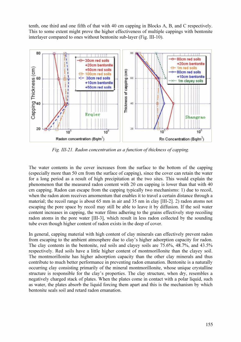
tenth, one third and one fifth of that with 40 cm capping in Blocks A, B, and C respectively.
This to some extent might prove the higher effectiveness of multiple cappings with bentonite
interlayer compared to ones without bentonite sub-layer (Fig. III-10).
Fig. III-21. Radon concentration as a function of thickness of capping.
The water contents in the cover increases from the surface to the bottom of the capping
(especially more than 50 cm from the surface of capping), since the cover can retain the water
for a long period as a result of high precipitation at the two sites. This would explain the
phenomenon that the measured radon content with 20 cm capping is lower than that with 40
cm capping. Radon can escape from the capping typically two mechanisms: 1) due to recoil,
when the radon atom receives amomentum that enables it to travel a certain distance through a
material; the recoil range is about 65 mm in air and 35 nm in clay [III-2]. 2) radon atoms not
escaping the pore space by recoil may still be able to leave it by diffusion. If the soil water
content increases in capping, the water films adhering to the grains effectively stop recoiling
radon atoms in the pore water [III-3], which result in less radon collected by the sounding
tube even though higher content of radon exists in the deep of cover.
In general, capping material with high content of clay minerals can effectively prevent radon
from escaping to the ambient atmosphere due to clay’s higher adsorption capacity for radon.
The clay contents in the bentonite, red soils and clayey soils are 75.6%, 48.7%, and 43.5%
respectively. Red soils have a little higher content of montmorillonite than the clayey soil.
The montmorillonite has higher adsorption capacity than the other clay minerals and thus
contribute to much better performance in preventing radon emanation. Bentonite is a naturally
occurring clay consisting primarily of the mineral montmorillonite, whose unique crystalline
structure is responsible for the clay’s properties. The clay structure, when dry, resembles a
negatively charged stack of plates. When the plates come in contact with a polar liquid, such
as water, the plates absorb the liquid forcing them apart and this is the mechanism by which
bentonite seals soil and retard radon emanation.
155

III-5.4. Migration of radionuclides from the impoundment
Shallow borehole sampling underneath the Erqier uranium impoundment has been conducted
in order to study the infiltration. Uranium, thorium, and radium contents in the solids have
been analysed. The results are shown in Fig. III-10. The average concentrations of natural
radionuclides 238
U, 232
Th, and 226
Ra (area weighted) in soils in the Hunan province are 47.8,
54.2, and 59.4 Bq/kg respectively, with a range of (14.7-431.5), (9.7-437.8), and (20.3-296.8)
Bq/kg respectively. Analytical data of borehole samples indicate that uranium has migrated
downward for about 1.5 m and radium has migrated less than 2 m since 1963. This suggest
that local soils and clays that were used in the bottom liners for the impoundment have
successfully inhibited the radionuclide migration.
Fig. III-22. Radionuclide content in the solids of infiltration beneath the Erqier uranium mill
tailing impoundment.
III-5.5. Vegetation cover and radionuclides analyses in grasses
Samples from grasses planted were collected twice (2 and 4 months after re-vegetation). The
radionuclides (including U, Th, Ra, K) were analysed in the dry mass to evaluate radionuclide
migration from the uranium mill tailings to the vegetation. The same grass species in the
surrounding local environment were also collected and analysed as a reference. Uranium was
analysed by laser-exited fluorescence, Th by colorimetry with spectrophometer, and radium is
analysed by scintillation analysis (radon daughter scintillation detector with active carbon
adsorption). The analytical data are given in Figs. III-12 and III-13.
The vegetation cover on the capping surface is one of the important measures to assure the
long-term stabilisation and isolation of uranium mill tailings. At the Shangrao Site, the
revegetated cover will play an active role to prevent the capping from being eroded due to
high precipitation and to merge remediated tailings into the character of the surrounding
landscape.
156

Fig. III-23. Radionuclide contents in grass and red soil.
The comparison of radionuclides contents in red soil capping and grass is seen in Fig. III-
13(left). The radionuclides contents of 238
U, 232
Th, 40
K are lower than that in red soils; the
226
Ra content is about twice as that in red soils.
157

Fig. III-24. Radionuclide content in grass and comparison with surrounding grass.
The radionuclides in the grass were analysed in order to check whether radionuclides migrate
from the mill tailings. The 238
U content in leaves is about about 2 times (2 months later) and 5
times (4 months later) higher compared to that in the surrounding environment. The 232
Th
content in leaves is about 15% (2 months later) and 1.5 times (4 months later) higher
compared to that in the surrounding environment. The 226
Ra content in leaves is about 7 times
(2 months later) and 8 times (4 months later) higher compared to that in the environment;
while the 40
K content in leaves is about one half (2 months later) and a third (4 months later)
lower compared to that in the surrounding environment (Fig. III-13(right)).
According to field observation, the roots of grasses actually penetrated the capping only down
to about 20 cm. The radionuclide analysis shows that 238
U and 232
Th concentrations in grass
are higher than that in the surrounding soil, which is to some extent related to the mill tailings
underneath. A possible transport mechanism might be capillarity. A similar phenomenon was
reported by American researchers [III-4].
Even there are higher U, Th, and Ra concentration than that in the surrounding soil in both,
the capping soil, and grass sowed, radionuclide concentrations are not higher than the
statistical radionuclide concentration in soils of that province. The concentrations of the
natural radionuclides 238
U, 232
Th, and 226
Ra fall in range of 14.7-431.5, 9.7-437.8, and 20.3-
296.8 Bq/kg respectively, which suggests that no significant migration of radionuclides from
the uranium mill tailings to the environment was detected in this study.
The lower content of 40
K in grass growing on the capping was unexpected. The further
investigation will be conducted to explain this phenomenon.
III-5.6. Cost-effectiveness analyses
With regard to the Erqier uranium mill tailing impoundment, the result of cost-efficiency
analyses is shown in Table III-2. The cost of different capping structures was estimated by
referring to related regulations and prices of the different materials. The cost of the mutiple-
layer capping at Shangrao site is similar to that in Erqier. The efficiency is calculated by
comparison of Rn emanation rate with different capping materials.
158

Table III-2. Cost-effectiveness analysis for multiple-layer capping
Structure Proctor
density
Water
content
Rn emanation
rate [Bq/cm2
·s]Efficiency Cost
80 cm red soils
inter-layered with
20 cm bentonite
1.51 17.0 0.39 +45.8% +18%
100 cm red soils 1.54 16.0 0.72
80 cm red soils
inter-layered with
10 cm benotonite
1.58 16.8 0.56 +22.2% +9%
ACKNOWLEDGEMENTS
The authors are grateful to Mr. Pan Yingjie, Mr. Gao Shangxiong (Division Chief of China
Nuclear Uranium Corporation), and Miss Fu Jin (senior engineer of BRIUG) who provided
technical support. Thanks are also due to Miss Zhang Shuling, Mr. Cai Zhenmin (Division
Chief of the Erqier Uranium Mill), Mr. Wang Jiahe (assistant director of the Shangrao
Uranium Mill) who provided support for in situ testing. Mr. Fu Guoqiang and Mr. Mao (staff
at the Shangrao Uranium mill) and Mr. Liu are thanked for their contribution to field testing.
Professor Dong Wenda from Jiangxi Agriculture University is also thanked for useful
information on vegetation. The International Atomic Energy Agency and CNNC are thanked
for supporting financially the work.
REFERENCES TO ANNEX III
[III-1] LIU, L.-W., GONG, Z.-T., Development and evolution of red paleosols, Marine
Geology & Quaternary Geology, 20 3 (2000) 37–42 (in Chinese).
[III-2] BOSSUS, D.A.W., Emanating power and specific surface area, Rad. Prot. Dosim., 7
(1983) 73–76.
[III-3] MORAWSKA, L., PHILLIPS, C.R., Dependence of the radon emanation coefficient
on radium distribution and internal structure of the material, Geochim. Cosmochim.
Acta, 57 (1993) 1783–1797.
[III-4] RUMBLE, M.A., BJUGSTAD, A.J., Uranium and radium concentrations in plants
growning on uranium mill tailings in South Dakota, Reclam. and Reveg. Res., 4
(1986) 271–277. http://www.fs.fed.us/rm/sd/uranium_radium.pdf
159

ANNEX IV. CZECH REPUBLIC
PREDICTING THE LONG TERM STABILISATION OF
URANIUM MILL TAILINGS
Trojáček
Diamo, S.P., Stráž Pod Ralskem
IV-1. ABSTRACT
The long-term stabilization and remediation of uranium mill tailings ponds is an important
task for DIAMO. After uranium mining was stopped, DIAMO has to remediate more then
400 ha of tailings ponds at three locations. It is currently planned to cover the surface with
low permeability materials with a slope of approx. 3% to protect the interior of the disposal
facility from infiltrating rainwater. This entails to cover the free surface of these ponds with
several hundred thousand tons of inert material. As a result of this load, the porewater from
the tailings is expelled and the body of the impounded materials consolidates. Consolidation
of tailings proceeds irregularly, depending on the internal structure of the tailings layers and
on the progress of loading. The surface needs to be recontoured for a long time into the future.
The topic of the DIAMO project is to predict and optimise the final surface contour of the
tailings pond body, and to determine the time schedule and locations for recontouring work.
The K1 tailings pond in Dolní Rožínka (Southern Moravia) is a typical example for such task.
The average thickness of the tailings layer is around 25 m and the average porewater contents
varies from 25 up to 40%. In the years 1998-99 a PHARE pilot project was undertaken that
aimed to predict the quantity and quality of drainage and infiltration waters as a function of
time.
A new investigation programme (field, laboratory and modelling) has been implemented. The
range of material properties and distribution of types of tailings was established. Orientation
calculations of the tailings consolidation were made for fine slime zone. The results have
shown that significant subsidence of the surface is to be expected after loading with inert
material for the construction of an interim cover.
IV-2. INTRODUCTION
Uranium ore was mined from the Rožná deposit since 1957. A uranium mill is in operation
since 1968 employing a carbonate extraction technology. Two tailings ponds were built as a
repository for mill tailings. Pond K1, the bigger one, is still in operation, while pond K2 is
recently used as a repository for remediation residues. Both ponds are planned to be restored
after uranium production has ceased. A conceptual plan for the restoration of the ponds has
been elaborated [IV-1] as well as the technical plan for their decommissioning [IV-2]. A risk
analysis and environmental impact assessment (EIA) [IV-3] procedure are curently in the
stage of public discussion with the aim to get the final approval from the government
administration no later then at the time of closing of processing plant.
Two different variants for the restoration of the ponds has been proposed. A project
concerning prediction of water balances and water chemistry of the ponds was completed as
part of the PHARE programme ”Remediation Concepts for Uranium Mining Operations in
CEEC – Phase B” [4]. The results obtained within this project were used as the basic criteria
161
J.

for evaluation of restoration variants and for the technical design of various remediation
options.
The CRP project is focused on the prediction and optimizing of final contours of the tailings
pond body and the time schedule and location of remediation work. Validation of the water
balances and predictions of time over which treatment of drainage waters will be required are
integral parts of this project. Field investigations, laboratory testing of undisturbed tailings
samples, long term geodaetic monitoring and mathematical modeling form the elements of
this project.
IV-3. GENERAL DESCRIPTION OF ROŽNA DEPOSIT
IV-3.1.The Rožná Site
The Rožná deposit is located in Southern Moravia, in the Czech-Moravian Highlands, some
55 km North-West of Brno (Fig. IV-1). Uranium mining from the Rožná deposit began in
1957. Uranium ore processing at the Rožná site the commenced in 1968 using a carbonate
leaching method.
BRNO
Fig. IV-25. Location of the Rožná site within the Czech Republic.
IV-3.2. Geology and hydrogeology
The deposit is located in a formation of metamorphic sedimentary/effusive rocks of
Precambrian age, represented mainly by gneisses and amphibolites. Tectonic zones reach up
to 10-15 km in length, their average width is in the order of several metres. Uranium ores
(uraninite and coffinite) are present in depths below 600 m. The uranium mineralisation is of
hydrothermal origin and it is confined to fissure structures. The uranium ores contain a
significant amount of metallic sulfides, namely pyrite.
162

Fig. IV-26. The original contouring in the area of the K1 tailings pond.
Fig. IV-27. View of the tailings pond K1 Rožná – aerial photograph.
163

The K1 tailings pond is located near the shafts nos. R I and R II of the Rožná mine. The
structure of the underlaying rocks is very simple. The underlying rocks, dipping 50° to the
West, consist of gneisses and amphibolites with pegmatite and serpentinite lenses and dykes.
The width of this tectonic zones is about 0.5 m. The metamorphic rocks are covered by
clayey-sandy fluvial sediments. The thickness of the covering sediments varies with a
maximum of up to 4 m. The underlying rocks are largely impermeable. Water is present only
in fractures filled by crushed rock material. The covering sediments are highly permeable.
Subsurface waters drain into Nedvedicka creek.
IV-3.3.Ore Processing
The processing technology is based on ambient pressure carbonate leaching with uranium
separation from the pulp by ion-exchange. Uranium concentrate (yellow cake), containing a
minimum of 65% of uranium, is the final product. The processing plant is located in a
protected water resources zone and, therefore, was required to have a completely closed
process water cycle in order to minimise possible negative influences on the environment.
Two tailing impoundments were built for the disposal of residues: K1 Rožná (built 1965 –
1968) and K2 Zlatkov (built 1978 – 1980). Both tailing ponds were originally of the valley
type (Fig. IV-2), but the K1 pond was later reconstructed with a circumferential dam. The K2
tailing pond is currently not in operation and is used as a repository for remediation residues
(Fig. IV-3).
The K1 pond is still in operation. The dam of this tailings pond is made up from waste rock
without any sealing, heightened step by step from the fifth level with dams 3.5 m of high in
the direction to the central part of the tailings pond. These dams are founded on the deposited
tailings. A basic condition for safe operation of a tailings pond is a minimum horizontal
distance of 15 m between the free water level and a dam made of waste rock alone. A sealing
of the dam body is provided by sedimentation of fine-grained tailings on the inside face of the
dam. The permeability of the dam was calculated from the drainage measurement to be 0.75
m per day (= 8.7×10⁻⁷
m/s). The tailing impoundment is protected against inflow of surface
waters by diverting channels. Seepage waters from the tailings impoundment are collected by
drains and pumped back into the pond.
Table IV-8. Technical parameters of the Rožná K1 tailing pond.
area 64.50 ha
Deposited material 12.8·106
t
volume of free water 1 105 786 m3
volume of deposited material 9.62·106
m3
total capacity 11·106
m3
volume of drained water per year 420 000 m3
max. thickness of deposited material 48 m
max. height of dam 53 m
Taking into consideration the expected close-down of production, a new concept for
heightening of the dams has been implemented. The inner part of the pond was divided by
dams into sedimentation compartments and a water accumulation compartment (the central
part of the tailings pond). Internal dams are running parallel to the circumferential dam at a
distance of 20 m. The space between the dams was filled in with pulp and covered by waste
164
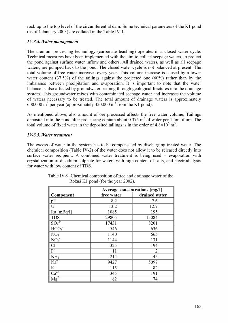
rock up to the top level of the circumferential dam. Some technical parameters of the K1 pond
(as of 1 January 2003) are collated in the Table IV-1.
IV-3.4.Water management
The uranium processing technology (carbonate leaching) operates in a closed water cycle.
Technical measures have been implemented with the aim to collect seepage waters, to protect
the pond against surface water inflow and others. All drained waters, as well as all seepage
waters, are pumped back to the pond. The closed water cycle is not balanced at present. The
total volume of free water increases every year. This volume increase is caused by a lower
water content (37.5%) of the tailings against the projected one (60%) rather than by the
imbalance between precipitation and evaporation. It is important to note that the water
balance is also affected by groundwater seeping through geological fractures into the drainage
system. This groundwater mixes with contaminated seepage water and increases the volume
of waters necessary to be treated. The total amount of drainage waters is approximately
600.000 m3
per year (approximately 420.000 m3
from the K1 pond).
As mentioned above, also amount of ore processed affects the free water volume. Tailings
deposited into the pond after processing contain about 0.375 m3
of water per 1 ton of ore. The
total volume of fixed water in the deposited tailings is in the order of 4.8×10⁶
m3
.
IV-3.5. Water treatment
The excess of water in the system has to be compensated by discharging treated water. The
chemical composition (Table IV-2) of the water does not allow it to be released directly into
surface water recipient. A combined water treatment is being used – evaporation with
crystallization of disodium sulphate for waters with high content of salts, and electrodialysis
for water with low content of TDS.
Table IV-9. Chemical composition of free and drainage water of the
Rožná K1 pond (for the year 2002).
Average concentrations [mg/l ]
Component free water drained water
pH 8.2 7.6
U 13.2 12.7
Ra [mBq/l] 1085 195
TDS 29805 15084
SO4
2-
17431 8201
HCO3
-
546 636
NO3
-
1140 665
NO2
-
1144 131
Cl-
325 194
F-
11 2
NH4
+
214 45
Na+
9427 5097
K+
115 82
Ca2+
345 191
Mg2+
82 74
165

An evaporating unit with a maximum capacity of 210,000 m3
per year was built in 1976. The
treatment unit was complemented with an electrodialysis (EDA) unit of 65,000 m3
per year
capacity in 1984. Since 1976 some 4.9 million cubic metres of water have been treated and
released into the Nedvìdièka creek (on the average 204,000 m3
per year).
The origin of the sulphate ions is to be sought in the oxidation of pyrite during the processing
of the uranium ore. The reaction is not completed in the mill and some residues of that
mineral phase are deposited with tailings into the pond where the oxidation process continues
for a long time. It results in conditions leading to additional leaching of residual uranium in
the tailings.
Comparing the results of the chemical analysis of free and drainage waters shows that the
concentrations of most components proportionally decrease with diluting by clean
groundwater, except for uranium. This indicates that some leaching of residual uranium from
the tailings takes place in deeper layers. It can also be documented in the vertical profile of
chemical composition of the pore water (Table IV-3, Fig. IV-4). While the concentrations of
uranium close to the surface of the tailings correspond very well with free water
concentrations, at a depths between 15 and 25 m they are about 3 times higher, and in the
deepest layers they are up to 7 times higher.
This problem led to a new concept for the water treatment. Beside the two operational
systems, which will be reconstructed for a higher capacity, a third, new system based on
uranium removal from seepage water by ion-exchange will be installed.
0 20 40 60 80 100
51.2 - 51.6
45.4 - 46.8
43.2 - 44.2
41.4 - 42.3
38.9 - 40.2
36.9 - 37.9
34.5 - 35.5
32.9 - 33.9
30.6 - 31.6
28.0 - 28.9
26.4 - 27.4
25.1 - 25.5
22.5 - 24.2
19.8 - 21.3
17.7 - 18.5
15.9 - 16.9
14.0 - 15.0
12.6 - 13.4
10.8 - 11.2
9.2 - 9.8
Dep
th
in
terval [m
]
U [mg/l]
U
Fig. IV-28. Vertical profile of uranium concentrations in pore waters of Borehole KI – 1.
166

Table IV-10. Vertical profile of the chemical composition of pore water in Borehole KI – 1.
depth redox c o m p o n e n t c o n c e n t r a t i o n
sample interval pH potential conductivity TDS NH4 Na K Mg Ca Mo U SO4 HCO3 NO3
number [ m ] [mV] *) [mS/m] [g/l] [ m g / l ] [mg/l]
1-6 8.8 - 9.2 7.89 126 2613 28.20 172.2 6360 144.4 99.0 282.8 3.50 9.9 16970 562.5 890.4
1-7 9.2 - 9.8 7.80 124 2613 27.36 161.4 7780 157.6 96.6 97.1 4.75 7.5 16770 568.2 787.2
1-8 9.8 - 10.8 8.16 107 3118 27.84 216.1 8480 139.4 67.5 48.9 7.06 20.6 17840 1031 829.2
1-9 10.8 - 11.2 7.94 119 2849 27.72 201.8 8340 147.1 86.7 133.5 5.72 11.9 17550 832.9 852.0
1-10 11.8 - 12.6 8.53 127 3022 29.72 195.5 9740 126.3 42.2 19.8 7.06 22.2 18230 1770 860.4
1-11 12.6 - 13.4 8.56 115 3441 34.74 222.8 11770 140.2 33.1 11.3 8.77 23.0 21720 2666 874.2
1-12 13.4 - 14.0 8.67 112 4634 35.72 240.4 11500 152.1 36.0 12.2 8.21 18.6 21920 2603 870.0
1-13 14.0 - 15.0 8.69 56 3516 36.20 264.6 11990 151.9 18.6 6.8 8.44 28.7 22490 3617 576.0
1-14 15.3 - 15.9 8.60 76 3624 35.44 270.4 12470 141.8 21.2 7.2 7.90 24.2 22490 3280 648.0
1-15 15.9 - 16.9 8.68 69 3484 34.14 260.6 12260 142.0 16.0 6.5 7.72 30.3 22300 3399 471.6
1-16 16.9 - 17.7 8.66 67 3452 33.98 268.9 10360 163.8 14.9 8.1 8.04 44.8 21330 3600 206.4
1-17 17.7 - 18.5 8.49 99 3806 39.98 216.1 12340 148.1 31.7 7.8 10.19 63.0 25400 3192 136.8
1-18 18.5 - 19.5 8.48 86 4054 43.66 214.9 14770 145.2 34.7 14.4 10.49 71.1 27730 3058 20.4
1-19 19.8 - 21.3 8.62 76 3925 40.10 304.8 12220 128.5 22.0 14.0 8.52 46.9 25590 3883 26.4
1-20 21.3 - 22.5 8.66 89 4075 39.46 425.0 12770 108.8 20.3 4.3 8.08 78.8 24720 4912 116.4
1-21 22.5 - 24.2 8.60 77 3871 39.46 383.8 12450 123.2 20.7 14.6 8.39 53.5 25210 3970 115.2
1-22 24.2 - 24.8 8.60 94 3989 38.50 473.8 13450 131.5 22.7 8.4 8.54 72.7 24430 4607 404.4
1-23 25.1 - 25.5 8.59 86 3871 39.28 467.4 13700 127.7 21.4 9.4 8.56 76.0 24340 4575 517.2
1-24 25.5 - 26.4 8.59 82 3957 37.96 439.9 12440 131.5 21.2 10.4 8.98 71.1 23760 4165 612.0
1-25 26.4 - 27.4 8.59 95 3806 37.04 489.6 11900 138.8 19.4 10.1 9.11 77.6 22680 4396 868.8
1-26 27.4 - 28.0 8.68 81 3882 37.30 654.7 11120 165.6 17.4 8.1 8.76 83.2 21520 4993 1778
1-27 28.0 - 28.9 8.60 82 4054 38.36 875.4 10790 129.7 18.2 10.0 8.12 100.2 21140 5611 2395
1-28 29.2 - 30.6 8.66 104 3860 39.96 544.8 12370 215.1 24.2 10.3 8.86 68.7 23860 4224 1650
1-29 30.6 - 31.6 8.61 89 3871 38.12 875.9 10950 165.2 21.2 6.3 8.24 103.4 21330 5202 3510
1-30 31.6 - 32.9 8.60 104 3710 34.88 829.5 10930 145.8 18.4 8.5 6.29 89.7 19490 4714 2915
1-31 32.9 - 33.9 8.62 94 3720 33.86 774.9 10400 122.4 15.4 6.3 6.24 92.9 19200 4599 2624
1-32 33.9 - 34.5 8.56 76 3731 33.82 816.1 10480 114.1 23.8 6.1 6.08 101.8 19200 4681 2645
1-33 34.5 - 35.5 8.59 89 3763 33.56 786.0 10690 101.2 15.6 5.9 6.02 103.4 19010 4670 2618
1-34 36.2 - 36.9 8.61 86 3785 34.02 751.4 9860 216.5 14.5 6.8 6.63 79.2 19490 4403 2551
1-35 36.9 - 37.9 8.66 73 3753 33.30 802.4 10020 214.1 14.5 6.0 6.98 92.1 19200 4251 2336
1-36 37.9 - 38.9 8.59 85 3828 33.50 958.0 10950 148.1 16.2 5.9 7.88 98.6 19200 4681 2549
1-37 38.9 - 40.2 8.55 92 3935 34.52 1064.7 9880 135.7 18.2 6.6 8.30 101.8 20070 4669 2232
1-38 40.2 - 41.4 8.57 94 3871 35.20 975.2 11160 169.1 18.2 4.7 7.67 92.9 20170 4470 2677
1-39 41.4 - 42.3 8.57 92 3914 35.86 1022.6 11550 190.5 20.2 5.7 8.19 92.9 20750 4189 2660
1-40 42.6 - 43.2 8.51 104 3957 35.22 946.4 11700 161.2 22.2 6.7 8.02 97.8 20460 4332 2760
1-41 43.2 - 44.2 8.51 110 3882 35.28 866.6 11270 163.8 23.2 5.5 8.15 93.7 20650 4028 2196
1-42 44.2 - 45.4 8.50 103 3871 35.54 860.5 11170 161.4 25.0 6.0 8.28 94.5 20360 4033 2732
1-43 45.4 - 46.8 8.61 84 3796 34.74 724.4 11470 147.7 18.6 4.6 8.06 84.0 19760 4926 2292
1-44 50.2 - 50.9 8.45 94 3473 29.24 609.4 10150 128.8 49.4 8.6 4.79 69.1 16260 4427 1878
1-45 51.2 - 51.6 7.93 98 946 --- 98.5 2800 97.0 54.5 101.8 --- 2.0 5860 461.6 ---
1-47 51.7 - 51.9 8.45 70 1688 --- 83.3 2170 67.7 99.5 123.6 --- --- 8740 2390 ---
*) Pt vs. Ag/AgCl (3M KCl) system
167

IV-3.6.Geotechnical parameters and geodaetic measurements
The geotechnical parameters of the deposited material are the basic data for calculations of
the stability of tailings impoundments. Under the PHARE project., core drilling through the
deposited tailings was undertaken (Fig. IV-5.). Six boreholes (K1-1 to 6) were drilled around
the K1 pond, five of them from the top of the internal dams, and one from the fifth stage of
the main dam. Two types of samples were collected:
(1) samples for the separation of porewaters and the analysis of chemical composition of
both, liquid and solid phases,
(2) undisturbed samples for laboratory tests for geomechanical parameters.
Fig. IV-29. Position of investigation boreholes at Rožná tailings pond K1.
The typical vertical profile of the circumferential part of the pond consists of vertical layers of
coarse-grained ‘sandy’ sediments that are interlayered with fine-grained sludges. This
depends on the former system of deposition. Such vertical profile is usually called a
‘transition zone’. The average values of selected basic parameters for the deposited tailings
are shown in the Table IV-4.
168

Table IV-11. Average values of geotechnical parameters of the Rožná K1 tailing pond.
Paramter Average value Unit
density 1753 kg·m-3
density of dry residue 1183 kg·m-3
moisture content of deposited material 37.5 %
porosity 58.5 %
saturation 97.5 %
permeability of fine-grained layers 6.9 - 7.83 ×10⁻⁸
m·s-1
permeabilty of coarse-grained layers 1.8 - 1.97 ×10⁻⁴
m·s-1
From the beginning of the tailing pond construction on, a geodaetic monitoring of the dam
was undertaken at regular intervals. The vertical, as well as horizontal movements of
geodaetic points located on each additional step of the heightened dam are monitored with
great accuracy every year. The results of this monitoring gives a good idea about the
consolidation of the deposited material during the operation of the tailing pond. Average
vertical movements varied around 10 mm per year, some extreme values reaching up to 20
mm per year. The relatively low consolidation rate of the sludges is caused by the fact that the
process of dewatering of the tailings has not yet started due to the water level in the central
part of the pond being too high. An increase in the consolidation rates is achieved by pumping
out the decant water and starting to load the interim cover material on the top of the pond. The
prediction of the resulting settling process is the main goal of this project.
IV-4. REMEDIATION CONCEPT
The aim of the remediation of both of the tailing ponds is to blend the remediated ponds into
the existing landscape. The remediation involves the dewaterig and treatment of contaminated
waters (free water, porewater, seepage water, drainage water) from the tailings
impoundments. The final goal of the remediation process is to protect the deposited tailings
against infiltration of ambient precipitation, as well as against groundwater inflow. Protection
against direct γ-ray exposure and radon emanation is an integral part of remediation activity.
Two variants of the remediation concept were originally investigated: After evaluation of all
aspects (technical, environmental protection, deep rock protection etc.) and public discussion
the ”A” variant would be implemented.
Variant A - Consecutive removal and treatment of excess free water is assumed in this
variant. A combination of the currently operated treatment technology (evaporation +
electrodyalysis) with ion-exchange for the removal of uranium would be necessary.
Variant B - Quick variant – pumping all free non-treated water into the deepest level of the
Rožná mine after closing down of the mining operation. The currently operated treatment
technology would be applied to the drainage water plus a new technology for uranium
removal.
169

Fig. IV-30. Final contouring of K1 tailings pond. Red numbers indicate elevation or
depression of final contour comparing the situation in June 2002.
The variants differ only in the way in which the free water is managed. The remaining
elements of remediation are the same. The actual remediation will start, therefore, with the
removal of free water. The K1 pond will be stabilised, reshaped and covered with a protective
layer. During this period (approx. 8 – 10 years) the K2 pond will be used as a temporary
reservoir for drainage water. After the covering is completed, a temporary basin will be
constructed on the top of covered K1 pond and remediation of K2 will begin. Finally, both
ponds will be covered with topsoil and be revegetated.
The remediation concept assumes a contouring of the top part of the K1 tailings pond by
infilling the free space with inert material in order to achieve a maximum slope of 3 %. After
lowering the water level in the impounded material, the upper part of the main dam, together
with part of the dewatered tailings will be relocated closer to the middle of the pond with the
aim to achieve an even slope of the impoundment. (Fig. IV-6).
170

After the infilling of the free space is completed, the whole surface of the impoundment will
be covered by a protective layer. Two variants for the construction of this layer with different
materials were investigated.
Preliminary calculations of radiation protection effects and construction requirements (frost-
free foundation) lead to a required thickness of 0.8 m for this protection cover layer. Some
data for different designs of the cover layer together with calculations of the shielding effects
are presented in Table IV-5. The calculations of radiation protection effects were done for two
recommended regulatory limits: 1 µGy per hour for γ-radiation, and 0.8 Bq/m·s for radon
emanation. As can be seen from the results, all suggested cover layers are in compliance with
regulatory limits. The final decision on which type of covering will be used depends on the
actual situation at the time of carrying out of the remediation work. Several factors will affect
this decision, e.g. availability of materials, transport distances, cost etc.
Table IV-12. Selected design variants of cover layer with calculated shielding effect for
each partial layer.
Type of sealing Clay Clay
Type of drainage Crushed rock Synthetic drain
Thickness
[m]
Surface γ dose
[Bq/m2
·s]
Rn emanation
[µGy/h]
Thickness
[m]
Surface γ dose
[Bq/m2
·s]
Rn emanation
[µGy/h]
Recent values - 18 11 - 18 11
Sealing 0.6 0.018 0.034 0.6 0.018 0.034
Drainage 0.15 0.172 0.0122 0.018 0.018 0.034
Cover 0.45 0.0151 0.0005 0.6 0.013 0.0005
Top soil 0.20 0.0143 <0,0005 0.2 0.0117 <0,0005
Type of sealing Synthetic material Synthetic material
Type of drainage Crushed rock Synthetic drain
Thickness
[m]
Surface γ dose
[Bq/m2
·s]
Rn emanation
[µGy/h]
Thickness
[m]
Surface γ dose
[Bq/m2
·s]
Rn emanation
[µGy/h]
Recent values - 18 11 - 18 11
Sealing 0.07 0.36 9.71 0.07 0.36 9.71
Drainage 0.15 0.33 3.47 0.018 0.36 4.95
Cover 0.45 0.26 0.153 0.6 0.26 0.077
Top soil 0.20 0.24 0.038 0.2 0.235 0.019
IV-5. WORK CARRIED OUT DURING THE PROJECT
The specific situation at the Rožná K1 tailings pond poses a significant geotechnical problem
that has to be solved before other remediation works can commence. The prediction of the
consolidation of the deposited material after the surface dewatering and additional loading is
the key issue with respect to the stability of the remediated pond. The successful loading of
infill material will determine the final efficiency of any long term stabilisation and isolation of
the pond because it will determine the success of the planned recontouring of the tailings pond
body.
171

A complex set of field and labratory investigation works has been carried out with the aim to
obtain data on fine slime zone, which is the most important part of the pond for future
remediation. The results from this investigation programme were evaluated in close co-
operation with WISMUT GmbH, using evaluation and modelling tools that have been
developed by that company for the planing and design of tailing ponds remediation.
IV-5.1.Borehole drilling
A new, cored borehole K1-7 (Fig. IV-5) has been drilled from the top of the dividing dam
with the objective to complement currently available data with others from the central part of
the tailings pond. The currently available data do not describe the very fine-grained tailings
located below the free water level. The borehole reached the original surface at a depth of
41.3 m from the top of the dam. The full suite of laboratory investigations on the core samples
was completed, i.e. soil properties, geomechanical, geochemical tests etc. The soil physical
properties were evaluated referring to the major layering of different tailings types. The
typical value ranges of soil physical properties in the identified tailings layers in borehole K
1-7 are shown in the Table IV-5. An analysis of the results shows that the borehole has not
struck the soft (slime) tailings area, but that it was located in the transition zone, i.e. in a part
of the pond, where mixed layers of coarse and fine tailings have been deposited depending on
the distance from discharge points [IV-5].
Table IV-13. Geomechanical properties of major tailings layers from borehole K 1-7
Depth below consistency/ wn e (v.ratio) ρ
s Φ C´ shear vane
surface [m] soil class [%] [g/cm3
] [°] [kPa] strength [kPa]
11 – 13
pulpy/
clay, silty
28-34 0.99-1.07 2.70-2.80 10
13 – 20
(13 – 15,5)
weak to stiff/
silt, clayey, sandy layers
29-42 0.87-1.20 2.78-2.85
25.0 – 31.4
33.8 – 34.5
5 – 22
8 – 15
19-29
20 – 23.4
weak to stiff/
silt, clayey,no sand
40-46 1.18-1.31 2.81-2.84 31.4 5 25
23.4 – 33.3
stiff/
clay, silty
37-44 1.06-1.22 2.81-2.85 29.1 – 29.8 4 – 7 29
33.3 – 41.3
low cohesive/
sand, silty
20-31 0.62-0.83 2.72-2.80 37.3 16 57
IV-5.2. Fine slime sampling below the water level
Since the new borehole did not furnish a typical soft tailings profile, additional sampling of
very fine unconsolidated tailings was undertaken. Using a special device (UWITEC Corer) for
sampling below the water level, a total of five samples were collected. Only one of them (P3),
however, turned out to be suitable for full scale laboratory tests, including the physical soil
properties and oedometer test for the determination of the basic functions e→σ’ and e→k.
The results obtained are typical for unconsolidated fine tailings settling in the fine slime zone
furthest from the discharge point: the void ratio of fine tailings from sample P3 was e1kPa
=
2.65, the respective compression was determined to be Cc= 0.48, the stiffness modulus
increased with loading from 0.1 MPa at 1.25 kPa to 4.5 MPa at a 200-400 kPa additional load.
172

line A
line D
line B
line G
Fig. IV-31. Location of the CPT measurement points except for the body of the dam. Black
contour lines indicate the total thickness of the tailings.
IV-5.3. Identification of fine slimes areas
IV-4.3.1 Cone penetration tests
For the evaluation of the potential settlement process it is necessary to define the occurrence
of mainly fine slime zone. Two indirect methods have been used: (a) cone penetration tests
(CPT), and (b) shear vane tests (SVT). Natural conditions (total depth of free water) and
technical limitations of the devices used only permitted to carry out CPTs to a maximum
depth of 12 m below the tailings surface, and SVTs to 7 m. The tests were undertaken at about
70 points (both for CPT and SVT) in the central part of the pond (Fig. IV-7).
The measured CPT profiles can be grouped into two categories:
173

Type I: profiles showing cone resistance continuously increasing with depth
Type II: profiles showing cone resistance readings significantly varying over depth.
Type I profiles indicate homogeneous material distribution over depth range at the
measurement point. This type of profile mainly occurs along lines E and C and to some extent
along line A; with line E profiles exhibiting a significantly slower increase in cone resistance
with depth than line A profiles. It may be noted that readings along line E and some profiles
along line C define an area of very low cone resistance down to greater depths. In extension
of line E this would also include inner profiles of line F (having a layered structure). Within
the area of measurements, these profiles apparently form a ‘channel’ consisting of very soft
materials.
Profiles showing varying cone resistance (Type II) indicate layered structures within the
tailings deposit. Measuring points along the lines D, G, B and F belong to the Type II. These
profiles were obviously recorded in what is known as ‘intermediate’ zones that comprise
alternating layers of sands and slimes.
Cone resistance distributions calculated from discrete measured values confirm this
assumption. Figure IV-8 shows low cone resistance zones down to greater depths (ca.10 m)
along lines E and C. As a consequence, the slimes deposit is to be expected to occur in these
areas of the tailings pond.
It should be noted that the confidence interval of the calculated distributions is limited to the
centre of the ‘star-shape’ formed by the lines. Structures beyond this area are not based on
these recordings. They have to be interpreted as extrapolation errors as a consequence of
missing measurements. Available CPT data indicate that the slimes zone is mainly located in
the area around line E and around parts of lines C and F.
IV-4.3.2 Shear vane tests
For stability predictions, peak shear strength is of primary significance. The data in the near-
surface area (up to 2 m below tailings upper edge) range from approx. 1 kPa up to more than
20 kPa. This indicates that either very different varieties of tailings or tailings in different
states of consolidation were sampled. Sandy tailings typically exhibit shear strength values in
excess of 5 kPa that rapidly increase with depth. Experience of Wismut GmbH shows that the
shear strength of soft tailings near the surface is less than 5 kPa even after several years of
self-weight consolidation; such situation requires very careful approach to remediation and
cover placement. Figure IV-9 clearly shows two different distributions of depth profiles:
shear strength increase with depth up to values of about 25 kPa (Line C), as well as
very low rise in shear strength distribution (Line E).
Values recorded along lines A, B and C show very low shear strengths of less than 10 kPa
down to a depth of 2 m below the surface. However, the shear strength at these measurement
locations increases significantly with depth.
The shear strength data obtained are in good agreement with CPT results. Low values from
CPTs at measuring points along line E, indicating a relatively homogeneous slime distribution
with depth, are confirmed by very low shear strength values. Shear strengths measured along
line E did not exceed 5 kPa. This is also the case for the three profiles VRF42, VRF62 and
VRF82 located near the platform. These profiles are a direct extension of line E.
174

515 m a.s.l.
518 m a.s.l.
521 m a.s.l.
Fig. IV-32. Interpretation of the CP testing inside the body of tailings. Violet to blue colours
indicates fine slime zone.
175

Line C
y = 3,2391x + 1,0051
R2 = 0,8368
0,00
5,00
10,00
15,00
20,00
25,00
0,00 1,00 2,00 3,00 4,00 5,00 6,00 7,00
depth (m)
VRC10
VRC30
VRC50
VRC80
VRC100
VRC110
VRC120
VRC130
Trend
Line E
0,00
0,50
1,00
1,50
2,00
2,50
3,00
3,50
4,00
4,50
0,00 1,00 2,00 3,00 4,00 5,00 6,00 7,00 8,00
depth (m)
VRE122
VRE162
VRE202
VRE42
VRE82
VRE242
Fig. IV-33. Typical examples of two different types of vertical distribution of shear strength.
Line C – sandy or intermediate zone; Line E – fine slime zone.
The information gained from the assessment of CPT data on the distribution of the slime
deposit mainly around line E is corroborated by the distribution of the SVT values.
No materials characteristic of soft tailings could be obtained from the investigation
programme carried out on samples from boreholes K 1-1 to K 1-7. In earlier Reports [IV-5,
IV-6], the samples from these boreholes were assigned to the tailings beach or transition zone,
respectively. A shallow sample taken in 2002 with an UWITEC Corer exhibits characteristics
that are typical for soft tailings. In the absence of further samples taken at greater depths, it is
assumed that these material properties would also be valid for the underlying tailings. This
assumption is corroborated by results from CPTs that identified soft tailings along line E
down to depths of about 10 metres [IV-6].
IV-5.4.Theoretical and modeling work
Oedometer tests results give the following e→σ’relationship:
176

e= -Cc·log σ’+ e
0 [IV.1]
where Cc = 0.48, and e
0 = 2.65
Conductivity data were derived from samples taken from borehole K 1-7 in the transition
area.. On the basis of the k→e relationship below (Eq. IV.2), a conductivity k of 10-8
m/s is
assumed together with a void ratio e of 2 for the soft tailings area:
k= C·eD
[IV.2]
where C=5×10⁻¹⁰
m/s, and D= 4.5
No void ratio vs. depth profile is available for the soft tailings area. The sample taken with an
UWITEC Corer had a void ratio of e= 2.65. The average void ratio in the soft tailings area
exceeds that one in the transition area around borehole K 1-7 of approx. e= 1.
IV-4.4.1 Modelling of the infilling history
The process of filling and self-weight consolidation was simulated for the locations of the fine
tailings using the non-linear finite strain consolidation model FSCONSOL [IV-7]. The
purpose of this modelling work is (i) to determine representative material functions (e→σ’
and e→kf relationships) for a given tailings type and (ii) to estimate the current degree of
consolidation.
0
5
10
15
20
25
30
35
1 1.2 1.4 1.6 1.8 2 2.2 2.4 2.6 2.8
Void ratio e
Dep
th
[m
]
e(z) in 2002
Fig. IV-34. Modelled void ratio vs. depth due to self-weight consolidation (without additional
load) for the year 2002.
177

The consolidation model requires as input the infilling rate, slurry density (initial void ratio)
and consolidation properties of the tailings (i.e. e→σ’ and kf→e functions). The rate of filling
and initial dry densities of the tailings are estimated from the historic discharge records. Initial
guesses for the non-linear material functions (e→σ’ and kf→e) are taken from the laboratory
analyses.
A deposition time of 34 years (1968 – 2002) is assumed for the thickest tailings deposits of
about 30 m. Deposition rates were already assessed to be 3.5 kg/d·m2
– 4 kg/d·m2
. A 10 years
shorter deposition time for the thinner tailings profiles of about 20 m is assumed.
Applying the functions above to the 30 m thick tailings layer produces the void ratio depth
profile shown in Figure IV-10, which develops due to self-weight consolidation, i.e. without
additional load. The average void ratio is e= 1.8, giving an average hydraulic conductivity of
6.6×10⁻⁹
m/s.
IV-4.4.2 Estimated settlements due to additional loads
The plans for final contouring call for a heightening of the infilling by about 5 to 15 metres in
the area of deep soft tailings layers. The resulting additional load varies from 100 to 300 kPa.
It is assumed that a one metre layer of cover material results in additional load of 20 kPa. In
order to assess load-induced settlements in the soft tailings area, settlements induced by
additional loads of 100, 200, and 300 kPa were calculated for two tailings profiles of 20 m
and 30 m thickness, respectively. From that, relative settlements can be calculated.
Calculation results are listed in Table IV-7. The results indicate that expected relative
settlements are in the range of 8% to 14%, depending on the thickness of tailings and
additional loads.
Table IV-14. Calculated settling of two different tailings thicknesses, due to three
different additional loads.
Additional load [kPa]
100 200 300
Tailings thickness before loading m 21.3
Tailings thickness after loading m 19.3 18.7 18.3
Relative settlement % 9.5 12.3 14.1
Net increase in elevation m 3.0 7.4 12.0
Tailings thickness before loading m 29.6
Tailings thickness after loading m 27.1 26.3 25.8
Relative settlement % 8.3 10.9 12.7
Net increase in elevation m 2.5 6.8 11.3
The lines ‘Net increase in elevation’ in Table IV-7 indicate the actual change in surface
elevation (compared to the year 2002) due to settlement plus the thickness of the additional
load. It may be concluded that a planned thickness of the additional load of about 15 m will
produce a change in surface elevation of approx. 11m. The designed final surface elevation of
542.45 m a.s.l. (Fig. IV-6) would drop to ca. 539 m a.s.l.
178

25.0
25.5
26.0
26.5
27.0
27.5
28.0
28.5
29.0
29.5
30.0
11000 12000 13000 14000 15000 16000 17000
Time [ d]
Ta
ilin
gs
h
eig
ht [m
]
max. additional load
end of
filling
Fig. IV-35. Evolution of the settlement under an additional load of 300 kPa (equivalent to a
15 m cover). It is assumed, that the load increases linearly over one year from 0
to the maximum.
Considering the available materials parameters, any estimate of time evolution of the
settlement will have a high degree of uncertainty. Laboratory tests are needed to determine
conductivities of soft tailings within the relevant area of tailings pond K 1. A rough estimate
is, however, possible: Following the emplacement of an additional of 300 kPa to be
completed within one year, it will take about 2000 days for 90 % of the settlement to be
achieved. This estimate does not take into account measures to accelerate settlement (e.g.
installation of vertical drains). Figure IV-11 illustrates the time evolution of settlements for an
load of 300 kPa. This load was emplaced and uniformly distributed over a period of one year.
In assessing the length of the consolidation phase, it has to be kept in mind that the tailings
pond is still active and there is no indication that the pond will be dormant during a couple of
years afterwards. The calculation was done under the assumption that remediation and fill
placement would begin immediately after the termination of tailings deposition.
IV-6. SUMMARY AND CONCLUSIONS
The currently available information supporting to the remediation concept of the tailings pond
K1 at the Rožná site has been collated. The successful long term stabilisation and isolation of
the pond is a significant geotechnical problem that has to be solved before other remediation
work can commence. A complex set of field, laboratory and modelling investigations has
been completed in order to be able to predict the time and technical progress of remediation of
the pond.
A new concept for the impoundment of tailings will be implemented in the course of the next
few years until the operation of the mill ceases by 2005. The construction of new inner dams
179

have been started to make ‘bridges’ across the pond. The tailings are spread towards the
centre of the pond with aim to cover very fine-grained tailings with sandy (or non-sorted)
materials. This will be a way to achieve a more compact surface over the finest grained
tailings in order to make easier the construction of interim covers after the disposal of tailings
has ended.
The second effect of new progress of impounding is expected in order of partial reducing of
potential settlement process after additional loading of interim cover material. A reduction of
the potential deviation from the designed contours can be achieved by both, reducing the total
thickness of the interim cover layer (i.e. additional load), and transformation of the fine slime
zone into a state close to the intermediate (or transition) zone that exhibits smaller deviations
from the contour as designed.
A secondary effect of the new impounding method is expected in form of a partial reduction
of the potential settlement after additional loading of interim cover material. A reduction of
the potential deviation from the designed contours can be achieved by both, reducing the total
thickness of the interim cover layer (i.e. additional load), and transformation of the fine slime
zone into a state close to the intermediate (or transition) zone that exhibits smaller deviations
from the contour as designed.
Some additional investigations are envisaged after the impoundment of tailings has ended. It
will be necessary to drill a new borehole from the top of one inner dam into the central part of
the pond. The purpose is to obtain a full vertical profile for deriving geotechnical properties,
namely for the function void ratio vs. permeability. This will then be the basic information for
modelling of the progress with time of settlement process.
REFERENCES TO ANNEX IV
[IV-1] DIAMO, ”Remediation concept for the tailing ponds, o.z. GEAM Dolní
Rožínka”, Prague (1994)
[IV-2] DIAMO, ”Uranium mining and milling close-down programme at Rožná deposit,
technical project o.z. GEAM Dolní Rožínka”, DIAMO s.p., Dolní Rožínka
(1996).
[IV-3] DIAMO, ”Environmental impact assessment for o.z. GEAM Dolní Rožínka
operations”, Dolní Rožínka (1998).
[IV-4] C&E / WISMUT GmbH, Phare Multicountry Envirnmental Programme: Tailings
Ponds Remediation Plannig / contract 98-0170.00. Pilot Project ”Development of
the Tailings Pond Water Balance”, Final Report PP CZ 98 – SDD 07, Chemnitz,
Germany (1999).
[IV-5] WISMUT GmbH, ”Compilation and Analysis of Selected Geotechnical Data of
the Rozna K1 Tailings Pond”, Wismut GmbH, Chemnitz (2002).
[IV-6] WISMUT GmbH, ”Assessment of the state of consolidation of the soft tailings
zone of Tailings Pond Rozna K1”, Wismut GmbH, Chemnitz (2003).
[IV-7] GWP SOFTWARE, “FSCONSOL User‘s Manual”, GWP Software Inc., London,
ON, Canada (1999).
180
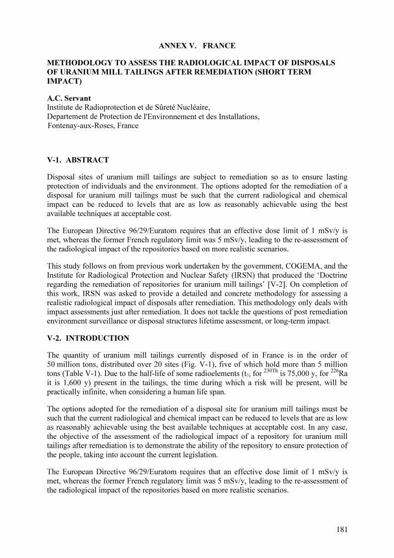
ANNEX V. FRANCE
METHODOLOGY TO ASSESS THE RADIOLOGICAL IMPACT OF DISPOSALS
OF URANIUM MILL TAILINGS AFTER REMEDIATION (SHORT TERM
IMPACT)
A.C. Servant
Institute de Radioprotection et de Sûreté Nucléaire,
Departement de Protection de
V-1. ABSTRACT
protection of individuals and the environment. The options adopted for the remediation of a
disposal for uranium mill tailings must be such that the current radiological and chemical
impact can be reduced to levels that are as low as reasonably achievable using the best
available techniques at acceptable cost.
The European Directive 96/29/Euratom requires that an effective dose limit of 1 mSv/y is
met, whereas the former French regulatory limit was 5 mSv/y, leading to the re-assessment of
the radiological impact of the repositories based on more realistic scenarios.
This study follows on from previous work undertaken by the government, COGEMA, and the
Institute for Radiological Protection and Nuclear Safety (IRSN) that produced the ‘Doctrine
regarding the remediation of repositories for uranium mill tailings’ [V-2]. On completion of
this work, IRSN was asked to provide a detailed and concrete methodology for assessing a
realistic radiological impact of disposals after remediation. This methodology only deals with
impact assessments just after remediation. It does not tackle the questions of post remediation
environment surveillance or disposal structures lifetime assessment, or long-term impact.
V-2. INTRODUCTION
The quantity of uranium mill tailings currently disposed of in France is in the order of
50 million tons, distributed over 20 sites (Fig. V-1), five of which hold more than 5 million
tons (Table V-1). Due to the half-life of some radioelements (t½ for
230Th
is 75,000 y, for 226
Ra
it is 1,600 y) present in the tailings, the time during which a risk will be present, will be
practically infinite, when considering a human life span.
The options adopted for the remediation of a disposal site for uranium mill tailings must be
such that the current radiological and chemical impact can be reduced to levels that are as low
as reasonably achievable using the best available techniques at acceptable cost. In any case,
the objective of the assessment of the radiological impact of a repository for uranium mill
tailings after remediation is to demonstrate the ability of the repository to ensure protection of
the people, taking into account the current legislation.
The European Directive 96/29/Euratom requires that an effective dose limit of 1 mSv/y is
met, whereas the former French regulatory limit was 5 mSv/y, leading to the re-assessment of
the radiological impact of the repositories based on more realistic scenarios.
181
Fontenay-aux-Roses, France
Disposal sites of uranium mill tailings are subject to remediation so as to ensure lasting
I'Environnement et des Installations,
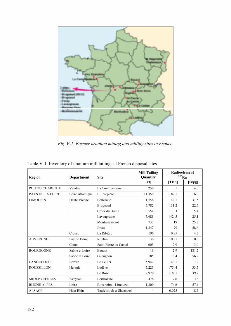
Fig. V-1. Former uranium mining and milling sites in France.
Table V-1. Inventory of uranium mill tailings at French disposal sites
Mill Tailing
Quantity
Radioelement
226
RaRegion Department Site
[kt] [TBq] [Bq/g]
POITOU CHARENTE Vendée La Commanderie 250 1 4.0
PAYS DE LA LOIRE Loire Atlantique L’Ecarpière 11,350 182.1 16.0
LIMOUSIN Haute Vienne Bellezane 1,556 49.1 31.5
Brugeaud 5,782 131.2 22.7
Croix du Breuil 554 3 5.4
Lavaugrasse 5,681 142. 5 25.1
Montmassacrot 737 19 25.8
Jouac 1,347 79 58.6
Creuse La Ribière 196 0.85 4.3
AUVERGNE Puy de Dôme Rophin 30 0.31 10.3
Cantal Saint Pierre du Cantal 605 7.9 13.0
BOURGOGNE Saône et Loire Bauzot 16 2.9 181.2
Saône et Loire Gueugnon 185 10.4 56.2
LANGUEDOC Lozère Le Cellier 5,947 43.1 7.2
ROUSSILLON Hérault Lodève 5,223 175. 4 33.5
Le Bosc 2,970 118. 1 39.7
MIDI-PYRENEES Aveyron Bertholène 476 7.6 16
RHONE ALPES Loire Bois noirs – Limouzat 1,300 74.6 57.4
ALSACE Haut Rhin Teufelsloch et Shaentzel 4 0.025 18.5
182

The following sections describe the previous methodology used for the radiological impact
assessment of uranium mill tailings repositories, as it was practiced since 1990, and some of
its results (Section V-2). The the lack of realism for the critical group and the lowering of the
dose limit to 1 mSv/y led to a review of this methodology (Section V-3). Its application to the
Lodève site is a good opportunity to appreciate the expected consequences of reducing the
effective dose limit (Section V-4).
V-3. PREVIOUS FRENCH PRACTICE
V-3.1. Methodology
Authorization to close a mining site and management of uranium mill tailings repositories
were governed particularly by the French Decree no. 90-222. This decree introduced the
principle of added exposure, or the Annual Added Exposure Rate (French acronym TAETA)
that corresponded to the difference between the Annual Exposure Rate due to repository after
remediation (TAETfinal
) and the natural Annual Exposure Rate before it was operated
(TAETinitial
). This natural exposure is due to in particular the presence of natural radioactive
substances on the site and in its immediate vicinity.
External exposure Internal exposure
Inhalation Ingestion
[ ] [ ] [ ]g2
b10U
Bq7000
bRa
mJ6
dt10PAE
mJ2
dt10PAE
Bq170
10tDust
mSv5
10tATAET
32382266Rn2206Rn222
36
××+×+×××+×××+××+××= −−−−−
TAETA = TAET TAETfinal initial
−
A : γ dose rate (nGy. h-1
)
[Dust] : long-life alpha emitters (mBq.m-3
)
PAE : radon Potential Alpha Energy (nJ.m-3
)
[226
Ra] : Volumic activity of 226
Ra (Bq.l-1
) in water
[238
U] : Concentration of 238
U (mg.l-1
) in water
t : Exposure time (7000 hours per year)
d : Inhalation rate of man (0,8 m3.
h-1)
b : Water ingestion per year (2,2 l.d-1
x 365 day = 803 l)
Bq : Becquerel, equivalent to one disintegration per second
J : Joule, for radon Alpha Potential Energy (EAP) in nJ (10-9
J)
Gy : Gray, absorbed dose, quantity of energy (J) absorbed by 1 kg of material
Sv : Sievert, radiance effect on the living tissue
Fig. V-2. TAETA calculation.
The calculation of TAETA was applicable to the most exposed persons, fixing exposure
parameters (quantity of ingested water, inhaled air, time spent on the site). The radiological
impact on the environment was considered to be acceptable when the TAETA for members of
the public was less than 1, which corresponded to an added effective dose of 5 mSv.
Adding for each exposure pathway the ratio of the corresponding value of added exposure
over a year and the annual limit (Figure V-1) allowed calculating the TAETA. The annual
limits were defined as follows:
183

5 mSv for external exposure;
170 Bq for long-lived alpha emitters in the 238
U-chain, present in inhaled dust
suspended in air;
2 mJ of potential alpha energy for short-lived decay products of inhaled 222
Rn;
7 kBq for ingested 226
Ra;
2 g for ingested uranium, the daily quantity of hexavalent compounds that can be
ingested not exceeding 150 mg.
The Decree 99-222 defined a critical group by the following characteristics:
exposure times: 7000 h/y;
inhalation rate: 0.8 m3
/h;
ingestion over 365 days of 2.2 l/d of water as sampled in the receiving watercourse
immediately below disposals.
V-3.2. Available evaluations
The order of magnitude of the added effective doses for the main French tailings repositories
that have been evaluated using this methodology is summarized in Table V-2 and Fig. V-3.
All these evaluations remain below 5 mSv/y and meet the requirements of Decree 90-222.
Table V-2. Order of magnitude of effective added doses corresponding to a scenario of the
type as defined in Decree 90-222, for a critical group under the immediate
influence of the main uranium mill tailings repositories [V-1]
SiteExternal
exposure
Exposure by
inhalation
Exposure by
ingestion
Effective dose
from the natural
environment
Added
effective dose
[mSv/y] [mSv/y] [mSv/y] [mSv/y] [mSv/y]
Bertholène 0.9 0.8 0.9 1.6 1.0
Bessines 1.7 1.6 0.2 2.7 0.8
L’Ecarpière 1 0.7 0.2 1.5 0.4
Forez 1.4 1.3 0.2 1.9 1.0
Le Cellier 1.5 0.6 0.3 1.8 0.6
The relative uncertainty of these results is generally around 30% due to the large variability of
measured values of the radon activity per unit volume and the external exposure.
The limit of 1 mSv appears to be met. However, it should be noted that these calculations
ignore the uncertainties mentioned above.
The new methodology detailed in Section V-3 mainly introduces the definition of realistic
population groups and exposure scenarios that makes it possible to assess radiological impacts
of uranium mill tailings repositories more objectively with regard to radiological protection
objectives.
184

Bertholène
Bessines
L'Ecarpière
La Commanderie
Forez
Le Celier
0.9 0.8 0.9
1.7 1.6 0.2
1 0.7 0.2
1.6 1 0.4
1.4 1.3 0.2
1.5 0.6 0.3
1.6 1
2.7 0.8
1.5 0.4
2.6 0.4
1.9 1
1.8 0.6
0 0.5 1 1.5 2 2.5 3 3.5 4
External exposure Inhalation Ingestion
Natural effective dose Added effective dose
[mSv per annum]
Bertholène
Bessines
L'Ecarpière
La Commanderie
Forez
Le Celier
0.9 0.8 0.9
1.7 1.6 0.2
1 0.7 0.2
1.6 1 0.4
1.4 1.3 0.2
1.5 0.6 0.3
1.6 1
2.7 0.8
1.5 0.4
2.6 0.4
1.9 1
1.8 0.6
0.9 0.8 0.90.9 0.8 0.9
1.7 1.6 0.21.7 1.6 0.2
1 0.7 0.21 0.7 0.2
1.6 1 0.41.6 1 0.4
1.4 1.3 0.21.4 1.3 0.2
1.5 0.6 0.31.5 0.6 0.3
1.6 11.6 11.6 1
2.7 0.82.7 0.8
1.5 0.41.5 0.4
2.6 0.42.6 0.4
1.9 11.9 1
1.8 0.61.8 0.6
0 0.5 1 1.5 2 2.5 3 3.5 4
External exposure Inhalation Ingestion
Natural effective dose Added effective dose
External exposureExternal exposure InhalationInhalation IngestionIngestion
Natural effective doseNatural effective dose Added effective doseAdded effective dose
[mSv per annum]
Fig. V-3. Annual doses and dose contributions at selected sites.
V-4. CURRENT METHODOLOGY FOR SHORT TERM IMPACT ASSESSMENT
V-4.1. Data collection
The description of the environment of the site and the site itself is the basis of the impact
assessment. All the parameters of the environment that can possibly influence the result of the
impact calculation should be examined.
V-3.1.1 The environment at the site
Local meteorological conditions
It is necessary to know accurately the climatic processes that will govern the atmospheric
dispersion of dust and radon.
A wind frequency distribution as well as rainfall records should be provided.
All the data must be representative of an average year and should be established from data
accumulated for several years.
Moreover, all exceptional events (particularly rain events) have to be compiled properly so as
to take into account their influence on the water management.
It is of course necessary that all the data are collected at the site or from a point in the nearby
environment.
185

Geology- hydrogeology
A detailed description of the local geology should be provided, as well as relevant data for the
hydrogeology. All information that could help the understanding of groundwater movements
should be provided. If a local groundwater model is available it should be presented.
Hydrographical system
Detailed descriptions of the various watercourses that cross the site should be presented. The
flow (particularly floods and low water) of the watercourses, as well as drained surfaces,
catchment areas, civil engineering features, and tributaries should be mentioned.
Water uses
Domestic and agricultural uses of water have to be clearly known and described. Possible uses
for aquaculture, leisure, or tourism should also be described, if relevant.
Agricultural environment
Local cultivations, animal husbandry, and other activities linked with food production have to
be described. Soil use is important to describe, as well as the origin of irrigation water.
Fishing and aquaculture activities should be described if relevant.
Description of the human environment
Demographic data have to be supplied for the area subject to the impact of radioelements.
These data should deal not only with the settlement but also with working populations and
other populations (school-children, tourists…).
V-3.1.2 Site description
Description of the wastes
All potential sources of radioactivity have to be listed. For each radioactivity source,
quantities, mass activities, physical and chemical stabilization treatments, mineralogy, and
geochemistry have to be described.
Disposal structures- remediation options
The repository structures as well as the remediation options have to be described and their
durability should be discussed.
Water management on the site
Water management objectives are to organize a selective collection of contaminated and non-
contaminated water, and the prevention of erosion. The various systems used as well as their
efficiency and durability have to be described.
Various workings on the site
A precise list of the various installations on the site (open pits, underground mines, waste
rocks dumps) that may interact with the repository has to be developed.
V-4.2. Development of the site conceptual model and exposure pathways
V-4.2.1. Conceptual model
A conceptual model is a discursive and graphical representation of the situation. It represents
a synthesis of the knowledge acquired on the site and its surroundings, and with respect to the
environmental vulnerability.
186

The model helps to understand and to explain the situation in terms of contamination sources
and actual as well as potential populations exposures pathways. Figure V-2 shows an example
of a model representation using compartments.
groundwater
resuspension
fishery
products
inhalation external exposure ingestion
MAN
intrusion scenarios
/ occupational exposures
Source
radon
exhalation
reuspension
atmosphere
soil wells surface water
sedimentcattlecrops
groundwater
resuspension
fishery
products
inhalation external exposure ingestion
MAN
intrusion scenarios
/ occupational exposures
Source
radon
exhalation
reuspension
atmosphere
soil wells surface water
sedimentcattlecrops
Fig. V-4. Example for the conceptual model.
V-4.2.2. Exposure pathways
External exposure
External exposure comes from particles deposited and from the radiations emanating from the
site, radiation emanating directly from the site being generally highly predominant. It can be
calculated using a measured average dose rate.
Internal exposure via inhalation
Internal exposure due to inhalation of short-lived daughters of 222
Rn and 220
Rn is a major
pathway. It is calculated from the data on the volume potential alpha energy concentrations of
short-lived daughters of 222
Rn and 220
Rn in the atmosphere. Dust coming from the site can
also contribute to the internal exposure via inhalation, which is calculated using the volume
activity due to long-lived alpha emitters in the dust in suspended in the atmosphere.
187

Internal exposure via ingestion
Contaminated water used for irrigation or watering animals can be a major contamination
source. Ingestion of foodstuffs contaminated by the use of contaminated water is an internal
exposure source. Contamination drinking water should also be taken into account, whether it
comes from a well or from the distribution system, even if it may be a very secondary
pathway.
V-4.3. Development of population groups and scenarios
V-4.3.1. Location of population groups
The objective is to determinate the geographic location of the inhabited area, residents of
which receive the highest impact from the mining area under study. Since the inhabited areas
around the site are generally large, it will be necessary to use a rationalised method.
V-4.3.2. Composition of population groups
The chosen groups have to be representative of the exposure of the whole surrounding
population. The higher the impact is, the detailed the assessment should be, and the most
refined the selection of population groups has to be.
People in a population group can be either adults or children, but in any one group, people
should belong to the same age group. There is no methodology to determine a priori, i.e.
before measurements in the environment and dose calculation are undertaken, which specific
age group should be adopted. Actually, even if dose coefficients for the various age groups
are well known, the result of the added dose calculation depends on
activity schedules;
frequented places;
consumption of locally produced food;
radioelements concentrations in the various consumed produces
Therefore, it is not possible to leave out any age group before a complete calculation of the
added effective dose has been undertaken and it has been demonstrated that the level of
exposure of this group is negligible compared to other groups.
V-4.3.3. Scenario definition
The attempt to be realistic, in accordance with Article 45 of the European Directive
96/29/Euratom, will lead to a determination of scenarios corresponding to real local lifestyles.
In order to perform a realistic assessment, activity schedules have to be as close as possible to
the life and habits in the local environment at the site. Data concerning food consumption
have to be given and should be accompanied by as many statistical data as possible. The
origin of the food-stuffs has to be known in detail, in particular where they are cultivated
locally.
When determining the diets for each population group, it is necessary to take into account the
age group, the self-sufficiency level, and if possible the professional activity, the place of
residence, etc.
188

V-4.4. Measurements in the environment
Radiological impact assessment immediately after remediation can be based on the
monitoring network installed by the operator or by the authorities in the nearby environment.
This network also allows to check the evolution of the source term.
The measurements have to be tailored to the exposure pathways that have been identified and
to the local lifestyles.
V-4.4.1. Location of measurements and analysis
Outdoor measurements
These measurements concern the mean external exposure dose rate, the Potential Alpha
Energy (PAE) of 222
Rn and of 220
Rn, and long-lived alpha emitters in suspended dust.
Measurements have to be made at the site at all the places, where contaminanted residues are
disposed of, and if possible at a place on the site, where there is no disposal of contaminated
residues.
In the nearby environment measurement stations should be installed at all locations inhabited
by the population groups, and at all locations, where the population groups work and
undertake leisure activities.
Measurements inside buildings
These measurements concern the Potential Alpha Energy (PAE) of 222
Rn and of 222
Rn.
Necessary measurement locations on the site are existing buildings that are or that could be
used for other professional activities.
In the nearby environment measuring stations should be installed in some houses of the
population groups, in some buildings where the respective people work (farms, schools…)
and in some leisure buildings (gymnasium….).
Water
Sampling for analysis has to be carried out in catchment areas for agricultural use, at
consumer taps, and if relevant in the swimming and fishing areas.
Food chain
The radionuclides to be analysed include at least: 238
U, 230Th
, 226
Ra, 210
Po, and 210
Pb.
Sampling has to be done in gardens, on fields, and in greenhouses, from products bought
locally, and, if relevant, where e.g. wild fruit and mushrooms are gathered.
The objective is to get at least over a whole study year an averaged data set for the external
exposure dose rate every quarter, an average value for PAE of 222
Rn and of 220
Rn, and
monthly values for the activity of long-lived alpha emitters in the suspended dust. For
drinking water, monthly concentration value for each radionuclide over the study year, and
one concentration value for each radionuclide and each type of food locally produced, should
be determined.
189

V-4.4.2. Presentation of results
Reporting should include:
the location of the measurement, or of the sampling point, or of the cultivation, if it is a
processed food product;
a description of the measuring station (distance to the mining area, location on the wind
rose, local topography, presence or absence of a ‘shield’ (e.g. a hill) between the site
and the station, location with regard to the hydrological situation at the site);
the sampling period;
the climatic parameters that can influence the result;
all the parameters that are used to transform the result of measurements into usable
concentrations or dose rate (for example water content, sampled air volume).
V-4.5. Background radiological level
‘Natural’ radioactivity that comes from cosmic and telluric radiation.
If there is detailed information on the radiological state of the area before the beginning of
mining operations, it can be used as background level. However, often environmental data are
not precise enough and cannot be used. Some measurement stations should then be installed
in the natural surroundings, in order to get some relevant data not influenced by the site.
Such stations have to be installed in a geological context similar to the geological context of
the site, upwind and upstream the mining site, and on drinking water distribution systems
different from those used by the studied population groups.
The objective should be to develop for each measurement station at the site a reference station
in nearby environment that is representative of the natural surroundings.
V-4.6. Site impact calculation
Impact assessment is based on the determination of the total added effective dose resulting
from the exposure of the various identified population groups. It corresponds to the difference
between the current effective dose and the effective dose estimated for the initial situation.
V-4.6.1. Dose coefficients
Dose coefficients enable to relate incorporated quantities (through ingestion or inhalation) and
effective doses. They depend on the age group. Dose coefficients that have to be used are
issued in the European Directive 96/29 Euratom.
V-4.6.2. Sensitivity analysis – uncertainty
Generally a number of parameter are only imprecisly known play an important part in the
dose assessment. Therefore it is necessary to estimate the uncertainty in the dose calculations.
The impact studies require an estimation of the uncertainty associated with the dose
calculation results. Although a complete uncertainty analysis is not necessary, there must be
undertaken a concise uncertainty analysis based on a sensitivity analysis of the parameters
that highly influence the calculated doses, in particular those that have the highest uncertainty.
190

This process is necessary in order to be able to assess the highest possible dose received by
population groups.
V-4.7. Determination of reference group(s) and monitoring networks
Population groups that receive the highest impact from a site are considered to be reference
groups. Reference groups are monitored afterwards to ensure that the site impact remains
acceptable.
If a population group with different lifestyle and habits is noticed afterward (for example after
the building of new houses near the site, or a new camp site…), it is necessary to monitor its
environment and make a calculation of the added effective dose in order to check if it could
be a new reference group.
V-5. APPLICATION TO THE LODÈVE SITE
Lodève is a former uranium mining and milling site where production was stopped in April
1997; site remediation was completed in 2001. A four-person team operates the water
treatment station, which processes water from the flooded mines and the uranium mill tailings
impoundment, and it conducts environmental monitoring activities. The team also monitors
and maintains the former production areas of the site, which will be converted into industrial
zones in the near future.
Two methodologies were applied in the assessment of the radiological impact of the Lodève
site in 2001 [V-3].
The first one was based on the scenario described in Decree 90-222 and the second one was
based on realistic scenarios as described in Table V-3.
Table V-3. Description of the scenarios – time spent in various places [h/y].
Scenario 1 Scenario 2 Scenario 3 Scenario 4 Scenario 5
Time spent
[h/y]
Adult
working far
from the site
Retired
people
Adult
working
near the site
– agriculture
Adult
working
near the site
– office
Adult
working on
the site –
office
Decree 90-
222 scenario
Inside the house or at
the office located near
the site
5000 4380 5000 7200 5000 -
Outside near the site 1160 3980 3360 1160 1560 7000
Far from the site 2200 - - - - 1360
Walking on the site 400 400 400 400 400 400
At the office,
on the site - - - - 1800 -
The results (Table V-4) show that:
the TAETA for the scenario according to Decree 90-222 and for all the locations of
population groups is lower than 1;
191

the added effective dose calculated for all the realistic scenarios and all the locations of
population groups is lower than 1mSv/y.
Table V-4. Radiological impact assessment for the Lodève site for an adult – comparison
between methodologies
Added effective dose [mSv/y]
(European Directive 96/29)
Location of
population groups TAETA
(Decree
90-222) Scenario 1 Scenario 2 Scenario 3 Scenario 4 Scenario 5
Saint-Julien 0.18 0.45 0.68 0.64 0.54 0.90
Saint Martin 0.18 0.46 0.69 0.66 0.55 0.91
Mas Lavayre 0.09 0.31 0.41 0.40 0.35 0.74
Capitoul 0.07 0.28 0.36 0.35 0.31 0.70
Mas Campagnard 0.20 0.41 0.74 0.68 0.45 0.87
Ferme de Treviels 0.20 0.43 0.74 0.69 0.50 0.90
les Hémies 0.09 0.27 0.40 0.38 0.30 0.71
However, TAETA close to 0.2 corresponds to an added effective dose close to 1 mSv/y.
Application of the new methodology allows a better understanding of the short-term impact
and a better choice of future reference groups. In fact, the added effective doses of adults not
working on the site are less than 0.8 mSv/y. Closer attention has to be paid on adults working
on the site (e.g. monitoring of the indoor air radon concentration).
V-6. CONCLUSIONS
The new radiological impact assessment methodology for impoundments of uranium mill
tailings after remediation allows to demonstrate the ability of the repository to ensure
protection for people, taking into account the current legislation.
In addition, through this impact study, reference groups, which are population groups that
receive the maximum impact from the site, can be defined. Exposure pathways related to
reference groups will be monitored afterwards to ensure that the site impact on man remains
acceptable.
Moreover the impact study helps to define a monitoring network that aims to ensure that the
impact on the environment remains acceptable.
It is essential to remember that the impact on man has to be re-assessed when population
groups with different lifestyles are noticed afterwards (e.g., after the construction of new
residences near the site, or a new camp site), or when the monitoring of the environment
shows significant changes in the measured parameters values.
192

REFERENCES TO ANNEX V
[V-1] METIVIER H., “L'Uranium, de l'environnement à l'homme", EDP Sciences,
collection IPSN, Fontenay-aux-Roses (2001) 336. (in French).
[V-2] INSTITUT DE RADIOPROTECTION ET DE SÛRETÉ NUCLÉAIRE, “Doctrine
regarding the remediation of repositories for uranium mill tailings”,
IPSN/DPRE/SERGD note No. 99/42, (1999) (in French).
[V-3] INSTITUT DE RADIOPROTECTION ET DE SÛRETÉ NUCLÉAIRE, “Expertise
du dossier d’arrêt définitif des travaux et d’utilisation des installations minières sur la
concession du Lodévois (Appraisal of the Lodève industrial site remediation file)”,
IRSN/DPRE/SERGD report No. 02/01, (2002) (in French).
193

ANNEX VI. GERMANY
DEVELOPMENT OF TECHNOLOGIES FOR IN SITU REMEDIATION OF
CONTAMINATED SITES BY DIRECTED FORMATION OF NATURALLY
OCCURRING SLIGHTLY SOLUBLE MINERALS
G. Ziegenbalg
TU Bergakademie Freiberg , Institute of Technical Chemistry, Freiberg, Germany
VI-1. ABSTRACT
A novel technology is described that allowes the in situ treatment of areas contaminated by
heavy metals or radionuclides, as well as the sealing of porous rock or soil formations.
Solutions supersaturated with respect to sparingly soluble minerals (e.g. sulfates, carbonates,
hydroxides) are prepared and used as a grout or penetration agent. Precipitation processes take
place during the flow of such solutions through the treated soil or rock formation. These lead
to an immobilisation of contaminants and a decrease in the permeability of the formation.
Promising grouts are gypsum- or BaSO4-forming solutions, as well as systems leading to the
formation of CaCO3. The results of the first large scale application of solutions leading to
directed BaSO4 formation in the former uranium mine Königstein of Wismut GmbH
(Germany) are summarised.
VI-2. INTRODUCTION
Up to now, only a limited number of remediation technologies are known that allow a cost
effective in situ treatment of soils, tailings or waste rock contaminated by heavy metals. In
many cases, pump-and-treat methods are applied. Soil flushing, encapsulation and excavation
followed by decontamination or disposal are other techniques used to remediate contaminated
areas. All these techniques are extremely expensive and require long times. In some cases,
secondary processes are induced, resulting in an additional release of contaminants. On the
other hand, many natural processes are known that lead to the formation of sparingly soluble
minerals. Such phenomena are typically coupled dissolution/precipitation processes. A well
known method to reduce the acidity of tailings is overlaying with alkalinity generating
materials such as limestone, dolomite or fly-ash. Dissolution of these materials, for example
by rain, leads to alkaline solutions that can neutralise acidic zones. As result, secondary
minerals such as iron or aluminium hydroxide and gypsum are formed. They can plug the
flow paths and thus deeper zones are protected against oxidation and leaching. Similar
reactions occur, when acid mine drainage penetrates into CaCO3 containing soil formations.
Dissolution as well as precipitation processes take place. It is well documented that the
formation of gypsum and of hydroxides can result in clogging of flow paths [VI-1–VI-3].
Further solution transport is interrupted and infiltration of acid mine drainage is stopped.
Although gypsum is characterised by a relatively high solubility, long-time stable sealing has
been proven. Natural mineral forming processes require, however, long times and only small
amounts of mass are transported. If new ways for in situ immobilisation processes to
remediate areas polluted by heavy metals or radionuclides are sought, utilisation of processes
similar to those occurring in nature is seen as a promising way.
Two different scenarios have to be taken into consideration:
195

(1) Immobilisation of dissolved contaminants, for instance radionuclides in pore water;
(2) Fixation of soluble or oxidisable contaminants, for instance protection of sulfidic
minerals against leaching.
Although in many cases the same chemicals can be used, there are substantial differences
between these two tasks. The hydraulic properties of porous formations are the main cause for
this. It is rather difficult to achieve a homogenous mixing of two solutions in soils or porous
rock formations. Mainly plug flow is induced and mixing takes place only in boundary layers.
In the case of grouting, a special arrangement of injection and extraction holes is necessary.
Under the second scenario, inter alia, the dissolution of heavy metal containing compounds
must be prevented, i.e. the source term must be immobilised. Both, a reduction of the
permeability of the acid generating domains, and the protection of reactive mineral surfaces
against oxidation and leaching are possible ways to reduce the release of contaminants.
In all cases, the main aspect to be considered is, whether long-term immobilisation of the
contaminants can be achieved. Particularly, the formation of sparingly soluble minerals is of
importance in this context. Depending on the nature and the concentration of the
contaminants, the formation of hydroxides, sulphates, carbonates or phosphates can be taken
envisaged for the fixation of radionuclides and heavy metals.
First attempts to prevent the generation of acidic rock drainage by covering of reactive
mineral surfaces with insoluble phosphates were described by Evangelou and Zhang [VI-4].
The concept of ‘Neutral Barrier Technology’ involves two procedural steps [VI-5]: First, the
formation is permeated with a saturated Ca(OH)2 solution. In the second step, gaseous CO
2 is
injected. The calcite precipitates formed plug the flow paths and can also act as a reactive
barrier. However, only small quantities of dissolved Ca(OH)2 can be brought into the
formation due to the low solubility of lime.
The objetive of the current project that is summarised here is to artificially induce
precipitation processes thus reducing the permeability of soils, or immobilising contaminants.
Metastable solutions are prepared that lead to the formation of sparingly soluble minerals,
such as sulfates, carbonates or hydroxides.
VI-3. Possibilities to prepare mineral forming solutions
The utilisation of crystallisation/precipitation processes similar to those occurring naturally is
only possible, if solutions can be prepared that lead to a directed formation of sparingly
soluble minerals. This means, that the solutions have to contain in dissolved form the
components of those minerals that are intended to be formed. Mineral formation then should
take place during the passage of the solution through the formation that is being treated. There
are different ways to prepare such solutions. Depending on the properties of the intended
minerals, their respective solubility, and the quantities of solids required, the following
options are possible [VI-6,VI-7]:
Preparation of supersaturated solutions by using precipitation inhibitors;
Preparation of supersaturated solutions by addition of compounds leading to a
temporarily enhanced solubility;
Construction of reactive systems. Solutions are prepared that contain components which
release ions that then form insoluble minerals (for example carbonates) or that cause a
change in the pH value.
196
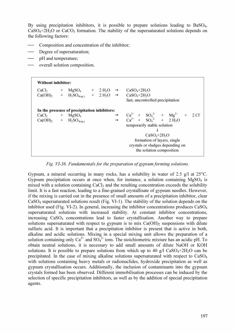
By using precipitation inhibitors, it is possible to prepare solutions leading to BaSO4,
CaSO4×2H
2O or CaCO
3 formation. The stability of the supersaturated solutions depends on
the following factors:
Composition and concentration of the inhibitor;
Degree of supersaturation;
pH and temperature;
overall solution composition.
Without inhibitor:
CaCl2
+ MgSO4 + 2 H
2O � CaSO
4×2H
2O
Ca(OH)2 + H
2SO
4(aq.) + 2 H
2O � CaSO
4×2H
2O
fast, uncontrolled precipitation
In the presence of precipitation inhibitors:
CaCl2
+ MgSO4 � Ca
2+
+ SO4
2-
+ Mg2+
+ 2 Cl-
Ca(OH)2 + H
2SO
4(aq.) � Ca
2+
+ SO4
2-
+ 2 H2O
temporarily stable solution
�
CaSO4×2H
2O
formation of layers, single
crystals or sludges depending on
the solution composition
Fig. VI-36. Fundamentals for the preparation of gypsum forming solutions.
Gypsum, a mineral occurring in many rocks, has a solubility in water of 2.5 g/l at 25°C.
Gypsum precipitation occurs at once when, for instance, a solution containing MgSO4 is
mixed with a solution containing CaCl2 and the resulting concentration exceeds the solubility
limit. It is a fast reaction, leading to a fine-grained crystallisate of gypsum needles. However,
if the mixing is carried out in the presence of small amounts of a precipitation inhibitor, clear
CaSO4 supersaturated solutions result (Fig. VI-1). The stability of the solution depends on the
inhibitor used (Fig. VI-2). In general, increasing the inhibitor concentrations produces CaSO4
supersaturated solutions with increased stability. At constant inhibitor concentrations,
increasing CaSO4 concentrations lead to faster crystallisation. Another way to prepare
solutions supersaturated with respect to gypsum is to mix Ca(OH)2 suspensions with dilute
sulfuric acid. It is important that a precipitation inhibitor is present that is active in both,
alkaline and acidic solutions. Mixing in a special mixing unit allows the preparation of a
solution containing only Ca2+
and SO4
2-
ions. The stoichiometric mixture has an acidic pH. To
obtain neutral solutions, it is necessary to add small amounts of dilute NaOH or KOH
solutions. It is possible to prepare solutions from which up to 40 g/l CaSO4×2H
2O can be
precipitated. In the case of mixing alkaline solutions supersaturated with respect to CaSO4
with solutions containing heavy metals or radionuclides, hydroxide precipitation as well as
gypsum crystallisation occurs. Additionally, the inclusion of contaminants into the gypsum
crystals formed has been observed. Different immobilisation processes can be induced by the
selection of specific precipitation inhibitors, as well as by the addition of special precipitation
agents.
197

0
1
2
3
4
5
6
7
0 100 200 300
time [h]
Ca
lciu
m co
nce
ntra
tio
n [g
/l]
Inhibitor A
Inhibitor B
Inhibitor C
Inhibitor D
Fig. VI-37. Course of gypsum crystallisation from oversaturated solutions depending on the
inhibitor concentration
Fig. VI-38. Gypsum crystals formed in porous sandstone
198

0
10
20
30
40
50
60
70
80
90
0 25 50 75 100 125 150
time [h]
Ba2+
-con
cen
tra
tio
n [m
g/l]
inhibitor A
inhibitor B
inhibitor C
inhibitor C
inhibitor D
without inhibitor
Fig. VI-39. Course of BaSO4 precipitation from oversaturated solutions (inhibitor
concentration: 0.8 mg/l)
Fig. VI-40. BaSO4 layers formed on sandstone.
These grouting solutions can penetrate even into microfractures and very small pores. Already
single gypsum crystals can cause a significant permeability reduction. They block flow paths
and make further solution transport impossible. Solutions with a high stability can be used for
treating areas far away from the point of injection. This is especially useful for achieving a
large radius of injection and for ensuring a long life time of the injection point. Gypsum
199

crystallisation leads to a step by step closure of flow paths in a manner similar to naturally
occurring cementation processes.
In many cases a single injection will not be sufficient to achieve a closure of flow paths in a
given case. Repeated injections may be necessary, leading to a step-by-step closure of flow
paths, as precipitates form on the walls of the pore spaces. Such stepwise closure of open
pores ensures a better depth penetration of the grouting solutions than could be achieved when
pores would be closed completely at once. Figure VI-3 shows gypsum crystals grown within a
porous sandstone. The crystals are strongly connected with the surrounding rock. Due to a
blocking of the flow paths, further solution transport becomes impossible.
0
50
100
150
200
250
300
350
400
450
0 200 400 600 800
time [h]
CaC
O3 [m
g/l]
without inhibitor
5 mg/l inhibitor
25 mg/l inhibitor
Fig. VI-41. Course of CaCO3 precipitation from oversaturated solutions
BaSO4(s) forming solutions can contain up to 500…600 mg BaSO4/l in dissolved form. This
seems to be low in comparison with gypsum producing solutions, but one has to remember
that the natural solubility of BaSO4 is only 2.5 mg/l. This means, however, that solutions with
concentrations more than 200 times above the natural BaSO4-solubility can be prepared.
Normally, mixing of Ba2+
and SO4
2-
containing solutions leads to a spontaneous precipitation
of BaSO4 (Fig. VI-4). Very fine crystals are formed that settle slowly. Due to the extremely
low solubility product of 10-10
mol2
/l, even traces of Ba2+
ions are precipitated in the presence
of SO4
2-
ions. This reaction is used in analytical chemistry as a highly accurate method for
SO4
2-
determination. Mixing of BaCl2 and sulfate ions containing solutions in the presence of
an inhibitor allows to prepare clear, BaSO4-supersaturated solutions. A favoured way to
prepare ‘pure’ BaSO4 solutions is to use Ba(OH)2 solutions and dilute H2SO4 as starting
components. Apart from the inhibitor the resulting grout contains only Ba2+
and SO4
2-
- ions,
and no further components that are brought into the process have to be taken care of. A third
way to prepare BaSO4 forming solutions employs Na2SO3. The sulfite ion can be converted
into sulphate by oxygen and thus, other oxidation processes are stopped. As a result, reducing
conditions are created. The action of the BaSO4 grouts is similar to that of CaSO4 solutions.
Decomposition of the inhibitor results in the formation of insoluble BaSO4 precipitates. These
precipitates form a protective layer on surfaces, including reactive minerals, and further
dissolution is prevented (Fig. VI-5). An immobilisation of soluble contaminants is achieved
200

by fixation in a mineral with a high stability under most naturally occurring conditions. It is
possible to control the speed of the crystallisation process through the composition of the
inhibitor and its concentration, or by the absolute degree of supersaturation.
formation of layers
formation of single
crystals
precipitation as result
of mixing with present
pore water
Fig. VI-42. Action of mineral forming
solutions.
Fig. VI-43. Column experiments.
In a similar way it is possible to prepare CaCO3 forming solutions by mixing of Na2CO3 and
CaCl2 solutions (Fig. VI-6). These are able, as discussed already for BaSO4 and gypsum
forming solutions, to form layers protecting reactive surface, to block flow paths or to
immobilise dissolved contaminants (Fig. VI-7).
VI-4. Immobilisation of heavy metals by using BaSO4-forming solutions
VI-4.1.Results of laboratory investigations
Column experiments with both, freshwater and BaSO4-forming solutions, were used to
investigate the differences between flushing and immobilisation. The columns used had a
length of 1000 mm and a diameter of 300 mm, and were filled with approximately 60 kg of
rock material from the Königstein mine (Fig. VI-8). A volume of approximately 23 l was
required to fill the columns to the top. The solutions or water, respectively, were pumped
from the bottom up at an average rate of 1.2 l/d. After filling, the columns were flushed
continuously by water or immobilisation solution. After certain times the flow was stopped
and the columns were emptied completely. The material remained in contact with air for up to
half a year. After that, washing with water was started again. The immobilisation tests were
carried out with a solution resulting in the formation of 350 mg/l BaSO4. At an inhibitor
concentration of 80 mg/l the stability was in excess of 96 hours. In order to increase the
immobilisation capacity, small amounts of sodium silicate were added. Technical grade
Ba(OH)2×8H2O, Na2SO3, and sodium silicate solution were used. The feed solution was
prepared in batches step by step by mixing solutions of the separate constituents. An alkaline
and reducing solution was obtained. In the case of mixing with acidic, heavy metal containing
solutions precipitates of slightly soluble hydroxides or hydroxysulphates were formed,
depending on the mixing ratio.
201

0
10
20
30
40
50
60
2.9 22.10 11.12 30.1 21.3 10.5
date
Mn
, U
, N
a, M
g [m
g/l]
0
50
100
150
200
250
Ca
, Z
n [m
g/l]
Mn
Mg
U
Na
Zn
Ca
Flushing with
water
Fig. VI-44. Development of effluent concentrations during flushing of the column with water
(the flushing was interrupted after 5 days, and continued after 45 days and 6 months
respectively).
0
2
4
6
8
10
12
14
16
18
27.10 16.12 4.2 26.3 15.5
date
U, A
l, C
u [m
g/l]
0
20
40
60
80
100
120
140
Ca
, Z
n [m
g/]
Cu
U
Al
Zn
Ca
flushing with water
immobilisation
with BaSO4-
solutions
Fig. VI-45. Development of effluent concentrations during and after immobilisation with
BaSO4-forming solutions.
202

Figure VI-9 shows the concentrations of selected constituents during the flushing of the
column with water. It is clear that concentrations decrease only slowly with time. Long flush
times, or high volumes of water, are required to reduce the concentrations of metals in the
effluent. Contact with air induces oxidation processes. As result, the second or third washing
step also produces solutions with high contaminant concentrations. In contrast, the application
of BaSO4-forming solutions leads to effluent solutions with rapidly decreasing concentrations
(Fig. VI-10). Four weeks after permeation with BaSO4-forming solutions, the column was
also flushed with water. Effluent concentrations remained at a low level. Obviously, oxidation
processes were prevented due to the formation of insoluble layers consisting of BaSO4,
hydroxides and other secondary minerals. The same was observed during a second flushing
with water, five months later.
VI-4.2.Results of field tests in the former uranium mine Königstein of Wismut GmbH
The application of solutions supersaturated with respect to BaSO4 was tested in the former
uranium mine ‘Königstein’ of Wismut GmbH (Germany). In this mine, uranium was
recovered inter alia by in situ leaching of the sandstone host rock with dilute H2SO4. A
detailed description of the mining operations carried out at Königstein is given in [VI-8]. The
mine borders on to the National Park Saxon Switzerland and the distance to the river Elbe is
600 m only. The ore body is located in the so-called 4th
sandstone aquifer, the deepest of four
hydraulically separated aquifers in the cretaceous basin. The 4th
an 3rd
aquifer are separated by
a 10 to 30 m thick aquitard that is perforated by natural faults and man-made connectivities
due to the mining activities. The 3rd
aquifer is an important groundwater resource for the
region and of high environmental and economical significance.
Uranium production started in the 1960s employing conventional underground mining. Due to
decreasing ore contents, a step by step switch over to specially developed underground in situ
leaching technologies was carried out. One leaching technology used is based on ‘hydrostatic’
or infiltration leaching of blasted low-permeability rock in hydraulically isolated blocks.
These blocks had volumes in the range of 100,000 to 1,000,000 m3
. In order to construct such
blocks, sections of the ore containing horizon were blasted and then separated by dams from
the other mine area. The blocks were leached with a solution of 2 to 3 g/l H2SO4. During the
in situ leaching period, altogether 130,000 t of sulphuric acid were brought into the mine.
Additionally, an unknown amount of sulphuric acid due to pyrite oxidation was released
within the mine. All this has resulted in a substantial change of the geochemical status of the
deposit. A high level of mobile contaminants is present in the mine, consistion of mainly
sulphate, heavy metals, and natural radionuclides.
Uranium mining was stopped in 1990. Since that time, the closure of the mine was prepared.
A step-wise, controlled flooding will be carried out over the next few years. In order to
prevent the spreading of contaminants, and in particular the contamination of the 3rd
aquifer
due to rising water levels, a control and collection system for the flooding waters has been
constructed. The collected water is pumped to the surface and treated in a dedicated water
treatment plant. Due to the high content of mobile and leachable contaminants, the occurrence
of contaminated water is expected for long times. From an ecological, as well as an
economical point of view, it is very important to reduce the time by which the applicable
water standards can be met, and to minimise the amount of discharged contaminants. In situ
immobilisation by applying BaSO4 forming solutions was investigated as one possible
alternative for reducing the total amount of contaminants released, as well as limiting the time
over which this occurs.
203

A ‘block’ situated in the southern part of the mine was selected for the field test. The block
was leached in the 1980s, after that, no further treatment was carried out. It was shown that it
is possible to prepare without problems large quantities of BaSO4 forming solutions under
conditions typical for mining. Over a period of six days a total of 3,540 m3
BaSO4 forming
solution was brought into the block. The average solution composition was 115 mg/l SO3
2-
and 200 mg/l Ba2+
. 300 mg SiO2 were added as sodium silicate solution. Approximately 1,200
kg BaSO4 could be formed. The solution was characterised by an extremely high stability. In
the absence of suspended solids, no precipitation occurred within 120 hours.
0
50
100
150
200
250
300
350
400
Al Fe U Zn
dis
ch
arg
ed
a
mo
un
ts [kg
]
1. Immobilisation
2. Immobilisation
flushing with
water
Fig. VI-46. Total amount of contaminants discharged during the various stages of the field
test.
The solution remained for ten days in the block. After that time, the solution drained with a
initial volume flow of 20 m3
/h. In a second step, the block was filled again with the BaSO4
forming solution. After draining once more, the block was flushed with freshwater in order to
demonstrate the stability of the neoformed secondary minerals.
The amounts of contaminants discharged during the different treatment periods are
summarised in Figure VI-11. A step by step reduction is visible. The first immobilisation has
resulted in solutions containing a total of 11.6 kg uranium, 363 kg iron and 101 kg zinc. After
the second treatment with BaSO4 forming solutions, a total output of only 8 kg U, 184 kg Fe
and 52 kg Zn was observed. The flushing of the treated block with freshwater did not lead to
an increased discharge of contaminants. To the contrary, a further reduction of the total load
was observed. This demonstrates the stability against leaching of the immobilisates.
Otherwise a drastic increase should have been observed.
To assess the effectiveness of the immobilisation, it is necessary to compare the discharged
amounts of contaminants with those that would be expected when washing the test field with
water. The results of a flushing experiment on a block located close to the test site were the
basis for such calculations. During this experiment, the block was filled with water and
emptied several times. Based on the results obtained, it was possible to predict the expected
development of contaminant concentrations in the case of flushing the test field with water.
Figure VI-12 shows the development the U concentrations when flushed with water and after
204

0
5
10
15
20
25
30
0 10 20 30 40 50 60 70 80 90 100
collected solution [%]
Ura
n [m
g/l]
Uranium
concentration after
immobilisation
uranium
concentration in
the case of flushing
with water
Fig. VI-47. Comparison of the change in effluent uranium concentrations after immobilisation
and for flushing with water only.
0
5
10
15
20
25
30
35
1. Immobilisation 2. Immobilisation
discharged uranium
[kg]
uranium discharged
after immobilisation
discharged uranium in
the case of flushing with
water
Fig. VI-48. Comparison of the amounts of discharged uranium in the case of immobilisation
and for flushing with water only.
205

Fig. VI-49. View of the grout plant used for the preparation of the BaSO4 forming solution.
the first immobilisation with BaSO4 solution. The main difference is that theimmobilisation
has resulted in a significant drop of the concentrations, whereas a washing would produce
solutions with slowly decreasing concentrations only. The effect of the immobilisation is
visible not only in the development of the concentrations, but also in the total amounts of
discharged contaminants. For both immobilisation stages the discharged amounts of
contaminants are between 50 and 70% lower than would be expected in the case of flushing
the block with water (Fig. VI-13).
VI-4.3.Large scale application
Based on the results from these field tests, the decision was taken to apply this newly
developed technology to selected areas of the Königstein mine. Approximately 100,000 m3
of
BaSO4 forming solutions were prepared and injected between December 2001 and May 2002
into three different blocks. The blocks were prepared for uranium leaching before 1990, but
the operation was suspended when uranium mining was terminated. As the rock had been in
contact with air and moisture for more than 10 years, flooding would cause the formation of
highly concentrated acidic solutions. Treatment with BaSO4 forming solutions was aimed at
inhibiting oxidation processes and reducing contaminant discharge during the flooding
process at a later stage. As in the test fields, the solution was based on Ba(OH)2, Na2SO3,
water glass, and a precipitation inhibitor. Figure VI-14 gives an impression of the grouting
plant used. Ba(OH)2 solutions were mixed within a pipe with water and an the inhibitor-
sodium-sulfite-sodium-silicate solution. In this way, up to 50 m3
/h of supersaturated solution
could be prepared. Samples taken from different locations in the blocks demonstrated the
successful use of BaSO4 forming solutions.
206

VI-5. SUMMARY AND CONCLUSION
The use of mineral forming solutions offers many possibilities to immobilise contaminants in
permeable formations. Both, the protection of reactive mineral surfaces against oxidation or
leaching, and the immobilisation of dissolved contaminants is feasible.
The application of BaSO4-silica forming solutions is regarded as a promising approach to
immobilise heavy metals in situ within porous formations, for example in former in situ
leaching areas. BaSO4 and silica layers covering reactive mineral surfaces, as well as
secondary precipitates, such as hydroxides or hydroxysulfates are formed. Because of the
extremely low solubility of barytes, long-term stable immobilisation is achieved. Trouble-free
preparation of BaSO4 forming solutions is feasible under field conditions [VI-9,VI-10].
The technology of sealing and immobilisation by controlled crystallisation processes can find
many applications, both for the remediation of contaminated areas and for solution of
geotechnical problems. The technology combines many advantages such as:
Sealing and immobilisation is achieved exclusively by naturally occurring minerals. The
immobilisation process typically is coupled with a permeability reduction;
There are many options to direct the precipitation of the minerals and thus to control
sealing and immobilisation;
Different technologies such as spraying, penetration grouting, pressure grouting,
infiltration from ponds or reservoirs, can be used to transport the mineral forming
solutions into the area that is to be treated;
All grouts or penetration agents are pure solutions with a viscosity similar or equal to
natural groundwaters. A good penetration or infiltration even of soils with a low
permeability is obtained;
The treatment with mineral-forming solutions can be combined with other remediation
technologies, such as soil flushing or pump and treat processes;
It is possible to construct reactive barriers within polluted areas by an in situ technique.
The applicability of directed crystallisation processes to immobilise contaminants in tailings
depends on the characteristics of the tailings itself. In all cases in which an exchange of the
porewater is possible, the use of supersaturated solutions offers the possibility to fix soluble
components and to overlay reactive surfaces with insoluble minerals of a high stability. If the
consistency of the tailings is so that grouting or infiltration, for example from trenches, is
impossible, crystallisation processes can be used to encapsulate the tailings. In other words,
the migration of heavy metal containing plumes can be prevented by sealing of potential flow
paths.
Possible applications of the technology developed might include the remediation of rock
formations treated by acidic as well as alkaline in situ leaching techniques and inhibition or
reduction of acid rock or mine drainage. The technology is environmentally friendly and is
easily adaptable to local conditions.
207

REFERENCES TO ANNEX VI
[VI-1] Rammlmair, D., Hard pan formation on mining residuals, In: MERKEL, B.J.,
PLANER-FRIEDRICH, B., WOLKERSDORFER, C., Uranium in the Aquatic
Environment (Proc. Mining and Hydrogeology III, 15–21 September 2002,
Freiberg) Springer, Berlin etc. (2002) 173-182.
[VI-2] BLOWES, D. W., REARDON, E. J., CHERRY J. A., The formation and potential
importance of cemented layer in inactive sulfide mine tailings, Geochim.
Cosmochim. Acta, 55 (1991) 965–978.
[VI-3] CHERMAK J. A., RUNNELS, D.D., “Self-sealing hardpan barriers to minimize
infiltration of water into sulfide-bearing overburden, ore and tailing piles”, Tailings
and mine waste`96 (Proc. Internat. Conf. Tailings and Mine Waste, Fort Collins,
Co., USA) Balkema, Rotterdam etc. (1996) 265–73,
[VI-4] EVANGELOU, V.P., ZHANG, Y.L., A review: Pyrite Oxidation Mechanism and
Acid Mine Drainage Prevention, Critical Rev. Environm. Sci. Technol., 25 2 (1995)
141–199.
[VI-5] WARING, C.L., TAYLOR, J.R., “A new technique for building in-situ subsurface
hydrologic barriers: NBT”, In: FERNÁNDEZ RUBIO, R. (Ed.), International Mine
Water Association: Mine, Water & Environment (1999) 663–665.
[VI-6] ZIEGENBALG, G., “In-situ remediation of heavy metal contaminated soil or rock
formations and sealing of water inflows by directed and controlled crystallization of
natural occurring minerals”, In: FERNÁNDEZ RUBIO, R. (Ed.), International
Mine Water Association: Mine, Water & Environment (1999) 667–672
[VI-7] ZIEGENBALG, G., “Zur Anwendung von Kristallisationsprozessen für die Lösung
von geotechnischen Aufgaben und zur Schadstoffimmobilisierung in Gesteinen”,
Beiträge zur Kristallisation anorganischer Stoffe aus Lösungen, Freiberger
Forschungsheft A 853 (HOLLDORF, H., VOIGT, W., Eds.), TU Bergakademie
Freiberg (1999)
[VI-8] TONNDORF, H., Die Uranlagerstätte Königstein, Bergbau in Sachsen, Vol. 7,
Landesamt für Umwelt und Geologie, Sächsisches Oberbergamt Freiberg (2000).
[VI-9] ZIEGENBALG, G., SCHREYER, J., JENK, U., Feldversuche zur
Schadstoffimmobilisierung in gelaugtem Quadersandstein, Glückauf
Forschungshefte, 64 1 (2003) 18–23
[VI-10] ZIEGENBALG, G., SCHREYER, J., JENK, U., PÄTZOLD, C., MÜLLER, E., In-
situ Schadstoffimmobilisierung in der Grube Königstein der Wismut GmbH.
Glückauf Forschungshefte 64 2 (2003) 53–59.
208
ANNEX VII. KAZAKHSTAN
DEVELOPMENT OF METHOD OF COVERING RAISING DUST BEACHES OF
RADIOACTIVE WASTES STORAGE OUT OF OPERATION
A. Gagarin
Ulba Metallurgical Plant PJSC, Ust-Kamenogorsk, Kazakhstan
VII-1. ABSTRACT
“Ulba Metallurgical Plant’ PJSC (Ulba) is an enterprise with more than 50 years of history of
manufacture of different products involved in the nuclear fuel cycle. These activities entailed
the construction of various tailings pond for the storage or disposal of processing sludges.
The design of such ponds usually assumes a balance between tailings input and water
evaporation so that the material remains moist at all times during the operational period.
However, after a significant reduction of the production volumes at Ulba a lowering of the
free water level in the waste storage pond occurred. The extent of the lowering of the water
level is in the order of metres and the area of ‘beaches’ formed as a consequence is in the
order of hectares. The drying out of these beaches gives rise to contaminant dispersal due to
wind erosion.
This project investigated various methods for stabilising the beaches, thus protecting against
wind erosion, preventing the infiltration of atmospheric precipitation, and providing a certain
mechanical durability. Materials investigated for forming covering or cementing layers were
water glass (Na-silicate), clays, cement, magnesium carbonate, magnesium oxide,
combinations of these components, as well as organic polymers. A particular problem was the
applicability on geomechanically very unstable, semi-liquid surfaces.
Also discussed is the need for and feasibility of relocating the tailings.
VII-2. INTRODUCTION
The ‘Ulba Metallurgical Plant’ PJSC (Ulba) is an enterprise with more than 50 years of
history of manufacture of different products involved in the nuclear fuel cycle. At different
times there were products of thorium oxide, natural U3O8, enriched uranium dioxide fuel for
VVER and RBMK reactors of Russian design, and nuclear fuel from reprocessed uranium. In
addition, for a long time Ulba has been producing beryllium metal based materials and
products. At present, Ulba is a single facility with the complete cycle of beryllium production
from ore concentrates to finished products of beryllium and its alloys and compounds.
All these production processes were designed in such a way that during the long period of
their operation liquid waste has been collected in special storage ponds. Figure VII-1 shows
the layout of Ulba’s disposal pond system.
209

Pond 1 - 3
Pond 1
Pond 1с
Volume: 1.680E+6
Status: decommissioned
Status: decommissioned,
under administrative control
Status: under construction
Most Vulnerable to Failure
Facility Perimeter
Roadways
Liquid Effluent Waste
Covered / Capped Solid Waste
Revegetated/Reclaimed Lands
Withdrawn Land Buffer
Wells (and well number)
Direction Off-site
Groundwater Flow Direction
(water table is 9 to 30 m below the
ground surface)
m3
Volume: 1.183E+6 m3
Status: decommissioned
Volume: 2.447E+6 m3
Status: decommissioned
Emergency Evacuation Route
Pond 2
Pond 3
Legend:
ULBA METALLURGICAL PLANT DISPOSAL PONDS
Loam
Pond 3
Pond 1-3
Pond 2Pond 1
Pond 1с
backfilled with gypsum
498Б
498А
Greenhouse
710
Building 616
30
31
32
33
34
35
36
37
40
38 39
1
41
2А
2
3
13
2
7п 29
26
North
To
Ulba
River
3.2
km
Towatersupplywells8.2km
Region-wide Solid Radioactive
Waste Disposal FacilityToIrtyshRiver5.4km
f
D
o
s
t
i
-
un
R
o
h
fDve
c
r
i
i
n
Quarry
Building 480, Locker Room
Towatersupply
wells7.0km
Emergency Lumber
Supplies Towatersupplywells
3.7km
Fig. VII-50. Ulba Metallurgical Plant disposal ponds
Fig. VII-51. Pond No. 1
210

Fig. VII-52. Beach formation at Ponds No. 1-3.
Currently, two waste storage ponds, pond No.1 and pond No.2, are in use. Pond No.1c was
taken out of service and re-cultivated in the 1970s by covering it with a thick layer of clay. At
present, pond No.1-3 is not used due to the malfunctioning of its bottom liner. Pond No.3 is a
new waste storage pond that is under construction. The depth to the groundwater underneath
the pond is 9-30 m. The distance from the pond to the town water supply wells is 3.7 – 7.0
km, that to Irtysh river 5.4 km and that to Ulba river 3.2 km. The Figure VII-1 also shows the
groundwater monitoring wells.
Figure VII-2 is an image of the currently used pond No. 1. As can be seen, the water balance
is intact. The balance between waters discharged into the pond together with the waste,
atmospheric precipitation input, and evaporation rate at the pond surface are monitored
regularly. The calucalated balance indicates that no water losses from the tailings pond into
underlying aquifer occurs.
211

After the drastic drop of production outputs due to the end of the cold war and disintegration
of the Soviet Union in th 1990s, the quantity of liquid waste disposed into the ponds was
reduced drastically. It resulted in a draw-down of water level in one of the ponds and
formation of beaches from the production waste slurries. It has been noted that the water level
dropped by about 5 metres resulting in the formation of beaches with an area of about 5 ha.
Fig. 3 shows images of the pond where beaches have been formed.
The composition of the beach material is very complex. The material contains radioactive
particles, toxic compounds of beryllium, as well as thorium and uranium. There is an
imminent danger of atmospheric contamination due to the wind erosion of the beach material.
The increase of beryllium concentrations and volume activity in the air in the pond area in the
periods of higher winds was repeatedly noted.
Various ways of suppressing windblown erosion and dust generation were investigated by
cementing or coating the beaches. This problem of forming coatings at the beaches is both,
very critical and urgent, and at the same time very complicated. The main problem is to
develop a process of coating that can be deployed on these instable and gel-like materials.
A multiple layer cover was envisaged that would be deployed in a stepwise fashion.
VII-3. RESULTS OF THE WORK
VII-3.1. The impounded material
Development of suitable cover compositions has started with studies of the chemical
composittion of the ‘beach’ sediments, i.e. the impounded material. Four representative
samples of the sediment from different locations on the ‘beaches’ were taken. A special metal
tube with a spiral drill was used for sampling of the sediment profile to 1 m depth. The bulk
chemical composition of the dry sample is given in Table VII-1.
Table VII-15. Bulk chemical composition of the dry 'beach' sediments
Composition of dry sample [%] Sample
No.Ca Mg Al Fe Si SO
4
2-
Be
Water
content [%]
1 16.0 20.8 5.0 1.0 8.4 21.3 0.01 28.9
2 15.7 14.8 6.1 1.6 9.7 21.2 0.01 13.3
3 12.1 8.07 1.4 0.67 21.2 28.35 0.2 42.1
4 25.2 14.6 0.5 1.7 3.3 20.1 0.2 50.1
The chemical analyses indicated a quite high inhomogeneity of the ‘beach’ sediments, but this
is not surprising considering the wide variety of materials disposed off during the principal
production phases of the facility. This inhomogeneity means that it will be hardly possible to
use the sediments as a component of any layer of the cover. If the cover material were
developed on the basis of a sample taken at one location of the ‘beach’, one may obtain quite
unacceptable results for other parts of the ‘beaches’ where the sediment composition does not
correspond to the initial sample. As a first stage, a solidifying compound for the surface layer
or the sediment was developed. Different binding and filling materials were tested, such as
212

water glass (Na-silicate), clays, Portland cement, magnesium carbonate, and magnesium
oxide. Tests were performed by placing a layer of the material to be tested on a layer of the
sediment taken from a ‘beach’ of the storage pond. The depth of penetration of the test
material into the sediment was estimated visually together with the appearance of the surface
layer after drying. Experimental results are given in Table VII-2.
Table VII-16. Experimental results of solidifying liquid process waste sediments
No. Cover material to be tested
Penetration into
the surface layer
Surface layer appearance after
drying
1
Clay water suspension
(Solid:Liquid= 1:1)
No
Clay layer is cracking irrespective
of thickness (0.5-1.5 cm)
2 MgO water suspension (S:L= 1:1) No
Strong setting of MgO layer free
of cracks
3
Water suspension of a clay-sand mixture (1
part clay + 2 part sand + 1 part water)
No No cracks at layer thickness 2 cm
4
Water suspension of fine ground MgCO3
(S:L= 2:1)
No No cracks in MgCO3layer
5
Water glass (Na2O×mSiO
2, m = 2.7) density
= 1.15g cm-3
Complete Strong layer
6
Water glass (Na2O×mSiO
2, m = 2.7) density
= 1.39g cm-3
Complete Smooth and strong layer
7
Suspension of clay in water glass (m= 2.7,
density =1.39 g cm-3
) S:L= 1:1
Partial Smooth, strong and shiny layer
8
Suspension of fine ground MgCO3 in water
glass (density =1.39 g cm-3
) S:L= 1:1.5
No Smooth and strong layer
9
Suspension of MgO in water glass (density
= 1.39 g cm-3
) S:L= 1:1.5
No Smooth and strong layer
10 Cement water suspension S:L= 1:1 No Smooth and strong layer
11
Cement water suspension with sand (1 part
cement + 1-3 parts sand + 1 parts water)
No
Strong layer irrespective of sand
amount
A wide spectrum of easily accessible and cheap materials were chosen for initial testing. The
clay is extracted from a pit near the ponds. Sand is cheap in the region around Ulba. A
MgCO3-deposit is easily accessible to Ulba and experience of producing active MgO from
MgCO3 is available. Water glass is also produced by Ulba in small amounts. The mixes on the
basis of Portland cement usually have a high durability and stability. Thus, a wide variety of
materials with different properties were captured and subject to testing for use as solidifying
agents.
Clay water suspensions, a suspension of a clay-sand mixture, and the suspension of clay in
water glass solutions were investigated. The results in Table VII-2 show that clay based
suspensions do not form a sufficiently strong cover.
213

Fig. VII-53. Geotechnical failure and beach destruction after clay emplacement.
214

Rather strong coatings were produced when using suspensions of magnesium oxidein water.
Fine ground magnesium carbonate, however, does not produce sufficiently strong of coatings.
MgO has very high chemical activity caused by the very small particles size (less than 2
microns) and the ability to react with silicate forming strong compounds. MgCO3 has no such
ability and, hence, can not be used as binder.
Quite good results were obtained at this stage with water glass based coatings. Almost all
experiments with water glass produced a rather high coating strengths, irrespective of any
filler (magnesium oxide, magnesium carbonate, ‘beach’ sediment) used. Once exception was
clay that resulted in a reduction of the coatingsstrength when used as filler.
As one would expect, a high strength of the coating was obtained with cement based samples.
Those samples that had a strong coating formed in the above experiments underwent testing
for weathering resistance. The testing procedure consisted of immersing samples in cold water
for 7 hours, drying at 40 to 60°C for 17 hours, repeating the immersion in cold water for 7
hours, after which they were placed in a freezing chamber for 17 hours at -10°C. [VII-1]
The experimental results showed that samples prepared on the basis of a cement-water
suspension, suspensions of a cement-sand mixture, and samples treated with water glass of
1.39 g/cm3
density remained strong and weather resistant. Other samples disaggregated either
while immersed in water or in the freezing chamber (Tab. VII-3).
Table VII-17. Laboratory tests for atmosphere resistance
Item Coating samples composition Loss of weight [%] Description
1 Soil + cement (25%) + water 23.4 Sample easily destructed
2 Clay + cement (25%) + water 5.1 Sample easily destructed
3
Clay (45%) + lime (45%) + cement (10%) +
water
3.9 Strong sample without cracks
4 Loam + cement (5%) + water 29.0 Sample easily destructed
5 Loam + cement (10%) + water 1.8 Strong sample without cracks
6 Loam + cement (15%) + water 0.5 Strong sample without cracks
7 Loam + cement (20%) + water 0.3 Strong sample without cracks
8 Loam + lime (5%) + cement (5%) + water 27.6 Sample easily destructed
9 Loam + lime (10%) + cement (5%) + water 11.2 Sample easily destructed
10 Loam + lime (15%) + cement (5%) + water 13.2 Sample easily destructed
At this first stage of the work the best results were obtained by cement based compounds, i.e.
suspensions of cement in water and suspensions of cement with sand in a 1:3 ratio. Therefore,
the possibility of making such coatings cheaper by reducing the cement quantity and by
substituting the sand with soil, clay, or loam that are cheaper to obtain was studied. The clay
and the loam pit belongs to Ulba and is located close to the tailings pond. Table VII-3 gives
the results of laboratory tests for wheathering resistance of a number of clay, loam and cement
based coatings. The best results were obtianed with compounds based on a mixture of equal
quantities of clay and lime with admixture of not less than 10% of cement, and with loam
based compounds with an admixture of not less than 10% of cement. Substitution of a part of
215
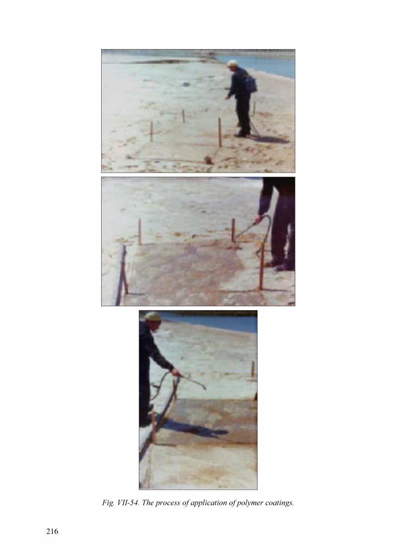
Fig. VII-54. The process of application of polymer coatings.
216

cement in this compound with lime resulted in a drastic reduction of the strength and the
wheathering resistance.
The total quantities of materials needed for coating the beaches with optimum compounds
was estimated and respective figures are given in Table VII-4.
Table VII-18. Estimation of the required quantities of materials to construct covers
Material
Item Surface layer composition
Clay [t] Loam [t] Lime [t] Cement [t] Water [m3
]
1
Clay (45%) + lime (45%) +
cement (10%) + water
555 - 555 123.3 1184
2 Loam + cement (10%) + water - 1009 - 112.1 404
3 Loam + cement (15%) + water - 953 - 168.2 415
The experimental results showed that there is no real alternative to cement based coatings. At
the same time, these coatings are very expensive, and as noted before, no method of
application of such coatings to materials with low mechanical strength is available. Based the
extensive experience in re-cultivation of ponds taken out of service by covering them with a
layer of clay, soil, or loam of 80-100 cm thickness, experiments were undertaken to gradually
cover the beaches with loam. The projected thickness of the layer should have provided
sufficient mechanical strength for filling the whole beach. In fact, about 20% of the beach
surface over most dense part could be covered. However, as soon as it was attempted to cover
the more remote parts of the pond bank, at a distance of 3-4 meters, shear failure of the
underlying tailings occurred with ensuing destruction of the monolith plate. Figure VII-4
illustrates the effect of the shear failure and the resulting beach destruction. Part of the beach
cover has dropped into the tailings and lifted the the top part of the beach, resulting in deep
faults. Thus, it is evident that this method of re-clamation was not feasible.
Generally speaking, the main problem is the low shear strength and load-bearing capacity of
the beach material and, therefore, the emplacement of covers. In consequence, it will be
difficult to solve the problem of the long-term stabilisation of the pond up to complete
dewatering. Therefore, further investigations were focused on the development of coatings
that do not necessarily possess a long service life but that eliminate problem of dust
generation during the time until complete dewaterin is achieved.
In consequence, the making of polymer coatings to prevent dust generation was studied and a
number of field experiments were carrried out. Figure VII-5 shows the process of applying
polymer coatings on part the beach to evaluate their wheathering resistance under natural
conditions.
VII-4. GROUNDWATER CONTAMINATION PROBLEMS
The tailings pond that was taken out of service gives rise to another problem, which is the
contamination of underlying aquifers with radioactive and toxic substances. The bottom liner
of the pond is malfunctioning, allowing the release of contaminants with the ensuing risk of
detriment to the drinking water resources in the Ust-Kamenogorsk area. Figure VII-6 is a map
of groundwater contamination with chlorides and sulfates in the Ust-Kamenogorsk area.
217

Fig. VII-55. Map of chloride and sulfate contamination in the Ust-Kamenogorsk area [VII-3].
Fig. VII-56. Map of As and Be groundwater contamination in the Ust-Kamenogorsk area
[VII-3].
218

Unfortunately, statistical data on the dispersion of radioactive and toxic substances in the
groundwaters are rather limited. However, it is clear that radioactive and toxic contaminants
are migrating together with sulfates, which are a component of the impounded wastes.
Figure VII-7 shows the concentration of beryllium and arsenic in the groundwaters. The
tailings pond appers to be an active source of groundwater contamination.
The Table VII-5 gives some results of groundwater monitoring in the region of the tailings
pond. The Table shows isolated excesses of content of components under control in
subterranean waters in comparison with the drinkable water standard (MAL= maximum
acceptable level) adopted for Kazakhstan [VII-2]. It was registered that the values of specific
alpha and beta activity of subterranean waters and the content of the whole number of harmful
and dangerous substances exceed those fixed in standards.
Table VII-19. Some of groundwater monitoring results
Variable Unit MAL [VII-2] 1 2 3 4
Solid residual mg/l 1000 17390 3370 1230 6900
NO3 mg/l 45 127 487 162 1240
Cl mg/l 350 360
SO4 mg/l 500 10950 1490 510 3270
NH4 mg/l 2 375 2.5 36
As mg/l 0.05 0.06
F mg/l 1.5
Cu mg/l 1
Pb mg/l 0.03 0.17 0.05 0.03 0.11
Zn mg/l 5
Mn mg/l 0.1 0.4
Sr mg/l 7 9.1 7.8
Be mg/l 0.0002 0.0003 0.0004
Li mg/l 0.03 9.4 0.04 3.2
Hg mg/l 0.0005
Zc 556.1 21.5 8.3 172.5
Zc 1-2 321.5 3 2.5 113.5
α Bq/l 0.1 3.9 2.7 0.5 2.6
β Bq/l 1 1.9 1 1
Zc αβ 41 28 5 27
VII-5. DRAINAGE WATER MANAGEMENT SYSTEM
Taking into account the complexity and scale of the problem a project to prevent groundwater
contamination at Ust-Kamenogorsk was developed. This project consists in the building of a
new and state-of-the-art tailing pond for the industrial wastes together with a number of
supporting engineering measures. Figure VII-8 is a conceptual diagram of the tailings pond
and the patterns of contaminanat release to the underlying aquifer.
219

Fig. VII-57. Mechanism of groundwater contamination.
Fig. VII-58. Trapping of underground water.
The project consists of trapping of the main part of the groundwater upstream of the old pond
and diverting it on the surface into the river Irtysh. The contaminated groundwater will be
collected from wells downstream of the new pond then pumped into it. Contaminated dekant
water from the old tailings pond will also be pumped to the new pond. After dewatering of
this old pond it will be possible cover it by one of the known methods for building cappings.
220

VII-6. SUMMARY AND CONCLUSIONS
Thus, the following plan of action for taking the pond out of service service and for providing
for its long-term stability was proposed:
(1) Mathematical simulation of groundwaters flows and the migration of radioactive and
toxic substances;
(2) Construction of a new tailings storage pond, using state-of-the-art methods for liner
construction;
(3) Determination of the optimum arrangement of wells for trapping clean and
contaminated groundwaters based on mathematical simulation;
(4) Drilling of wells for trapping contaminated waters and transfer to the new pond;
(5) Transfer of the dekant water from the old pond to the new storage pond;
(6) Construction of a cover providing for the long-term stability of the old pond.
An important condition of the project success as a whole, is the realisation of a programme for
process improvement to substancially reduce the amount of liquid waste generated. The main
aspects of this program are the introduction of new technologies generating less waste,
improvement of the water circulation pattern in the facility, cooperation with the other
enterprises of the region on recycling and re-use of wastes, and the development of methods
to reduce the amount of harmful components in the wastes.
REFERENCES TO ANNEX VII
[VII-1] VOLZHENSKY, A., BUROV, U., KOLOKOLNIKOV, V. Mineral connecting
substances (Technology and Proporties), Stopoyidat, Moscow (1966). (in
Russian)
[VII-2] GOST 2874-82, “Standards for drinking water quality”, Moscow (1982).
[VII-3] BUNDESANSTALT FÜR GEOWISSENSCHAFTEN UND ROHSTOFFE,
Proposals for the remediation of contaminated groundwater and hazardous
industrial waste sites in the Ust-Kamenogorsk area, Kazakhstan, Technical
Cooperation Project No. 99.0795.7, BGR, Hannover (2001).
221

ANNEX VIII. REPUBLIC OF KOREA
REMEDIATION OF URANIUM MILL TAILINGS USING NATURAL AND
ORGANO-CLAYS
Sang June Choi, Young Hun Kim
Department of Environmental Engineering KyungPook National University,
Taegu, Republic of Korea
Several experimental studies have been conducted for the remediation of uranium mill tailings
using natural and organo-clays. A few sorbents were also tested for the non-uranium
radioactive species such as cobalt and caesium. Natural clays showed pH dependent sorption
characteristics for uranium, indicating the clay surface and uranium species changed with pH
variations. The organo-clays showed reduced sorption capacity for uranium. This result
indicates that uranium species and organic parts of the organo-clays are competing on the the
sorption sites. Therefore, for tailings containing only uranium should be isolated with just
natural clays. However, sites contaminated with radioactive materials and toxic organic
contaminants would be better treated with organoclays. In the last study period, sorption
studies for cobalt were conducted with a few organic sorbents such as Undaria Pinnatifida (a
sea weed). Undaria Pinnatifida showed very high sorption capacity for cobalt. Other sea
weeds are under investigation and other radioactive species such as caesium will be tested.
In recent decades, the use of natural and modified sorbents has been considered for the
remediation of mining and mill tailing sites. Natural clays (e.g. smectites, bentonites,
alumino-silicates, montmorillonites) and clays (e.g. montmorillonite) modified with e.g. the
cationic surfactant hexadecyltrimethylammonium (HDTMA) have been used to reduce the
mobility of heavy metals and radionuclides. Stabilization of uranium mill tailing using natural
and modified clays may prevent migration of residual uranium and reduce the biosorption and
‘bioavailability’ of uranium for uptake by plants, earthworms and microorganisms. In this
research, the potential of natural and organo-clays for immobilizing contaminants in uranium
mill tailings was investigated. The sorption and desorption characteristics are assumed to be
the main controlling factors determining the applicability of these sorbents in the
immobilization of such residues and for the in situ remediation of contaminated sites.
The projects focused on the characterization of the sorption of uranium species on natural and
organically modified clays (organo-clays). Experiments were conducted to investigate
sorption characteristics of selected sorbents. The sorption data generated were used to
calibrate various sorption models. Laboratory studies were conducted to determine the
immobilization capacity of selected sorbents for the treatment of uranium mill tailings
Organic contaminant sorption on an organo-clay has been of significant research interest and
as a new technology attracted many soil and environmental scientists and engineers over the
last decade. Many studies have been reported with organo-clay, suggesting several potential
applications, such as solidification and stabilization of waste effluents, secondary containment
for gasoline storage tanks and hazardous waste landfills liners [VIII-1-VIII-5]. Organoclays,
which are clays modified by insertion of an organic cation into the interlayer or ion exchange
223
VIII-2. INTRODUCTION
VIII-1. ABSTRACT

with inorganic cations, such as Ca2+
, Na+
, and K+
, in the interlayer spacing. The organic phase
provides high sorption capacity for organic contaminants, which partition to this phase.
Two different organo-clays were prepared: montmorillonite modified by exchanging 50% and
100% of the CEC with HDTMA. To test the sorption characteristics, pH was varied as the
most important environmental factor. The studies of competitive sorption and desorption of
uranium and organic contaminants are still ongoing. The effect of humic material will also be
studied. The applicability and economic feasibility of using such clays for in situ treatment of
the uranium mill tailings will be analysed based on the experimental results and numerical
modelling.
A few biosorbent were also tested for low level radioactive liquid waste which produced from
nuclear power plant.
VIII-3.1. Materials and Experimental Methods
Montmorillonite-KSF™ (Aldrich Chemical Co.) was washed with distilled water at 60 ºC for
removal of organic impurities and the removal was monitored by UV of the drained water.
The clay suspension was finally filtered through a 0.22 µm membrane filter, and the filtrate
was checked for impurities by UV-spectrophotometry (Hewlett Packard, 8452A). The
modified montmorillonite was collected by settling, dried for 24 hours, and stored in a brown
clay. 50% and 100% of the CEC was exchanged with the cation used as an organic modifier,
hexadimethylammonium (HDTMA). The details of the procedures can be found in [VIII-7].
The average particle diameter of the collected montmorillonite was about 15 µm.
The HDTMA was obtained as 25 wt% aqueous chloride solution from Aldrich Chemical Co.
and used as received. Natural uranium was purchased from Sigma Chemical Co. as uranyl
nitrate (UO2(NO3)2) and used without further purification. ICP standards were prepared in
acid (HNO3 or HCl) to give a 1000 mg/l U(VI) stock solutions.
Sorption experiments were performed in batches using 40 ml amber vials. Water to clay ratio
was 10:1 w/w%, and the mixtures was open to a CO2(g)- atmosphere during sample
preparation and sealed with Teflon lined caps. The solution pH was controlled with pH
buffers and monitored during at the beginning and at the end of the experiments. After 24
hours of sorption, the solid phase was separated by centrifugation and aliquots were taken
from the aqueous phase for the determination of uranium concentrations in filtered and
unfiltered samples. The aqueous solution was vacuum-filtered through 0.45 µm PTFE filters
and the uranium concentrations were measured by Inductively Coupled Plasma Atomic
Emission (ICP-AE). The sorbed amount of uranium was calculated from the initial and final
uranium solution concentrations.
The data could be best represented with a nonlinear Freundlich sorption isotherm:
N
F
CKq =
(1)
where q (µg·g-1
) = the amount sorbed, and KF (µg·g-1
)/( µg·cm3
) and N (dimensionless) =
Freundlich parameter. N reflects the curvature in the isotherm and may represent the energy
distribution of adsorption sites.
224
VIII-3. SORPTION STUDY WITH NATURAL AND ORGANO-CLAYS
bottle. The cation exchange capacity (CEC) for this clay was determined to be 50.4 meq/100 g

VIII-3.2. Result and discussion
A set of experiments was conducted without any pH buffer. The pH of the solution varied
between pH 3-4 over the experimental period. The non-modified clay exhibits a higher
sorption capacity for uranium than that of organoclay (Figure VIII-1). The solid lines on the
figure represent the Freundlich model fitting and a good fit is observed. The organoclay
modified with 50% or 100% HDTMA showed a decrease of about 50% in the sorbed amount.
This result can be explained thus that the sorption sites for mainly cationic uranium species on
the clay are negatively charged and that some of the negatively charged sites were occupied
by the organic cation. Thus sorption capacity for uranium is decreased as the clay is modified
with organic cations. However, some sorption sites including edge sites that would be
available for uranium.
Figure VIII-2 to VIII-4 show sorption isotherms of uranium for different pH values (pH 6-
10). Figure VIII-2 shows the sorption isotherm of uranium on non-modified clay. At pH 6, the
sorption capacity was the largest and the sorption amount decreased as the pH increases. This
phenomenon was repeated for the 50% HDTMA and 100% HDTMA-modified clays and can
be explained by the speciation of uranium(VI): it exists at pH of 2-4 mainly as UO2
2+
ion,
regardless of the presence of carbon dioxide. UO2
2+
is converted to UO2(OH)+
around pH 5-7,
At even higher pH-values the dominant species will become UO2(OH)2
0
(aq) and UO2(OH)3
-
.
Table VIII-1. Freundlich model parameters for sorption of uranium onto
unmodified clay and HDTMA-clays.
SorptionClay
pH KF n R
2
6 9.7028 0.2535 0.9866
8 1.6879 0.2695 0.9887 Montmorillonite
10 0.0208 0.9619 0.9893
6 9.3107 0.1534 0.8809
8 1.8381 0.2347 0.9945
50% HDTMA
Montmorillonite
10 0.0601 0.7367 0.9854
6 1.2078 0.3543 0.9817
8 2.2306 0.2098 0.9983
100% HDTMA
Montmorillonite
10 0.3816 0.4311 0.9705
Therefore, the cationic U species at low pH have higher sorption affinity for the clay and at
high pH uranium is changed into to neutral or anionic species. This leads to low sorption
affinities for unmodified and organo-clay. The same lower overall sorption capacity of the
organically modified clay can be observed in Figures VIII-2 to VIII-4, as was observed in
Figure VIII-1 with unbuffered solutions. Figure VIII-2 to VIII-4 indicate that the pH effect is
higher for the unmodified clay, while the effect is diminished as the ratio of HDTMA
exchange increases. For the unmodified clay a significant difference was observed between
pH 6 and pH 8 (Fig. VIII-2), while this difference is much smaller for the modified clays
225

(Figs. VIII-3 and VIII-4). A summary of the fitted Freundlich model parameters is given in
Table VIII-1.
Fig. VIII-1. Sorption isotherm of uranium without pH buffer. Lines represent Freundlich
isotherms.r.
Fig. VIII-2. Sorption of uranium on montmorillonite at pH 6-10. Lines represent Freundlich
isotherms.
226

Fig. VIII-3. Sorption of uranium on 50% HDTMA-montmorillonite at pH 6-10. Lines
represent Freundlich isotherms.
Fig. VIII-4. Sorption of uranium on 100% HDTMA-montmorillonite at pH 6-10. Lines
represent Freundlich isotherms.
227
The results indicate that the sorption mechanism are not same for all of the tested clays. On
the unmodified clay, cations, such as Na +
, Ca2+
, or K+
, can be exchanged for uranium, but on
the organoclay, the organic cation will not readily exchange with the uranium cations. The
Freundlich model is not intended for evaluating competitive sorption effects.
To analyse multicomponent competitive adsorption behaviors, inter alia the Langmuir
Competitive Model (LCM) [VIII-8], the Ideal Adsorption Solution Theory (IAST) model
could be used [VIII-8]. LCM is an extended form of the Langmuir model that allows
predictions of the amount of solute i adsorbed per unit weight of adsorbent, qm,i , in the
presence of other solutes.
∑=
+=
n
j
jej
jejim
ie
Cb
Cbq
q
1
,
,,
,
1
(2)
where Ce is the equilibrium concentration of solute i in a mixture consisting of n components,
while Ce,j are the equilibrium concentrations of all the adsorbing solutes in the mixture. The
constants bi, bj and qm,i, qmj are determined from single-solute systems.
Biosorbents are well known as high sorption capacity for heavy metals. They could apply for
radionuclides including uranium. In this study a few biosorbents were tested for fission
products such as Co, Sr, Cs. Biosorbents might use with organoclay to increase the sorption
capacity multicontamination.
VIII-5.1. Materials and methods
Three sorbents, Chlorella, Spirulina, and Undaria Pinnatifida were studied for the cobalt
removal from liquid waste. The liquid waste was prepared from non-radioactive compounds
to avoid exposure to the laboratory workers. NaNO3, KNO3, Ca(NO3)2, Co(NO3)2, CsNO3
were purchased from Aldrich Chemicals. All the chemicals were used as received from the
vender without further purification. Co(II) stock solution was prepared by dissolving
Co(NO3)2 into nano-pure water. The sorbents was pH adjusted and the cobalt stock solution
was added. All the kinetic and isothermal tests were conducted in a temperature controlled
shaker (VS-8480SF, Hanil) at 200rpm and 25ºC. 0.1 N of HCl was used for the pH
adjustment. The solid to liquid ratio was 150 (0.2 g sorbents and 30 ml nano-pure water). The
sample solution was filtered with 0.22 µm syringe filter or centrifuge for 10 minutes at 1700
rpm (Hanil, MF600). The prepared solution was ananlyzed with AAS (atomic adsorbed
spectrometer, Varian Spectra AA 250 Plus). The qe was calculated with a following equation.
qe = (C0-Ct)V/M (3)
where C0: initial concentration, Ct: concentration after equilibrium, V: volume of liquid, and
M: weight of the sorbent. The sorption isotherm was fitted with the Freundlich model.
VIII-5.2. Results and discussion
Chlorella and spirulina have showed low sorption capacity for Co and Cs in preliminary
experiments. Hence, these two sorbents were not subject to more detailed studies.
228
VIII-4. Evaluation of competitive binding effects
VIII-5. Experiments with biosorbents

VIII-5.2.1. Kinetic study for Undaria pinnatifida
Figure VIII-5 shows the result of kinetic studies with Co. Equilibrium was achieved within 30
minutes. The quick attainment of equilibrium is essential for a compact design of a reactor.
Good cadidates of sorbent should have fast kinetic properties. However, all the sorption
isotherm experiment were given 2 hours to ensure the equilibrium.
Fig. VIII-5. Sorption kinetic of Co on Undaria pinnatifida.
VIII-5.2.2. Sorption isotherm for Undaria pinnatifida
Figure VIII-2 shows the sorption isotherm for Co on Undaria pinnatifida at differnt pH-
values. The results indicate that the sorption capacity of Undaria pinnatifida is rather high in
comparison to other sorbents. Table VIII-I. shows the sorption capacity for three different
sorbents. Figure VIII-2 also indicates that the sorption characteristics are independent of the
solution pH. There is no significant difference for pH 4 and pH 7. This indicates that the
sorption mechanism is not dependent on the proton concentration. Complexation between the
metal and functional groups on the organic materials, such as –OH and –COOH was proposed
in the literature as a fixation mechanism. However, the present results seem to indicate that
the major fixation mechanism on Undaria pinnatifida is not complexation, but ion exchange.
Table VIII-1. Sorption amount (mg/g) in single solute system of Undaria pinnatifida for Co
(C0= 200 mg/l)
Sorbent Chlorella sp. Spirulina sp. Undaria Pinnatifida
Co 3.2 7.5 25
Cs 2.4 1 under investigation
229

(a) pH 4, (b) pH 7.
Fig. VIII-6. Sorption isotherm of Co on Undaria pinnatifida for different pH values.
VIII-5.2.3. Effect of non-radioactive salts
Other metal constituents, such as sodium, calcium, magnesium, iron, in solutions to be treated
compete for binding places on the substrate [VIII-6]. Figure VIII-7 shows the effect of sodium
on the sorption of cobalt on Undaria pinnatifida. The effect of sodium in not significant.
Usually the multivalent ion have higher competition effect. Currently the effect of calcium
and magnesium on the cobalt sorption is under investigation.
Fig. VIII-7. The effect of Na on the binding of Co on Undaria pinnatifida.
VIII-5.2.4. Biosorption for other radioactive species with seaweeds
The current result of biosorption showed that the sea biomaterial have a high sorption
capacity and suggested further studies with the material targeting other radioactive materials
such as Cs, Sr, and U. We keep working on the experimental study for removal of
radioactives with biomaterials.
230

At first sorption study of uranium on natural clay and organo- clay. Generally, lower pH
showed higher sorption amount and the sorption was decreased as the solution pH increased.
It can be explain as UO2
2+
is the dominant species for the lower pH while UO2(OH)+
,
UO2(OH)2
0
(aq), UO2(OH)3
-
have low sorption characteristics to the clay and organo-clay.
Organo-clay showed lower sorption capacity for uranium sorption in comparing with non-
modified clay. This results imply the some sorption sites for uranium species are competing
with HDTMA but not all of the sites are occupied by HDTMA indicating the organo-clay can
be used for sites which contaminated with toxic organic compounds and uranium.
At second experimental study, biosorption for low level radioactive liquid waste.
Among the tested three biosorbents, Undaria pinnatifida has the highest sorption capacity for
cobalt and implicate that biosorbents could be a good cadidate for concentrating and/or
removal of ionic radioactive materials.
REFERENCES TO ANNEX VIII
[VIII-1] LO, I.M.-C., Solidification/stabilization of phenolic waste using organic-clay
complex, J. Environ. Eng., 122 9 (1996) 850–855.
[VIII-2] LO, I.M. C., YANG, X. Y., Use of organoclay as secondary containment for
gasoline storage tanks, J. Env. Eng., 127 2 (2001) 154–161.
[VIII-3] BOYD, S.A., MORTLAND, M.M., CHIOU. C.T., Sorption characteristics of
organic compounds on hexadecyltrimethylammonium-smectite, Soil Sci. Soc. Am.
J., 52 3 (1988) 652–657.
[VIII-4] SMITH, J.A., JAFFE, P.R., Benzene transport through landfill liners containing
organiophilic bentonite, J. Env. Eng., 120 6 (1994) 1557-1559.
[VIII-5] LI, J., SMITH, J.A., WINQUIST, A.S., Permeability of earthen liners containing
organobetonite to water and two organic liquids, Environ. Sci. Technol., 30 10
(1996) 3089-3093.
[VIII-6] QIMING, YU, JOSE, T.M., PINGHE, Y., PAIRAT, K., Heavy metal uptake
capacities of common marine macro algal biomass, Wat. Res., 33 6 (1999) 1534–
1537.
[VIII-7] KIM, Y.S., SONG, D.I., JEON, Y.W., CHOI, S.J., Adsorption of organic phenols
onto hexadecyltrimethylammonium-treated montmorillonite, Sep. Sci. Technol.,
31 20 (1996) 2815–2830.
[VIII-8] YEN, C.Y., SINGER, P.C., Competitive adsorption of phenols on activated
carbon, J. Environ. Eng., 110 5 (1984) 976–989.
[VIII-9] RADKE, C.J., PARUSNITZ, J.M., Thermodynamics of multi-solute adsorption
from dilute liquid solutions, Aiche, 18 4 (1972) 761–768.
231
VIII-6. Summary and Conclusion

ANNEX IX. POLAND I
IMPROVEMENT OF SOIL PROPERTIES APPLIED TO CAPPING AND MULTI-
LAYER BARRIERS
J. Koszela
Institute of Geotechnics and Hydrotechnics, Wroclaw University of Technology, Poland
IX-1. ABSTRACT
Results are presented on the research on the selection of natural clayey materials for the
remediation of mill tailings and the possible control of their properties. The following
objectives were formulated: a) minimizing of the required soil mass, b) improvement of the
material employed. Three methods for the modification of clayey soil were examined:
application of an external electrical field,
hydrolysis by applying strong acids and strong bases,
a combinded method.
The research focused on two types of clays, on a kaolinite and on a illite/smectite. An electric
field of E= 0.2 V/cm was used. The samples were also treated with 0.1 N chloric acid, strong
base, peptizing agent and an industrial waste solution from an etching processes. Remaining
heavy metal concentrations in the solutions were used as a measure for the effectiveness of
modification to the clays.
Both, the chemical and the electrical method generated similar changes in the clay structures.
The electrical method appeared to be simpler in field applications. However, the research
showed that the chemical treatment of the clay material was the most efficient. Disappointing
results where obtained from the electrical treatment of samples, i.e. the sorptive properties of
clays did not improve substantially and the pH change was ambigeous.
IX-2. INTRODUCTION
The process of mining and milling of uranium ore results in tailings that are deposited in
ponds. The tailings consist of ground-up minerals and of process water. From a geotechnical
point of view these tailings have a liquid or semi-liquid consistency. The tailings pore waters
may be acid, neutral, or alkaline, depending on the process technology. The pore water may
also contain various radionuclides and heavy metals, as well as contaminants such as oils.
The properties of the tailings itself, as well as tailing ponds construction pose a significant
threat to the environment. Remediation of tailing ponds and the surrounding environment can
be very complex process [IX-1–IX-3]. The effectiveness of the technical solutions applied is a
function of quantity and quality of data, as well as of suitable models [IX-1,IX-3].
The most significant technical problems are old, abandoned tailing ponds. Typically a
combination of three independent barriers is present: geological barriers, technical barriers
and waste body itself as barrier. Technical barriers include capping in order to limit water
ingress and contaminants migration, radon release, as well as direct radiation exposure [IX-1,
XI-3]. Simon and Müller [XI-3] divided the capping systems to: Standard capping systems
and alternative capping systems. In the standard capping system there are used natural and
233

conventional synthetic materials (e.g. clays, geomembranes) for their conventional properties
(flexibility, impermeability, etc.). It sometimes happens that economical and technical
conditions call for unconventional solutions, that is alternative capping system [IX- 3].
The goal of the present work is finding new alternative solutions for the capping and isolation
of tailing ponds. Generally, such alternative solutions consists of physical or chemical
modifications to conventional materials, allready built into the capping layers (activation or
modification of properties) or applying a new, modified conventional material. The
effectiveness of the new layers consists in active reaction with the tailing pond environment
for example adsorption and immobilization of heavy metals.
As was shown by earlier research [IX-4–IX-6], as well as by research of others [IX-7–IX-12]
that alternate application of strong acid and base to clayey soils causes hydrolyses of clayey
minerals. Such modified clayey soils show improved sorbing properties for radionuclides and
heavy metals. When added to the tailings, such modified clays, would counteract the
migration of radionuclides and heavy metals. In the research presented here previously
developed methods [IX-4,IX-6,IX-13,IX-14] were adapted and earlier results were put into
perspective [IX-5,IX-6,IXI-14].
IX-3. THE SCOPE AND OBJECTIVES OF THE RESEARCH
The following goals and objectives have been used to conceptualise the research work:
Research goals
Improvement of the retention capacities of clay layers;
Elimination or decrease of migration of contamination from tailing pond;
Immobilization of heavy metals/radionuclides and trapping them in the tailing pond.
Research Objectives
Modification of clays that are conventionally used in tailing ponds to construct barriers;
The agents and materials should be easily obtainable (preerably of local origin);
The technology should not be complicated.
Earlier work [IX-4, IX-6,IX-8,IX-10,IX-17] has shown that the sorptive capacity of clays can
be increased by modifying the structure through treatment with strong acids and bases. The
modification of the structure facilitates the penetration of ions and the chemical treatment
weakens the aluminosilicate bonds Si – O – Al.
Building on previous studies of electro-osmotic effects [XI-13,XI-14], it was found that
electro-osmosis is capable of modifying the structure of clays [IX-4,IX-7,IX-15,IX-16,IX-18,,
XI-19]. This forms the fundamental idea of the present research work, by which it was
observed that an external electric field changes the properties of clays in a way similar to the
treatment with acid and bases.
Emphasis was placed on:
a) improvement of the retention capacities of the clays by modification of their properties
b) creating new alternative layers on the basis of clay minerals
234

The property modifications to the clay minerals are brought about by applying an electric
current (electrokinetic processes) or applying of strong acids and basics (clay mineral
hydrolysis).
IX-4. EXPERIMENTS WITH AN EXTERNAL ELECTRIC FIELD
IX-4.1.Materials investigated
Kaolinite from the ‘Maria’ mine in Nowogrodziec and illite/smectite clay from the ‘Kraniec’
mine near Brzeg Dolny were used in the studies. Four samples of paste consistency (ca. 50%
water content) were prepared form these materials. One samples served as a control and was
untreated, while a second and third were subject to electro-osmosis, and the fourth was treated
with the 0.1 N HCI for a time-period of one day. Sub-samples of these preparations were
dried and subjected to microscopic examination in the air-dry state.
IX-4.2.Characteristics of external electric field
The experiments with an external electric field were carried out in rectangular plastic
containers. The clay samples had a dimension of 15 × 15 × 50 cm.
The electrodes (three anodes and cathodes each) were made from 10 mm diameter perforated
stainless steel tubes. The spacing between the anodes and the cathodes was L = 40 cm. A
direct current (DC) of E = 0.2 V/cm electric field intensity was applied. The polarity was
changed at 8 hour intervals in a second set of experiments.
IX-4.3.Microscopic examination
An STEREOSCAN-180 electron-microscope was used for the inspection of the gold-coated
samples at the magnifications of 1000, 3000 and 10000 times. Black and white image of the
structures were taken (see Figs. IX-1 to IX-6).
IX-4.4.Experimental results
The electron microscope examinations show that the clays in their natural, unaltered state
consist predominantly of microaggregates with ‘surface to surface’ type contacts, and there
are more ‘interparticle’ pores than ‘interaggregate’ ones. The unaltered clays are characterised
by a laminar/domain-like structures (Figs. IX-1 and IX-2).
Treatment with 0.1 N hydrochloric acid (HCI) changes the morphology of the clay minerals
as shown in in the electron microscope images (Figs. XI-3 and IX-4). The most important
changes observed include:
formation of aureoles of tiny matter around particles and aggregates, resulting in an
obliteration of the sharpness of the primary shapes;
exposure of tiny, single silt grains;
formation of interaggregate pores of 0.003-0.005 mm average diameter;
increase in the number of ‘mixed’ type contacts as opposed to ‘surface to surface’ type
contacts;
formation of a matrix/turbulent structure [IX-16].
235

Fig. IX-1. Kaolinite. The structural construction (fabric) before the action of electric current
and HCl.
Fig. IX-2. Illite/smectite clay from the ‘Kraniec’ mine.
236

Fig. IX-3. Kaolinite after the activation with 0.1 N HCI.
Fig. IX-4. Illite/smectite clay after the activation with 0.1 N HCI.
237

Fig. IX-5. Kaolinite after electro-osmosis – anodic zone.
Fig. IX-6. Illite/smectite clay after electro-osmosis – anodic zone.
238

These changes are more evident in the illite/smectite (Fig. IX-4) than in the kaolinite samples
(Fig. IX-3).
The application of external electric fields (electro-osmosis) with a constant polarity DC
generates in the perianodic zone structural changes similar to those produced by the acid
treatment. The changes having a similar character for both clay types examined (Figs. IX-5
and IX-6), namely:
specific aureoles are formed on mineral aggregates and on single particles;
the domain-type of the structural pattern are preserved, with an evident transformation
in the matrix structure [IX-16];
Numerous interaggregate pores of 0.001-0.003 mm diameter are formed.
The experiments during which the polarity the of electrodes was changed every eight hours
did not induce an effect significantly different from that with constant polarity. The
illite/smectite clay showed features almost identical to those produced with a constant
polarity, while the kaolinite structure did not differ from the initial structure very much.
IX-5. CHEMICAL MODIFICATION OF CLAY SORPTION PROPERTIES
IX-5.1.Clays
The illite/smectite clays from the ‘Kraniec’ mine near Brzeg Dolny (Poland), used in these
experiments, were in the dry-air state, while samples for the electro-osmosis experiments
were made up from material at the natural water contents (21.5%).
IX-5.2. Industrial waste solutions
The metal removal capacity of the clays was investigated by bringing samples into contact
with simulated tailings porewaters. As a subsitute an industrial waste solution from a metal
pickling process at one of the metallurgical plants in Wrocław was used. The experiments had
to give answers to the following:
would consituents of the industrial waste solution be sorbed by the clays and to what
extent ?
what are the reagents proportions needed to achieve the highest effectiveness of the
clays as alternative layers to prevent heavy metal migration ?
The respective metal concentrations in the industrial waste solution are given in Table IX-1.
Table IX-1. Heavy metals contents and pH in industrial wastes.
Measured concentration Allowable max. value as per Polish standard
Zinc 158 mg/dm3
2.0 mg/dm3
Copper 72 mg/dm3
0.5 mg/dm3
Lead 1.95 mg/dm3
0.5 mg/dm3
Chromium < 0.1mg/dm3
0.2 mg/dm3
pHreaction 2.75 6.5-9.0
239

IX-5.3.Clay modification method
The air-dry clay was activated in an acidic dispersion using 0.1N HCl of pH2-2.5, then in a
CaOH solution of 12-14 pH. Adding 1% of 15M NaOH or sodium water-glass acted as
peptising agent. The procedures were adapted from earlier experiments [IX-5,XI-6].
The treatment was carried out in a blender, adding first the acid, then the base, and finally the
peptising agent. The added chemicals resulted in a paste-like consistency of the clays.
Untreated, in a natural state, clay was used for the electro-osmotic experiments. A DC of E =
0.2 V/cm field intensity was passed through the clays over a period four days The
experiments were carried out in a 15×15×50 cm plastic container. The electrodes were made
from brass pipes (Ø 10mm) wrapped with a brass net. They were arranged vertically so there
were three cathodes at one end and three anodes at the other. The anodes respectively
cathodes were spaced 3 cm apart and the distance between cathodes and anodes was 40 cm.
Samples were taken from the peri-anodic and peri-cathodic zones.
Three series of tests were carried out:
Series I: waste solution + modified clay
Series II: waste solution + modified clay + water-glass
Series III: waste solution + clay after electro-osmosis
IX-5.4.Criteria for the effectiveness of the treatment
Two criteria were applied to evaluate the treatment effectiveness [IX-4–XI-6]:
(1) The final pH(f) achieved in the waste solution compared to the discharge requirements
in the range of pH 6.5 to 8.5.
(2) The reduction of the contaminant concentrations in the effluents with respect to the
maximum allowable value as per Polish discharge standard.
IX-5.5.Experimental results obtained
Series I: waste solution + clay
In this series various ratios of waste solution to clay were tested and the effect was expressed
in terms of the final pH(f) reaction.
Test I/1 waste solution / clay = 1000 / 1
Test I/2 waste solution / clay = 500 / 1
Test I/3 waste solution / clay = 333 / 1
Test I/4 waste solution / clay = 250 / 1
240
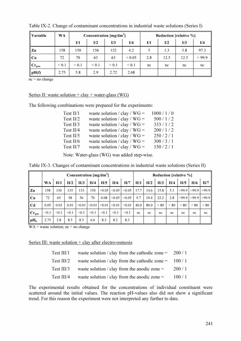
Table IX-2. Change of contaminant concentrations in industrial waste solutions (Series I)
Variable WA Concentration [mg/dm3
] Reduction [relative %]
I/1 I/2 I/3 I/4 I/1 I/2 I/3 I/4
Zn 158 150 156 152 4.2 5 1.3 3.8 97.3
Cu 72 70 63 63 < 0.05 2.8 12.5 12.5 > 99.9
Crgen.
< 0.1 < 0.1 < 0.1 < 0.1 < 0.1 nc nc nc nc
pH(f) 2.75 5.8 2.9 2.72 2.68
nc = no change
Series II: waste solution + clay + water-glass (WG)
The following combinations were prepared for the experiments:
Test II/1 waste solution / clay / WG = 1000 / 1 / 0
Test II/2 waste solution / clay / WG = 500 / 1 / 2
Test II/3 waste solution / clay / WG = 333 / 1 / 2
Test II/4 waste solution / clay / WG = 200 / 1 / 2
Test II/5 waste solution / clay / WG = 250 / 2 / 1
Test II/6 waste solution / clay / WG = 300 / 3 / 1
Test II/7 waste solution / clay / WG = 150 / 2 / 1
Note: Water-glass (WG) was added step-wise.
Table IX-3. Changes of contaminant concentrations in industrial waste solutions (Series lI)
Concentration [mg/dm3
] Reduction [relative %]
WA II/1 II/2 II/3 II/4 II/5 II/6 II/7 II/1 II/2 II/3 II/4 II/5 II/6 II/7
Zn 158 130 135 133 150 <0.05 <0.05 <0.05 17.7 14.6 15.8 5.1 >99.9 >99.9 >99.9
Cu 72 65 58 56 70 0.08 <0.05 <0.05 9.7 19.4 22.2 2.8 >99.9 >99.9 >99.9
Cd 0.05 0.03 0.01 <0.01 <0.01 <0.01 <0.01 <0.01 40.0 80.0 > 80 > 80 > 80 > 80 > 80
Crgen
<0.1 <0.1 <0.1 <0.1 <0.1 <0.1 <0.1 <0.1 nc nc nc nc nc nc nc
pHk
2.75 2.8 8.5 8.5 6.6 8.3 8.2 8.3
WA = waste solution; nc = no change
Series III: waste solution + clay after electro-osmosis
Test III/1 waste solution / clay from the cathodic zone = 200 / 1
Test III/2 waste solution / clay from the cathodic zone = 100 / 1
Test III/3 waste solution / clay from the anodic zone = 200 / 1
Test III/4 waste solution / clay from the anodic zone = 100 / 1
The experimental results obtained for the concentrations of individual constituent were
scattered around the initial values. The reaction pH-values also did not show a significant
trend. For this reason the experiment were not interpreted any further to date.
241

IX-6. SELECTED EXPERIMENTS WITH MODIFIED CLAYS
It was noticed earlier work that an electric current and strong acid and basics cause similar
structural changes. However, it turned out that the electrokinetic method is difficult to apply
in practice. For this reason, work with electrokinetic method was discontinued and the
research programme on modification using chemical methods was enlarged. The results of
two out of several modification experiments with clays are discussed below.
IX-6.1.Experiment A
IX-6.1.1. Petrological properties of the clay used
The material used was an illite-montmorillonite clay of tertiary age, containing 44.2% of clay
particles with a diameter d<0.001 mm, 34.9% in the fraction 0.001 – 0.01 mm, and 20.9% in
the fraction 0.01 – 1mm. The plasticity index is Ip = 34%.
IX-6.1.2. Chemical composition of soil
The chemical composition of the soil was determined as:
SiO2 62.1% Fe2O3 8.13%
Al2O3 18.51% SO3 0.38%
MgO 1.7% CaO 6.32%
K2O 0.3% Na2O 0.50%
Total carbonate >10% Loss on ignition 1.48%
pH 7.8
IX-6.1.3. Preparation and characteristics of the suspension
After careful disintegration, a series of samples were prepared from the clay. The suspensions
were prepared in distilled water, or 0.1 N of HCl or H2SO4. Some suspensions were
neutralized by adding enough lime or cement together with an additional dosage of NaOH to
achieve a pH 12 – 14 (see Tabs. IX-4 and IX-5). Finally the peptizing agent was gradually
added. Some of the suspensions were prepared at room temperature and pressure, while others
were heated to 100ºC. The full set of suspensions prepared is listed in Table IX-4.
In order to measure their removal capacities, the suspensions then were mixed and stirred for
one minute with a solution containing heavy metals (% by weight):
Ni – 0.123; Zn – 0.203; Se – 0.14; Pb – 0.010; Cd – 0.059, with a solution pH = 6.0.
The heavy metals removal from the solution was calculated in percent relative to the initial
value and is presented in the Table IX-5. The results obtained indicate that the assumed
modification of clay is adequate for release, and its effectiveness depends only on the used
reagents and proportions.
242

Table IX-4. Characteristics of the various suspensions prepared for experiment A.
Suspension in water:
I 8 parts by weight of clay and 100 parts by weight of water.
Peptized clayey suspension in water:
II 8 parts by weight of clay, 0.05 parts by weight of tannin as a peptizing agent, 100 parts by weight of
distilled water
Peptized clayey suspension in water:
III 8 parts by weight of clay, 0.1 parts by weight of clay of 15M NaOH as peptizing agent, 100 parts by
weight of distilled water.
Peptized clayey suspension in water:
IV 8 parts by weight of clay, 0.05 parts by weight of 1 N sodium pyrophosphate (Na4P2O
7), 100 parts
by weight of distilled water.
Clayey suspension in HCl solution (pH = 2):
V 8 parts by weight of clay, 100 parts by weight of 1 n HCl.
Clayey suspension in HCl solution (pH = 2):
VI 8 parts by weight of clay, 100 parts by weight of 1 n HCl, followed by a neutralization with calcium
5 parts by weight of CaO, i.e. to obtain pH = 12 and introduction of 0.1 parts by weight of tannin
(peptizing agent) with heating to 100ºC.
Calciferous-clayey suspension in water:
VII 8 parts by weight of clay, 5 parts by weight of CaO, 100 parts by weight of distilled water.
Cement-clayey suspension in water:
VIII 8 parts by weight of clay, 5 parts by weight of cement, 100 parts by weight of distilled water.
Clayey suspension in a solution of H2SO
4 (pH = 2):
IX 8 parts by weight of clay, 100 parts by weight of 1 n H2SO
4, followed by neutralization utilizing
additives: 8 parts by weight of cement, 0.15 parts by weight of tannin, and heating to 100ºC.
Table IX-5. Percentage of heavy metal removal for experiments A [relative to the initial
value].
Suspension Ni Zn Se Pb Cd
I 26.8 37.5 47.1 45.0 37.3
II 36.3 42.8 48.6 50.7 42.3
III 31.2 39.9 48.2 47.0 41.9
IV 39.1 43.4 49.2 51.4 44.3
V 29.8 39.2 48.1 49.9 43.5
VI 97.6 99.0 78.6 90.0 96.6
VII 84.3 87.1 68.9 83.5 82.4
VIII 76.7 81.2 74.5 77.9 83.1
IX 98.4 99.5 85.7 95.0 98.6
243
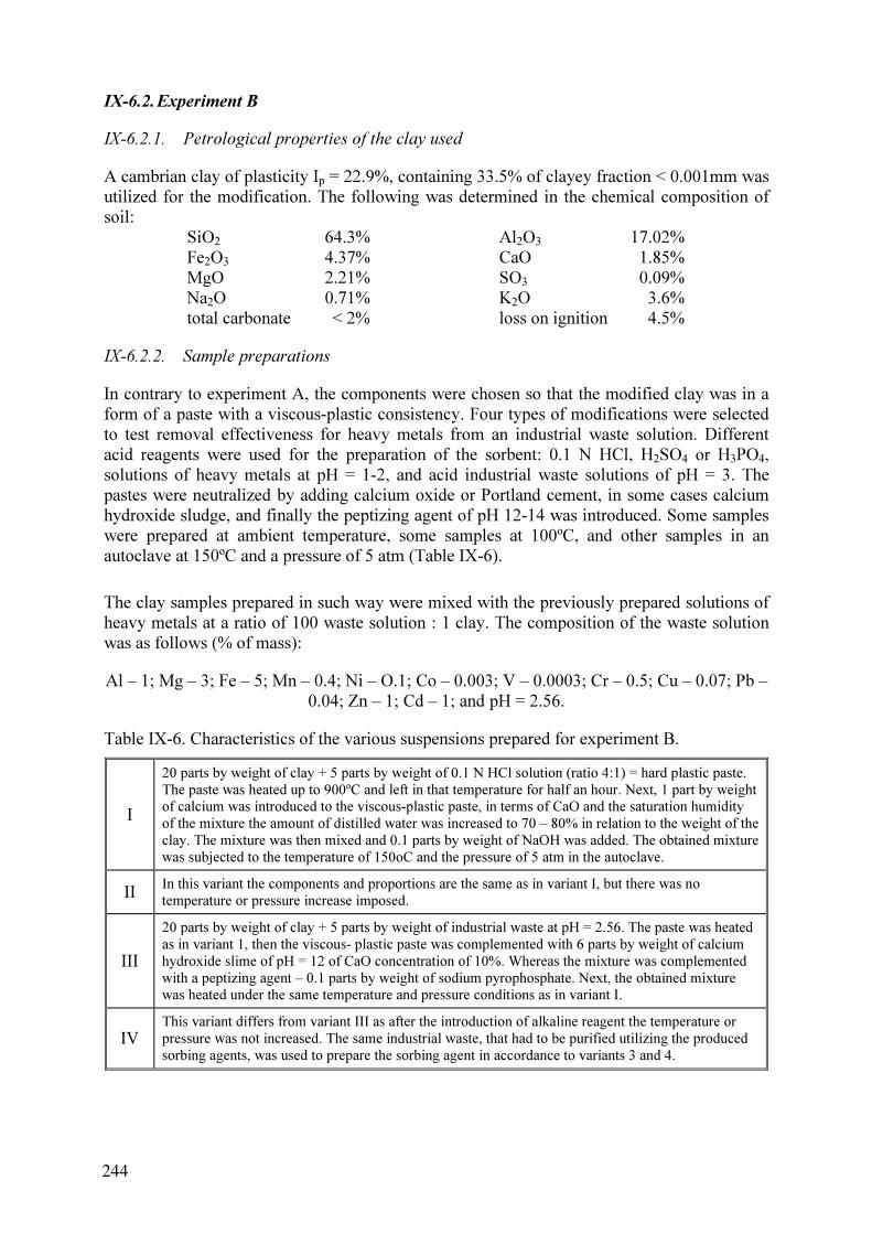
IX-6.2.Experiment B
IX-6.2.1. Petrological properties of the clay used
A cambrian clay of plasticity Ip = 22.9%, containing 33.5% of clayey fraction < 0.001mm was
utilized for the modification. The following was determined in the chemical composition of
soil:
SiO2 64.3% Al2O3 17.02%
Fe2O3 4.37% CaO 1.85%
MgO 2.21% SO3 0.09%
Na2O 0.71% K2O 3.6%
total carbonate < 2% loss on ignition 4.5%
IX-6.2.2. Sample preparations
In contrary to experiment A, the components were chosen so that the modified clay was in a
form of a paste with a viscous-plastic consistency. Four types of modifications were selected
to test removal effectiveness for heavy metals from an industrial waste solution. Different
acid reagents were used for the preparation of the sorbent: 0.1 N HCl, H2SO4 or H3PO4,
solutions of heavy metals at pH = 1-2, and acid industrial waste solutions of pH = 3. The
pastes were neutralized by adding calcium oxide or Portland cement, in some cases calcium
hydroxide sludge, and finally the peptizing agent of pH 12-14 was introduced. Some samples
were prepared at ambient temperature, some samples at 100ºC, and other samples in an
autoclave at 150ºC and a pressure of 5 atm (Table IX-6).
The clay samples prepared in such way were mixed with the previously prepared solutions of
heavy metals at a ratio of 100 waste solution : 1 clay. The composition of the waste solution
was as follows (% of mass):
Al – 1; Mg – 3; Fe – 5; Mn – 0.4; Ni – O.1; Co – 0.003; V – 0.0003; Cr – 0.5; Cu – 0.07; Pb –
0.04; Zn – 1; Cd – 1; and pH = 2.56.
Table IX-6. Characteristics of the various suspensions prepared for experiment B.
I
20 parts by weight of clay + 5 parts by weight of 0.1 N HCl solution (ratio 4:1) = hard plastic paste.
The paste was heated up to 900ºC and left in that temperature for half an hour. Next, 1 part by weight
of calcium was introduced to the viscous-plastic paste, in terms of CaO and the saturation humidity
of the mixture the amount of distilled water was increased to 70 – 80% in relation to the weight of the
clay. The mixture was then mixed and 0.1 parts by weight of NaOH was added. The obtained mixture
was subjected to the temperature of 150oC and the pressure of 5 atm in the autoclave.
II In this variant the components and proportions are the same as in variant I, but there was no
temperature or pressure increase imposed.
III
20 parts by weight of clay + 5 parts by weight of industrial waste at pH = 2.56. The paste was heated
as in variant 1, then the viscous- plastic paste was complemented with 6 parts by weight of calcium
hydroxide slime of pH = 12 of CaO concentration of 10%. Whereas the mixture was complemented
with a peptizing agent – 0.1 parts by weight of sodium pyrophosphate. Next, the obtained mixture
was heated under the same temperature and pressure conditions as in variant I.
IV
This variant differs from variant III as after the introduction of alkaline reagent the temperature or
pressure was not increased. The same industrial waste, that had to be purified utilizing the produced
sorbing agents, was used to prepare the sorbing agent in accordance to variants 3 and 4.
244

After mixing, chemical analyses were carried out and the effectiveness of metal removal was
determined (% relative to the initial concentration). The results are given in Table IX-7 and
show a high removal effectiveness regardless of the preparation. It was also noted that the
consumption of acid and alkaline reagents was several times lower than that for suspensions,
and at the same time, a significant increase of acid and alkaline hydrolysis, followed by
peptization was observed.
Table IX-7. Percentages of metal removal for experiments B [% relative to the initial
concentration].
Susp. Al Fe Mn Ni Cr Cu Pb Zn Cd total
I 97.0 99.4 99.2 99.5 100 99.0 100 100 100 99.2
II 93.4 97.1 92.2 90.1 95.6 94.8 96.9 92.7 95.8 94.3
III 99.5 99.9 99.5 99.5 97.0 100 96.9 100 100 99.5
IV 95.2 97.8 96.3 94.1 96.5 98.2 97.1 93.8 97.6 96.3
IX-7. SUMMARY AND CONCLUSIONS
In this work the effect of inorganic chemicals and electrical field on the sorption properties of
various clays. Activation of these sorption properties is key to creating new, alternative ways
of constructing isolations and capping for tailing ponds or to revitalise old, ineffective clay
layers.
Clays were mixed with 0.1 N hydrochloric acid and left to react for one day to induce
hydrolysis. Hydrolysis occurs more intensively in illite/smectite clays than it does in kaolinite.
A perceptible tendency to break the domain-type structure, the formation of aureoles on the
surfaces of particles and aggregates, the formation of oval interaggregate pores of 0.003-0.005
mm diameter are evident effects of structural transformations.
An external DC electric field, of E = 0.2 V/cm, both with static and periodically changing
polarity induced changes similar to those observed with acid treatment. These changes are,
however, less intensive, manifesting themselves mainly by the formation of aureoles and
interaggregate pores. An appropriately selected electric field could be used to induce a
controlled changes in the clay properties.
The cyclical changes of the polarity induced similar changes as the continuous current flow.
Investigations showed that electric current induces substantial structural changes in the first
flow phase, that is up to eight hours.
The properties of illite/smectite clay were modified with mineral acids and a strong base with
appropriate pH adjustment (NaOH and water-glass).
In preliminary experiments the most effective dosages of modifying agents were selected with
a view to achieve an optimum sorption activity. The clays thus modified were used as a
sorbent for the treatment of industrial waste solutions containing heavy metals. The
effectiveness of metal removal and neutralisation at various ratios of clay to waste solution
was determined.
245

The most effective combination appeared to be the ones in which waste solution was mixed
with modified clay and with an additive of water-glass at the ratios of 250 / 2 / 1; 300 / 3 / 1,
and 150 / 2 / 1. In addition, the expected buffering of pH was obtained for these mixtures with
a considerably lower addition of modified clay.
The modification of clay properties using electric current did not yield results similar to those
by chemical modification. The changes in sorptive capacities, as expressed in terms of the
final heavy metals concentration in the suspensions, were erratic. The final pH values are
difficult to interpret. For this reason, this avenue was not followed further.
The experimental results indicate that modified clays may be a useful component in barriers
that are intended to prevent the migration of radionuclides and heavy metals in seepage from
tailing ponds. Chemically modified clay may also be added to the tailings themselves in order
to increase their retention capacity for radionuclides and heavy metals.
ACKNOWLEDGEMENTS
Testing the modification of properties of clayey soils in laboratory conditions was conducted
by J. Koszela (Wroclaw University of Technology), J. Kryza (University of Wroclaw), as well
as W.M. Knatko and E.W. Shcherbakova E. (University of St. Petersburg, Russia). Testing
the electrokinetical modification and clay structures was conducted by J. Koszela.
REFERENCES TO ANNEX IX
[IX-1] BAUMGARTL, T., HORN, R., RICHARDS, B.G., JUNGE, T., “Possibilities for
long-term security of capping systems of landfills using mineral substrates”, in:
JAKUBICK, A.T., MAGER, D., METZLER, D.R. (Eds.), UMREG 2002, Uranium
Mine Remediation Exchange Group, Workshop Proceedings, Chemnitz (2003)
179–189.
[IX-2] MELCHIOR, S., STEINERT, B., FLÖTER, O., “A comparison of traditional clay
barriers and the polymer-modified material trisoplast in landfill covers”, COSSU,
R., CHRISTENSEN, H., STEGMANN, R., (Eds.), Proc. 8th Intern. Waste
Management and Landfill Symp., Cagliari, Sardinia, Vol. III (2001) 55–64
[IX-3] SIMON, F.-G., MÜLLER W.W., “Standard and Alternative Capping Design in
Germany”, JAKUBICK A.T., MAGER D., METZLER D.R. (Eds.) Proc. UMREG
2002, Uranium Mine Remediation Exchange Group meeting, Freiberg, Wismut
GmbH, Chemnitz (2003) 144–156.
[IX-4] KNAT’KO, V.M., “Synthesis theory of non-organic bonding materials in dispersial
soils”, Leningradskyi Gosudarstviennyi Universitet, Leningrad (1989) (in Russian).
[IX-5] KNAT’KO, V.M., KOSZELA J., KRYZA J., “Clay minerals, synthetic lithogenesis
in environmental protection”, IV Kraj. Konf. Min. i Sur. Ilaste, Abstr. Ed. August
C. (1993) 24 (in Polish)
[IX-6] KNAT’KO, V., KOSZELA, J., KRYZA, J., SHCHERBAKOVA, E., “The mode of
production of aluminosilicate sorbent”, Polish patent Nr 1700999, PWr (1997).
[IX-7] BANDOSZ, T.J., JAGIELLO, J., AMANKWACH, K.A.G., SCHWARC, J.A.,
Chemical and structural properties of clay minerals modified by inorganic and
organic materials, Clay Minerals, 27 4, (1992) 435–444.
246

[IX-8] FIJAŁ, J., “The surface properties of clay minerals and possibilities of their
modification”, Polska Akademia Nauk Wrocław (1980). (in Polish)
[IX-9] GOODMAN B.A., “Adsorption of Metal Ions and Complexes an Aluminosilicate
Minerals”, In: DAVIS, J.A., HAYES, K.F. (Eds.), Geochemical Processes at
Mineral Surfaces” ACS Symp. Ser. 323 (1986) Ch. 1.
[IX-10] HELION-RYBICKA, E., KYZIOL, J., The role of minerals and clayey rocks in
sorption in water environment, Zesz. Nauk. AGH, Sozologia i Sozotech., 31(1367),
Krakow (1991) 45–67 (published in Polish)
[IX-11] JONES, T.R., GOULD, C., “Porous particulate materials”, European Patent
Specification, EP 0153 827 B1 (1989)
[IX-12] NAAFS, D.F.W.; BERGEN P.F. van, Effects of pH adjustments after base
hydrolysis: implication for understanding organic matter in soils, Geoderma, 106(3-
4), (2002) 191–217.
[IX-13 DZIDOWSKA, K., “Electroosmotic dewatering of the kaolinite in aspect of pH”.
IV Kraj. Konf. Min. i Sur. Ilaste, Abstr. Ed. August C. (1993) 16. (in Polish)
[IX-14] KOSZELA, J., “SEM examination of mineral structure of the clayey soils in
modified electric field”, Inst. Geotech. & Hydrotech. WUT, Rep. Ser. SPR No. 812,
Wroclaw (1996). (in Polish)
[IX-15] BENNETT, R.H., HULBERT, M., “Clay Microstructure”, Intern. Human
Resources Development Corp., Boston (1986).
[IX-16] GRABOWSKA-OLSZEWSKA, B., OSIPOV, V., SOKOLOV, V., Atlas of the
Microstructure of Clay Soils, Państwowe Wydawnictwa Naukowe, Warsaw (1984).
[IX-17] ALTHER, G. R., The Function and effect of polymer-treated bentonites, Bull. of
the Ass. of Eng. Geologists, XXI 1, (1984) 112.
[IX-18] GRIM, R.E., Applied Clay Mineralogy, 2nd
ed., McGraw Hill Book Comp., New
York (1968)
[IX-19] OLPHEN, H. van, An Introduction to Clay Colloid Chemistry, 2nd
ed., John Wiley
& Sons, New York (1977).
247

ANNEX X. POLAND II
ROOM TEMPERATURE CERAMICS, THE BREAKTHROUGH MATERIAL FOR
LONG TERM STABILISATION AND ISOLATION OF LOW LEVEL URANIUM
RESIDUES ?
A. Piestrzynski
University of Mining and Metallurgy,
Faculty of Geology, Geophysics and Environmental Protection
X-1. ABSTRACT
While some 100 hundred locations with uranium mineralisations are found in Poland, only
three contained economic reserves and where mined. The tailings impoundment at Kowary
Podgórze required attention due to degradation. This paper examines the design and materials
for improving the retention of radionuclides within the tailings body. Certain uranium and
radium sulphate minerals exhibit low solubilities and fostering their formation appears to be a
good way to improve the long-term stability of the tailings. Their formation conditions and
wheathering resistance were investigated.
X-2. INTRODUCTION
Some 100 localities with uranium mineralisation are found in the Lower Silesia district in
Poland. Only three of them (Kowary Podgórze, Radoniów and Kletno) contained economic
reserves and were mined. The Kopaniec deposit contained subeconomic uranium ores only
[X-1]. Uranium exploration and exploitation took place in the early 1950s and caused local
pollution around the four active mining areas (Kowary Podgórze, Radoniów, Kletno and
Kopaniec). Mining of uranium in Poland ended in 1963, but hydrometallurgical processing of
low-grade ores was continued at Kowary until 1972 [X-2]. These processing activities
resulted in a significant amount of solid residues that were stored in a tailings pond. It may
release contaminants to the environment.
A survey of all contaminated sites within Lower Silesia has been carried out in 1971 and in
1991-1994, 1997 and 1998 [X-3]. These investigations revealed local-scale impact of uranium
mining and milling on the environment in Lower Silesia. Uranium contamination is limited to
the mining milling residue impoundments and their close vicinity at Kowary Podgórze,
Radoniów, Kopaniec and Kletno. All of the impoundments are unprotected and are readily
accessible for unauthorized trespassers, and it is still possible to find fragments of uranium
ore in the deposited material that contain 0.7% of U. Dispersal of uranium can take place due
to erosion and transport by river waters, chemical dissolution by rain waters and migration
into groundwaters, and antropogenically, when mining wastes containing uranium are utilized
for construction. Floods may acerbate uranium dispersion.
Both past and recent field γ-measurements showed the presence of high radiation levels on the
surfaces of the mine dumps at Kowary Podgórze, Radoniów, and Kletno. The Kowary
Podgórze and Kletno dumps contain ore fragments with up to 1,500 ppm and 9,370 ppm U
(11,650 Bq/kg of radium), respectively.
249

X-3. THE KOWARY PODGÓRZE TAILINGS POND
In the Kowary Podgórze area two mines were in operation. The older, iron-ore mine has been
active since the 11th century. The second mine was opened shortly after World War II. At this
mine, uranium ores were extracted during the period 1951-1963. The tailing pond is located
within the facilities of the old iron mine, on a slope (10 to 25°) of Mt. Rudnik. There is no on-
going remediation work apart from the Kowary tailing. At Kowary Podgórze the dump at
adits 19 and 19a is eroded and particles containing U-minerals are transported downstream of
the Jedlica river [X-3]. A catastrophic flood that took place in Summer 1997 caused rapid
erosion and dispersion of the uranium-bearing materials into the Jedlica river valley and
stream sediments. The local situation of the tailing pond near Kowary Podgórze village is
shown in the Fig. X.1.
The tailing pond contains sediments of sand and clay grain size fractions, that are composed
of quartz, feldspar, various micas, amphibolite, clay minerals (as decomposition products of
primary material), fluorite, pyrite and some other unidentified mineral phases, as well as some
solid metallurgical residues with high content of Al, Ni, Zn and Na-sulfates.
Fig. X-1. Tailing pond near the Kowary Podgórze village , situation as in 1999.
1- measurements points, 2- background measurements.
250

Table X-1. Key parameters of the tailings facility.
Period of U-mining operation 1951-1963
Period of milling and chemical treatment 1966-1972
Period of chemical plant 1972- present
Volume of extracted uranium unknown
Total volume of the material (processing) 90 000 m3
Total volume of the tailings 113800 m3
= 250000 t
Surface of the tailings pond 13000 m2
Length of the tailing dump 300 m (dams on three sides only, the fourth one is a
natural slope)
Maximum height of the tailing dump 12 m
Total activity 7400 Bq·kg-1
Surface Radon activity 1000-1200 Bq·m3
γ-dose: tailings up to 1 µGy·h-1
γ-dose: dump (S-slope) up to 8.87 µGy·h-1
Uranium content about 30 ppm, max.- 240 ppm
Radium content 3-8·10-5
ppm Ra Kg-1
Other metals content unknown
X-4. CONCEPTUAL MODEL FOR THE LONG-TERM STABILIZATION OF
URANIUM MILL TAILINGS
In order to minimise the impact of uranium on the environment, covering of the
impoundments with non-radioactive material was suggested for sites located away from
residential areas. Complex designs for capping, and bottom and surface drainage systems
have been developed world-wide in order to prevent the dispersion of radionuclides and other
contaminants from (mining) residues into soils and groundwaters, and to prevent the
emanation of radon into the ambient atmosphere.
The complexity of performance criteria leads to the exploration of new materials, including
the room temperature ceramics for the immobilizing of various contaminants. If the tests of
such ceramics would prove satisfactory, they will open the way for new technologies in the
long-term stabilization of wastes. The proposed approach is based on an understanding of
diagenetic processes and their chemical reactions, including redox reactions.
In the case of the Kowary tailing pond a proposal to built a new disposal facility nearby
appears to be the best solution. The existing tailing is located on the high, right bank of the
Jedlica river. This bank is severely eroded by the river. The bottom of the tailing bed is
protected against seepage of the contaminated water. One edge of the tailing is a natural slope.
Such mode of tailings disposal gives free access for groundwaters. During the planning of the
disposal facility, classification of radioactive material is required. Thus, actually radioactive
materials can be separated from barren rocks. This helps to reduce the volume of material to
be relocated and, hence, to minimize the required capacity of the new facility. The following
investigations are aimed at reducing the volume of the new constructed waste disposal:
dewatering
backfilling to the exisitng mine works (which helps to reduce volume of the residues,
and reduces the accessibility of still dangerous mine works, e.g. shafts and adits)
alternative use of residues for constructing motorways (sandy fraction mixed with sand)
251
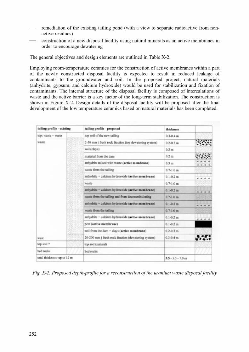
remediation of the existing tailing pond (with a view to separate radioactive from non-
active residues)
construction of a new disposal facility using natural minerals as an active membranes in
order to encourage dewatering
The general objectives and design elements are outlined in Table X-2.
Employing room-temperature ceramics for the construction of active membranes within a part
of the newly constructed disposal facility is expected to result in reduced leakage of
contaminants to the groundwater and soil. In the proposed project, natural materials
(anhydrite, gypsum, and calcium hydroxide) would be used for stabilization and fixation of
contaminants. The internal structure of the disposal facility is composed of intercalations of
waste and the active barrier is a key factor of the long-term stabilization. The construction is
shown in Figure X-2. Design details of the disposal facility will be proposed after the final
development of the low temperature ceramics based on natural materials has been completed.
Fig. X-2. Proposed depth-profile for a reconstruction of the uranium waste disposal facility
252

Table X-2. Objective and design elements.
Main Risk General Design Design Elements
Direct radiation Shielding Cover and membrane system
Tailing dispersion Long-term stability
Long-term erosion protection
Erosion protection barrier
against extreme events:
minimize the grade of the slope
vegetate cover
Water contamination:
surface water
groundwater
Isolation of tailing:
seepage barrier
erosion protection
radionuclides traps
heavy metals traps
Infiltration barrier:
top
internal
bottom
Radon emanation Radon attenuation Radon barrier
X-5. RATIONALE FOR THE USE OF ROOM-TEMPERATURE CERAMICS
Various diagenetic processes have been observed in (uranium) mill tailings and it appears
advantageous to exploit and stimulate these processes for the long-term stabilization of the
tailings. During microscopic studies, the following minerals have been recognized: quartz, K-
feldspar, plagioclase, biotite, muscovite, chlorite, amphibolite group and clay minerals,
calcite, dolomite, epidote, fluorite, garnet, gypsum, magnetite, haematite, goethite, pyrite,
chalcopyrite, pyrrhotite, barytes, rutile, anatase, sphen, and zirconium. Clay minerals are
evidence for decomposition of plagioclase and K-feldspar in an acidic environment, and are
responsible for cementation of terrigenous materials. The presence of goethite and haematite
suggest a quick oxidation of various minerals. These types of natural processes are well
known as limonitization, which is also responsible for cementation. Presence of sulfides
within the residues trigger powerful oxidation reactions. During such reaction, S-
is converted
into S6+
. This ion can very easily form acidic environment [X-3]. This is the beginning of
numerous diagenetic processes such as kaolinitization, illitization, anhydritiztion and
silicification. All these processes are responsible for the creation of local geochemical
environments. The reactions proceed until an equilibrium between stable phases is reached.
These were the basis for the selection of natural cements. The most common natural cements,
such as anhydrite, gypsum, lime (or calcium hydroxide) have been included. All these
materials have no or little environment impact. Their physical properties, such as bulk
permeability, physical strength, and their low price are important factors considered in their
selection. These materials can be named low-temperature natural ceramics.
Finely dispersed uranium minerals are oxidized quickly with the release of uranyl ions that
can migrate away from the tailings. Reduction processes, to the contrary, typically lead to the
fixation of uranium in solid phases with comparatively low solubility. Uranium precipitates
typically within the pH-range between 6.5 and 8.5 pH and the Eh-range between 0 and -0.4 V.
According to Eh-pH diagrams (system U-C-O-H, 25°C, 1 bar), UO2(s) is stable over the whole
range of pH and depends only on Eh, that is –0.4 to +0.1 V for acidic environments and below
–0.4 V for alkaline environments [X-4] BaSO4(s) and RaSO4(s) are stable under similar
conditions (usually 3-12 pH and –0.8 up to +1.2 Eh). The redox boundary (between FeS2(s)
and Fe2O3(s)) runs through the middle of the stability field of UO2(s) [X-4].
253

Precipitation of uranium within the tailing can fix free uranyl ion in new, stable phases that
would be in equilibrium with existing mineral phases and newly precipitated sulphates, iron
hydroxides and clay minerals. Freshly precipitated iron hydroxides have highly active
surfaces that can scavenge heavy metal and other cations. This type of reaction, which is often
observed in the natural environments, is the basis of the project, and a model for stabilization
of uranium mining and milling residues. In the proposed model for the remediation of tailings,
attention is paid to the sulfate concentrations. Sulfates are a stimulator of dissolution
processes. Sulfides are common constituent of residues originating from natural uranium ores.
According to Wisotzky [X-5] a two step oxidation process is proposed. During the first step,
sulfide-sulfur is oxidized, followed by the oxidation of ferrous iron. The final results of
oxidation are similar to those presented in the equations listed below (after [X-6]).
2 FeS2 +7 O2 +2 H2O ↔ 2 FeSO4 + 2 H2SO4 (1)
Ferrous sulfate is instable in the oxidized zone and is converted to:
12 FeSO4 +6 H2O + 3O2 ↔ 4 Fe2(SO4)3 + 4 Fe(OH)3 (2)
Ferric sulfate is usually unstable under oxidising conditions and is subject to hydrolysis
according to equation:
Fe2(SO4)3 + 6H2O ↔ 2Fe(OH)3 + 3H2SO4 (3)
During the oxidation, an active iron-hydroxide gel is produced. Then, this gel is dehydrated
and converted into limonite (mixed compound), monohydrate (goethite = FeOOH), hydro-
hematite (Fe2O3·½H2O), and haematite (Fe2O3). Such reactions occur in a neutral or weakly
acidic environment.
The effects of redox reaction have been observed at the Kowary tailing oxidation of iron that
consumes an extra charge. In the course of these reactions, the solid phases of iron hydroxide
(goethite) and haematite, as well as gypsum are formed.
The oxidation of iron, consumes an extra charge, will be creating an environment conducive
to the reduction of UO2
2+
to UO2. The thus obtained pitchblende is quite stable in normal
(surface and subsurface) oxidising and locally anoxic environments. In order to minimize
dissolution of UO2 by sulfuric acid formed according to reactions (1) or (3), the construction
of an active membranes containing calcium oxide or hydroxide is recommended. These
compounds will react with any free acid by forming gypsum.
As a result of the oxidation, various elements can be mobilised from the mining residues, but
radium remains associated with sparsely soluble phases such as Ca-, Ba- or Sr-sulfates.
Radium solubility is very low under normal conditions. Hence, radium is usually precipitated
together with the earth-alkaline elements, forming insoluble sulfates as a first solid
precipitate. Barium-radium sulfates are well known from mine waters of some hard coal
mines, as well as uranium mines. To ensure that the radium remains in the residues, it is
proposed for the construction of the new disposal facility to use modified anhydrite and
calcium hydroxide as components of the internal active membranes.
A key problem for the proposed remediation project is the stabilisation of pH in order to
maintain a suitable environment for the oxidation and cementation (fixation) reactions. To
achieve this proper environment and the stabilizing reactions, a special design for the disposal
facility is proposed. It consits of intermixed layers of residues and barrier components,
254

composed of natural materials. The presence of CaO or Ca(OH)2 and anhydrite in the internal
membrane will reduce vertical migration of sulfates. Redox reactions will be responsible for
secondary precipitation (reduction) of uranyl anions. Similar reactions are responsible for the
formation of uranium deposits.
The addition of calcium hydroxide as proposed for construction of the active membrane,
should buffer pH in the near-neutral area. Active solidification of waste pile will be running
successively with redox reaction due to natural cementation of sandy-clay waste fraction with
natural precipitated phases [X-7]. These is a good probability for long-term stabilization of
radio nuclides with the proposed construction method for the tailings.
Sorption can also be an important factor for reducing migration of some radionuclides and
other pollutants. Sorption of uranium and other contaminants occurs on iron and silica gels
thus reducing the contamination of groundwaters.
X-6. MINERALOGICAL ANALYSES
The mineralogical composition of the mining residues was determined using an ore
microscope and XRD. Under the microscope, pan concentrates obtained from two visually
distinctive types of residues have been studied. The XRD analyses were carried out on fine-
grained material (clay fraction) separated from the mining residues. The fine fraction of the
residue was obtained by suspending the material in distillated water. After four hours of
sedimentation, the supernate containing the clays in suspension was collected and then dried.
Radium activities were measured at the Faculty of Physics and Nuclear Techniques of the
University of Mining and Metallurgy in Kraków using gamma spectroscopy.
X-7. ASSESSMENT OF RADON EMANATION
X-7.1. Conceptual appraoch
Radon is a natural radioactive element in gaseous form. It is a decay product of radium, which
is present in many rocks and building materials. Radon escapes from these via diffusion and
convection. The radon release from solid materials to the air-filled pore space is known as
emanation. The parameters that characterise quantitatively this effect are the emanation
coefficient and/or exhalation rate [X-8]. The emanation coefficient expressed as percentage,
is defined as a ratio of the number of Rn atoms released from the solid phase into the pore
space to the total number of Rn atoms that produced by the Ra-decay. The exhalation rate is
defined as an exhaled radon activity per mass or surface unit of a sample per unit of time.
The radon activity N1 [Bq] produced by the radium activity in the investigated material sample
is calculated by the following equation:
)1(1
1
tRn
emRaN
λ−−×= (4)
where: Ra is an activity concentration of 226
Ra in the investigated material in [Bq/kg], λRn –
decay constant of Rn, m – the mass of the material sample [kg] and t1 – a time of the build-up
of radon activity inside the emanation chamber from a material sample.
A relative exhalation rate R in percentage is defined as the ratio of the measured radon
activity exhaled from a sample to the total radon activity emanating from it.
255

%100
1
N
N
R = (5)
The mass exhalation rate Em [Bq⋅kg
–1⋅h-1
] may be calculated by equation 6:
))exp(1(11
1
tm
N
Em ⋅−−⋅
⋅=λ
λ (6)
And the surface exhalation rate Es [Bq⋅m-2⋅h-1
] is expressed as followes:
))exp(1(11
1
ts
N
Es ⋅−−⋅
⋅=λ
λ (7)
where m and s are the mass [kg] and the area [m2
] of the sample and the rest of symbols are
the same as above.
X-7.2. Analytical methods
For the determination of the emanation rates, a chamber with the dimensions of 20 × 20 × 25
cm (10 dm3
) was used. A sample with a volume of about 0.5 dm3
is hermetically enclosed in
the chamber. Depending on the kind of a investigation, the time the sampling time ranges
from a few days to 30 days. This time period is selected so as to ensure enough Rn being
emanated. Then a gas sample of of 100 cm3
is extracted from the emanation chamber through
a valve into a syringe. The gas sample is mixed with 40 cm3
of a liquid scintillator in a glass
tube of 2 cm diameter and 25 cm length. Next, the scintillator mixture is divided into counting
vials of 22 cm3
volume and the count rates are determined by α⁄β liquid scintillation counter3
hours after the extraction of the gas sample. The contents of 226
Ra in the samples is
determined by a gamma-ray detection system with a NaI(Tl) scintillation crystal or a semi-
conductor detector. The radioactive equilibrium between 226
Ra and 214
Bi was maintained by
tight sealing of the samples and keeping them for 32 days so that radon could not escape.
X-8. POTENTIAL LEACHIBILITY OF RADIUM ISOTOPES
X-8.1. The problem
Under ambient environmental conditions, generally radioactive residues associated with
uranium deposits appear to be highly stable and very insoluble. However, radium co-
precipitated in a sulfate matrix is not thermodynamically stable under reducing conditions and
it could be released to the environment.
The question of leachability of radium isotopes from contaminated materials exposed to acid-
rain and other ageing processes is generally unknown. The leachability of radium from
contaminated soil was investigated using fluids having wide range of pH, reflecting different
and more extreme chemical parameters.
X-8.2. Leach tests
An aliquot of approximately 50 g of contaminated soil was mixed with an extraction fluid at a
1: 20 solid-to-liquid ratio for approximately 72 h according to the ASTM D5284-93 standard
method for sequential batch extraction [X-9]. The soil and extraction fluid were mixed
together in 1 lpolypropylene bottles that were tumbled end-over-end throughout the extraction
period using a tumble mixer. After mixing, the extraction fluid was filtered through a 0.45 µm
256

pore size membrane filter. Then the radium contained the extracted fluid was precipitated and
measure by liquid scintillation counter. The procedure of sample preparation procedure and
measurement of radium isotopes is described in more detail elsewhere [X-10].
The leaching potential is defined as the percentage of the original 226
Ra content of the sample
measured in the leaching solution after contact with the soil for a period of 72 h.
A procedure to simulate natural leaching conditions was devised: the Ra-content of prepared
samples were measured , then these samples were buried at a depth of 0.5 m in a natural
environment. To this end, all samples to be tested were transported back to the Kowary
Podgórze village, to a bury place close to the uranium mine and tailings deposit. This place
was located on the slope of the existing dumps, containing uranium minerals. The samples
were left for a period of 10 months, i.e. through winter-spring- summer. After this period of
time, the samples were dug up, cleaned, dried and measured again for their Ra-content.
X-9. ANALYTICAL RESULTS
X-9.1. Mineralogical composition of the residues
Macroscopically, two different types of waste have been identified. The first type is a sandy
fraction (below 2 mm) located within an internal part the waste disposal site. The second type
of waste has been found on the southern slope of the tailing dam. It is coarse grained fraction,
probably obtained at mineral plant of the former iron mine. In comparison to the other type of
waste, this waste is characterized by higher amounts of magnetite and haematite. A full list of
the minerals identified is given in Table X-3.
Table X-3. Mineralogical composition of the residues (minerals
in bold are responsible for cementation)
Major Minerals Minor Minerals
quartz magnetite
K-feldspar haematite
plagioclase goethite
biotite pyrite
muscovite other sulphides
chlorite baryte
amphibolite group rutile
clay minerals anatase
calcite sphene
dolomite zircon
epidote
fluorite
garnet artificial phases, glass and slag
gypsum
During microscopic observation evidence for pyrite and magnetite oxidation has been found.
It is clear that the more recently deposited tailings can be treated as a classic sediment and that
the well-established concepts of diagenesis can be applied to them. The role of diagenetic
processes is very important for planning of long-term stabilization of waste disposal facilities.
In the course diagenetic processes, free uranium can be easily incorporated into iron
257

hydroxides and adsorbed on their active surface. Decomposition of feldspars will play also an
important role. Free oxygen is responsible for an initiation of pyrite oxidation in the residues.
The free sulphuric acid produced during this reaction may lead to the decomposition of the
feldspars. As a result of feldspars decomposition, new clay minerals will be precipitated,
which then can adsorb free uranyl anions.
Two types of materials deposited in the tailing pond can be distinguished by their
radionuclide composition (Tab. X-4). The first one is characterized by a lower radium
activity, ranging between 3,200 – 3,820 Bq·kg-1
. The total radium activity of the second type
residue is by about 2,000 Bq·kg-1
higher (compare Tab. X-3).
Sample SP6 was obtained mixing sample SP1+SP2+SP3+SP4+SP5 (see Tab. X-4).
Table X-4. Radionuclide contents of different types of residues from the
uranium tailing at Kowary Podgórze (by gamma spectroscopy).
Sample40
K [Bq·Kg-1
]226
Ra [Bq·Kg-1
]232
Th [Bq·Kg-1
]
SP1 1,330±200 3,240±100 10±10
SP2 1,420±200 3,820±100 10±10
SP3 1,290±300 5,780±200 20±10
SP4 8,70±300 5,670±200 30±10
SP5 7,70±200 3,260±100 90±10
SP6 1,030±500 4,210±300 6±6
X-9.2. The mineralogy of ‘room temperature ceramics’
Natural materials have limited application to the physical stabilization of waste because of
poor knowledge of in-site reaction. Study and selection of materials is required before
application. Reaction with a natural substances are running relatively slowly, however when
the processes are completed achievements in litification are much better than other artificial
relevant. Some natural cements and their characteristic are presented in the Table X-5.
X-9.3. Physical parameters of some samples used in the experiment
Some geotechnical and hydraulic parameters relevant for the stabilisation and fixation of the
sandy fraction of the residueshave been determined (Tabs. X-5 and X-6). All measurements
were carried out by Dr. J. Mazurek from the Dept. of Geomechanics, Civil Engineering and
Geotechnics, AGH Kraków, Poland.
The experimental sample (SP6) mixed with modified anhydrite showed low compressive
strength in comparison to materials normally used for construction. After water absorption
capacity measurements, all these samples were damaged. However, they cannot be neglected
as a cements for the waste fixation. Field test showed that these samples hold well their
properties after 10 month of storage in the local environment. The local environment at the
chosen testing place is characterized by a wide temperature range (from +35°C to-35°C), high
annual precipitation rate (1500 mm/y), and slope angle steeper than 10°. Physical parameter
measurements showed also that the way of preparaing the samples plays an important role.
258

Parameters such as porosity, compressive strength, and Young modulus were basis of sample
selection, however further experiments with bigger sample sizes are needed.
Table X-5. Characteristics of different natural materials that could be used for the long-term
stabilization and isolation of low-level uranium residues.
Material Advantages Disadvantages
clays:
kaolinite, illite,
bentonite
montmorillonite,
mixed phases
(smectites)
• very good sorption capacity
• good water retention
• simple technology of application.
• very often occur in the big quantity in
the nature
• low price
• mono-mineralic clays are rare in nature,
• possible desorption
• changes during diagenesis
• -chemical modification may be required
carbonates:
calcite, dolomite,
magnesite, siderite
• pH buffering,
• very common in nature
• reasonable price
• cementation effects
• useful for ARD treatment
• not useful in the alkaline treatment processes
• grinding is required
sulfates:
gypsum, anhydrite,
barytes
• γ-shielding (barytes)
• Rn-shilding (gypsum, CaSO4×0.5 H
2O)
• conversion of anhydrite to gypsum
• occur in good quality and quantity in
nature
• reasonable price
• reconversion of gypsum to anhydrite in the
presence of NaCl-waters
• grinding is required
bauxite • high sorption parameters
• occurs in a few areas only
• reasonable price
• limited occurence
diatomites • very high sorption capacity
• low density
• reasonable price
• very rare in nature
Fe-hydroxides • very high sorption capacity
• occur in a few areas only
• reasonable price
• modification may be required
red soil • high sorption capacity
• occurs in some areas
zeolites • very high sorption capacity • grinding is required
• rare in nature
hydroxyl apatite • very high sorption capacity
• expensive
• grinding is required
• very rare occur in nature in high quantity
quartz:
gravel and sand
• good drainage
• occurs only at some places
• reasonable price
• sorting/grading is required
carbonate gravel • drainage
• pH buffer
• useful against ARD
X-9.4. Radon exhalation rates from conditioning mixtures
Calculated values of the relative, mass, and surface exhalation rates of the samples taken from
the uranium tailing piles are presented in Table X-8. These results show that samples have
relatively small exhalation rate E. Among the tested materials, mixtures of SP6 with natural
cement (anhydrite, gypsum) have the lowest exhalation rate.
259

Table X-6. Water absorption capacity mesurements according to polish standard pn-66/b-
04101.
Mass of
dry
sample
Mass of
saturated
sample
Sample
volume
Dry
density
Mass of
adsorbed
water
Volume of
adsorbed
water
m m1 v C
o n
w n
o
Sample
[g] [g] [cm3
] [g·cm-3
] [%] [%]
Remarks
0.9 SP6 +
0.1 lime
169.60 208.78 120.19 1.41 23.10 32.60
After 72 h some disinte-
gration was observed
0.7 SP6 +
0.3 gypsum
159.49 218.47 129.81 1.23 36.98 45.44
No change
0.8 SP6 +
0.2 gypsum
162.85 215.08 123.63 1.32 32.07 42.25
sample broke at ½ of its
height. The depth of
fissure was ½ of sample
diameter. Some additio-
nal disintegration was
observed.
0.9 SP6 +
0.1 cement
190.67 228.21 121.29 1.57 19.69 30.95
No change
0.8 SP6 +
0.2 cement
197.59 237.18 124.25 1.59 20.04 31.86
No change
0.7 SP6 +
0.3 cement
200.22 243.75 125.96 1.59 21.74 34.56
No change
Table X-7. Geotechnical parameters of some samples used in the experiment
Height Everage
surface
Compressive
strength
Young
modulus
h S Rc E
Sample
[mm] [mm2
] [Mpa] [Mpa]
Remarks
0.9 SP6 + 0.1
lime
49.20 2397.87 0.60 30
Irregular shape, some grains
were crumbling away
0.7 SP6 + 0.3
gypsum
50.50 2643.85 0.47 30
Regular shape, some grains
were crumbling away
0.8 SP6 + 0.2
gypsum
51.70 2488.69 0.28 17
Irregular shape, some
fissures were observed, and
some grains were crumbling
away
0.9 SP6 + 0.1
cement
49.35 2457.65 1.55 102
Regular shape
0.8 SP6 + 0.2
cement
49.75 2487.52 4.87 450
Regular shape
0.7 SP6 + 0.3
cement
49.85 2535.08 11.41 1320
Regular shape
260

Table X-8. Relative, mass and surface exhalation rates measured for sample SP6 and various
admixtures of binders to this material.
Sample Mass of
sample (σ)
226
Ra (σ) R (σ) Em
(σ) Es (σ)
[g] [Bq·kg-1
] [%] [Bq·kg-1⋅h-1
] [Bq·m-2⋅h-1
]
SP6
904.22 (5) 4210 (80) 10.95 (6) 3.48 (18) 147 (15)
0.9 SP6 + 0.1 cement 998.39 (5) 3800 (70) 15.3 (8) 4.39 (22) 243 (12)
0.7 SP6 + 0.3 cement 1046.05 (5) 2950 (80) 17.1 (9) 3.81 (17) 211 (10)
0.9 SP6 + 0.1 anhydrite 959.45 (5) 3790 (70) 11.76 (8) 3.36 (11) 186 (25)
0.7 SP6 + 0.3 anhydrite 975.9 (5) 2950 (90) 4.29 (27) 0.83 (5) 46.1 (22)
0.9 SP6 + 0.1 gypsum 885.80 (5) 2966(100) 9.00 (6) 2.01 (11) 112 (6)
0.7 SP6 + 0.3 gypsum 861.41 (5) 2840 (80) 1.04 (4) 0.223 (2) 12.3 (7)
σ – standard deviation
X-9.5. Results of leach tests
The quantity of 226
Ra leached from the SP6 sample depends on chemical composition of
solvent used in the experiment. In the Table VI are shown results of leaching test. Leaching
potential of normal water is very low, but increasing of NaCl content in the water can rapidly
change condition of the leaching (Tab. X-6).
Table X-9. Results of 226
Ra leaching from samples of low-waste uranium using different
extraction fluids.
Sample Extraction fluid
Leaching potential
[%]
Specific activity
[Bq·kg-1
]
SP6 water 0.16 4100
SP6 Water + NaCl (100 g·dm-3
) 4.8
SP6 Water + Na2S (1 g·dm-3
) 0.07
X-9.6. Results of experiments simulating natural leaching conditions
The 226
Ra activity of samples after 10 month burial in the Kowary Podgórze environment
(close to the uranium residues dump) is reduced by 0.6% to 6.2% compared to activities
before burying (Tab. X-10). The data suggest a small loss of radium over the period of 10
months, but the measured differences are only slightly above the statistical errors. It suggests
that in the testing environment with a pH similar to the one measured in the tailing pond,
radium can be trapped within the residues cemented by selected natural cements.
The experiment showed that the natural cements (calcium hydroxide can be replaced by
calcite or limestone) could play a significant role in the stabilisation of radionuclides in the
system proposed for a new milling residue storage facility (see Table X-11).
261

Table X-10. 226
Ra, 232
Th specific activity of selected materials prepared on the
base of materials from Kowary tailing pond.
Specific Activity (σ) [Bq/kg]
Sample 226
Ra 223
Th
SP6 4170 (80) 6 (6)
0.70 SP6 + 0.30 cement 2581 (80) 21 (8)
0.70 SP6 + 0.30 gypsum 2840 (90) 13 (10)
0.70 SP6 + 0.30 anhydrite 2950 (90) 12 (10)
Anhydrite 9 (2) 2 (2)
Hydrated lime 19 (3) 2 (2)
Gypsum 8 (2) 2 (2)
Cement pure 73 (6) 30 (3)
0.60 SP6 + 0.40 anhydrite 2440 (50) 15.5 (10)
0.90 SP6 + 0.10 cement 3750 (70) 25 (8)
σ- standard deviation
Table X-11. Change of specific 226
Ra activities of the selected materials after 10 month
deposition underground.
Specific 226
Ra activity (σ) [Bq/kg] Activity ratio
Sample
before deposition after deposition (σ)
0.7 SP6 + 0.3 cement 2581 (80)a
2461 (50) 0.953 (36)
0.7 SP6 + 0.3 gypsum 2840 (90)a
2799 (56) 0.979 (35)
0.7 SP6 + 0.3 anhydrite 2950 (90)a
2932 (58) 0.993 (34)
0.9 SP6 + 0.1 cement 3750 (70)a
3566 (70) 0.942 (37)
0.9 SP6 + 0.1 calcium hydroxide 3750 (70) 3610 (72) 0.962 (35)
0.9 SP6 + 0.1 anhydrite 3750 (70) 3750 (73) 0.981 (35)
0.8 SP6 + 0.2 gypsum 3340 (65) 3277 (65) 0.997 (34)
0.8 SP6 + 0.2 anhydrite 3340 (65) 3240 (63) 0.970 (34)
0.9 SP6 + 0.1 cement 3810 (70) 3570 (72) 0.942 (37)
0.8 SP6 + 0.2 cement 3350 (65) 3240 (65) 0.967 (34)
a
calculated on the base of material content; σ – standard uncertainty
X-10. DISCUSSION
Investigation of the mechanical properties of some natural ‘ceramics’ used in the experiments
showed that they are good materials for fixation and solidification of residues. They can also
262

play an important role in the chemical stabilisation. The advantage of the natural materials is
that they can be easily assimilated in the environment, and their porosity is lower compared to
those samples treated with Portland cement. A decrease in of the porosity of the waste pile
reduces the radon flux. Moreover, all residues contain various clays, and such material cannot
be cemented with Portland cement. Natural cements should be selected by their mineralogical
composition and considering the geochemical properties of the waste. The active membranes
proposed, especially those containing lime or calcite, would stabilize the pH-values within the
proposed new waste disposal facility. Natural zeolites, which have not been investigated
experimentally because of lack of time, could also be considered for the construction of
bottom and top isolation membranes (see also table X-5).
Leaching and field tests showed that natural cements can be used for trapping radionuclides
within the the disposal facility. A mixture of modified anhydrite powder with gypsum and
hydrated lime can be proposed for the construction of the internal, active membranes (cf. Fig.
X-2). However, the final composition of the active membrane should be selected to fit the
mineralogical composition of the residues. The proposed mineralogical membrane could
actively react with both fluids and residues. A chemical fixation would only be successful, if
the system of proposed mineral membranes can create a geochemical equilibrium within the
waste pile.
X-11. SUMMARY AND CONCLUSION
Room temperature ceramics (natural cements) have been tested in the laboratory for both
cementation capabilities of milling residues and effectiveness in reducing the radon
emanation. Positive results of litification obtained using mixtures of modified anhydrite
powder (typical used in construction), anhydrite powder mixed with Portland cement,
anhydrite powder mixed with calcium hydroxide with residues (SP6) from the Kowary tailing
pond. Some physical measurements, 226
Ra activity, Radon flux and leaching test have been
undertaken with such prepared testing samples. Measurements of physical parameters showed
that small admixtures of natural cements (ceramics) could easily fix the sandy and clay
fraction of the residues.
The new environment in the place of the new storage for the waste is also a critical stage of
the experiment. After litification of active membranes within the new waste disposal, the
control and modification of pH and Eh will be very limited.
ACKNOWLEDGEMENT
The project has been partly supported by the Polish National Science Foundation (KBN),
AGH no. 11.11.140.258. We especially thank dr. J. Mazurek from Dept. of Geomechanics,
Civil Engineering and Geotechnics, AGH Crakow for his help during laboratory works.
REFERENCES TO ANNEX X
[X-1] PIECZONKA, J., PIESTRZYŃSKI, A., CHRUŚCIEL, E., JODłOWSKI, P.,
“Uranium deposits and their impact on local environment”, Polskie Towarzystwo
Mineralogiczne, Spec. Pap. 16 (2000) 169–190 (in Polish).
[X-2] PIESTRZYŃSKI, A., PIECZONKA, J., MIELNICZUK, W., CHRUŚCIEL, E.,
JODłOWSKI, P., “Effects of uranium mining on the contamination of some areas in
263

Poland”, in: Planning for environmental restoration of radioactively contaminated
sites in central and eastern Europe, IAEA-TECDOC-865, Vol. 1, Vienna (1995)
193–216.
[X-3] BANAŚ, M., MOCHNACKA, K., “Genetic types of uranium mineralisation in
Poland and their metallogenic relationships”,In: Metallogenesis of uranium deposits
more details, Panel Proceedings Series, IAEA Vienna (1989) 187–200.
[X-4] BROOKINS, D.G., Eh-pH Diagrams for Geochemistry, Springer Verlag, Berlin etc.
(1988) 176 p.
[X-5] WISOTZKY, F., “Redox reactions, Multi-component stability diagrams and isotopic
investigations in sulphur- and iron-dominated groundwaters systems”, In
SCHÜRING, J., SCHULZ, H.D., FISCHE, W.R., BÖTTCHER, J., DUIJINISVELD,
W.H.M. (Eds.) Redox Fundamentals, Processes and Applications, Springer,
Heidelberg (2000) 251 pp
[X-6] SMIRNOW, S.S., Oxidation zone of sulphide deposits, Wydawnictwa Geologiczne
Warsaw (1956) 1–316.
[X-7] PIESTRZYŃSKI, A., PIECZONKA, J., CHRUŚCIEL, E., “Model for long-term
stabilization and isolation of low level uranium waste”, The 8th
Interanational
Conference on Radioactive Waste Management and Environmental Remadiation,
ICEM 2001. Brugge, Belgium, (2001) 1-5
[X-8] ŻAK A., BIERNACKA M., MAMONT-CIEŚLA K., Investigations of radon and
thoron emanation from building walls, Nukleonika, 38 4 (1993) 39–50.
[X-9] AMERICAN SOCIETY FOR TESTING AND MATERIALS, “Standard practice
for soil preparation for the determination of radionuclides”, Annual book of ASTM
standards, Philadelphia. PA (1993) C999-90.
[X-10] NGUYEN DINH, CHAU, CHWIEJ, T., CHRUŚCIEL, E., 226
R, 228
Ra and 210
Pb
isotopes in some samples of mine water”, J. Radioanal Nuclear Chem., 250(2),
(2001) 387–390.
264

ANNEX XI. RUSSIAN FEDERATION
POLYMERIC COATS FOR THE STABILISATION OF CONTAMINATED
SURFACES
S.V. Mikheykin
A.A. Bochvar Institute of Inorganic Materials, Chemical Technology Department,
Russian Federation
XI-1. ABSTRACT
VNIINM has been developing remediation techniques for contaminated sites as a result of
nuclear accidents since 1986. An approach, based on basic science approach (radiochemistry,
radionuclide migration, soil science, synthesis of polymers, etc.), was used to develop
specialised technologies for the remediation of contaminated sites. This approach uses
synthetic polymers to sequester radionuclides. Ecologically safe polymers and procedures for
soil decontaminations were developed and tested. This technology also fosters the formation
of a protective grass cover by providing structure formers.
The new polymeric compositions prevent soil erosion by water and wind with an efficiency
over 95 % and a 1-3 year stability to atmospheric influences. Techniques for laboratory and
field testing were developed; water and wind erosion test of soil with various polymeric
structures are carried out.
XI-2. INTRODUCTION
Dispersion of radioactive substances from the surface of tailings ponds and waste rock piles
due to water and wind erosion is a significant problem faced by the relevant industries.
Disposal, long-term stabilisation, and isolation of uranium mill tailings requires the
development of adequate technologies. The effect of atmospheric factors (rainfall, snow-melt,
and wind) on contaminated areas can cause secondary contamination of the environment.
Currently, with a view to long-term stabilisation of such territories, multibarrier concepts have
been developed that genrally consist of covers made up of crushed rock, sand, and soil.
The project suggests applying supplementary protection against water and wind erosion,
namely polymeric structure formers based on interpolyelectrolite complexes (IPEC). These
polymers have been successfully tried and applied on an industrially scale to suppress
radioactive dust generation after the Chernobyl accident.
Tailing pulps usually consists of solid particles in the 0.225-0.1 mm size range, while
particles with weighted mean size of 0.08 mm are typical tailings beach areas. The finely
divided materials (<10 µm) are readily swept away great distances as aerosols at an initial lift
rate of 3-5 m/s to cause airborne contamination, with air particle concentrations exceeding
standards by tens of times. This presents a serious inhalation hazard. The polymers are able to
resist the action of natural factors on top soils, thus providing a supplementary protective
barrier.
XI-3. ACTIVITIES UNDER THE PROJECT
The following main activities were undertaken in this project:
265

(1) Analysis of existing means of protection and remediation, polymeric preparations used,
depending on natural factors, soil types and types of contamination;
(1) Selection of a method of protecting contaminated surfaces with polymeric coatings as a
function of the given conditions;
(2) Development of laboratory testing procedures;
(3) Testing of polymers with real and surrogate waste materials;
(4) Research on the effect of polymer coatings on to development of grass vegetation;
(5) Recommendations for applying polymer covers to uranium mill tailings.
XI-4. POLYMERS AND THEIR APPLICATION
XI-4.1.Synthesis of polymers
It is well known that the bulk of radioactivity is accumulated on the fine particles and the
organic fraction of geological materials. This size fraction is found to be the most susceptible
to dust generation and erosion
One possible way of stabilisation/fixation is to create additional bonds based on water-
insoluble high molecular weight compounds. Similar compounds (trade marks MM-1, MJ-1)
based on interpoly-electrolyte complexes (IPEC) have been developed by VNIINM and
Moscow State University (MSU) to immobilize radioactivity captured by soils following the
Chernobyl accident (1986-1993), and for another contaminated site remediation purposes.
IPECs are the products of interactions between oppositely charged macromolecules [XI-1].
The interpolyelectrolyte reaction proceeds by the following mechanism:
COO Na
COO
COO
Na
Na
N
N
N
Cl
Cl
Cl COO
COO
COO
+
N
N
N
+ NaCl
(XI-1)
IPECs can be considered as intelligent (smart) materials, due to their ability to adapt
themselves to complex structures of dispersed systems via rapid exchange processes and to
attain the optimal set of bonds with different colloidal particles and surfaces. A new
generation of IPEC structure formers with microgels (MLA-1, MLA-2) was developed in
VNIINM and MSU. They have not only a high efficiency in fine particle stabilisation, but
also high ability to support grass vegetation during remediation activities.
XI-4.2.The soil-polymer layer formation
The technology for preparing and applying IPECs is quite simple. It involves (i) the
preparation of dilute aqueous polyelectrolyte mixtures where ionic interactions between
oppositely charged polyions are completely suppressed. (ii) the application of these aqueous
solutions as dispersed systems usually by spraying; (iii) washing of the dispersed systems by
water in order to remove mineral salts. The commercially made synthetic and natural
constituents are non-toxic [XI-2-XI-9].
The main objective of IPEC application is a good interaction between the small negative
charges on mineral surfaces (resulting from the dissociation of silanol Si-OH groups) and the
polycation forming part of IPEC. The joint application of polications and polyanions result in
formation of long-term stable surface-polymer complex (Fig. XI-1).
266

The IPEC treatment of soils produces a polymer coating 3-6 mm thick, which tightly binds
the fine grains to each other by way of aggregation of small particles and by coagulation of
soil colloids.
Fig. XI-59. Formation of protective polymer coatings.
XI-5. LABORATORY TESTS
XI-5.1.Samples
During the period of 2001 – 2003 the polymeric structure formers were successfully tested
under laboratory conditions and in the field with material from a mill tailings beach of the
Ulba Metallurgical Plant (Kazakhstan, see Annex VII), and in the laboratory with surrogate
tailing materials from Zovtny Vody (Ukraine, see Annex XII).
XI-5.2.Characterisation of Ulba samples.
For the tests we used actual samples from Ulba. It was loose material of 5.0 kg in mass. The
initial moisture content was 18%. Prior to the investigations the material was dried to the air-
dry conditions. The results of the sieve analysis are summarized in Table XI-1 and an.
external view of the samples is given in Fig. XI-2.
The chemical composition and and the grain-size distribution of actual samples from Zovtny
Vody and the surrogate material are given in Tables XI-2 and XI-3.
267

Fig. XI-60. View of Ulba tailings preparing for laboratory tests.
Table XI-20. Grain size distribution of tailings from Ulba Metallurgical Plant.
Sizes class [mm] Content [%]
>1 1.9
1 >0.63 9.4
0.63 >0.4 10.9
0.4 >0.315 9
0.315 >0.2 19.1
0.2 >0.1 38.2
0.1 > 0 11.5
Total: 100.0
Table XI-21. Chemical composition of Zovtny Vody model samples [solid wt %].
Composition Actual Model Composition Actual Model
SiO2 59,3÷64,0 62.0 ZrO 0,10÷9,13 5.8
Fe2O3 2,4÷3,84 2.7 PbO 0,010÷0,012 0.0
FeO 0,58÷1,67 0.9 CaO 2,0÷3,26 2.6
MgO 0,87÷1,82 0.0 TiO2 0,29÷0,37 0.3
Na2O 7,87÷11,6 10.1 Al2O3 15,38÷16,8 15.6
K2O 0,48÷0,8 0.0 P2O5 0,17÷0,40 0.0
Stotal 0,04÷0,09 pH 8÷9
Table XI-22. Grain size distribution of actual Zovtny Vody and model samples.
Size class [mm]
Content [wt %] >0.25 0.25 >0.14 0.14 >0.10 0.10 >0.074 0.074 >0.04 >0.04
actual 1.0 5.4 8.7 9.8 15.3 59.8
model 0.95 5.6 8.5 10.1 14.1 60.75
268

Fig. XI-61. Soil particles plus polymeric film.
Fig. XI-62. Particles conglutination by
polymer
Fig. XI-63. Long polymeric bridge with
particles.
Fig. XI-64. Glueing of small particles onto
big ones by polymer.
Fig. XI-65. Electron microphotograph.
Fig. XI-66. Electron microphotograph.
269

XI-5.3.Structure of Polymeric crusts
The microstructure of protective soil-polymer layers has been studied by light microscopy.
Fine particles are attached to each other as a function of the polymer nature and amount:
(1) by a solid polymeric film (Fig. XI-3). Whatever its size, each sandy particle is
enveloped with the polymeric film that also fills the spaces between them to form a
solid thick waterproof layer (this would require a 5-10 fold greater amount of polymer
compared to the 1 l/m2
dosage of IPEC needed otherwise);
(2) at points of particle contact (Fig. XI-4). Spaces between particles are free, allowing the
movement of water and air;
(3) by thin bridges (Figs. XI-5 and XI-7), when particles of different size are separated by a
considerable distance (from 1 mm to 1-2 mm);
(4) due to small-size particles (5-20 mm) sticking to larger ones(over 700 mm) (Figs. XI-6
and XI-8). This occurs during the evaporation of the polymeric solution covering the
particles. The fine particles are picked up by the solution from interspaces and attached
and attracted by large particles.
The soil particles are attached to each other only at intergranular contacts or by polymeric
bridges. Owing to this, the IPEC-treated soil remains penetrable to moisture and air. The
bonding decreases the wind and water erosion of small particles on which the bulk of the
radioactivity is located. In addition, because the IPEC have free functional groups, it has been
found to form strong complexes with aqueous radionuclides species.
XI-5.4.Wind erosion of contaminated surfaces
XI-5.4.1. Wind tunnel tests
Treated samples were subject to erosion test in a wind tunnel. The facility (Figs. XI-9 and XI-
10) consists of a stainless steel (1Kh18N10T) body which encloses removable containers of
different size that are to be filled with the samples to be tested, an air filter to trap particles in
the air supply, a dust collector for the particles eroded from the sample surface, and a vacuum
pump (NT 700 KARCHER with a maximum output of 94 l/s at 218 mbar).
Samples were placed in the rectangular container, rolled smooth and slightly compressed. The
density of all specimens was a constant 1.50 g/cm3
. The samples then were exposed to an air
stream over a velocity range from 10.0 to 40.0 m/s in the wind tunnel.
XI-5.4.2. Experiment № 0 - control sample.
An untreated sample was exposed for 10 min in the wind-tunnel facility to an air flow with
various velocities between 1.74 and 10.2 m/s. The loss of mass in the course of the
experiment was 108.5 g (Figs. XI-11 and XI-12).
Intensive erosion already began at a velocity of 6.38 m/s and after increasing the velocities in
increments up to 10.2 m/s the material was almost completely carried off from the cell. This is
an evidence for the low wind erosion resistance of untreated samples.
270

Fig. XI-67. Schematic diagram of the wind tunnel.
Fig. XI-68. View of the wind tunnel.
271

Fig. XI-69. View of untreated sample before
experiment
Fig. XI-70. Appearance of untreated sample
after experiment.
Fig. XI-71. View of sample moistened with
distilled water and treated with MJ-1, before
experiment
Fig. XI-72. View of sample moistened with
distilled water and treated with MJ-,1 after
experiment
XI-5.4.3. Results from treated samples
The generation of aerosols in the 0.3-10 µm size range was studied in the wind tunnel for a
velocity range between 7.5 – 40.0 m/s. The results suggest that within the limits of
experimental accuracy and instrument range no erosion occurs at the wind speeds tested. The
maximum erosopm is not more than 0.05 g/cm2
, i.e. 60-100 times less than that for untreated
samples.
The results indicate that essentially no aerosols are produced over an intact protective coating,
but a sharp increase in their amount when the protective cover is demaged. On the strength of
the tests, we can conclude that the dust suppression technique developed is effective for wind
speeds as high as 40.0 m/s.
272

XI-5.4.4. Experiment 4 - simulation of treatment condition for real tailings.
A cell is filled with a sample dried to air-dry condition and impregnated with distilled water
from the bottom up by immersion into a vessel (simulated conditions of moist tailings
beaches). After that the moistened surface was treated with MJ-1 at a dosage of of 2.0 l/m2
.
The sample was dried at 30ºC to an air-dry state. The cell then was exposed in the wind-
tunnel to air flows at a velocity of up to 45.5 and up to 70.5 m/s (Figs. XI-13 and XI-14).
The experiment did not result in a destruction of the sample. The aerosol concentrations in the
air flow did not exceed 1-8 mg/m3
. The loss of the mass in the course of the experiment was
1.5 g. The experiment has demonstrated the high erosion resistance of the protective coating
that is formed by the polymer MJ-1.
XI-5.5.Water Erosion tests
XI-5.5.1. Theoretical considerations
Water erosion is a combination of fine particles detachment, transfer and deposition by
surface run-off and interflow. For mill tailings two sources of run-off are coneivable: rain
water or snow-melt.
The water erosion can be quantified in terms of a material removal rate, expressed as its
weight removed from a unit area (typically ton/ha) or as a thickness of the layer lost (typically
mm/year). Erosion resistance is quantitatively expressed in terms of the scouring erosion rate
(V∆рw):
V∆рw = 1,55 · ( )g
n
P
d
o
w oρρ ρ
′−
−1
100
(XI-2)
where g acceleration of gravity [m/s];
n’ coefficient, taking into consideration the pulsating character of velocities. This
coefficient is equal to 2.28 for flow in rill channel and to 1.46 for flow in a
laboratory channel;
ρ, ρ0 specific gravity of the soil and water respectively [g/cm
3
];
It follows from the equation that the erosion rate depends on w
d the weighted mean size of
water-resistant aggregates.
XI-5.5.2. Hydrodynamic test channel
The stainless steel (1Kh18N10T) hydrodynamic test channel (Figs. XI-15 and X-16) consists
of the plenum chamber, a sample container, shutter, water gauge, flow meter, an effluent
collector, and a collector for eroded soil. Tests were conducted on soil samples of 0.02 m in
depth, 0.7 × 0.1 m2
in area and weighing 0.78 kg. The water flow rate within the channel was
Q = 0.3 l/s at H (the water depth over a sample) = 20 mm and W (free cross sectional area of
water over the tray)= 0.3 m.
The facilities were subjected to comprehensive acceptance tests.
273

Fig. XI-73. Schematic of the hydrodynamic test channel.
Fig. XI-74. View of hydrodynamic test channel.
XI-5.6.Sample preparation and experimental conditions
The fine materials were treated with 1.0, 2.0 and 4.0 l/m2
IPEC water solution. The other
experimental conditions are summarised in Table XI-4.
274

Table XI-23. Experimental conditions for water erosion tests
Duration 6 hours
Velocities of water flow in hydrodynamic facility 0.10-1.50 m/s
Water flow height in hydrodynamic testing facility 0.01 m
Surface area of sample loaded into cell 0,02 m2
Mass of sample loaded into the cell 130 g
Dosage of agent 4,0 l/m2
XI-5.6.1. Results
Tables XI-5 and XI-6 summarise the experimental results with MM-1 IPEC formulation. It is
evident from these results that the erosion resistance of Ulba tailings samples is substantially
improved by the surface treatment with polymers. The erosion threshold for untreated samples
is at a flow velocity of around 0.50-0.60 m/s. After treating samples with IPEC, the erosion
threshold increases to 0.80 – 0.90 m/s flow velocity and more. This is explained by larger size
aggregates formed after IPEC treatment; they are mechanically more resistant to water
erosion. It is noted, that both the polymeric agents shown almost identical effectiveness.
Table XI-24. Erosion resistance of samples treated with MM-1.
Amount of material eroded P [g]
Water flow
velocity [m/s] Control (without
treatment) Pc
MM-1
PIPEC
Effectivenes of
polymeric coating
K=Pc/P
IPEC
0.10 0.7 <0.5 1.4
0.28 1.8 <0.5 3.6
0.40 1.5 1.6 0.94
0.50 2.6 1.4 1.86
0.67 8.7 2.3 3.78
0.83 >40 3.6 >11
1.20 - 15.7 -
1.45 - >40 -
XI-6. Tests for mechanical strength
A minipenetrometer MECMESIN Compact GAUGE 200 N was used for measuring shear
strength. The coatings applied to actual and surrogate samples show a high mechanical
strength (25 kN/m2
for a coating 2 mm thick, Fig. XI-17). The mechanical strength of IPEC-
based coats is 1.5-2 times that of those based on individual IPEC components.
The mechanical strength of coatings exposed to rainfall of normal acidity (simulation of 20
mm of rain followed b drying) is found to be within 20.0 kN/m2
(for an application of 1.0 l/m2
of the polymer formulation).
275
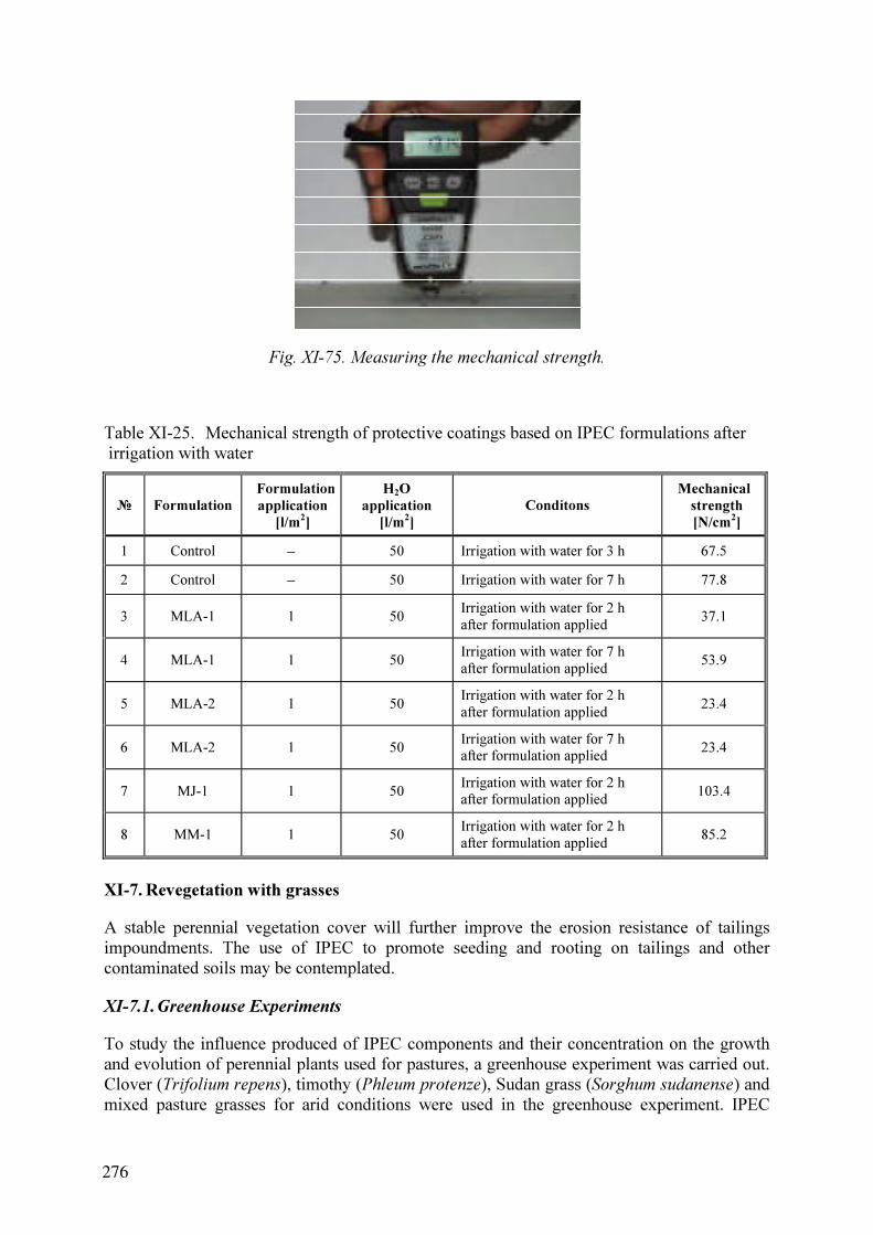
Fig. XI-75. Measuring the mechanical strength.
Table XI-25. Mechanical strength of protective coatings based on IPEC formulations after
irrigation with water
№ Formulation
Formulation
application
[l/m2
]
Н2O
application
[l/m2
]
Conditons
Mechanical
strength
[N/cm2
]
1 Control − 50 Irrigation with water for 3 h 67.5
2 Control − 50 Irrigation with water for 7 h 77.8
3 MLA-1 1 50
Irrigation with water for 2 h
after formulation applied
37.1
4 MLA-1 1 50
Irrigation with water for 7 h
after formulation applied
53.9
5 MLA-2 1 50
Irrigation with water for 2 h
after formulation applied
23.4
6 MLA-2 1 50
Irrigation with water for 7 h
after formulation applied
23.4
7 MJ-1 1 50
Irrigation with water for 2 h
after formulation applied
103.4
8 ММ-1 1 50
Irrigation with water for 2 h
after formulation applied
85.2
XI-7. Revegetation with grasses
A stable perennial vegetation cover will further improve the erosion resistance of tailings
impoundments. The use of IPEC to promote seeding and rooting on tailings and other
contaminated soils may be contemplated.
XI-7.1.Greenhouse Experiments
To study the influence produced of IPEC components and their concentration on the growth
and evolution of perennial plants used for pastures, a greenhouse experiment was carried out.
Clover (Trifolium repens), timothy (Phleum protenze), Sudan grass (Sorghum sudanense) and
mixed pasture grasses for arid conditions were used in the greenhouse experiment. IPEC
276
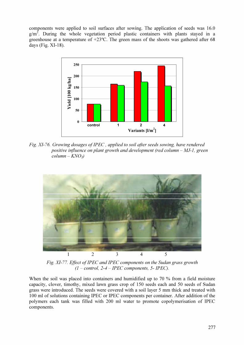
components were applied to soil surfaces after sowing. The application of seeds was 16.0
g/m2
. During the whole vegetation period plastic containers with plants stayed in a
greenhouse at a temperature of +23ºС. The green mass of the shoots was gathered after 68
days (Fig. XI-18).
0
50
100
150
200
250
Variants [l/m2
]
Yield
[100 k
g/h
a]
control 421
Fig. XI-76. Growing dosages of IPEC , applied to soil after seeds sowing, have rendered
positive influence on plant growth and development (red column – MJ-1, green
column – KNO3)
1 2 3 4 5
Fig. XI-77. Effect of IPEC and IPEC components on the Sudan grass growth
(1 – control, 2-4 – IPEC components, 5- IPEC).
When the soil was placed into containers and humidified up to 70 % from a field moisture
capacity, clover, timothy, mixed lawn grass crop of 150 seeds each and 50 seeds of Sudan
grass were introduced. The seeds were covered with a soil layer 5 mm thick and treated with
100 ml of solutions containing IPEC or IPEC components per container. After addition of the
polymers each tank was filled with 200 ml water to promote copolymerisation of IPEC
components.
277

XI-8. Results
The introduction of IPEC and KNO3 substantially influenced the development of the
vegetation. With the introduction of increased quantities of IPEC the biomass yield of clover
and weed increased from 0.8 g/m2
in the control to 2.45 g/m2
(this is a 306 % increase in
comparison to the control) for the highest dosage of IPEC, i.e. 4.0 l/m2.
(Fig. XI-18).
It was found that when polycations and polyanions were successively introduced in quantities
of 0.5 l/m2
of the mixture, the highest yield of plants was achieved in the experiment with
dosage of 157 % in relation to the control (Fig. XI-19).
XI-9. Recommendations for application of polymeric covers for uranium mill tailings
localisation
Results obtained during the project show that polymers developed on the bassis of IPECs
have a high efficiency as anti-erosion agents and may be recommended for application in
remediation. Application of 1.0-2.0 l/m2
of a dilute water-polymeric compositions with
polymer concentration only 2.0 wt% results a high stability of the upper layer of tailings.
The polymers may be used in the construction of multibarrier systems as efficient
composition for aiding vegetation. In this case joint application of polymers and seeding
grasses may be recommended following to tailings pile top cover design – erosion barrier (fig.
20). Clover (Trifolium repens), timothy (Phleum protenze), Sudan grass (Sorghum sudanense)
and mixed grasses adapted for local conditions showed good results. The addition of nutrients
may be needed for an improved vegetation process.
XI-10. SUMMARY AND CONCLUSIONS
(1) A review of the scientific and technical information on the remediation/stabilisation of
uranium mill tailings indicated that erosion of the surface covers could be a significant
problem. In this case the application of supplementary protection in the form of
polymeric structure formers may reduce wind or water induced destruction of a surface
cover.
(2) The erosion resistance of polymer-based protective coatings was assed under laboratory
conditions in a wind tunnel and a hydrodynamic test channel. Samples from a mill
tailings beach at Ulba Metallurgical Plant (Kazakhstan) and of simulated wastes from
the Zovtny Vody Plant (Ukraine) were tested. It was shown that the application of
polymeric structure formers significantly improves the wind and water erosion
resistance of unconsolidated materials powder materials. The erosion threshold of wind
erosion increased from 6,8 m/s for a dry untreated sample to 70.5 m/s for a sample
treated with MJ -1. The water erosion resistance of the mill tailings increased by a factor
of 1/5-2 (Keff> 11).
(3) As result of IPEC treatment the erosion resistance even for soils unprotected by a
vegetation layer increased in 1.4 times at a water flow velocity of 0.10 m/s and in 3.78
times at water flow velocity 0.67 m/s. The greatest effect estimated as increase of
erosion resistance on aggregates is noted in an interval of IPEC dosages of 1.5-2.5 l/m2
.
The increase of the of polymer dosage of up to 4.0 l/m2
is possible if necessary, thus
allowing to maintain high mechanical strength.
(4) It was observed that when polycation and polyanion were successively introduced at a
quantity 0,5 l/m2
of mixture the highest crop of plants was achieved in the experiment
with made up 157 % in relation to the control.
278
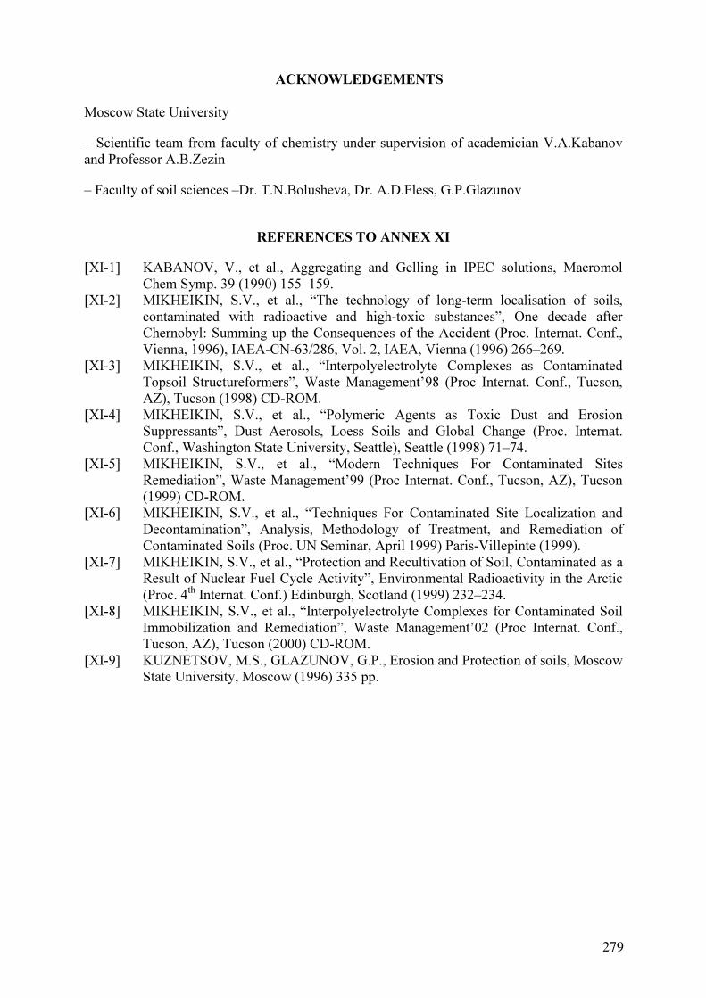
Moscow State University
– Scientific team from faculty of chemistry under supervision of academician V.A.Kabanov
and Professor A.B.Zezin
– Faculty of soil sciences –Dr. T.N.Bolusheva, Dr. A.D.Fless, G.P.Glazunov
REFERENCES TO ANNEX XI
[XI-1] KABANOV, V., et al., Aggregating and Gelling in IPEC solutions, Macromol
Chem Symp. 39 (1990) 155–159.
[XI-2] MIKHEIKIN, S.V., et al., “The technology of long-term localisation of soils,
contaminated with radioactive and high-toxic substances”, One decade after
Chernobyl: Summing up the Consequences of the Accident (Proc. Internat. Conf.,
Vienna, 1996), IAEA-CN-63/286, Vol. 2, IAEA, Vienna (1996) 266–269.
[XI-3] MIKHEIKIN, S.V., et al., “Interpolyelectrolyte Complexes as Contaminated
Topsoil Structureformers”, Waste Management’98 (Proc Internat. Conf., Tucson,
AZ), Tucson (1998) CD-ROM.
[XI-4] MIKHEIKIN, S.V., et al., “Polymeric Agents as Toxic Dust and Erosion
Suppressants”, Dust Aerosols, Loess Soils and Global Change (Proc. Internat.
Conf., Washington State University, Seattle), Seattle (1998) 71–74.
[XI-5] MIKHEIKIN, S.V., et al., “Modern Techniques For Contaminated Sites
Remediation”, Waste Management’99 (Proc Internat. Conf., Tucson, AZ), Tucson
(1999) CD-ROM.
[XI-6] MIKHEIKIN, S.V., et al., “Techniques For Contaminated Site Localization and
Decontamination”, Analysis, Methodology of Treatment, and Remediation of
Contaminated Soils (Proc. UN Seminar, April 1999) Paris-Villepinte (1999).
[XI-7] MIKHEIKIN, S.V., et al., “Protection and Recultivation of Soil, Contaminated as a
Result of Nuclear Fuel Cycle Activity”, Environmental Radioactivity in the Arctic
(Proc. 4th
Internat. Conf.) Edinburgh, Scotland (1999) 232–234.
[XI-8] MIKHEIKIN, S.V., et al., “Interpolyelectrolyte Complexes for Contaminated Soil
Immobilization and Remediation”, Waste Management’02 (Proc Internat. Conf.,
Tucson, AZ), Tucson (2000) CD-ROM.
[XI-9] KUZNETSOV, M.S., GLAZUNOV, G.P., Erosion and Protection of soils, Moscow
State University, Мoscow (1996) 335 pp.
ACKNOWLEDGEMENTS
279

ANNEX XII. UKRAINE
RESEARCH AND DEVELOPMENT OF MEASURES TO BE TAKEN FOR
LONG TERM STABILIZATION AND ISOLATION OF URANIUM MILL TAILINGS
G. Maslyakov
Ukrainian Research and Design Institute for Industrial Technology
XII-1. Abstract
This paper contains results of research on the environmental impact of uranium mill tailings
used for backfilling mined-out voids from uranium ore mining at Zhovty Vody. The general
objective of the research was a comparison of qualitative and quantitative characteristics of
the performance of using mill tailings as backfilling instead of the customary sand.
Specifically the backfill massif strengths, the radiation impact on the mine staff, possible
groundwater contamination with radionuclides from the backfill massif, and air and soil
contamination with dust and gas emissions from the mine and the backfill mixing plant were
investigated.
It was concluded that the use of tailings as a backfill material would be feasible, both from a
technical as well as an environmental impact point of view.
XII-2. Introduction
Production of U3O8 in the Ukraine involves uranium ore mining and milling processes and
results in various radioactive residues. The residues are stored in piles at the mine site (mining
waste) and in tailings ponds (milling wastes and tailings) located in natural geomorphological
depressions blocked by dams. Such residue management technology was acceptable 40 years
ago, but does not meet current radiation safety requirements.
In the Ukraine the more appropriate and preferable way of waste management is the disposal
in worked-out mine voids. This option significantly reduces negative impacts on the ambient
atmosphere and terrestrial environments, which is particularly important for the Ukraine with
its developed agriculture and fertile soils located over territories of prospective uranium
mining. However, practical use of this option is not yet permissible due to the non-availability
of relevant regulations and standards and a feasibility study.
Taking into account these problems, the only real option may be use of uranium mill tailings
as backfill material for the uranium ore mine [XII-1][XII-2].
Production of one tonne of uranium ore entails excavation of 0.37 m3
mine void to be
backfilled depending on the choosen mining technology. For backfilling, a special mixture is
used that consists of a binder, sand and water. After being placed into the mine it solidifies
into a hard and dense material [XII-3]. The materials balance for the current technology is
given in Figure XII.1
If the sand is replaced by mill tailings, it may be possible to utilize up to 35% of the total
waste quantity arising (Fig. XII.2). In this case, the waste disposal becomes part of the mining
technology, which in turn allows to undertake a feasibility study and to assess ecological
concequences of the facility for the surrounding area in accordance with procedures described
281

Binder Sand
Backfill mixture
preparation Storage
0.35 m3
Mine waste
0.6 t
Ore
2.7 t
Milling
Tailings 2.7 t
Storage
Products
Daylight
surface
Mixture
supply
Rock and ore mass
3.3 t
1 m3
mine space
Total storage volume 1.95 m3
Mining area
1 m3
mine space
Binder Sand
Backfill mixture
preparation Storage
0.35 m3
Mine waste
0.6 t
Ore
2.7 t
Milling
Tailings 2.7 t
Storage
Products
Daylight
surface
Mixture
supply
Rock and ore mass
3.3 t
1 m3
mine space
Total storage volume 1.95 m3
Mining area
1 m3
mine space
1 m3
mine space
Fig. XII-1. Materials quantities for the existing mine backfilling technology.
Binder
0.2 t
Backfill mixture
preparation Storage
0.35 m3
Mine waste
0.6 t
Ore
2.7 t
Milling
Tailings 2.7 t
Storage
0.75 m3
Products
Daylight
surface
Mixture
supply
Rock and ore mass
3.3 t
1 m3
mine space
Total storage volume 1.1 m3
1 m3
mine space
Tailings for backfilling
1.45 t
1.25 t
Mining area
Binder
0.2 t
Backfill mixture
preparation Storage
0.35 m3
Mine waste
0.6 t
Ore
2.7 t
Milling
Tailings 2.7 t
Storage
0.75 m3
Products
Daylight
surface
Mixture
supply
Rock and ore mass
3.3 t
1 m3
mine space
Total storage volume 1.1 m3
1 m3
mine space
1 m3
mine space
Tailings for backfilling
1.45 t
1.25 t
Mining area
Fig. XII-2. Materials quantities for using mill tailings in the mine backfill materials.
282

in relevant national regulations and standards [XII-1][XII-2][XII-4][XII-5]. The material
balance for such application is given in Figure XII.2.
The consequences of utilising uranium mill tailings as backfilling in mined-out voids are
discussed in the report.
XII-3. Objectives
The engineering decision to replace the sand by mill tailings in the backfill material provides
yet no complete isolation and long-term stabilization of uranium mining and milling wastes.
However, it improves disposal conditions and completely changes the picture of
environmental impact. While reducing the direct impact on surface, unfortunately at the same
time it worsens the radiation situation within the mine. In addition, the permeability of the
backfill materials and the leachability of chemicals and radionuclides from them may cause
contamination of groundwaters [XII-4][ XII-6][ XII-7].
A peculiarity of the existing ore reserves is that uranium deposits with a good prospect to be
developed are usually located in highly populated regions with a highly developed agriculture.
The general objective of the project was to comprehensively assess the ecological
consequences of a uranium mining technology utilising mill tailings as a backfill material.
The general objective of the research hence is a comparison of qualitative and quantitative
characteristics of the performance of customary backfill mixtures, in particular of mill tailings
instead of sand, during the mine operation.
The purpose of the research is to ensure that radionuclides released from the tailings will not
reach the environment in quantities and concentrations that may cause irreversible harm to
both nature and humans.
The complex ecological assessment is performed taking into account the requirements
established by appropriate Ukrainian standards [XII-1][XII-2].
XII-4. Research topics
Research topics and obtained results are given in Table XII-1.
Table XII-1. Research objectives and results.
Research topics Research results
Assurance of backfill massif strengths The backfill composition ensuring massif
strength has been determined
Radiation impact on the mine staff Mine air contamination has been predicted;
dose loading on the personnel has been
calculated
Groundwater contamination with
radionuclides from the backfill massif
Uranium and radium migration along
groundwater flow has been predicted
Air and soil contamination with dust and
gas emissions out of mine
Radon and dust volume activity variance in
the surface air has been predicted
283

XII-5. Assessment of the geotechnical properties of backfill mixtures
When a mineral deposit is developed by heading-and-stall method, the main parameter
determining the backfill massif strength is compression strength that is to be from 3 to 7 MPa
after six months of solidification. According to regular technology, back-fill mixtures are
made of sand with regulated grain composition. The tailings have completely different grain
composition; comparison is given in Table XII.2.
Table XII-2. Grain size distribution of sand to be used in backfill mixtures and uranium mill
tailings.
Percentage Grain size [mm]
sand mill tailings
5-2.5 0-20 −
2.5-1.25 5-25 −
1.25-0.63 15-25 –
0.63-0.315 35-10 −
0.315-0.16 35-20 6.4
0.16-0.1 10-0 8.7
0.1-0.074 − 9.8
0.074-0.04 − 15.3
< 0.04 − 59.8
Total 100 100
Table XII-3. Backfill mixture compositions that provides adequate compressive strength.
Amount [kg] per m3
Compressive No. of
composition Cement Slag Tailings
Crushed
rock
Water
strength
limit [MPa]
4 200 1450 − 400 3.1
6б 350 1380 − 400 4.9
6в 400 1360 − 400 7.0
16 200 − 1550 400 3.0
17 250 − 1500 400 4.6
18 300 − 1450 400 6.2
25 350 950 400 400 4.4
26 400 950 350 400 5.2
38 400 950 350 380 4.5
44 − 600 950 250 400 3.0
Different grain size distributions require the evaluating the geomechanical performance of the
massif after its having solidified. The procedure for the determination of compressive strength
used for controls at Ukrainian mines is based on testing of backfill material standard samples
after curing them for 7 days, 29 days, 3 months and 6 months respectively. The composition
of the backfill mixture was selected by experiment, considering different ratios of binder and
mill tailings. In total 49 samples were prepared and tested. The test results allowed to select a
284

backfill mixture composition that is close to the standard values of compressive strength. A
reasonable performance is achieved when Portland cement is used as a binding agent at a rate
of about 200 to 400 kg per m3
of the mixture.
The backfill composition is selected on the basis of experiments with different ratios of
binding agents and tailings as a filling agent.
XII-6. Radiation impact on staff
Radiation conditions in the mine workings have been predicted. Mine air contamination at 40
workplaces was considered together with the air removed from the mine by the ventilation
system by modelling the distribution of contaminated air along the mine workings. The model
was developed on the basis of the assumption that collector ventilation system would be
applied to ventilate the mine workings, where the contaminated air is collected into a special
vent header arranged near the main level. The parameters of the model are given in Table
XII.4.
Table XII-4. Main parameters of the Rn exposure model.
Parameters Value Unit
1. Number of mine workings (equivalent to calculational branches) in
model
410 no.
2. Number of units in model (branch joints) 195 no.
3. Radon flux into mine sections:
being worked
backfilled with solidified material
59.52
67.3
kBq·s-1
kBq·s-1
4. Radon flux from water exuded from solidified backfill materials in the
mine
0.233 kBq·s-1
5. Pressure in mine ventilation network 4507 Pa
6. Air consumption of the mine 476 m3
·s-1
7. Number of work places considered:
mine roadheading
bore drilling in blocks in operation
ore loading in car- truck
ore extraction from mine block
mine void abandoning and backfilling
2
12
12
12
2
no.
no.
no.
no.
no.
Table XII-5. Modelled mine air contamination.
Weighted-average concentration in air at working
places [Bq/m3
] for each use of backfill material
sand-and-slag mixture
(SSM)
cement-and-tailings
mixture (CTM)
Mining activities
Radon Rn progeny Radon Rn progeny
1. Mine roadheading 408 48.84 408 50
2. Drilling in operational blocks 2119 559.4 2132 567
3. Ore loading in car truck 2104 550.6 2104 550.6
4. Ore extraction from mine block 1624 385.17 1629 285.17
5. Mine void abandoning and backfilling
— mounting and maintenance of backfilling
pipe-line
3607 1670 4475 2006
— backfill materials supply 2069 520 2069 520
285

Mine air contamination parameters (see Table XII.5) were used to calculate the dose to staff
at the main workplaces in the mine, both when conventional backfill technology is applied
and when mill tailings are utilised for backfilling.
The inhalation component of effective dose for the staff depending on the workplaces location
(Table XII.6) 1.03-1.2 times increases when tailings used for mined-out space backfilling.
Table XII-6. Calculated mining personnel exposures.
Personnel exposure [mSv/year]
Mining activities sand-and-
slag (SSM)
cement-and-
tailings (CTM)
Ratio
SSM/CTM
1. Mine roadheading 0.64 0.66 1.03
2. Drilling in operational blocks 7.4 7.5 1.01
3. Ore loading in car truck 7.28 7.2 1.0
4. Ore extraction from mine block 5.1 5.1 1.0
5. Mine void abandoning and
backfilling
mounting and maintenance
of backfilling pipe-line
9.64 11.55 1.2
backfill material supply 6.88 6.88 1.0
XII-7. Contamination of groundwaters with radionuclides from the backfill massif
After the deposits are exhausted, the mine is closed, and the groundwater table has recovered
to its pre-mining level, the backfill massif is expected to become a source of uranium series
radionuclides. Release to the groundwater is followed by migration along the water flow paths
to the areas of natural discharge.
The list of groundwater contaminants to be investigated were determined according to the
radiochemistry of the backfill material. This list includes 238
U and 226
Ra, for which the
concentrations in the backfill material are 1,722 Bq·kg-1
and 5,922 Bq·kg-1
respectively in
accordance with previous research and estimation results.
The radionuclides will migrate in an aquifer that largely consists of fractured granites. U and
Ra migration distances depend on the porewater chemistry of the granites and their sorption
properties. The source term depends on the chemistry of the backfill material and the water
flux through the backfill. The latter in turn depends inter alia on the permeability of the
backfill material.
286
Predictions of contaminant transport were made using the “Ground Water Flow Simulation
(GWFS)” software produced by Geosoft-Eastlink Company (Russia/Sweden) and the FLOW
utility designed to model migration processes in a vertical cross-section. The geometry of the
hydrogeological model domain is determined by the distribution of the backfill material in the
geological section and also by the groundwater flow patterns. A (hydro)geological cross-
section is shown in Figure XII.3.

Loess loams
Sands
Residual soil crust including wood
and stone chips, and kaolin clay
Fractured granites
Backfill massif
Groundwater table
200
100
0
-100
-200
-300
-400
-500
0 100 200 300
Loess loamsLoess loams
SandsSands
Residual soil crust including wood
and stone chips, and kaolin clay
Fractured granitesFractured granites
Backfill massifBackfill massif
Groundwater tableGroundwater table
200
100
0
-100
-200
-300
-400
-500
0 100 200 300
Fig. XII-3. Geological cross-section of the mine site.
Two cases for the state of the backfill material were considered for the prediction of the long-
term contaminant behaviour:
backfill material has the same permeability as the enclosing rock, i.e. permeability
coefficient is 0.06 m·d-1
;
the backfill material has degraded and its permeability coefficient amounts now to
1.4 m·d-1
.
The permissible and average concentrations of the radionuclides in the vicinity of ore deposit
are listed in Table XII-7.
Table XII-7. Groundwater contamination criteria.
Permissible concentrations
according to NRBU-97
Average concentrations around
the deposit Radionuclide
Bq·l-1
mg·l-1
Bq·l-1
mg·l-1
238
U 10 0.4 0.55 0.02
226
Ra 1 0.05
The prediction was made for time points corresponding to a 100 and 1000 year period after
the mine has stopped to be worked, the mine voids have been backfilled, and the
hydrogeological regime of the groundwater has been reconstituted.
After 100 years, the boundary of permissible uranium concentration (see Table XII-7) is
predicted to occur at distance of 129 m from the backfill massif for a maximum permeability
coefficient 1.04 m·d-1
, while the average concentration (0.02 mg/l) will be observed at a
distance of 755 m (Fig. XII-4).
In 1000 years the boundary of average uranium concentrations, will move northwards and be
out of the model domain (Fig. XII-5).
287

After 100 years the boundary of average radium concentration will be at 663 m distance from
the backfill massif for a permeability coefficient of 1.04 m/day (Fig. XII-6).
After 1000 years the boundary will have moved back due to radioactive decay and would be
observed at 465 m distance (Fig. XII-7).
Fig. XII-4. Model outputs for uranium transport by groundwater in the aquifer in prediction
for 100-year time period and permeability coefficient 1.04 m·d-1
.
Fig. XII-5. Model outputs for uranium transport by groundwater in the aquifer in prediction
for 1000-year time period and permeability coefficient 1.04 m·d-1
.
288

Fig. XII-6. Model outputs for radium transport by groundwater in the aquifer in prediction
for 100-year time period and permeability coefficient 1.04 m·d-1
.
Fig. XII-7. Model outputs for radium transport by groundwater in the aquifer in prediction
for 1000-year time period and permeability coefficient 1.04 m·d-1
.
XII-8. Air and soil contamination
Emissions are released into the ambient air from the mine ventilation exhausts, by which
contaminated mine air is brought to the surface from underground workings and from the
ventilation systems of the backfill mixing plants. Radon is emitted from the backfill massif,
while the backfill mixing plants emit radon and dust.
The mine air is contaminated as a result of radon emanation from the backfill massif prepared
with use of uranium mill tailings. Generation of dust is due to the tailings being handled,
289

transported, and mixed. Atmospheric emission point geometric parameters and measured
emission values are presented in Table XII-8.
Table XII-8. Characteristics of atmospheric emission points.
Emission point parameters
Operating
time
Emissio
n speed
Geometric
parameters
Radon emission Dust emission Emission point
[h·y-1
] [m·s-1
] [m] [kBq·s-1
] [kBq·y-1
] [g·s-1
] [t·y-1
]
Mine ventilation
exhaust 6094 10.7
Ø= 5.6
H=20
1892.9 4.15·1010
–
Backfill mixing plant
ventilation systems:
- dewatering
plant8160 10.0
Ø= 0.8
H=240.23 6.76·10
6
0.031 0.687
- storage
area,
mixing area
6094
6.0
16.0
Ø= 1.0
H=20
338.76 5.267·109
0.06 1.764
0
0
10000
S
S-W
S-E
EW
N-W
N-E
N
Mine Ventilation Exhaust
Backfill mixing plant
100005000
5000
I
I
Fig. XII-8. Model grid, emission point locations, and average wind direction distribution.
The impact of atmospheric emissions is evaluated on the basis of surface air concentrations.
Modelling has been carried out for an area of 10,000 m ×10,000 m, with a grid space of
250 m. The emission point locations are presented in Fig. XII-8.
290

Radon and dust volume activities in the surface air (on section I-I) resulting from calculations
for emissions from the mine ventilation exhaust and the backfill mixing plant under annual
average wind speed conditions (cf. Fig. XII-8) and the ‘unfavourable’ weather conditions
respectively are given in Fig. XII-9.
0
0.2
0.4
0.6
0.8
1
1.2
1.4
1.6
6500 7500 8500 9500
Distance [m]
Activity, B
q·m
-3
Rn-222 at annual average wind
speed
Rn-222 at 'unfavourable' weather
conditions
Mine Ventilation Exhaust
Fig. XII-9. Volume activity variation for radon emitted from the backfill massif through the
mine ventilation exhaust.
0
2
4
6
8
10
12
14
16
18
20
5000 6000 7000 8000 9000 10000
Distance [m]
Activ
ity
, B
q m
-3
Rn-222 at average
annual wind speed
Rn-222 at 'unfourable'
weather conditions
Backfill mixing plant
Fig. XII-10. Volume activity variation for radon emanating from the backfill mixing plant.
291

0
5
10
15
20
25
5000 6000 7000 8000 9000 10000
Distance [m]
Activity, B
q m
-3
Rn-222 at average annual wind
speed
Rn-222 at ‘unfavourable’ weather
conditions
Backfill mixing plant
Mine ventilation exhaust
Fig. XII-11. Volume activity variation for radon in the surrounding air due to the combined
effect of mine ventilation and backfill mixing plant exhaust.
0
0.001
0.002
0.003
0.004
0.005
5000 6000 7000 8000 9000 10000
Distance [m]
Co
ncen
tra
tio
n, m
g m
-3
Dust at average annual
wind speed
Dust at ‘unfavourable’
weather conditions
Backfill mixing plant
Mine ventilation exhaust
Fig. XII-12. Dust dispersion from the backfill mixing plant.
Maximum radon activities over the site are calculated as 11.6 Bq·m-3
for the average annual
wind speed and as 22.5 Bq·m-3
for the ‘unfavourable’ weather conditions.
Average measured concentrations of the basic radionuclides in the dust are as follows: 2,516
Bq·kg-1
for uranium; 2,789 Bq·kg-1
for 226
Ra; and 9,768 Bq·kg-1
for 230
Th.
The distribution of volume activities for radionuclides in the dust emitted to the surface air
from the backfill mixing plant for the average annual wind speed and the ‘unfavourable’
292
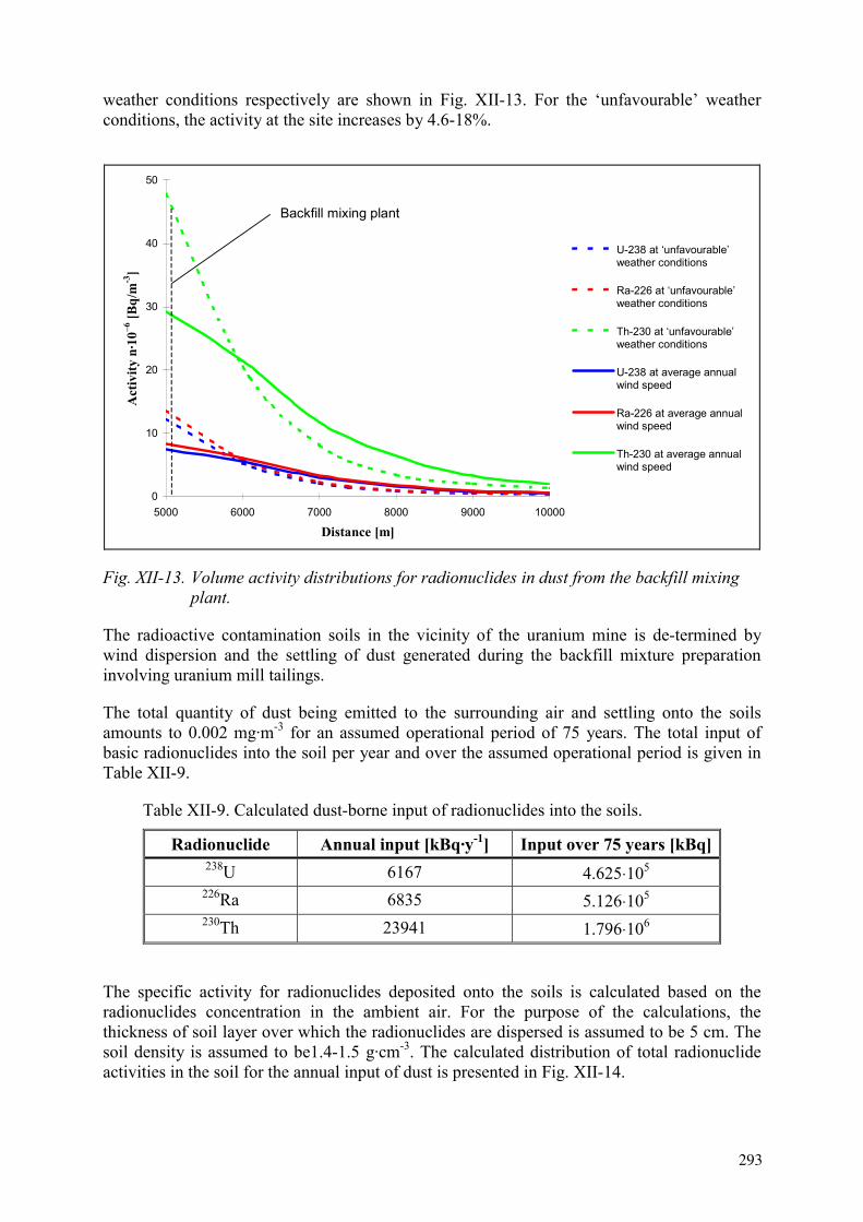
weather conditions respectively are shown in Fig. XII-13. For the ‘unfavourable’ weather conditions, the activity at the site increases by 4.6-18%.
0
10
20
30
40
50
5000 6000 7000 8000 9000 10000
Distance [m]
Act
ivity
n·1
0–6 [B
q/m
-3]
U-238 at ‘unfavourable’weather conditions
Ra-226 at ‘unfavourable’weather conditions
Th-230 at ‘unfavourable’weather conditions
U-238 at average annualwind speed
Ra-226 at average annualwind speed
Th-230 at average annualwind speed
Backfill mixing plant
Fig. XII-13. Volume activity distributions for radionuclides in dust from the backfill mixing plant.
The radioactive contamination soils in the vicinity of the uranium mine is de-termined by wind dispersion and the settling of dust generated during the backfill mixture preparation involving uranium mill tailings.
The total quantity of dust being emitted to the surrounding air and settling onto the soils amounts to 0.002 mg·m-3 for an assumed operational period of 75 years. The total input of basic radionuclides into the soil per year and over the assumed operational period is given in Table XII-9.
Table XII-9. Calculated dust-borne input of radionuclides into the soils.
Radionuclide Annual input [kBq·y-1] Input over 75 years [kBq] 238U 6167 4.625⋅105
226Ra 6835 5.126⋅105
230Th 23941 1.796⋅106
The specific activity for radionuclides deposited onto the soils is calculated based on the radionuclides concentration in the ambient air. For the purpose of the calculations, the thickness of soil layer over which the radionuclides are dispersed is assumed to be 5 cm. The soil density is assumed to be1.4-1.5 g·cm-3. The calculated distribution of total radionuclide activities in the soil for the annual input of dust is presented in Fig. XII-14.
293

0 10000
10000
0
1
2 23
3
45
67
8
9 Backfill mixing plant
Iso-line Specific activity [Bq/kg]
238U 226Ra 230Th 1 0.0043 0.0047 0.017 2 0.0032 0.004 0.014 3 0.0028 0.003 0.012 4 0.0023 0.0025 0.00895 0.0018 0.002 0.00686 0.0013 0.0014 0.00517 0.00077 0.00084 0.003 8 0.00033 0.0004 0.00139 0.00011 0.00012 0.00043
Fig. XI-14. Calculated radionuclide specific activity distribution in the soil as a result of annual sedimentation of dust from the uranium mill tailings.
Table XII-10. Background activity concentrations of radionuclides in the soil.
Sample Activity concentration [Bq·kg-1]No. 238U 226Ra 232Th 40K
1 50 40 80 200
2 130 60 70 400
3 60 40 80 300
4 50 40 60 400
Average 72.5 45 72.5 325
Table XII-11. Calculated dust-borne contamination of soils at the border of the industrial zone.
Radionuclide Dust-borne activity concentration [Bq·kg-1]
Natural background [Bq·kg-1]
Dust-borne contribution [%]
238U 0.165 72.5 0.22 226Ra 0.183 45 0.4 230Th 0.64 - -
294
The calculated mining derived activity concentrations are compared with the background
activity concentrations of natural radionuclides in the soil. Background concentrations have
been found by an experimental approach using four samples taken at places unaffected by
mines (Table XII-10).
Maximum specific activities of the radionuclides in the soils are observed within the
industrial zone of the object. Table XII-11 shows the expected radionuclide activity
concentrations at the border of the industrial zone resulting from an input into the soil over an
operational period of 75 years.
XII-9. Conclusions
The use of mill tailings as a component in the backfill mix for a uranium mine results in
changes in the radiation impact on the staff and the population living in the surrounding area
that is affected by dust and gas emission from the mine.
The additional contribution to the ambient air contamination in the vicinity of the uranium ore
mine is estimated to be 10-18%. However. the radiation impact does not exceed the limiting
values established by the state regulations.
The contamination of groundwaters due to the leaching and migration of radionuclides from
the backfill massif is estimated to be limited to the natural halo of radionuclides in the host
rock around the uranium deposit.
The soil contamination from the preparation of backfilling mixtures using uranium mill
tailings does not significantly increase in comparison with the impact from conventional
backfilling technology.
REFERENCES TO ANNEX XII
[XII-1] DBN A.2.2.1.-95, “Structure and content of matters for assessment of
environmental impact...”
[XII-2] NRBU-97, “Radiation Safety Standard of Ukraine”.
[XII-3] REGULATORY MATERIAL, “Temporary manual for determination of outcrop
spans and standard strength of solidifying backfill materials for uranium mine of
Ukraine, RM 95.8-684-82 (1982) (in Russian).
[XII-4] SPORO-85, “Sanitary rules of radioactive waste management”, (1996) (in Russian).
[XII-5] OST 95 592-86, “Radioactive waste. General requirements to radionuclide content
and activity measuring methods”, (1987).
295

ANNEX XIII. USA
RESEARCH AND DEVELOPMENT OF MEASURES TO BE TAKEN FOR LONG
TERM STABILIZATION AND ISOLATION OF URANIUM MILL TAILINGS
S.R. Metzler
US DOE, Grand Junction Office
XIII-1.Abstract
The U.S. Department of Energy has taken a holistic approach to the remediation of uranium
mill tailings and contaminated groundwater at the Title I sites designated in the Uranium Mill
Tailings Radiation Control Act. This approach is suggested as guidance for the
characterization and remediation of other sites with contamination, depending on site-specific
or country-specific conditions.
This paper describes the process using certain specific examples.
XIII-2.Introduction
XIII-2.1. Initial scoping
The first step in the environmental restoration of a uranium mill tailings site (Fig. XIII-1) is to
collect all available existing information to become familiar with the site. The primary goals
of this initial scoping are to determine whether any risks and hazards are present that require
immediate attention and to define the project scope (problem definition). The results of this
scoping will be a summary report describing the physical features of the site, a summary of
historical information, and an initial assessment of risks and immediate corrective measures.
Fig. XIII-1. During the early years of processing uranium ore in the United
States, liquid waste was piped to ponds where the liquid component
evaporated, leaving fine sandlike tailings.
297

XIII-2.2. Define problem and potential risks
Problem definition includes determining the physical parameters of the site, examining
historical records, and identifying potential risks. Physical parameters include the major
physiographic features (man-made and natural), climate, site ownership and access, and
current and former land use. Historical photographs, maps, and reports are useful in
identifying physiologic features, especially maps for utilities (e.g., electricity, gas, and water)
and as-built drawings. Interviews with current and former employees are helpful in
identifying former practices that may have contributed to environmental releases. Site records
should include procedures, environmental reporting requirements, process information,
chemical usage, waste disposal, permits, and maintenance activities. A literature search may
provide additional information, such as public documents, process information, and technical
studies.
An inspection of the site should include a walk-through of all on-site facilities. Specific items
to look for associated with the milling process include raffinate ponds, tailings ponds,
processing facilities, evidence of underground tanks and piping, utilities, landfills, and waste
pits. In addition, potential exposure pathways should be investigated, such as windblown
contamination, surface water bodies, wells, and wetlands (Fig. XIII-2).
Fig. XIII-2. Environmentally dispersed radionuclides and wastes from uranium mill
tailings use various pathways to affect living organisms, soil, surface
water, and groundwater.
Information gathered during the review of historical information and the site inspection
should be compiled in a list of contaminants of potential concern with potential pathways and
receptors. Contaminants of potential concern may be radioactive constituents of the tailings
and leftover ore; chemicals used in the processing, such as acids or caustics; and substances
used in the operations, such as fuels and solvents. This initial phase of the risk assessment
determines whether immediate corrective actions should be implemented.
All the information gathered in the initial scoping should be documented in a summary report
that includes the collected data, an analysis of the data, immediate corrective actions as
298

warranted, and a summary of data gaps needed to complete the characterization of the site.
The data analysis should include a site conceptual model and the results of the initial risk
assessment. An evaluation of the need for an emergency or interim action should be made
based on the initial evaluation of types of contamination and exposure. An emergency action
may be to remove people from an area or to provide an alternate drinking water source.
XIII-2.3. Initiate emergency and interim actions
If an emergency or interim action was deemed necessary in the initial scoping phase, the
action should be completed as soon as possible. A minimum amount of review and public
input should be done so the action can be initiated as soon as possible.
XIII-3.Planning
A clear definition of short- and long-term objectives and goals is necessary for efficiency and
focus of the project. Objectives may include meeting regulatory standards or reducing risk to
acceptable levels. Goals may be established to complete specific phases of the work within a
certain time period or budget.
Stakeholders include owners, regulatory agencies, nearby residents, state and local
governments, and other interested parties. Stakeholders are identified early in the project to
establish communication (Fig. XIII-3).
Fig. XIII-3. Communication with stakeholders is an integral component of remedial action.
Applicable regulations are identified to determine cleanup standards and goals. The cleanup
standards and goals will guide the level of characterization to be performed and will narrow
the list of potential remedies. Focusing on potential remedies early in the process helps to
move the project toward the end goal of site cleanup. It also helps limit data collection to that
which is necessary to implement the potential remedies.
Management plans are prepared to ensure consistency within the various project tasks, to gain
consensus from the various stakeholders, to document the progress of the project. The Project
Plan describes the goals and objectives, scope, schedule, budget, project organization, roles
299

and responsibilities, procedures, and milestones. The Public Involvement Plan describes
actions to encourage stakeholder involvement and understanding to support the decision-
making process. The Quality Assurance Plan describes the quality requirements including
data collection, laboratory analysis, and technical calculations. The Health and Safety Plan
describes the health and safety concerns of the project, roles and responsibilities, emergency
procedures, job safety analysis, and training requirements. The Analytical Laboratory
Procedures Plan describes the analytical procedures to be used, including quality assurance
requirements. A Procurement Plan describes the procurement processes and major subcontract
requirements. A Records Management Plan describes the control, retention, index, filing, and
storage requirements for project records (Fig. XIII-4). A Database Management Plan describes
how the data will be managed, including how it will be stored, what types of data will be
stored, who will have read/write access, data formats, and electronic transfers.
Fig. XIII-4. Records Management Plans provide the requirements for project records,
both historical records and records generated during the cleanup process.
Technical plans are prepared to document the evaluation of existing data, to define what
additional tasks need to be accomplished, and to provide a means of gaining consensus among
stakeholders on future work. Technical plans generally fall into two categories: work plans
and procedures.
Work Plans are prepared for performing fieldwork, such as installation of monitor wells, pilot
tests, and performance monitoring. Work Plans will typically include an evaluation of existing
data, a discussion of data deficiencies, data quality objectives, and procedures. Data collection
procedures are included to ensure that methods are understood and approved by stakeholders.
Sampling and Analysis Plans contain procedures for all types of media sampling and analysis
and for location and frequency of sampling. Analytical methods include field methods as well
as laboratory methods.
XIII-4.Site characterization
XIII-4.1. Field investigations
Field investigations include performing land surveys and develop base maps, including
geographical, topographical, and man-made features. Accurate coordinates and elevations
need to be established for existing wells, surface water features, geologic contacts, historical
source areas, etc.
300

Collection of field data consists of conducting field sampling (Fig. XIII-5a) in accordance
with Work Plans. Schedule activities to maximize resources, to enhance data quality, and to
minimize costs. A phased approach should be used to sequence the activities to achieve a
(a)
(b)
Fig. XIII-5. (a) Collection of soil samples is necessary to determine the extent of
contamination and define the types of contaminants; (b)
Fig. XIII-6. A field laboratory offers quick turnaround times for some types of sample
analyses and allows investigators to determine extent of sample collection.
301

more logical sampling approach; for example, start with nonintrusive methods to obtain a
more complete and comprehensive understanding of the problem before more direct
characterization methods are employed. Integrate existing information with new data to revise
the site conceptual model and to refine data collection needs concurrent with or before
proceeding to the next activity. Lead time for procurement activities, resource availability,
remoteness of site, weather conditions, and other issues should be considered. Work readiness
reviews can be used to minimize the possibility of delays and problems because of incomplete
planning and preparation.
Coordinate field sampling with the analytical laboratory(s) with respect to holding times,
analyte list, sample matrix, preservatives, and shipping and transportation regulations for
hazardous material. Consider the lead time for laboratory audits and qualifications,
procurement, etc. Focus the investigation as much as possible on using field laboratories and
to reduce the volume of samples submitted to fixed-base laboratories(Fig. XIII-6).
XIII-4.2. Geographical information system database development
Location, sample, and base map information for geographical information system (GIS)
database development involves establishing a database structure with location information
such as wells, boreholes, surface (Fig. XIII-5b). Sample information may include surface
water, groundwater, soil, sediment, tailings, fauna, biota, analytical results, inorganic, organic,
radiologic, etc. Base map features include roads, fences, buildings, ponds, lakes, streams,
rivers, boundaries, geological, ecological, etc.
XIII-4.3. Data evaluation and reports
XIII-3.3.1 Determine nature and extent of contamination
Prepare maps, diagrams, and figures to assist in the evaluation of the geological, hydrological,
geochemical, and ecological data. Geologic evaluation considers regional and local geology,
bedrock structure and topography, and unconsolidated units. Hydrologic characterization
evaluates surface hydrology, groundwater hydrology, and aquifer interaction with surface
features. Physical features, coordinate survey information, geologic, and hydrologic data are
input into a groundwater flow model to develop the hydrostratigraphic model. Geochemical
characterization delineates the area where contamination exists, documents the individual
chemical constituents that contribute to the contamination, and evaluates the fate and transport
of the site-related contaminants. This evaluation includes an analysis of natural background,
source areas and contaminants, water quality, soil, and sediments. The geochemical processes
need to be identified for each contaminant that cause contaminant retardation, such as
adsorption, absorption, precipitation, diffusion into immobile porosity, transfer to vapor
phases, etc.
The geochemical characterization can be combined with the groundwater flow model to
predict the concentrations and distributions of contaminants. Ecological evaluations are
performed to assess ecological risks associated with site-related contaminants and to assist in
developing the site conceptual model. Vegetation at the site and surrounding areas should be
mapped to support the water balance model. Vegetation can influence both recharge and
discharge from groundwater sources, depending on the health of the plant communities, soil
properties, and depth to water.
302

XIII-3.3.2 Finalize site conceptual model
Integration of the site characterization data provides the most current understanding of the
extent and magnitude of contamination (Fig. XIII-7), exposure pathways, and risks to public
health and the environment. This integrated model of the site can be used to support the
proposed groundwater remediation objectives.
Fig. XIII-7. Selected geochemical and hydrological information is displayed in
a three-dimensional model.
XIII-4.3.1. Prepare environmental and human health risk assessment
The environmental and human health risk assessment will determine ecological and human
receptors for each potential exposure pathway, identify contaminants for each pathway, and
compare contaminant concentrations in media to appropriate benchmarks and to toxicity data
to estimate risk.
XIII-5.Remedial alternatives
Finalizing the objectives includes determining a final list of applicable rules and regulations
and a detailed evaluation of the risks. The applicable rules and regulations and the risks will
determine the cleanup levels, time required for cleanup, and a list of contaminants. The
holistic approach develops surface remediation objectives that consider the effects of surface
and vadose zone contamination on groundwater contamination.
Surface remediation objectives should address specific regulations that are in effect, the risks
from exposure to radon and radiation from the tailings, and vadose zone contamination that
may affect groundwater contamination. In the United States, regulations dictate acceptable
levels for radon and radioactive emissions, allowable levels for radioactive contaminants left
in the soil, and design standards for construction of disposal cells.
Groundwater objectives should address the allowable concentrations of contaminants in the
groundwater. The allowable concentrations of contaminants should be based on the current
303

and potential uses of the groundwater and the desired groundwater quality for those uses. The
objectives should also address the cleanup time to restore the groundwater to the desired
groundwater quality. Clean up time may be dictated by a regulation or be based on a policy
decision.
XIII-5.1. Development and evaluation of surface remediation alternatives
Surface remediation alternatives should be developed that address the remediation objectives
for both the surface and the groundwater. Groundwater cleanup standards may determine the
amount of tailings and contaminated soil to remove. If regulations dictate that a disposal cell
be built and the standards for design, alternatives may only consider whether to leave the
tailings in place or to relocate the tailings and how much contaminated material to remove
(Fig. XIII-8). Alternatives also may consider institutional controls, such as deed restrictions,
as a way to limit exposure or a variation in design standards for a disposal cell. In the United
States, a no action alternative (i.e., no remediation) is developed for comparison purposes.
Fig. XIII-8. Windblown tailings increase both the areal extent of contamination
and the area that requires characterization.
Surface remediation alternatives should be evaluated for effectiveness, implementability, and
cost. Effectiveness evaluates how well the alternative meets the objectives. Implementability
evaluates whether it is technically feasible to construct and operate the alternative and
whether there are administrative issues that may affect construction and operation. Cost may
evaluate the overall cost of the alternative or just the initial construction cost. The overall cost
includes the construction cost, operation and maintenance cost, and the long-term monitoring
cost. If the alternative uses a new technology or technique, treatability or pilot tests may be
needed to verify performance.
The selected alternative should provide the best balance of effectiveness, implementability,
and cost, depending on the importance assigned to each evaluation criteria. For example, the
alternative that provides the highest measure of effectiveness will probably have the highest
initial cost.
A report should be prepared that documents the remediation alternative that was selected and
the rationale for that selection. The report should be made available for all interested parties to
review.
304
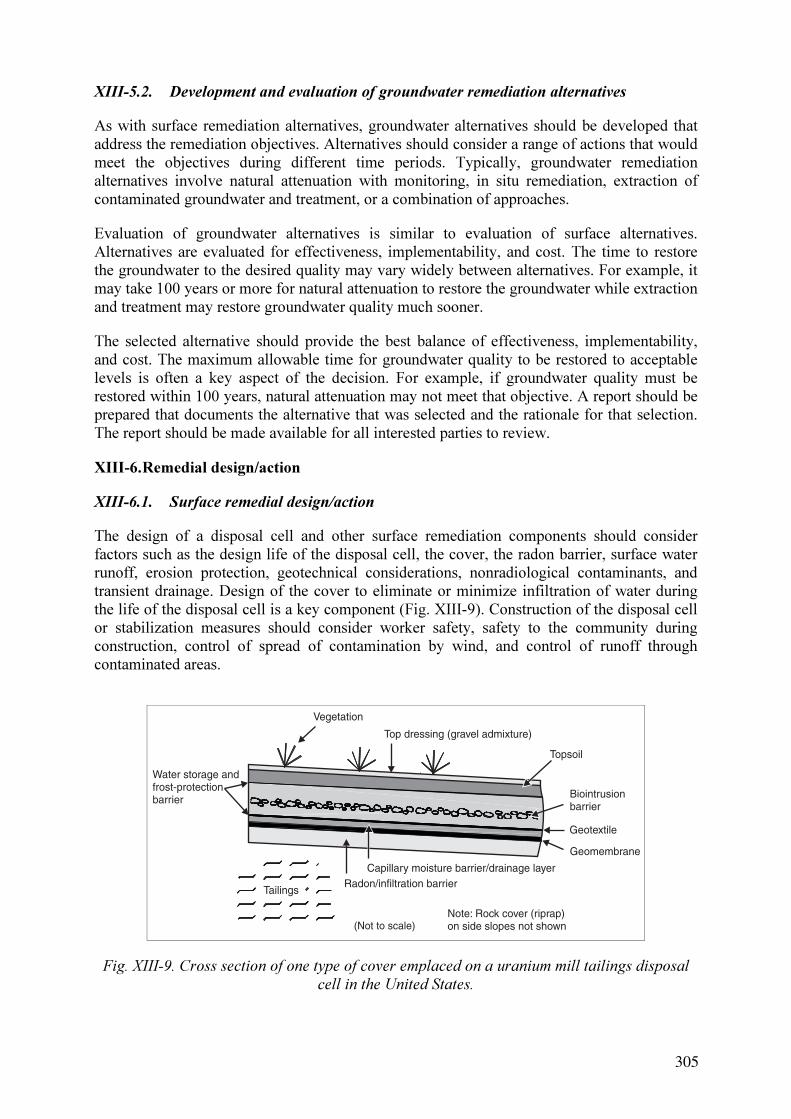
XIII-5.2. Development and evaluation of groundwater remediation alternatives
As with surface remediation alternatives, groundwater alternatives should be developed that
address the remediation objectives. Alternatives should consider a range of actions that would
meet the objectives during different time periods. Typically, groundwater remediation
alternatives involve natural attenuation with monitoring, in situ remediation, extraction of
contaminated groundwater and treatment, or a combination of approaches.
Evaluation of groundwater alternatives is similar to evaluation of surface alternatives.
Alternatives are evaluated for effectiveness, implementability, and cost. The time to restore
the groundwater to the desired quality may vary widely between alternatives. For example, it
may take 100 years or more for natural attenuation to restore the groundwater while extraction
and treatment may restore groundwater quality much sooner.
The selected alternative should provide the best balance of effectiveness, implementability,
and cost. The maximum allowable time for groundwater quality to be restored to acceptable
levels is often a key aspect of the decision. For example, if groundwater quality must be
restored within 100 years, natural attenuation may not meet that objective. A report should be
prepared that documents the alternative that was selected and the rationale for that selection.
The report should be made available for all interested parties to review.
XIII-6.Remedial design/action
XIII-6.1. Surface remedial design/action
The design of a disposal cell and other surface remediation components should consider
factors such as the design life of the disposal cell, the cover, the radon barrier, surface water
runoff, erosion protection, geotechnical considerations, nonradiological contaminants, and
transient drainage. Design of the cover to eliminate or minimize infiltration of water during
the life of the disposal cell is a key component (Fig. XIII-9). Construction of the disposal cell
or stabilization measures should consider worker safety, safety to the community during
construction, control of spread of contamination by wind, and control of runoff through
contaminated areas.
Fig. XIII-9. Cross section of one type of cover emplaced on a uranium mill tailings disposal
cell in the United States.
305

A disposal cell designed to last for several hundred years to 1,000 years requires periodic
monitoring and maintenance. Monitoring involves obtaining samples from groundwater wells
to determine whether the cover is allowing water to infiltrate and site visits to inspect the
erosion control measures and the integrity of the cell.
XIII-6.2. Groundwater remedial design/action
Depending on the selected remedy, the groundwater remediation design will vary
considerably. For natural attenuation, design activities will involve establishing a monitoring
plan and designing additional monitor wells. For an extraction and treatment remedy,
activities will involve designing the extraction wells, determining placement of the wells,
designing injection wells or infiltration trenches (if used), and designing the treatment system.
The remedial action phase may be limited to installing additional monitor wells required to
monitor natural attenuation (Fig. XIII-10). If the selected remedy is extraction and treatment,
remedial action will involve installation of the extraction and injection wells and construction
of the treatment system.
Fig. XIII-10. A drill rig is positioned prior to drilling a monitor well at a remediation site.
All groundwater remediations require a significant amount of monitoring constituents and
their concentrations in the groundwater. For natural attenuation and in situ remediations, post-
construction activities are limited primarily to monitoring. For extraction and treatment
remedies, operation of the extraction well field and the treatment system are the major
activities.
XIII-7.Performance evaluation
Monitoring activities are designed to determine the progress of the remediation approach in
meeting the goals and standards established for the site. Physical boundaries are monitored to
ensure integrity of fences, changes in land use, etc. Sampling and analysis is performed to
306

document increases and decreases in contaminant concentrations during remedial action, to
track progress of natural attenuation sites, and to provide early warning of plume migration
into uncontaminated areas. An institutional control program should be developed to prevent
future use of potentially harmful contaminated groundwater. Compliance of any property
restrictions needs to be monitored on use of drinking water, livestock watering, irrigation of
edible vegetation, and uses of ponds for ornamental or landscaping purposes.
Fig. XIII-11. This mill, located near Grand Junction, Colorado, processed uranium ore from
1951 until 1970; three tailings ponds are visible in the foreground.
Fig. XIII-12. Plans for a portion of the remediated Grand Junction, Colorado, millsite,
adjacent to the Colorado River, include development of a riverfront park and
trail system. Only one building (in circle) remains after cleanup of the site.
Verification involves continued monitoring of contaminant concentrations for a defined
period of time after completion of remediation to determine the effectiveness of the
307

remediation. Results are statistically compared against established cleanup benchmarks for the
site. Trend analysis should be applied to evaluate the monitoring data and to demonstrate
model predications for natural attenuation sites. Flow-and-transport models are updated as
new information is obtained and new model predictions are compared to cleanup objectives.
Closeout reports should be prepared to document that remediation actions have been
completed and goals have been achieved (Figs. XIII-11 and XIII-12).
REFERENCES TO ANNEX XIII
[XIII-1] COLORADO DEPARTMENT OF PUBLIC HEALTH AND ENVIRONMENT,
“Uranium mill tailings management plan for managing uranium mill tailings
encountered during construction activities in Western Colorado” (2001).
[XIII-2] INTERNATIONAL ATOMIC ENERGY AGENCY, “Technical options for the
remediation of contamination groundwater”, IAEA TECDOC-1088, Vienna
(1999).
[XIII-3] U.S. DEPARTMENT OF ENERGY, “Commingled uranium tailings study, plan
for stabilization and management of commingled uranium mill tailings”, Volume
I, DOE/DP-0011 (1982).
[XIII-4] U.S. DEPARTMENT OF ENERGY, “Commingled uranium tailings study,
technical report”, Volume II, DOE/DP-0011 (1982).
[XIII-5] U.S. DEPARTMENT OF ENERGY, ALBUQUERQUE, NEW MEXICO,
“Human health risk assessment methodology for the UMTRA ground water
project”, DOE/AL/62350-170, Rev. 0 (1994).
[XIII-6] U.S. DEPARTMENT OF ENERGY, ALBUQUERQUE, NEW MEXICO,
“Uranium mill tailings remedial action surface project 1979-1999, end-of-project
report”, DOE/AL/62350-500 (1999).
[XIII-7] U.S. DEPARTMENT OF ENERGY, ALBUQUERQUE, NEW MEXICO,
“Uranium mill tailings remedial action surface project 1978-1998, disposal cell
design summary report”, DOE/AL/62350-501 (1999).
[XIII-8] U.S. DEPARTMENT OF ENERGY, ALBUQUERQUE, NEW MEXICO,
“Uranium mill tailings remedial action project, lessons learned workshop
reports”, May 28-29, 1997 (1997).
[XIII-9] U.S. DEPARTMENT OF ENERGY, ALBUQUERQUE, NEW MEXICO,
“Uranium mill tailings remedial action project, technical approach for the
management of UMTRA ground water investigation-derived wastes”,
DOE/AL/62350-109 (1994).
[XIII-10] U.S. DEPARTMENT OF ENERGY, ALBUQUERQUE, NEW MEXICO,
“Uranium mill tailings remedial action project, technical approach to
groundwater restoration”, Final, DOE/AL/62350-20F (1993).
[XIII-11] U.S. DEPARTMENT OF ENERGY, GRAND JUNCTION OFFICE, “UMTRA
Ground water project management action process (MAP) document”, GJO-2002-
391-TAC, Revision 5 (2003).
[XIII-12] U.S. DEPARTMENT OF ENERGY, GRAND JUNCTION OFFICE, “UMTRA
ground water public participation plan”, MAC-GWADM12.1, Revision 3, Fiscal
Year 2000 (2000)..
[XIII-13] U.S. DEPARTMENT OF ENERGY, GRAND JUNCTION PROJECTS OFFICE,
“Final programmatic environmental impact statement for the uranium mill
tailings remedial action ground water project”, Volume 1, DOE/EIS 0198 (1996).
[XIII-14] U.S. DEPARTMENT OF ENERGY, GRAND JUNCTION PROJECTS OFFICE,
308

“Final programmatic environmental impact statement for the uranium mill
tailings remedial action ground water project”, Volume II, DOE/EIS-0198
(1996).
[XIII-15] U.S. DEPARTMENT OF ENERGY, “Uranium mill tailings remedial action
project, technical approach document”, Revision II, UMTRA-DOE/AL
050425.0002 (1989).
[XIII-16] U.S. DEPARTMENT OF ENERGY, “Uranium mill tailings remedial action
project, preplanning guidance document for groundwater restoration”, UMTRA-
DOE/AL 400670.0000 (1991).
[XIII-17] U.S. DEPARTMENT OF ENERGY, “Uranium mill tailings remedial action
project, remedial action planning and disposal cell design to comply with the
proposed EPA Standards (40 Code of Federal Regulations [CFR] Part 192)”,
UMTRA-DOE/AL 400503.0000 (1989).
[XIII-18] U.S. ENVIRONMENTAL PROTECTION AGENCY, “Final environmental
impact statement for remedial action standards for inactive uranium processing
Sites (40 CFR 192)”, Volume II, EPA 520/4-82-013-2 (1982).
[XIII-19] U.S. ENVIRONMENTAL PROTECTION AGENCY, “Final environmental
impact statement for remedial action standards for inactive uranium processing
Sites (40 CFR 192)”, Volume I, EPA 520/4-82-013-1 (1982).
[XIII-20] U.S. NUCLEAR REGULATORY COMMISSION, “Standard review plan for in
situ leach uranium extraction license applications”, Final Report, NUREG-1569
(2003).
[XIII-21] U.S. NUCLEAR REGULATORY COMMISSION, “Standard review plan for the
review of a reclamation plan for mill tailings sites under Title II of the Uranium
Mill Tailings Radiation Control Act of 1978”, Final Report, NUREG-1620, Rev.
1 (2003).
309

LIST OF PARTICIPANTS
Choi, S.J. Dept. of Environmental Engineering, Kyung Pook National Unversity, Republic of Korea
Fernandes, H.M.R. Instituto de Radioprotecaô e Dosimetrica, Brazil
Gagarin, A. Ulba Metallurgical Plant OSC, Central Research Laboratory, Kazakhstan
Koszela, J. Wroclaw University of Technology, Institute of Geotechnics and Hydrotechnics, Poland
Landine, P. CAMECO Co., Canada
Maslyakov, G. Ukrainian Research and Design Institute for Industrial Technology, Ukraine
Metzler, D.R. U.S. DOE, Grand Junction Office, United States of America
Mikheykin, S.V. A.A. Bochvar Institute of Inorganic Materials, Chemical Technology Department, Russian Federation
Monken F Instituto de Radioprotecaô e Dosimetrica, Brazil
Piestrzynski, A. University of Mining and Metallurgy, Faculty of Geology, Geophysics and Environmental Protection, Poland
Servant, A.-C. I.R.S.N, Département de Protection de I'Environnement et des Installations, France
Trojácek, J. DIAMO s.p., Czech Republic
Wen, Z. Beijing Res. Inst. of Uranium Geology, China
Ziegenbalg, G. Institut f. Technische Chemie, TU Bergakademie Freiberg, Germany
Technical Meetings
1st Research Co-ordination Meeting, 25–29 September 2000, Vienna, Austria
2nd Research Co-ordination Meeting, 6–10 May 2002, Rio de Janeiro, Brazil
Consultants Meeting, 9–13 December 2002,Vienna, Austria
3rd Research Co-ordination Meeting, 29 September–3 October 2003, Bystrice nad Pernstejnem, Czech Republic
311