Embed Size (px)
Citation preview

The LOCAR Hydrogeological Infrastructure for the Pang/Lambourn Catchment
Groundwater Systems and Water Quality Programme
Internal Report IR/03/178


BRITISH GEOLOGICAL SURVEY
INTERNAL REPORT IR/03/178
The LOCAR Hydrogeological Infrastructure for the Pang/Lambourn Catchment
B Adams, D W Peach and J P Bloomfield
The National Grid and other Ordnance Survey data are used with the permission of the Controller of Her Majesty’s Stationery Office. Ordnance Survey licence number GD 272191/1999
Key words
LOCAR, hydrogeological infrastructure.
Bibliographical reference
ADAMS B, P EACH D W AND BLOOMFIELD J P . 2004. The LOCAR Hydrogeological Infrastructure for the Pang/Lambourn Catchment. British Geological Survey Internal Report, IR/03/178. 47pp.
© NERC 2003
Keyworth, Nottingham British Geological Survey 2003

The full range of Survey publications is available from the BGS Sales Desks at Nottingham and Edinburgh; see contact details below or shop online at www.thebgs.co.uk
The London Information Office maintains a reference collection of BGS publications including maps for consultation.
The Survey publishes an annual catalogue of its maps and other publications; this catalogue is available from any of the BGS Sales Desks.
The British Geological Survey carries out the geological survey of Great Britain and Northern Ireland (the latter as an agency service for the government of Northern Ireland), and of the surrounding continental shelf, as well as its basic research projects. It also undertakes programmes of British technical aid in geology in developing countries as arranged by the Department for International Development and other agencies.
The British Geological Survey is a component body of the Natural Environment Research Council.
Keyworth, Nottingham NG12 5GG ( 0115-936 3241 Fax 0115-936 3488 e-mail: [email protected] www.bgs.ac.uk Shop online at: www.thebgs.co.uk
Murchison House, West Mains Road, Edinburgh EH9 3LA ( 0131-667 1000 Fax 0131-668 2683 e-mail: [email protected]
London Information Office at the Natural History Museum (Earth Galleries), Exhibition Road, South Kensington, London SW7 2DE ( 020-7589 4090 Fax 020-7584 8270 ( 020-7942 5344/45 email: [email protected]
Forde House, Park Five Business Centre, Harrier Way, Sowton, Exeter, Devon EX2 7HU ( 01392-445271 Fax 01392-445371
Geological Survey of Northern Ireland, 20 College Gardens, Belfast BT9 6BS ( 028-9066 6595 Fax 028-9066 2835
Maclean Building, Crowmarsh Gifford, Wallingford, Oxfordshire OX10 8BB ( 01491-838800 Fax 01491-692345
Parent Body
Natural Environment Research Council, Polaris House, North Star Avenue, Swindon, Wiltshire SN2 1EU ( 01793-411500 Fax 01793-411501 www.nerc.ac.uk
BRITISH GEOLOGICAL SURVEY

IR/03/178
i
Foreword
NERC’s LOCAR Thematic Programme aims to improve the science required to support current and future management needs for permeable lowland catchments through an integrated and multidisciplinary experimental and modelling programme. It is undertaking detailed hydro-environmental research in three flagship catchments, the Frome /Piddle in Dorset, the Pang/Lambourn in Berkshire and the Tern in Shropshire. To support the research programme a unique infrastructure of basic data provision and long-term facilities has been established in the three catchments.
The hydrogeological element of this infrastructure represents the largest concerted hydrogeological field programme in the United Kingdom for a number of years. In all, a total of 76 boreholes were drilled in the three catchments, resulting in a total drilled length of 2990m of which 976m were cored and tested. A total of 88 piezometers were installed in selected boreholes to allow monitoring of groundwater heads and/or collection of groundwater samples at differing depths. Some 108 pressure transducers have been installed across the three catchments to monitor variations in groundwater head with time.
This infrastructure was installed during a field campaign lasting from January until December 2002. The Foot and Mouth disease outbreak of 2001 significantly delayed initiation of the field campaign and implementation was further delayed by difficulties encountered in securing land access agreements.

IR/03/178
i
Acknowledgements
The authors wish to acknowledge the efforts of their colleagues in BGS who were responsible for the success of the fieldwork campaign. They are:
Debbie Allen, Mike Bird, Dave Buckley, Colin Cheney, Jude Cobbing, Irina Gauss, Kate Griffiths, Sarah Hannay, Chris Jackson, Daniel Lapworth, Richard Marks, Magali Moreau, Ilka Neuman, Richeldis, Emily Whitehead, Tyler-Whittle, Peter Williams.
“Water Management Consultants” of Shrewsbury were responsible for the supervision of drilling in the Tern catchment.

IR/03/178
ii
Contents
Foreword i
Acknowledgements i
Contents ii
Summary iv
1 Introduction 1 1.1 The Pang/Lambourn catchment 2 1.2 Budget and administration 4
2 Design of the hydrogeological infrastructure 6 2.1 Introduction 6 2.2 Aims of the monitoring network and factors affecting its design 6 2.3 The options for LOCAR hydrogeological monitoring strategies 7 2.4 Existing hydrogeological infrastructure within the Pang Lambourn catchments 11 2.5 Hydrogeological baseline requirements 14
3 The infrastructure as implemented 16 3.1 Infrastructure installation 16 3.2 Geology 16 3.3 Surface Geophysical Surveys 17 3.4 Drilling Programme 17 3.5 Downhole Geophysical Logging 26 3.6 Core description and analyses 26 3.7 Research facilitiy sites 26
4 Data 33 4.1 Introduction 33 4.2 Data sets 33
5 Equipment 35
6 References 36
Appendix 1 Contents of the LOCAR Site Completion files held by the Catchment Service Teams and the LOCAR Data Centre. 37
FIGURES
Figure 2-1 The Environment Agency’s groundwater level monitoring network at the time of designing the LOCAR infrastructure .................................................................... 12

IR/03/178
iii
Figure 2-2 The Environment Agency’s groundwater quality monitoring network at the time of designing the LOCAR infrastructure ............................................................... 13
Figure 3-1 Location of the LOCAR infrastructure installed in the Pang/Lambourn catchment . ........................................................................................................................... 19
Figure 3-2 Borehole locations at PL10 – Trumpletts Farm ................................................... 30
Figure 3-3 Borehole locations at PL11 – Frilsham Meadow ................................................. 31
Figure 3-4 Borehole locations at PL26 - Boxford .................................................................. 32
TABLES
Table 3-1 Surface geophysical techniques applied at selected sites in the Pang/Lambourn catchment. The location of these sites is given shown on Figure 3-1. ................ 17
Table 3-2 Drilling companies involved with drilling LOCAR boreholes in the Pang/Lambourn catchment. .................................................................................. 18
Table 3-3 Borehole completion summary ............................................................................ 21
Table 3-4 Electrical resistivity tomography (ERT) electrode arrays .................................... 22
Table 3-5 Inventory of Pang/Lambourn core and drilling samples held at the National Core Store, BGS Keyworth ........................................................................................... 23
Table 3-6 Downhole geophysical fluid logs – Pang/Lambourn catchment .......................... 24
Table 3-7 Downhole geophysical formation logs – Pang/Lambourn catchment ................. 25
Table 4-1 Data sets available for LOCAR boreholes in the Pang/Lambourn catchment ..... 34

IR/03/178
iv
Summary
This report describes the hydrogeological infrastructure that was installed in the Pang and Lambourn catchments of the Berkshire Downs to support the Lowland Catchment Research (LOCAR) Thematic Research Programme. The objectives of the LOCAR Programme are briefly described as are the management structure that was used to achieve those objectives. This is followed by a description of the Pang and Lambourn catchments and a brief overview of the financial support for the whole LOCAR programme. A discussion of the design of the infrastructure precedes a description of what was actually installed and a summary of data that is available through the LOCAR Data Centre as a result. Finally, there is a list of equipment purchased using LOCAR infrastructure funds for use by the Catchment Service Teams and by the LOCAR research community.

IR/03/178
1
1 Introduction
The Natural Environment Research Council’s Lowland Catchment Research (LOCAR) Thematic Programme was created to improve the science required to support current and future management needs for permeable lowland catchments through an integrated and multi-disciplinary experimental and modelling programme. The Programme supports detailed hydro-environmental research relating to the storage-discharge cycle and groundwater dominated aquatic habitats in three catchments, the Frome/Piddle in Dorset, the Pang/Lambourn in Berkshire, and the Tern in Shropshire with a view to answering the following questions:
• What are the key hydrological processes controlling surface water-groundwater interactions, the movement of groundwater, and material fluxes in lowland permeable catchments?
• What are the key physical, chemical and biological processes operating within the valley floor corridor which affect the surface water and groundwater?
• How do varying flow regimes control in-stream, riparian and wetland habitats?
• How does land use management impact on lowland catchment hydrology, including both water quantity and quality, and wetland ecology?
• How can the hydrological, hydrogeological, geomorphological and ecological interactions resulting from natural or anthropogenic changes be predicted using integrated mathematical models?
In order to carry out its responsibilities for the experimental design, installation and management of the baseline monitoring equipment, the LOCAR Steering Committee established a Technical Expert Working Group (TEG). To support the TEG, a Task Force of CEH and BGS staff was established to develop a detailed understanding of the existing instrumentation and monitoring facilities in the three catchment areas and the needs for additional facilities, the desirable locations for such facilities and an estimates of costs. The Task Force report on behalf of the TEG to the LOCAR Steering Committee formed the basis of LOCAR infrastructure installation strategy. NERC then advertised a contract for the management of the installation of the LOCAR infrastructure. Hydro Logic and Water Management Consultants were made responsib le for the administrative side of the work (reporting, financial management, sub contracts, equipment purchase etc) while BGS and CEH were made generally responsible for the design and installation (including field supervision of sub contractors) of the infrastructure. However, Hydro Logic did have particular responsibility for design and supervision of installation of some of the river gauging stations and Water Management Consultants took on responsibility for supervision of drilling subcontractors in the Tern catchment due to their proximity to the field area.
As a result of this activity, a unique infrastructure of long-term facilities has been established in the three catchments. This infrastructure has the dual objectives of:
1. Augmenting the existing monitoring networks within the catchments to provide baseline data to support the current and future research programmes.
2. Providing a range of research facilities.
The purpose of this report is to describe the hydrogeological elements of the infrastructure installed for the LOCAR programme within the Pang/Lambourn catchment to monitor and provide experimental facilities in the saturated and unsaturated zones.

IR/03/178
2
1.1 THE PANG/LAMBOURN CATCHMENT
The Rivers Pang and Lambourn occupy adjacent catchments within the Thames basin. Both are fed by the Chalk aquifer of the West Berkshire Downs and exhibit the characteristics of Chalk groundwater dominated river systems, with slow, damped responses to rainfall and ‘bourne’ behaviour of headwater reaches. However, despite their proximity and shared groundwater source, the Pang and Lambourn catchments are different in character. This is a result of both their hydrogeology and dissimilar historical development.
In the upper reaches of the Pang catchment, the river is noted particularly for visual amenity. Further downstream the river is a designated EC salmonid fishery, though this is largely maintained by stocking. The Pang has a recent history of groundwater abstraction (for public supply) which caused the depletion of low flows in the summer months, such that in 1989 the river was designated as in the top ten requiring alleviation of low flows (ALF). Following subsequent investigations, including installation of two high quality gauging stations, abstraction was reduced resulting in a rise in groundwater levels and renewed flow in the upper reaches.
The Pang catchment is intensively farmed with recent growth in pig farming and Christmas tree growing. There have been problems of increased sediment in the river resulting from surface runoff from arable land and bacterial contamination resulted in the local authority closing the watercress beds near Stanford Dingley which were fed by the Blue Pool spring. A water quality survey along the River Pang (Neal, 1999) has identified three distinct hydro-chemical zones (upper, middle and lower reaches) driven mainly by carbon dioxide content. Nutrients, major ions and trace metals were also recorded.
The River Lambourn remains a more natural stream than the Pang, with 71% of its channel classified as retaining geomorphological diversity, gravel bed and a range of signs of past modification. In contrast to the Pang, flow accretes as a series of inputs along the line of dry valleys entering at right angles. The catchment is less intensive ly farmed and there is also little groundwater abstraction. Although the West Berkshire Groundwater Scheme has a potential impact on streamflow, it has seldom been used except in severe droughts (1975, 1976 and 1990) and the ecological status of the river has been largely maintained. The widespread occurrence of Ranunculus (water crow’s foot), populations of fish (such as trout, bullheads and grayling) and diverse invertebrates (250 species at one sampling site, Berrie et al, 1973) led to the Lambourn becoming one of the 27 rivers designated as a Site of Special Scientific Interest (SSSI). Additionally, four sites on the Lambourn (Weston, Boxford, Hunts Green and Bagnor) have been designated as candidate Special Areas of Conservation (cSAC) under the EC Habitats Directive (Council Directive 92/43/EEC) due to the presence of the Desmoulin’s Whorl Snail, Vertigo moulinsianan; these are considered to be some of the best habitats for this species in the UK. A wide range of ecological studies has been undertaken on the Lambourn. The reach at Bagnor has received one of the most intensive and long-term ecological studies of any river in the UK with over 30 scientific papers written (Wright & Symes, 1999). Plant distributions were mapped every month between 1971 and 1979 and intensive sampling programmes for fish, invertebrates and plants undertaken every June and December, allowing their response to flow to be analysed. The programme was re-established in 1997. In addition, modelling of instream physical habitat for trout, invertebrates and macrophytes was undertaken at Hunt’s Green (Johnson et al, 1993).

IR/03/178
3
1.1.1 Dominant catchment characteristics
Both the Pang and Lambourn were found to exhibit features that influence the direction and type of infrastructure and monitoring required to address the LOCAR questions. These features are outlined below: -
PANG
• A largely Chalk catchment lying predominantly on Upper Chalk even in the headwaters.
• The only notable tributaries are found in the lower catchment.
• The lower catchment is characterised by a wide flood plain associated with the Thames and a palaeo-river course (possibly the Kennet).
• A major summer inflow is provided by karst fed springs at the Blue Pool in the middle catchment; however, the karst behaviour in the catchment is not understood.
• Bourne behaviour is seen over several kilometres upstream of Frilsham.
• Palaeogene deposits influence recharge in the middle reaches.
• Superficial deposits of Clay-with-flints influence recharge on hill tops.
• The groundwater flow regime is obviously influenced by the Thames base level and the definition of the groundwater catchment is unclear.
• The influence of upward movement of Upper Greensand water is unclear.
• Many hydrological/hydrogeological and modelling studies have been carried out with limited success but pointing to clear gaps in knowledge.
• Nitrate is a water quality issue.
• There are limited ecological data but is of interest in terms of potential rehabilitation of a degraded system.
• Some surface water quality data to build upon.
• A good flow gauging network is present.
• With some gaps a good groundwater monitoring network is present.
• There is a history of groundwater abstraction which has now ceased, allowing water level recovery.
• Recent land use changes have introduced new possible recharge/pollution issues.
LAMBOURN
• A classical Chalk stream that consists of a single linear channel with considerable variation in length dependent on ‘bourne’ activity (i.e. from summer to winter).
• Dry valleys, which only occasionally contain flowing streams, intersect the surrounding Chalk hills approximately at right angles to the main river.
• The perennial stream is characterised by valley bottom (river corridor) wetlands with side springs/seepages.
• Considerable historic groundwater data are available from the Environment Agency.

IR/03/178
4
• The Lambourn is of ecological interest and the river is an SSSI.
• The one major tributary of the Lambourn, the Winterbourne, is a simple Chalk subcatchment that offers the opportunity for exploring scaling issues.
• Three stream gauges (two out of use) can be upgraded to provide a well gauged catchment.
• The Winterbourne subcatchment is gauged.
• The groundwater catchment appears to be reasonably well defined from existing level networks.
• There are suitable sites for the monitoring of a wetland area.
1.2 BUDGET AND ADMINISTRATION
As noted above, the Pang Lambourn catchment was one of three in which infrastructure was installed. Given the scale of the whole of the LOCAR infrastructure installation (i.e. hydrological, hydrogeological and ecological), it is worth recording the budgetary constraints and the administrative framework within which it was carried out.
The thematic programme had an allocation of £7.75M with the addition of an approved JIF (Joint Infrastructure Fund) bid for £2M for equipment and infrastructure funding for the LOCAR catchments.
The approved JIF-LOCAR funding for all three catchments was initially earmarked approximately as follows:
Hydrogeological (saturated zone) - £1M
Hydrological - £0.66M
Ecological - £0.34M
It was recognised that the JIF funding alone would be insufficient for the required LOCAR baseline infrastructure and equipment requirements. These were estimated at £5M, indicating a further £3M from LOCAR would be necessary.
At the first meeting of the NERC LOCAR Steering Committee held on 29 July 1999, the requirement for LOCAR Thematic funding to support the JIF money was recognised. Also recognised was the separate, but parallel, responsibilities and financial accountability of the JIF consortium and it s contractors to the two funding agencies relating to the experimental design, installation and management of the baseline monitoring equipment.
A first draft report produce by the Task Force was discussed at a meeting of the TEG on 20 December 1999. In responding to discussion and feed-back from the TEG, amended proposals were presented for discussion by the TEG on 28 January 2000. Further adjustments to proposals were made as a result of these discussions. The finally agreed proposals were presented in the Task Force Report entitled “Proposals for the Infrastructure and Monitoring on the LOCAR Catchments” dated February 2000. Although the Task Force report was only intended as a working document for the design and installation of the LOCAR infrastructure, it has subsequently been made more widely available (Peach et al. 2004) as a reference document for those requiring information about the design of the whole LOCAR infrastructure.
From the Task Force report it can be seen that the new infrastructure was designed as an integrated whole. The Task Force, in discussion with the TEG, had to design the

IR/03/178
5
experimental facilities prior to the award of research grants. Whilst it may be argued that the research grants should have been awarded first so that the Principal Investigators (PIs) could have been directly involved in the specification of the research facilities, it was decided that this would not be done for two reasons:
1. The TEG included representatives from a significant part of the research community.
2. To await the award of research grants would have delayed the onset of the field programme and thus the initiation of collection of additional baseline data and would have added to the overall costs through loss of a summer field season.
Unfortunately the field installation programme was significantly delayed by the outbreak of Foot and Mouth in the UK in 2001-2002.
This report describes only the hydrogeological structure installed within the Pang and Lambourn catchments. There are separate reports for the hydrogeological infrastructure in the Frome/Piddle (Adams et al 2003b) and the Tern (Adams et al 2003c) catchments.

IR/03/178
6
2 Design of the hydrogeological infrastructure
2.1 INTRODUCTION
The purpose of this section is to provide the rationale behind the design of the hydrogeological infrastructure for the LOCAR catchments. Inevitably a number of changes were made to the initial design during the installation for a variety of reasons such as: unforeseen ground conditions; overspend at some sites requiring cutbacks in expenditure at others; revision of overall budgets during the installation phase.
The Task Force identified a number of specific tasks or topics that influenced the design of the hydrogeological monitoring network and instrumentation. These may be summarised as follows: -
• Flow and transport in the Chalk (and Triassic Sandstone in the case of the Tern catchment) aquifers are poorly understood and the relationships between flow and transport properties at different scales (i.e. pore scale, borehole scale and catchment scale) need elucidating.
• Aquifer heterogeneity is a dominant influence on contaminant transport and is not yet adequately characterised. The role of fracture flow in the Chalk and sandstones need particular attention.
• The role of drift deposits in influencing recharge and pollution pathways needs investigation.
• Chemical interactions need an understanding of pore and fracture scale processes (including heterogeneity and scaling properties). The role of, and constraints on, microbial degradation, and hence the scope for natural attenuation of pollutants, require investigation.
• The spatial functioning of the surface water system must be mapped onto an understanding of surface water-groundwater interactions.
• Annual variability in groundwater input into streams is likely to have major ecological impacts and may be strongly influenced by groundwater management. These relationships need investigation.
• Integrated modelling should include improved representation of the interaction between surface and groundwater in terms of both flow and quality, the transfer of pollutants, the impact of land use management change, the linkage of ecological responses to changes in the hydrological regime, catchment management strategies and climate variability.
2.2 AIMS OF THE MONITORING NETWORK AND FACTORS AFFECTING ITS DESIGN
The Task Force identified four principal aims for the hydrogeological component of the LOCAR monitoring networks, namely: -
(i) To provide information on appropriate groundwater parameters to enable a consistent (balanced) model of groundwater flow in each catchment to be constructed.
(ii) To provide instrumentation to enable investigation of groundwater processes, including:

IR/03/178
7
• 3-D flow and transport processes as a function of time and place within each catchment.
• Scale dependence of flow and transport processes.
• Aquifer heterogeneity and its role in contaminant dispersion.
• Flow and transport in fractured aquifers.
• Reactive transport from the scale of pores and fractures to the catchment scale.
• Surface water-groundwater interactions.
• Ecological impacts of groundwater processes and groundwater management.
(iii) To ensure that the hydrogeological monitoring network is fully integrated with other catchment monitoring networks.
(iv) To establish hydrogeological monitoring networks and instrumentation within the budget and timeframe of the LOCAR Programme.
2.3 THE OPTIONS FOR LOCAR HYDROGEOLOGICAL MONITORING STRATEGIES
The aims of the LOCAR research programme constrained the options available for the groundwater monitoring network. If the establishment of hydrogeological instrumentation was to be based on research monitoring objectives, it was important to ensure that the monitoring infrastructure was suitable and addressed the research aims of LOCAR – the reasons for designing and installing the infrastructure prior to the definition of the research projects have already been noted in section 1.2. The following sections indicate the rationale used in attempting to link LOCAR research aims with the type of groundwater monitoring instrumentation required.
2.3.1 Implications for instrumentation
DEFINITION OF GROUNDWATER CATCHMENT BOUNDARIES
Instrumentation needs
• Piezometers and boreholes either side of groundwater divides, at various locations around the margins of the groundwater catchments sufficient to define the groundwater divides.
• Nested piezometers should be used to characterize sub-vertical head gradients throughout the full thickness of the zone of ‘active’ groundwater circulation either side of the divide.
• Boreholes may be needed to characterize the geological controls on interfluve hydrogeology (e.g. geophysical logs including borehole imaging, flow logs and core analysis)
• Monitoring frequency should be consistent with other data sets used to establish the groundwater balance, e.g. rainfall, surface water and unsaturated zone data. It should also be adequate to provide information on recharge events as well as seasonal variations in the groundwater divides (see section below on recharge processes in the interfluve areas).

IR/03/178
8
• Information on existing boreholes should be used where possible, however, purpose built piezometer arrays would be preferable.
• Consideration should also be given to piezometer arrays to investigate the effects of cover on the position of the groundwater divides.
Linkages to LOCAR research aims
• Integrated modelling of the interaction between groundwater and surface water to produce a water balance at catchment scale.
• Investigation of key hydrogeological processes controlling the movement of groundwater in lowland catchments, including recharge.
• The role of drift deposits in influencing recharge pathways.
RECHARGE PROCESSES IN THE INTERFLUVE AREA S
Instrumentation needs
• Piezometer arrays at representative locations within the catchments (i.e. on interfluves, slopes and valley bottoms), sufficient to characterize the recharge processes.
• The piezometer arrays should be located (i) at sites that have also been instrumented to study the unsaturated zone (matric potential and flow in fractures), and (ii) could use piezometer arrays and/or boreholes that have been developed to define groundwater catchment boundaries (see above).
• The piezometer arrays should provide good vertical head definition through the entire ‘active’ zone of the aquifer.
• Ideally the piezometer array should be associated with a well-characterized borehole to enable geological controls on recharge to be investigated.
• Sites may be chosen specifically to target recharge through drift deposits or associated with perched aquifers.
Linkages to LOCAR research aims
• Investigation of the key hydrogeological processes controlling the movement of groundwater in lowland catchments.
• Investigation of the role of drift deposits in influencing recharge and pollution pathways.
• Investigation of the role of fracture flow.
• Contributing to a better understanding of surface water-groundwater interactions.
3-D DEFINITION OF FLOW ACROSS THE CATCHMENT
Instrumentation needs
• At least three piezometer arrays, penetrating the full thickness of the ‘active’ aquifer, aligned down the hydraulic gradient to characterize the 3-D head distribution. These arrays should ideally be located across a relatively steep section of the hydraulic gradient.

IR/03/178
9
• Cored boreholes should be associated with each piezometric array to provide geological control on the hydrogeology. At one site multiple cored boreholes (vertical and possibly inclined boreholes in fractured sections) should be developed to enable hydraulic and geophysical tests to sample the 2-D and 3-D structure of the aquifer using techniques such as cross-borehole tomography and tracer tests.
• The cored boreholes should be analysed to characterise the matrix and fracture properties of the aquifer to enhance interpretation of the borehole tests.
• The borehole sites may not necessarily need to be co-ordinated with other components of the catchment monitoring network, however, it would be helpful and probably cheaper if the piezometer arrays were located at sites that were also being used for surface water and particularly unsaturated zone monitoring. For example, sites used for studying recharge could also be used in a piezometer transect looking at the 3-D definition of flow.
Linkages to LOCAR research aims
• Investigation of key hydrogeological processes controlling the movement of groundwater in lowland catchments.
• Enhanced mathematical hydrogeological models of catchments.
• Investigation of flow and transport, particularly transport properties at different scales, i.e. pore scale, borehole scale and catchment scale.
• Investigation of aquifer heterogeneity and the role of fracture flow.
• Investigation of chemical interactions and the role of microbial degradation during 3-D flow.
• Investigation of interannual variability in groundwater input into streams.
CHARACTERIZATION OF FRACTURE FLOW
Instrumentation needs
• Development of boreholes on interfluves, within the catchment, and at groundwater discharge points that enable study of the variation in fracturing with depth and across the catchment. The interfluve boreholes should ideally be associated with unsaturated zone monitoring sites to enable the study of recharge through fractures.
• These boreholes will require detailed fracture logging (borehole imaging and core logging), flow logging and hydraulic testing.
• These sites may not necessarily need to be co-ordinated with other components of the catchment monitoring network; however, they may also be used in other studies such as the definition of groundwater catchment boundaries, the 3-D definition of flow, aquifer heterogeneity and groundwater – surface water interactions.
Linkages to LOCAR research aims
• Investigation of key hydrogeological processes controlling the movement of groundwater in lowland catchments.
• Investigation of the role of fracture flow.

IR/03/178
10
• Investigation of flow and transport, particularly transport properties at different scales, i.e. pore scale, borehole scale and catchment scale.
• Investigation of the role of fractures in recharge pathways.
• Enhanced mathematical hydrogeological models of catchments.
AQUIFER HETEROGENEITY AND SCALING EFFECTS
Instrumentation needs
• Fully cored boreholes that intersect the maximum possible thickness of the aquifer to enable the full core characterisation of the matrix.
• Geophysical (borehole imaging) logs, flow logs, and packer tests should be undertaken to characterise the distribution of hydraulically significant fractures.
• Boreholes developed for the characterisation of fracture flow could also be used for the study of aquifer heterogeneity and scaling effects.
Linkages to LOCAR research aims
• Investigation of key hydrogeological processes controlling the movement of groundwater in lowland catchments.
• Investigation of the role of fracture flow.
• Investigation of flow and transport, particularly transport properties at different scales, i.e. pore scale, borehole scale and catchment scale.
• Enhanced mathematical hydrogeological models of catchments.
GROUNDWATER – SURFACE WATER INTERACTION NEAR DISCHARGE POINTS
Instrumentation needs
• Piezometer arrays adjacent to groundwater discharge sites through the full depth of the ‘active’ zone of the aquifer and within inclined boreholes beneath rivers should be developed to investigate groundwater - surface water interactions.
• The selected groundwater monitoring sites must be consistent with surface water, unsaturated zone and ecological monitoring sites.
• The piezometer arrays and boreholes should be capable of monitoring seasonal variations in head distributions, flow characteristics, storage, water chemistry, and microbiology as well as being amenable to use in monitoring very short term events.
• Boreholes should provide direct and indirect information on geological controls on the hydrogeology (borehole logging, including borehole imaging, and core analysis)
• Instrumentation should have minimum impact on the natural hydrogeological regime.
• There is scope to use piezometer arrays developed to study groundwater – surface water processes to also study 3-D definition of flow across the catchment and fracture flow.

IR/03/178
11
Linkages to LOCAR research aims
• Study of the key physical, chemical and biological processes operating within the valley floor corridor that affect surface water and groundwater.
• Investigation of how varying flow regimes control in-stream, riparian and wetland habitats.
• Study of how land use management impacts on lowland catchment hydrology, including both water quantity and quality.
• Investigation of how the hydrological, hydrogeological, geomorphological and ecological interactions resulting from natural or anthropogenic changes can be predicted using integrated mathematical models.
• Investigation of the spatial functioning of the surface water system.
• Investigation of interannual variability in groundwater input into streams and their likely ecological impacts.
• Integrated modelling of the interaction between surface and groundwater in terms of both flow and quality, linkage of ecological responses to changes in the hydrological regime, catchment management strategies and climate variability.
2.4 EXISTING HYDROGEOLOGICAL INFRASTRUCTURE WITHIN THE PANG LAMBOURN CATCHMENTS
2.4.1 Geology
Some 40% of the total topographic catchment area and surrounding 5km wide “buffer” zone had been covered by recent geological survey work of the British Geological Survey (1:50 000 scale geological sheet 268 - Reading). The remaining 60% occurred equally on the Newbury sheet (which was due for resurvey in 2002/03), and the Abingdon sheet (which was not part of the resurvey programme). In terms of Chalk stratigraphy, structural interpretation and drift mapping, the current maps were judged to be inadequate for the LOCAR research programme. Mapping priorities were altered so that the Newbury sheet became the subject of resurvey commencing in Spring 2000 and the Abingdon sheet was remapped using LOCAR funding.
2.4.2 Groundwater level monitoring network
The Environment Agency’s existing groundwater level monitoring network of 124 boreholes is shown in Figure 2-1. Levels at these boreholes are variously dipped at 6-monthly, monthly and weekly intervals or are monitored by data loggers, as indicated on Figure 2-1.
2.4.3 Groundwater quality monitoring network
The Environment Agency’s existing groundwater quality monitoring network of 28 boreholes is shown in Figure 2-2. The frequency of measurement and length of record is highly variable and information is not readily available to provide a summary.

IR/03/178
12
Figure 2-1 The Environment Agency’s groundwater level monitoring network at the time of designing the LOCAR infrastructure

IR/03/178
13
Figure 2-2 The Environment Agency’s groundwater quality monitoring network at the time of designing the LOCAR infrastructure

IR/03/178
14
2.5 HYDROGEOLOGICAL BASELINE REQUIREMENTS
2.5.1 Introduction
The baseline data requirements required to characterise the catchments for the LOCAR thematic programme were classified into two groups; Time independent data sets and time series monitoring. The time independent data sets are those which are not expected to change frequently with time and include: geology, digital terrain model, river bed levels, borehole datum levels and locations, Ordnance Survey coverage and aquifer parameters. Time series monitoring requirements will include groundwater levels and groundwater quality.
2.5.2 Time independent data sets
A good understanding of the geology of the catchment area is fundamental to understanding the hydrogeology. The geological map coverage of the Pang/Lambourn catchment area dated from 1860 for part of the Lambourn catchment to some partial resurveying of the upper Pang area (sheet 254) in the early 1970s and remapping of sheet 268 published in 2000. Recent developments in the understanding of the lithostratigraphy of the Chalk aquifer highlight the relationship between the stratigraphy and certain topographic features. Additionally, some of the newly defined members of the succession have distinctive geophysical log signatures. Identification of these stratigraphic horizons (particularly those which act as preferent ial flow horizons) is essential to understanding the groundwater flow within the catchment areas. Thus it was recommended that revision mapping of the geology of the Pang/Lambourn catchments formed a fundamental part of the JIF/LOCAR baseline knowledge for future research initiatives.
As has been indicated earlier, a significant number of new boreholes would be drilled in order to both augment the existing monitoring network and to provide experimental facilities. It was important that as much data as possible should be collected as a result of drilling these holes. It was planned that, where possible within the constraints of the budget, at least one hole at each site would be cored – the core subsequently being lithostratigraphically and hydrogeologically logged and sampled for pore water and physical properties analysis. Also all boreholes should be geophysically logged prior to completion. Limited surface geophysical surveying was also planned for selected sites in each catchment.
2.5.3 Time series monitoring
The LOCAR infrastructure boreholes were designed to provide experimental facilities and/or to augment the Environment Agency’s existing groundwater level monitoring network. With regard to groundwater quality measurements, it was recognised by the Environment Agency that their network measurements were not generally carried out to a research standard. Thus monthly groundwater sampling and analysis (at research standard) will be collected from 15 LOCAR boreholes throughout the catchment.
2.5.4 Borehole network design considerations
An important factor in the design of the additional network was that the boreholes (both individually and jointly) would significantly assist in understanding the hydrogeology of the Pang/Lambourn catchment. The number of boreholes (of differing designs for different collective objectives) was constrained by a number of factors, some of which could not be evaluated within the TOR of the Task Force (e.g. access). However, the following recommendations were provided, while recognis ing that such constraints might limit their application:

IR/03/178
15
• As many as possible of all new boreholes and piezometers should be multi-objective.
• All boreholes should be geophysically logged for standard formation and fluid parameters using flow-logging techniques where feasible. Detailed fracture logs should be produced from core descriptions or borehole imaging, which will be used instead of coring at many sites.
• In order to understand the flow regime to the north-east of the upper reaches of the river Pang a minimum of three new boreholes would be required. The first borehole of the set should penetrate the full thickness of the active zone of saturated groundwater flow, be cored, tested and logged and equipped with three nested piezometers. The other boreholes should be drilled to the same depth as the first (not cored or tested but logged) and again each equipped with nested piezometers.
• In order to investigate surface water/groundwater interaction an inclined borehole would be required under a reach of the river that is in evident hydraulic communication with the groundwater body. This should be accompanied by two relatively shallow, vertical boreholes (one on each side of the river – cored tested and logged) and 4 piezometer nests at varying distances from the inclined bore adjacent to the river. Four additional boreholes should be sited in a transect from approximately 60m away from the river across the river and up to the hill top on the opposite bank. This linear profile penetrating the full thickness of the “active” saturated zone, aligned down the regional hydraulic gradient would be required to characterise 3-D head distribution.
• It is necessary to understand the hydraulic regime at the lower and upper boundaries of the Chalk aquifer. Thus a minimum of two boreholes were required; one to prove the base of the aquifer at the Gault interface and one to penetrate the overlying Tertiary beds into the Upper Chalk.
• A major feature of the hydraulic regime of the Pang catchment is the Blue Pool spring. Flow from this feature is a significant component of the Pang’s total flow. It would be necessary to provide a facility to investigate the local geology and provide a facility to monitor groundwater levels and their relation to recharge and surface flow.
• Due to their ecological importance, wetlands are an important issue for LOCAR. Thus baseline data of surface water/groundwater interaction at a river corridor wetland site was required.
• A facility was necessary to characterise the hydraulic regime of the saturated and unsaturated zones of the Chalk to enable investigation of controls on transport.

IR/03/178
16
3 The infrastructure as implemented
3.1 INFRASTRUCTURE INSTALLATION
The implementation of the LOCAR infrastructure was fraught with problems due to the scale of the exercise and the lack of appreciation of the time taken to establish land agreements. Naturally associated costs also escalated. Notwithstanding these issues, the outbreak of Foot and Mouth disease caused up to sixth months delay in some cases. The Pang/Lambourn catchment was subject to far greater drilling activity occurring within it than in the other two and thus had greater potential for slippage in the fieldwork programme. Unforeseen ground conditions (for example the depth of the well fractured zone at Frilsham Meadow – see PL11 – Frilsham Meadow) caused delays at individual sites and the installation of ERT arrays at Trumpletts Farm (PL10), Frilsham Meadow (PL11) and Boxford (PL26) took far longer than had been expected. A significant rig failure during the drilling of the borehole at Grimsbury Wood (PL14) caused a delay of some 2 weeks at this site with consequent effects on the remaining field programme. It should be noted that as BGS staff were involved in drilling supervision, core description, core sampling and field analysis in all three catchments, delays in the drilling programme in any one catchment had implications for the field programme in the other two.
3.2 GEOLOGY
As a result of the re-mapping of the Pang/Lambourn catchment that was carried out, the following outputs are now available through the LOCAR data centre (see section 4.1):
• New geological maps at 1:10,000 (draft) and digitally at a scale of 1:50,000.
• Technical report for the catchment area (Aldiss et al, 2002), including structural analysis and application of the revised Chalk stratigraphic nomenclature (Bristow et al. 1998).
Most of the area is underlain by the Upper Cretaceous Chalk Group. The Lower Cretaceous Upper Greensand and Gault and a small area of the Jurassic Kimmeridge Clay, occur in the north. The Palaeogene Lambeth Group, London Clay Formation and Bagshot Formation occur in the south. Superficial deposits include landslip, head, Clay-with-flints, sand in Clay-with-flints, peat, alluvium, and river terrace deposits. Areas of worked ground, made ground, infilled ground and landscaped ground were also delineated.
The geological map of the Pang/Lambourn catchment shows a significant number of closed hollows in the south and east of the area, particularly close to where the Chalk is overlain by the Lambeth Group, or by Clay-with-flints. The depressions occur both on the outcrops of the Chalk and of the overlying deposits. The largest and deepest occur at the base of the Lambeth Group, penetrating the top of the underlying Chalk. These act as sinks for minor streams draining the Palaeogene outcrop. However, most such depressions have no inflowing drainage channels, and frequently occur on interfluves. These are interpreted as dolines marking the site of gradual dissolution or collapse of the underlying Chalk and are typically infilled with clay-with-flints and sometimes with recognisable remnants of Palaeogene deposits.
There are very few bedrock exposures anywhere in the catchment and so the structural interpretation was based on a three-dimensional digital model. This model was created from lithostratigraphic interpretations of geophysical logs from some 60 boreholes, together with core interpretations and surface mapping.

IR/03/178
17
3.3 SURFACE GEOPHYSICAL SURVEYS
In a bid to obtain as much information as possible to allow efficient planning and design of the drilling programme, a contract was let to TerraDat (UK) Ltd. to carry out surface geophysical surveys at selected sites. Unfortunately, due to the outbreak of Foot and Mouth disease and delays in the establishment of access agreements at some sites, these surveys were not always carried out in advance of drilling. Nevertheless, they provide geophysical data sets at selected experimental sites to supplement the borehole information. Table 3-1 shows the geophysical techniques applied at selected sites in the Pang/Lambourn. The results of these surveys are contained in the TerraDat report (TerraDat, 2002). Table 3-1 Surface geophysical techniques applied at selected sites in the Pang/Lambourn catchment. The location of these sites is given shown on Figure 3-1.
3.4 DRILLING PROGRAMME
A framework-drilling contract was established with 6 drilling companies. Four of these companies were used for the drilling of the infrastructure boreholes in the Pang/Lambourn catchment as shown in Table 3-2.
Site Code Site Name Techniques
PL02 Frogmore Farm Resistivity Tomography
Ground Conductivity – EM
PL10 Trumpletts Farm Resistivity Tomography
Ground Conductivity – EM
PL11 Frilsham Meadow Resistivity Tomography
Ground Conductivity – EM
PL16 Hillhouse Farm Resistivity Tomography
Ground Conductivity – EM
PL26 Boxford Resistivity Tomography
Ground Conductivity - EM
Ground Penetrating Radar
PL28 Beche Park Wood Resistivity Tomography

IR/03/178
18
Table 3-2 Drilling companies involved with drilling LOCAR boreholes in the Pang/Lambourn catchment.
Start date End date Drilling company Sites drilled
(chronologically within package)
15 July 2002 10 December 2002 British Drilling and Freezing
PL11 Frilsham Meadow
PL13 Broadfield Cottages
PL26 Boxford
PL28 Beche Park Wood
PL02 Frogmore Farm
PL14 Grimsbury Wood
4 October 2002 25 October 2002 WB and AD Morgan PL29 Folly Down
PL25 Pikes Row
14 October 2002 29 November 2002 DrilCorp PL10 Trumpletts Farm
29 October 2002 8 November 2002 Centre for Ecology and Hydrology
PL16 Highfield Farm
Figure 3-1 is a map showing the locations of the component parts of the hydrogeological infrastructure installed in the Pang/Lambourn catchment which consists of a total of 32 boreholes. Table 3-3 shows the completion details of each hole. The majority of the boreholes have been equipped with MiniTroll pressure transducers/loggers to enable the monitoring of variation of groundwater heads with time at depths as shown in the table. The table also indicates piezometer diameters and approximate summer water levels; these data enable selection of appropriate equipment for the collection of groundwater samples. Additionally some holes at sites PL11, PL26 and PL10 were completed with electrode arrays to enable cross hole resistivity tomography measurements to be taken. The details of these installations are given in Table 3-4.

IR/03/178
19
Figure 3-1 Location of the LOCAR infrastructure installed in the Pang/Lambourn catchment

IR/03/178
20
As noted previously, it was not possible to implement all the Task Force proposals for the hydrogeological infrastructure. At an early stage, the LOCAR capital infrastructure budget was reduced by £400,000, the main part of which came from the provision for hydrogeological infrastructure. Additionally unforeseen ground conditions led to increased drilling costs at some sites requiring cut backs elsewhere in the drilling programme – for example no inclined boreholes were drilled under rivers nor was it possible to drill the planned cored borehole which would have penetrated the whole thickness of the Chalk and the Upper Greensand to the north east of Lambourn village. Access agreements could not be achieved at all planned drill sites thus, for example, it was not possible to drill at the Blue Pool spring, down stream from Stanford Dingley in the Pang catchment.

IR/03/178
21
Table 3-3 Borehole completion summary
Casing Details Comments Borehole ID
Piezometer ID
Total drilled/ instld. depth
Depth @ time of
inst. MiniTroll
Top ID OD Material MiniTroll (Depth if
Response zone
RWL mgl
m bgl (m) magl mm mm m m bgl Note 1 PL02a 21 0.45 200 220 steel PL02a-1 17.2 17.09 80 90 plastic 15 7-21 c1 PL02a-2 4.85 4.65 80 90 plastic 4 wt-5.2 c1 PL10a PL10a-1 100 99.51 0.55 158 170 steel 95 18-100 c20 PL10b PL10b-1 100 100 0.63 182 210 plastic 95 20-100 c20 PL10c 40.2 40.2 0.79 182 210 plastic PL10c-1 40 39.715 80 90 plastic 36 33.25-40.2 c20 PL10c-2 30 29.65 35 42 plastic 28 3.0-32.7 c20 PL10d 40 0.56 182 210 plastic PL10d-1 40 39.77 80 90 plastic 37 28.25-40 c20 PL10d-2 27 26.82 35 42 plastic 25 3.0-27.75 c20 PL10e PL10e-1 100 99.53 0.48 182 210 plastic 95 20-100 c20 PL10f 40.8 0.71 182 210 plastic PL10f-1 40 39.75 80 90 plastic 37 31.25-40.8 c20 PL10f-2 30 29.85 35 42 plastic 28 2.5-30.7 c20 PL11a 41.35 42.02 0.82 204 220 steel no 16.56-41.35 c1 PL11b 40 39.86 0.59 204 220 steel no 20.56-40.0 c1 PL11c 60 60.17 0.6 157 170 steel no 19.35-60.0 c1 PL11d 40 0.49 200 220 steel PL11d-1 37.61 37.42 80 90 plastic yes 13.5-38.1 c1 PL11d-2 10.5 10.31 80 90 plastic yes 9.0-10.7 c1 PL11e 85.65 1.3 200 220 steel PL11e-1 74.7 74.37 80 90 plastic yes 72.3-80.15 c1 PL11e-2 45 44.67 80 90 plastic yes 39.6-45.5 c1 PL11f 40 0.9 180 230 plastic PL11f-1 40 39.98 80 90 plastic yes 32.6-34.2 c1 PL11f-2 14.1 14.02 80 90 plastic yes 12.7-26.2 c1 PL11g 40 0.93 180 225 plastic PL11g-1 39.5 39.45 80 90 plastic yes 37.9-41.8 c1 PL11g-2 20.5 20.42 80 90 plastic yes 19.0-20.7 c1 PL11h 60 0.91 180 234 plastic PL11h-1 43 43.06 80 90 plastic yes 41.5-43.5 c1 PL11h-2 40 40.03 80 90 plastic yes 31.3-33.2 c1 PL11i 6 0.9 180 230 plastic PL11i-1 5.4 5.47 80 90 plastic yes 4.55-6.0 c1 PL11j 6.3 0.88 180 225 plastic PL11j-1 5.7 5.44 ?80 ?90 plastic yes 4.6-5.7 c1 PL11k 6 0.65 180 220 steel PL11k-1 5.45 5.47 80 90 plastic yes 4.0-5.45 c1 PL13a 126.05 1.41 200 220 steel PL13a-1 105.8 100+ 80 90 plastic yes 101.55- 112.0 c40 PL13a-2 91.5 78.21 80 90 plastic yes 89.80-92.10 c40 PL13a-3 69 67 10.5-72.6 c40 annulus PL14a 13.3 abandoned PL14b 56.3 0.42 150 170 steel PL14b-1 55.35 55.38 80 90 plastic 51 ?-56.3 c45 PL16a 17.2 no outer casing PL16a-1 17.11 16.91 80 90 plastic 14 13.7-17.2 c15 PL16well PL16well-1 11.4 9 ? c2 no casing PL25a 80 0.56 200 220 steel PL25a-1 73.57 69.44 52 60 plastic 65 49.0-75.2 c25 PL25a-2 44 44.78 52 60 plastic 41 37.0-46.0 c25 PL25a-3 35.3 29.05 27 18.0-35.3 c25 annulus PL26a 25 0.65 180 223 plastic PL26a-1 24.02 24.01 80 90 plastic yes 13.2-25.0 c1 PL26a-2 1.78 1.79 80 90 plastic yes wt-1.78 c1 PL26b 3 abandoned PL26c 25 0.62 185 230 plastic PL26c-1 23.9 23.88 80 90 plastic yes 11.4-25 c1 PL26c-2 4.7 4.73 80 90 plastic yes wt-4.8 c1 PL26d 25 0.6 180 223 plastic PL26d-1 25.13 25.04 80 90 plastic yes 10.7-25.35 c1 PL26d-2 3.8 3.63 80 90 plastic yes wt-3.8 c1 PL26e 25 0.9 180 223 plastic PL26e-1 25.2 25.29 80 90 plastic yes 11.15-25.2 c1 PL26e-2 4.6 4.6 80 90 yes wt-4.7 c1 PL26f 34.8 0.76 250 280 steel PL26f-1 28.94 25.07 200 225 plastic yes 10.86-34.0 c1 PL26g 100 -0.1 125 142 steel PL26g-1 90.3 90.5 50 62 plastic 85 50.5-100.0 c25 PL26g-2 41 41 34 43 plastic 36 27.63-48.5 c25 PL26g-3 26.6 25 18-26.5 c25 annulus PL26h 30 -0.2 200 220 steel PL26h-1 29 28.97 80 90 plastic yes 25.03-30.0 c5 PL26h-2 22.1 22.07 80 90 plastic yes 20.0-24.0 c5 PL26h-3 19 18.7 16 2.2-19.0 c5 annulus PL26i 52.3 -0.18 200 220 steel PL26i-1 50 44.27 80 90 plastic yes 39.4-52.3 c20 PL26i-2 32.34 32.3 80 90 plastic yes 30.0-35.0 c20 PL26i-3 29 28.88 26 15.0-29.0 c20 annulus PL28a 100 100+ -0.5 150 170 steel yes 7.0-100.00 c80 PL29a 120 0.34 202 215 steel PL29a-1 119.6 52 60 plastic 95 6.0-120.0 c70
Note 1: Rest water levels are given only as an order of magnitude to help decide on sampling protocols
Note 2: Sites listed in bold and italics are those proposed for monthly collection of groundwater quality samples – see section 0

IR/03/178
22
Table 3-4 Electrical resistivity tomography (ERT) electrode arrays
SITE NO SITE NAME NO. OF ELECTRODES ELECTRODE SPACING ELECTRODE DEPTH ELECTRODE DEPTHIN ARRAY (m) NO (m) NO (m)
PL10C Trumpletts Farm 40 1.00 1 39.00 40 0.60PL10D Trumpletts Farm 40 1.00 1 40.00 40 1.52PL10F Trumpletts Farm 40 1.00 1 40.00 40 1.64
PL11F Frilsham Meadow 40 1.00 1 40.00 40 1.27PL11G Frilsham Meadow 40 1.00 1 39.50 40 0.70PL11H Frilsham Meadow 40 1.00 1 40.00 40 1.20PL11I Frilsham Meadow 16 0.33 1 5.45 16 0.41PL11J Frilsham Meadow 16 0.33 1 5.45 16 0.41
PL26A Boxford 50 0.50 1 24.00 48 0.42PL26C Boxford 49 0.50 1 23.50 47 0.53PL26D Boxford 50 0.50 1 25.00 50 0.45PL26F Boxford 50 0.50 1 25.00 50 0.42

IR/03/178
23
Table 3-5 Inventory of Pang/Lambourn core and drilling samples held at the National Core Store, BGS Keyworth
Borehole Quarter SOBI No Material Top BottomSheet No. Type Depth Depth
PL2A FROGMORE FARM SU57SE 198 DLCR 16.1 21PL10A TRUMPLETTS FARM SU57NW 72 DCCR 4.1 49.9PL10A TRUMPLETTS FARM SU57NW 72 DLCR 49.9 100PL11E FRILSHAM MEADOW SU57SW 104 DLCR 18 61PL11E FRILSHAM MEADOW SU57SW 104 BULK 11.7 18PL11E FRILSHAM MEADOW SU57SW 104 UWCT 8.5 18.1PL11E FRILSHAM MEADOW SU57SW 104 CRSM 11.7 60.2PL13A BROADFIELD COTTAGES SU57SW 112 DCCR 6 57.9PL13A BROADFIELD COTTAGES SU57SW 112 DLCR 57.9 94.6PL13A BROADFIELD COTTAGES SU57SW 112 CRSM 7.4 90PL14B GRIMSBURY WOOD SU57SW 114PL26G BOXFORD SU47SW 191 DCCR 4.5 95
Key to Material Type: CRSM Core SamplesDLCR Drill Core (continuous)DCCR Discontinuous drill coreUWCT Unwashed cuttings

IR/03/178
24
Table 3-6 Downhole geophysical fluid logs – Pang/Lambourn catchment
FLUID LOGGING MEASUREMENTS LOCAR Ref no
Borehole Name Date SWL (mbd) Fluid
TEMP Fluid EC
Diffntl TEMP
Diffntl EC
Fluid TEMPQ
Fluid ECQ
Diffntl Q
Flowmeter Flowmeter -Q
Water Quality
Other Comments
PL-02 Frogmore Farm 6-Nov-02 0.5 ü ü ü ü X X X X X X PL-10A Trumpletts Farm 10A 7-Nov-02 20.7 ü ü ü ü X X X X X X PL-10B Trumpletts Farm 10B 28-Nov-02 21.8 ü ü ü ü X X X X X X no pumped fluid logging PL-10C Trumpletts Farm 10C 27-Nov-02 21.8 ü ü ü ü X X X X X X no pumped fluid logging PL-10D Trumpletts Farm 10D 19-Nov-02 20.7 ü ü ü ü X X X X X X no pumped fluid logging PL-10E Trumpletts Farm 10E 20-Nov-02 21.5 ü ü ü ü X X X X X X no pumped fluid logging PL-10F Trumpletts Farm 10F 19-Nov-02 20.8 ü ü ü ü X X X X X X no pumped fluid logging PL-11A Frillsham Meadow 11A 13-Aug-02 10 ü ü ü ü ü ü ü ü ü ü Spinmeter and water Quality before and during pumping PL-11B Frillsham Meadow 11B 23-Jul-02 10.5 ü ü ü ü ü ü ü ü ü ü Spinmeter and water Quality before and during pumping PL-11C Frillsham Meadow 11C 30-Jul-02 8 ü ü ü ü ü ü ü ü ü ü Spinmeter and water Quality before and during pumping PL-11D Frillsham Meadow 11D 24-Jul-02 6 ü ü ü ü ü ü ü ü ü ü Spinmeter and water Quality before and during pumping PL-11E Frillsham Meadow 11E 13-Aug-02 <4 ü ü ü ü ü ü ü ü ü ü Spinmeter and water Quality before and during pumping PL-11E visit 2 Frillsham Meadow 11E 23-Aug-02 <2 ü ü ü ü ü ü ü ü ü ü Spinmeter and water Quality before and during pumping Pl-11F Frillsham Meadow 11F 13-Aug-02 <2 ü ü ü ü ü ü ü ü ü ü Spinmeter and water Quality before and during pumping PL-11G Frillsham Meadow 11G 13-Aug-02 6 ü ü ü ü X X X ü X ü No pumping fluid logs as it pumped to suction limit (8m) PL-11H Frillsham Meadow 11H 14-Aug-02 ü ü ü ü ü ü ü ü ü ü Spinmeter and water Quality before and during pumping PL -11H Frillsham Meadow 11H 19-Aug-02 PL-13A Yattendon 9-Nov-02 ü ü ü ü X X X X X X No pumped fluid logging PL-25 Pikes Row 24-Oct-02 24.3 ü ü ü ü X X X X X X No pumped fluid logging PL-26A Boxford 26A 23-Sep-02 c.2 ü ü ü ü ü ü ü ü ü X Pumped fluid and flowmeter logging PL-26C Boxford 26B 23-Oct-02 c.5 ü ü ü ü ü ü ü ü ü ü Pumped fluid, flowmeter and water quality logs PL-26D Boxford 26D 24-Sep-02 ? X X X X X X X X X X Gamma ray and density logging only PL-26E Boxford 26E 24-Sep-02 ? X X X X X X X X X X Gamma ray and density logging only Pl-26F Boxford 26F 8-Oct-02 10 ü ü ü ü ü ü ü ü ü ü Gamma ray, RES and pumped fluids+water quality logs PL-26G Boxford 26G 9-Oct-02 ? X X X X X X X X X X Optical imaging only PL-26G Boxford 26G 24-Oct-02 23 ü ü ü ü X X X X X X PL-26G Boxford 26G 18-Nov-02 22 ü ü X X X X X X X X No pumped fluid logging PL-26 H Boxford 26H 10-Oct-02 4 ü ü ü ü ü ü ü ü ü ü Pumped fluid, flowmeter and water quality logs PL-26 I Boxford 26I 9-Oct-02 16 ü ü ü ü ü ü ü ü ü ü Pumped fluid, flowmeter and water quality logs PL-28A Beche Park Wood 23-Oct-02 76 ü ü ü ü X X X X X X deep SWL, no pumped fluid logging PL-29A Follydown 5-Nov-02 74.4 ? ? ? ? X X X X X X deep SWL, no pumped fluid logging

IR/03/178
25
Table 3-7 Downhole geophysical formation logs – Pang/Lambourn catchment
FORMATION LOGGING MEASUREMENTS Comments LOCAR Ref no
Borehole Name logged by
Date Log datum
Depth (mbd)
SWL (mbd)
Casing depth/dia.
m (in) Caliper Gamma
ray Resistivity SP/SP
R Sonic Neutron Density Imaging Other
PL-02 Frogmore Farm RGL 6-Nov-02 GL 17.5 0.5 0-TD? X ü IRES X X X X X PL-10A Trumpletts Farm 10A RGL 7-Nov-02 GL 99.5 20.7 0-18m (6)? ü ü IRES ü X X X opt PL-10B Trumpletts Farm 10B RGL 28-Nov-02 GL 100 21.8 0-20.5m (6)
? ü ü 16R, 64R, IRES ü X X X opt
PL-10C Trumpletts Farm 10C RGL 27-Nov-02 GL 40 21.8 0-10.5m (8) ?
ü ü 16R, 64R, IRES ü X X X opt
PL-10D Trumpletts Farm 10D RGL 19-Nov-02 GL 40.6 20.7 0-3.5m (8) ü ü 16R, 64R, IRES ü X X X opt PL-10E Trumpletts Farm 10E RGL 20-Nov-02 GL 100.8 21.5 ? ü ü 16R, 64R, IRES ü X X X opt PL-10F Trumpletts Farm 10F RGL 19-Nov-02 GL 40.7 20.8 0-5m (8) ü ü 16R, 64R, IRES ü X X X opt PL-11A Frillsham Meadow 11A EGS 13-Aug-02 GL 43 10 0-16m (8) ü ü 16R, 64R ü ü X X opt 17-42.8m FWS PL-11B Frillsham Meadow 11B EGS 23-Jul-02 CT 42 10.5 0-20m (8) ü ü 16R,64R ü ü X X opt 19.6-40.4m FWS PL-11C Frillsham Meadow 11C EGS 30-Jul-02 GL 60.2 8 0-19m (6in) ü ü 16R, 64R ü ü X X opt 19-61.5m FWS PL-11D Frillsham Meadow 11D EGS 24-Jul-02 CT 40 6 0-12.8m (8) ü ü 16R, 64R ü ü X X opt 12-40.3m FWS PL-11E Frillsham Meadow 11E EGS 13-Aug-02 GL 62 <4 0-17.5m (8) ü ü 16R, 64R ü ü X X X FWS PL-11E visit 2 Frillsham Meadow 11E EGS 23-Aug-02 GL 85 <2 0-17.5m (8) ü ü 16R, 64R ü ü X X opt 17-85.7m Pl-11F Frillsham Meadow 11F EGS 13-Aug-02 GL 42 <2 0-17.5m (8) ü ü 16R, 64R ü ü X X opt 17.4-42.3m FWS PL-11G Frillsham Meadow 11G EGS 13-Aug-02 GL 40 6 0-16 (8) ü ü 16R, 64R ü ü X X opt 15.6-40.2m FWS PL-11H Frillsham Meadow 11H EGS 14-Aug-02 GL 58 0-16 (8) ü ü 16R, 64R ü ü X X opt 16-58.2m FWS PL -11H Frillsham Meadow 11H EGS 19-Aug-02 ü 4-arm caliper only PL-13A Yattendon RGL 9-Nov-02 126.3 ü ü 16R, 64R, IRES ü X X X opt PL-25 Pikes Row RGL 24-Oct-02 GL 75 24.3 0-29.8m (6) ü ü 16R, 64R, IRES ü X X X opt PL-26A Boxford 26A EGS 23-Sep-02 GL 24 0-? X ü X X X X X opt 12.0-24.2 m no caliper log PL-26C Boxford 26B EGS 23-Oct-02 GL 24 5 0-7.2 m (6) ü ü 16R, 64R, IRES ü X X X opt 7.2-26m PL-26D Boxford 26D EGS 24-Sep-02 GL 25.5 ? ? X ü X X X X HRD, LSD X gamma and density logs only PL-26E Boxford 26E EGS 24-Sep-02 GL 25.5 ? ? X ü X X X X HRD, LSD X gamma and density logs only Pl-26F Boxford 26F EGS 8-Oct-02 GL 25 10 ? X ü 16R/64R X PL-26G Boxford 26G EGS 9-Oct-02 GL 22.8 ? 0-5.85 (8) X X X X X X X opt 5.6-22.8m borehole 100m, obstructed PL-26G Boxford 26G RGL 24-Oct-02 GL 41.5 23 X ü IRES X X X X X borehole still obstructed PL-26G Boxford 26G RGL 18-Nov-02 GL 78 22 X ü IRES X X X X X poor verticality prevents PL-26 H Boxford 26H EGS 10-Oct-02 GL 31 4 0-17.8m (8) ü ü 16R, 64R X X X X PL-26 I Boxford 26I EGS 9-Oct-02 GL 52 16 0-14.5m (8) ü ü 16R, 64R X X X X opt 14.4-51.8m PL-28A Beche Park Wood RGL 23-Oct-02 GL 100 76 ? ü ü 16R, 64R, IRES ü X X X opt deep SWL PL-29A Follydown RGL 5-Nov-02 GL ? 74.4 ? ü ü 16R, 64R, IRES ü X X X opt

IR/03/178
26
Selected boreholes were cored during drilling. Each core was hydrogeologically and geologically described (logged) and samples then collected for porewater extraction (by centrifuge) and subsequent chemical analysis and adjacent samples collected for physical property analysis. Following description and sampling the cores were stored in the BGS national core store facility at Keyworth and are available for inspection by the LOCAR community. At some boreholes where cores were not collected, samples were collected from drill returns and these are available for inspection at the core store in Keyworth. Table 3-5 is an inventory of the material available from the Pang/Lambourn catchment at the BGS core store.
Site completion reports were written for each LOCAR infrastructure site and these are held by the LOCAR Data Centre (see chapter 4). These reports are laid out in a consistent manner for each site (see Appendix 1) and reference should be made to these reports for the detail of the installation and for the data collected as part of the installation process.
3.5 DOWNHOLE GEOPHYSICAL LOGGING
Each borehole was geophysically logged following drilling and prior to completion. Geophysical logging was carried out under a framework contract established with the following companies: Robertson Geologging Ltd, European Geophysical Services and BEL Geophysical, a division of Alluvial Mining Ltd. It was originally planned that Roberston Geologging Ltd would be responsible for the logging in the Pang/Lambourn catchment, EGS for the Tern and BEL geophysical for the Frome Piddle. In the event it was not possible for such a straightforward division of labour to be followed due to prior commitments of the individual companies clashing with completion of drilling of individual holes. Where possible, the majority of holes were geophysically logged prior to completion. Thus, the field printouts of the geophysical logs were used to design the final completion of the individual holes – this was particularly important in those holes that had multi-piezometer installations. Table 3-6 shows the company that carried out the logging and indicates which fluid logs were run at each site in the Pang/Lambourn catchment while shows the formation logs run.
3.6 CORE DESCRIPTION AND ANALYSES
Five holes (PL02, PL10A, PL11E, PL13, PL26G) were cored during drilling which enabled hydrogeological and geological logs of the cores to be written and pore water samples and plug samples for physical properties analysis to be collected.
3.7 RESEARCH FACILITIY SITES
Whilst all the LOCAR boreholes installed in the Pang/Lambourn catchment effectively augment the existing groundwater monitoring network, they were also designed, either singly or in combination with other boreholes, to provide specific research facilities. The following paragraphs indicate those design intentions although of course researchers need not be limited to the described functions. It is also expected that research projects will use their own funding to augment the existing installations.
3.7.1 Tracer test sites
Two sites specifically provide opportunities for tracer, packer testing and aquifer pumping tests - PL10 (Trumpletts Farm) and PL11 (Frilsham Meadow)

IR/03/178
27
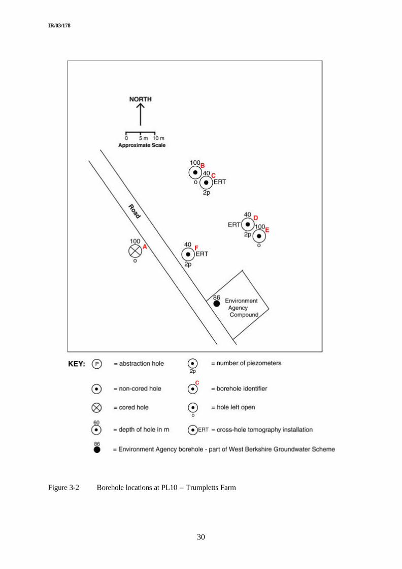
PL10 – TRUMPLETTS FARM
This site consists of three 100m deep open boreholes and three 40m deep holes which were completed with Electrical Resistive Tomography (ERT) arrays (for cross hole tomography) and piezometers at different depths – see Figure 3-2 for the site layout and Table 3-3 for completion details. The three 100m deep holes were only cased to around 20m at which depth competent chalk was encountered, enabling open hole completion from there to full depth. Tracer and packer tests can be carried out in any combination of the three 100m holes while monitoring heads in these deep holes and in the piezometers in the 40m deep holes. Additionally the site is adjacent to one of the Environment Agency’s Thames Groundwater Scheme boreholes (see Figure 3-2) and the possibility exists for heads in all six holes to be monitored during abstraction from the Agency’s hole – but only with their prior approval and co-operation. The ERT arrays were designed by Lancaster University and installed specifically for use in research projects with which they are involved. The data from these ERT arrays during packer and tracer test will provide important information on the flow hydraulics and transport of tracers at this site.
PL11 – FRILSHAM MEADOW
This site consists of 11 boreholes drilled to differing depths and of differing completions as shown in Figure 3-3 and Table 3-3. This is also the location of one of the seven recharge sites installed in the Pang/Lambourn catchment – see section 3.7.6.
It was originally planned that the three 40m open boreholes (PL11A, PL11B, PL11C) would only be cased to around 5m thus allowing some 35m of open hole for packer testing. However, it was found that the chalk was well fractured to a depth between 16 and 20m and it was therefore necessary to case these holes to such depths in order to prevent collapse. In order to gain information on the shallower zone, through which it was assumed significant flow to and/or from the river must be occurring, three additional 5m holes were drilled (PL11I, PL11J and PL11K). These three additional holes, the other three 40m deep holes (PL11D, PL11F and PL11G) and the 60 m non-cored hole (PL11H) were all completed with piezometers and ERT arrays (for cross hole tomography) as shown in Figure 3-3, Table 3-3 and Table 3-4. Hole PL11E was drilled to a total depth of 85.5m. The original design had been to core to a total depth of 60m, however results from this site and PL13 indicated that it would be worth drilling on to a greater depth in order to penetrate the Chalk Rock – generally a significant flow horizon. Due to budgetary constraints it was not possible to core to full depth and so core was only collected to a total depth of 61m.
3.7.2 Groundwater divide
When planning the hydrogeological infrastructure for the Pang catchment it became evident that there was insufficient existing information to monitor the position of the groundwater divide between the Pang and the River Thames. It was, therefore, planned to drill four boreholes to help locate it. Two holes (PL13 and PL28) were sited initially with the intention that a further two would be sited following initial inspection of the results. The cost of the second two holes could not be covered following cuts in the drilling budget and so were not drilled.
PL13 (Broadfield cottages) and PL28 (Beche Park Wood) were drilled to 126m and 100m respectively. PL13 was cored to full depth and had multi-piezometer completion as shown in Table 3-3. PL28 was left open hole and provides groundwater level information for the recharge site (see 3.7.6) also located in Beche Park Wood.

IR/03/178
28
3.7.3 Interfluve to valley profile
Sites PL14, PL25 and PL11 were located to provide a profile from the top of an interfluve (PL14) down to a valley bottom (PL11). Site PL11 has already been described in section 3.6.1.
An initial borehole commenced at site PL14 had to be abandoned due to problems encountered in drilling through the Palaeogene deposits. The further borehole, PL14B (Grimsbury Wood), is a single borehole drilled through the Palaeogene cover into the Chalk to a total depth of 56m. The Palaeogene cover is unconsolidated and, in order to remain on budget and also regain lost time, it was decided to only core in the Chalk. There was no water strike in the Palaeogene deposits during drilling and so there was no piezometer installed in the cover, indeed the Palaeogene cover was completely cased out to prevent its collapse. Once stable Chalk had been encountered (at 33m) the hole was left open for the remainder of its depth. A single pressure transducer was installed to permit monitoring of water levels and this also provides information for the recharge site (see 3.7.6) located here.
PL25 is a single borehole site but completed with pressure transducers installed to monitor heads at three different depths (see Table 3-3).
3.7.4 Wetland investigation
Site PL26 consists of a total of 8 boreholes located on either sides of the River Lambourn at Boxford (see Figure 3-4). Boreholes PL26A, PL26C, PL26D, PL26E and PL26F are drilled in the flood plain of the river while PL26G, PL26H and PL26I are located on the Chalk outcrop which rises northwards from the valley. The depths and completions of the individual holes are given in Table 3-3. The site is immediately west of a candidate Special Area of Conservation as designated under the EC’s Habitats Directive (Council Directive 92/43/EEC). The Environment Agency is investigating this cSAC in order to understand its hydraulic regime; they are working closely with the LOCAR programme and will make their data available to the LOCAR Data Centre. Borehole PL26F has been completed open hole and to a larger diameter (250mm) than the other holes at this site to provide the opportunity for pumped abstraction of groundwater.
3.7.5 Surface water groundwater interaction
At sites PL02 (Frogmore Farm), PL11 (Frilsham Meadow) and PL26 (Boxford), the opportunity exists for investigation of surface water/groundwater interaction. The borehole layouts at Sites PL11 and PL26 have been described above. One of the research projects has also installed single pressure transducers in the river at both sites to provide data on river stage.
PL02 is a single, 21m deep borehole located approximately 10m from the River Pang. The borehole experienced artesian flow following completion but prior to equipping. Therefore, vented pressure transducers (with an associated barometric pressure transducer) were installed and a secure cover plate fitted to the surface casing to contain the flow whist allowing continuous measurement of heads. As part of the LOCAR hydrological infrastructure a Starflow ultrasonic Doppler instrument has been installed in the River Pang at this location to provide data on river flow along with a Wiser installation to provide river water quality data. These two river instruments are referenced as site PL20.
3.7.6 Recharge sites
Sites PL11, PL14, PL 16, PL28, PL29 are located at LOCAR recharge sites which have been installed as part of the LOCAR hydrological infrastructure. The purpose of recharge sites is

IR/03/178
29
to monitor the movement of water and solutes as they move from the atmosphere, through the vegetation cover, to the land surface and then through the unsaturated zone to the groundwater table. To achieve a representative picture of the behaviour of the catchment as a whole, they are sited on a range of soil types and land use domains and consist of an area of land (of the order of 30 m square) equipped with a variety of instruments including rain gauges, automatic weather stations, neutron probe access tubes, automatic soil water content instruments, equitensiometers, tensiometers, soil water samplers and data loggers. To monitor the impact of the recharge on the water table, each recharge site requires a borehole to allow the measurement of variation in groundwater levels with time. Thus these five boreholes allow collection of this information for their respective recharge sites. Additionally at PL14, PL28 and PL29, tensiometers will be mounted in the boreholes themselves to record soil water potential deep in the profile.
IR/03/178
30
Figure 3-2 Borehole locations at PL10 – Trumpletts Farm

IR/03/178
31
Figure 3-3 Borehole locations at PL11 – Frilsham Meadow

IR/03/178
32
Figure 3-4 Borehole locations at PL26 - Boxford

IR/03/178
33
4 Data
4.1 INTRODUCTION
The LOCAR Steering Committee has delegated responsibility for its data and implementation of its data policies to the Centre for Ecology and Hydrology and the British Geological Survey. They established the LOCAR Data Centre, as part of the National Water Archive to be responsible for all LOCAR data. It is important to distinguish the Data Centre's responsibility for data from actual data custody itself. In some cases data will be physically transferred to the Data Centre, for example, the results of the field programme, while in others, the Data Centre will keep records of where data are held.
The aim of the Data Centre is to create an integrated, quality controlled, quality assured database readily accessible to LOCAR scientists by all appropriate contemporary means and which appears seamless to the outside user.
Data held by the Data Centre can essentially be divided into four groups:
• Existing time independent data sets from other agencies.
• Data collected as part of the LOCAR Infrastructure installation exercise.
• Monitoring data. This includes historic and current data collected by other agencies (e.g. the Environment Agency) and data collected by the relevant Catchment Service Team following installation of the LOCAR infrastructure.
• Data collected as part of individual LOCAR research projects.
The hydrogeological data sets collecting during and/or as a result of the infrastructure installation exercise are discussed below. The storage of and access to these and all LOCAR data sets are governed by the LOCAR data policy which can be found at:
http://www.nerc.ac.uk/funding/thematics/locar/datapolicy.shtml
4.2 DATA SETS
4.2.1 Collected during the infrastructure installation phase
Table 4-1 shows the various data sets collected during the infrastructure installation phase.
4.2.2 Monitoring data
GROUNDWATER HEADS
Table 3-3 shows the depths at which MiniTroll recorders are installed in the Pang/Lambourn infrastructure boreholes. These MiniTrolls were initially set up to record heads at 60-minute intervals and it is intended that they will be downloaded on a monthly basis. However, they are capable of storing up to 30,000 data points and have a reported minimum battery life of 1.5 years.
GROUNDWATER QUALITY
In order to provide regular groundwater quality data from the catchment, budgetary provision has been made for 15 groundwater samples to be collected and analysed on a monthly basis. Recommendations for sample sites have been made and are currently under discussion with the Catchment Service Team (CST) who will be responsible for collecting the samples. The

IR/03/178
34
CST is considering the proposed sample collection regime and the amount of time required to complete it. The main factors involved are the time involved in accessing the individual sites with the appropriate sampling equipment and the time required to purge the boreholes/ piezometers before a representative sample can be collected.
Table 3-3 shows those sites proposed for groundwater sample collection.
Table 4-1 Data sets available for LOCAR boreholes in the Pang/Lambourn catchment
Frog
mor
e Fa
rmTr
umpl
etts
Far
m
Trum
plet
ts F
arm
Trum
plet
ts F
arm
Trum
plet
ts F
arm
Trum
plet
ts F
arm
Trum
plet
ts F
arm
Fril
sham
Mea
dow
Fril
sham
Mea
dow
Fril
sham
Mea
dow
Fril
sham
Mea
dow
Frils
ham
Mea
dow
Fril
sham
Mea
dow
Fril
sham
Mea
dow
Fril
sham
Mea
dow
Fril
sham
Mea
dow
Fril
sham
Mea
dow
Fril
sham
Mea
dow
Bro
adfie
ld C
otta
ges
Grim
sbur
y W
ood
Grim
sbur
y W
ood
Hig
hfie
ld F
arm
Hig
hfie
ld F
arm
Pik
es R
owB
oxfo
rdB
oxfo
rdB
oxfo
rdB
oxfo
rdB
oxfo
rdB
oxfo
rdB
oxfo
rdB
oxfo
rdB
oxfo
rdB
eche
Par
k W
ood
Fol
ly D
own
PL
2AP
L10
A
PL1
0BP
L10C
PL1
0DP
L10E
PL1
0FP
L11A
PL1
1BP
L11C
PL1
1DP
L11
EP
L11F
PL1
1GP
L11H
PL1
1IP
L11J
PL1
1KP
L13
AP
L14A
PL1
4B
PL1
6AP
L16
(WE
LL)
PL2
5AP
L26A
PL2
6BP
L26C
PL2
6DP
L26E
PL2
6FP
L26
GP
L26H
PL2
6IP
L28A
PL2
9A
Drillers daily sheets √ √ √ √ √ √ √ √ √ √ √ √ √ √ √ √ √ √ √ √ √ √ √ √ √ √ √ √ √ √ √ √ √ √Borehole completion forms √ √ √ √ √ √ √ √ √ √ √ √ √ √ √ √ √ √ √ √ √ √ √ √ √ √ √ √ √ √ √ √ √ √Downhole geophysical logs √ √ √ √ √ √ √ √ √ √ √ √ √ √ √ √ √ √ √ √ √ √ √ √ √ √ √ √Surface geophysics √ √ √ √ √ √ √ √ √ √ √ √ √ √ √ √ √ √ √ √ √ √ √ √ √ √ √ √Transducer installation √ √ √ √ √ √ √ √ √ √ √ √ √ √ √ √ √ √ √ √ √ √ √ √ √ √ √ √ √ √ √ √ √Geological core log √ √ √ √ √ √Drill cuttings log √ √ √ √ √ √ √ √ √ √ √Hydrogeological core log √ √ √ √ √ √ √Physical properties analysis √ √ √ √ √ √Pore &/or depth chemical analysis √ √ √ √ √ √ √ √ √ √ √ √ √ √ √ √ERT Arrays √ √ √ √ √ √ √ √ √ √ √ √
Borehole PL14A was abandoned during drilling due to rig failureBorehole PL26B was abandoned during drilling when bit was lost in hole and could not be retrieved.
Bold lettering indicates cored boreholes

IR/03/178
35
5 Equipment
A limited amount of equipment was purchased using LOCAR infrastructure funds to both enable the Catchment Service Teams to collect groundwater samples at regular intervals at selected sites within the catchments and to provide a central pool of specialist equipment for use by researchers within the LOCAR community. The following is a list of that equipment:
• DIPMETERS
o 3 x 100M dip meters
o 3 x 8m pocket dip meters
o 1 x 60m logging dip meter with associated software and connection cable
• MICROPURGE GROUNDWATER SAMPLING EQUIPMENT
o 1 x Sample Pro Pump Consultants Kit (¼” and ¼” Push In fittings) with controller, hose, hose-reel and portable petrol air compressor.
• WATERRA GROUNDWATER SAMPLING EQUIPMENT
o 1 x Power Pack PP1/ backpack & SA
o 3 x hand operated groundwater sampling systems (32mm OD and 21mm ID) with 3 x 60m hose each system and necessary ancillaries.
• ARCHWAY PACKER EQUIPMENT
o 2 x 88-185mm double packers with ancillary equipment
• GRUNDFOS GROUNDWATER SAMPLING PUMP
o 1 x MP1 monitoring/sampling pump with 80m cable, generator and power converter.
The dipmeters and groundwater sampling equipment are primarily for use by the Catchment Services Teams (who are also purchasing additional sampling equipment) and can’t be considered as being available to individual research projects. However the packers can be accessed through the Catchment Service Teams and it is recommended that requests for its use are made with as much notice as possible due to the possibility of demands from several researchers at the same time.

IR/03/178
36
6 References
Adams B., Peach D.W., and Bloomfield J.P. 2003(b). The LOCAR hydrogeological infrastructure for the Frome/Piddle catchment. British Geological Survey Internal Report, IR/03/179.
Adams B., Peach D.W., and Bloomfield J.P. 2003(c). The LOCAR hydrogeological infrastructure for the Tern catchment. British Geological Survey Internal Report, IR/03/180.
Aldiss D.T. and Royse K.R. 2002. The geology of the Pang-Lambourn catchment, Berkshire. British Geological Survey Commissioned Report, CR/02/298N
Berrie A. 1973. Ecological study of the river Lambourn. Report for the period October 1970-September 1973. Department of Zoology, University of Reading.
Bristow R., Mortimore R., and Wood C. 1998. Lithostratigaphy for mapping the Chalk of southern England. Proceedings of the Geologists’ Association, 109, 293-315.
Johnson I.W., Elliott C.R.N., Gustard A., Armitage P.D., Ladle M., Dawson F.H. and Beaumont W.R.C. 1993. Ecologically acceptable flows – assessment of the Instream Flow Incremental Methodology. R&D Report 282, National Rivers Authority, Bristol.
Neal C., Williams R.J., Neal M., Bhardwaj L.C., Wickham H. and Harrow M. 2000. The water quality of a tributary of the Thames, the Pang, in southern England. Science of the Total Environment, vol. 251/252, pp 459-476.
Peach D.P., Adams B., Hudson J., Leeks G. and Armitage P. 2004. LOCAR/JIF proposals for infrastructure and monitoring on the LOCAR catchments. British Geological Survey Internal Report, CR/04/131N.
TerraDat (UK) Ltd. 2002. Surface geophysical surveys in three British catchment areas – the Frome/Piddle, Tern and Pang/Lambourn. Contribution to Lowland Catchment Research (LOCAR), carried out for NERC.
Wright J.F. and Symes K.L. 1999. A nine-year study of the macro-invertebrate fauna of a chalk stream. Hydr. Processes, 13, pp 371-385.

IR/03/178
37
Appendix 1 Contents of the LOCAR Site Completion files held by the Catchment Service Teams and the LOCAR Data Centre.
1. Site Summary
This includes a brief site description, a summary of the land agreement and any other relevant information (e.g. name of the landowner and any neighbours who may have an interest in activities on site)
2. Maps & Diagrams
Details of site layout.
3. Photographs
Some before and after installation shots.
4. Land Agreement
A copy of the land agreement between NERC and the landowner.
5. Health and Safety
Site risk assessment, a copy of the catchment hazard identification matrix (i.e. a table of a range of hazards and sites at which they exist)
6. Specifications
Specifications of equipment installed at the site.
7. Manuals
Generally equipment manuals will be held separately by the Catchment Service Teams.
8. Calibration
Calibration details of installed equipment
9. Variables
Details of the variables recorded by the installed equipment.
10. Appendices
Data sets collected during infrastructure installation. Where appropriate will include:
• Indication of downhole geophysical logs that were carried out
• Results of the site levelling survey carried out using Trimble GPS RTK equipment.
• Chemical analyses of water samples collected during drilling.
• Lithostratigraphical log – the geological description of the core.
• Indication of any surface geophysical surveys carried out.
• Borehole completion details.
• Site Audit sheets summarising casing and piezometer completions and installation depths of MiniTrolls.

IR/03/178
38
• MiniTroll and cable Quality Inspection reports.
• Cross Hole Tomography electrode installation details.
• Description of drilling samples.
• Hydrogeological log of core.
• Physical properties of core samples
• Chemical analyses of pore waters collected from core samples.
• Drillers’ day sheets.