Embed Size (px)
Citation preview

The Little Wonder Modular145-200
Installation, Operation & Maintenance
Village Marine LWM 145-200
Part Number: 95-0024


TABLE OF CONTENTS
vVMT- v. MARCH 2013
1.0 INTRODUCTION 1
1.1 UNPACKING AND HANDLING 2
1.2 PERFORMANCE SPECIFICATIONS 2
1.3 ENVIROMENTAL REQUIREMENTS 2
1.4 CONSUMABLES 3
1.5 MAINTENANCE EQUIPMENT 3
2.0 INSTALLATION 4
2.1A TO CONNECT PLUMBING 4
2.1B TO CONNECT THE ELECTRICAL 7
3.0 GENERAL THEORY OF OPERATION 8
3.1 REVERSE OSMOSIS THEORY 8
3.2 APPLICATION OF REVERSE OSMOSIS 8
3.3 PRODUCT WATER QUALITY STANDARDS 9
3.4 FACTORS AFFECTING PERMEATE PRODUCTION 10
3.4A TEMPERATURE CORRECTION FACTOR 11
4.0 OPERATION 12
4.1A TO START THE LITTLE WONDER MODULAR UNIT 12
4.1B TO SHUT DOWN THE UNIT 13
5.0 MAINTENANCE 14
FRESHWATER FLUSH / SHORT TERM STORAGE 14
5.1 TO FLUSH THE LITTLE WONDER MODULAR UNIT 15
5.2 MEMBRANE CLEANING AND PRESERVATION 16
5.3 CLEANING CHEMICALS 16
5.4 WHEN TO CLEAN 16
STEPS FOR CLEANING CHEMICALS #1, #2, AND #3 (CARTRIDGE FORM) 17
5.5 OIL CHANGE PROCEDURE 18

TABLE OF CONTENTS
vi VMT A v. MARCH 2013
6.0 MEMBRANE REPLACEMENT 20
6.1 PRESSURE VESSEL DISASSEMBLY 20
6.2 PRESSURE VESSEL ASSEMBLY 21
7.0 FREEZE PROTECTION 22
8.0 TROUBLESHOOTING 24
9.0 PLUMBING DIAGRAMS 25
10.0 PARTS REFERENCE 27
11.0 MANUFACTURER’S LITERATURE 28

SYSTEM START UP LOG
viiVMT- v. MARCH 2013
Village Marine Tec.Fresh Water from the Sea
SYSTEM START UP LOG
SYSTEM INFORMATION:
MODEL NUMBER:
SERIAL NUMBER:
DATE OF PURCHASE:
PURCHASED FROM:
INSTALLATION DATE:
START UP PERFORMANCE READINGS:
MEASURE AFTER 3 AND 24 HOURS OR PRESSURIZED TIME IN SIMILAR CONDITIONS
3 Hours 24 Hours
FEED WATER TEMPERATURE:
FEED WATER SALINITY (IF KNOWN):
BATTERY VOLTAGE:
VOLTAGE AT UNIT:
AVERAGE AMP DRAW (IF KNOWN):
OPERATING PRESSURE:
PRODUCT WATER FLOW: (GPH) (GPH)
REJECT WATER FLOW (IF KNOWN): (GPH) (GPH)
PRODUCT WATER QUALITY (IF KNOWN): (ppm) (ppm)


INTRODUCTION
1VMT- v. MARCH 2013
1.0 INTRODUCTION
SYSTEM DESCRIPTIONVillage Marine Tec’s (VMT) Little Wonder watermakers are well-engineered reverse osmosis (RO) systems,designed and built for simple operations and maintenance for the cruising sailor, or sport fisherman, or where spaceis at a premium. These modular 12 Volts DC desalination systems will produce seven to eight gallons per hour (GPH)of freshwater from the sea (gallon production will vary based upon water temperature, salinity, and model of the ROsystem).
The Little Wonder unit produces water, meeting or surpassing drinking water guidelines with seawater saltconcentrations as high as 32,000 parts per million (ppm).
HOW TO USE YOUR MANUALThis User Guide & Reference Manual contains important information about the safe operation and maintenance ofyour Little Wonder Vertical units.
We advise you to please read through the entire User Guide & Reference Manual carefully to ensure you familiarizeyourself with the operation of your RO system and follow the recommendations within the manual, to help make yourwater producing experiences trouble-free and enjoyable.
SAFETY WARNINGSThroughout this User Guide & Reference Manual you will see many important statements or labels indicated on theproduct with the following words:
Indicates a strong possibility of severe personal injury or death ifwarning instructions are ignored.
Indicates hazards or unsafe practices of product may causeminor personal injury or may cause property damage.
NOTE: Text specifies useful information.

INTRODUCTION
2 VMT A v. MARCH 2013
1.1 UNPACKING AND HANDLING
The Little Wonder reverse osmosis units are shipped pre-assembled, however, connection of themodules will be required. Inspect the RO unit to verify it was not damaged in transit. Also, please referto the plumbing diagram to verify all components for the watermaker are shipped prior to installation.
DO NOT EXPOSE THE RO UNIT TO FREEZING TEMPERATURES WITHOUT PROPER STEPS TOTREAT THE RO UNIT FOR SUB-FREEZING TEMPERATURES.
1.2 PERFORMANCE SPECIFICATIONS
Parameter SpecificationRaw water temperature (minimum) 33 F (1C)Raw water temperature (nominal) 77 F (25C)Raw water temperature (maximum) 113 F (45C)Min. raw water inlet pressure Flooded suction pressureMax. raw water inlet pressure* 30 psiFlush water recommended max. pressure* 35 psiDesign RO element pressure 800 psiMax. RO element pressure 1000 psiMax. feedwater chlorine residual < 0.1 ppmCleaning solution pH range 10-11 (chem. 1), 2-3 (chem. 2)Membrane type Thin film composite
Table 1.0 - Performance Characteristics
* For inlet pressure greater than recommended limits, install pressure regulator.
NOTE: REGARDING WATER PRODUCTION:The RO series number (i.e. LWM 145, LWM 200) refers to gallons per day (GPD) production producedwith new membranes at design optimum conditions.
To achieve optimum production:(1) The feed flow must be unrestricted (positive water pressure at the inlet to high pressure pump).(2) Seawater temperature at 77F (25C).(3) Seawater salinity at 32,000 parts per million (ppm) total dissolved solids (TDS).(4) Direct current (DC) units should be at charging voltage (13.8 volts for a 12 volt system) and wire
size should be 6 gauge.
Variation of conditions (environmental, temperature, and frequency of use) and normal aging ofmembranes will decrease production. Normal membrane fouling will be partially recovered by chemicalcleaning, but 100% recovery should not be expected. Production rates from membrane to membranecan vary + 15%.
1.3 ENVIROMENTAL REQUIREMENTS
Parameter SpecificationsList (Permanent):Trim (Fore and Aft):Pitch:Roll:
15+ 3010 (6 sec cycle)30 (12 sec cycle)
Table 1.1 - Nominal Operating Conditions

INTRODUCTION
3VMT- v. MARCH 2013
1.4 CONSUMABLES
Table 1.2 lists the consumables required for the RO unit. Use ONLY Village Marine Tec. approved filtersand chemicals.
LW 145/200Description QTY VMT Part No.
Chemical Cleaning Cartridge Kit #1, #2 1ea/box 85-0102Preservative Cartridge Kit, Chemical #3 2/box 85-0103Filter, 5 micron, 10 sq-ft. 1ea 33-0117Filter, Carbon, 10 sq-ft. 1ea 33-0311Aqua Pro High Pressure Pump Oil 1 qt 85-0050
Table 1.2 – VMT Approved Consumables
1.5 MAINTENANCE EQUIPMENT
Table 1.3 lists the test equipment required for performance verification and maintenance of the RO unit.
Description VMT Part No.
Kit, Pump, Service 70-6181Economy Mini Water Tester, TDS 99-1990
Table 1.3 – Maintenance Equipment List

INSTALLATION
4 VMT A v. MARCH 2013
2.0 INSTALLATION
Village Marine Tec. recommends installing the RO unit in a dry sheltered location at or aft of midship,with drainage underneath (to draw off standing water when performing routine maintenance or service).The portion of the watermaker up to and including the high pressure pump should be installed BELOWwaterline (Refer to Figure 2.1). If the high pressure pump cannot be below waterline, then contact yourVMT distributor for the high lift LP pump, p/n 70-0512. The pressure vessel tube and instruments canbe ABOVE waterline. Give consideration to extra space around the RO unit, allowing access for theunit’s maintenance (i.e. membrane replacement, oil change, prefilter replacement, or other service).
Figure 2.1: Recommended installation BELOW waterline.
Locate or create a ½” dedicated through-hull for the feedwater intake of the RO unit. The through-hullmust be attached with a ball valve (seacock), and optionally a sea strainer.
The Little Wonder MODULAR SHOULD NOT SHARE a through-hull feedwater intake. VillageMarine Tec. recommends the Little Wonder HAVE its OWN dedicated through-hull, to properlyfeed water into the RO. Avoid connecting the inlet piping to any water line which services anengine or other equipment. Air could be drawn through the unit causing damage to the RO unit’spumps, as well as VOIDING the RO unit’s warranty with VMT.
2.1a TO CONNECT PLUMBING
Step 1: Refer to Section 9 for the EXPANDED detailed Little Wonder MODULAR plumbing diagram.
Figure 2.1: Little Wonder MODULAR Plumbing Diagram.

INSTALLATION
5VMT- v. MARCH 2013
FEEDWATER INTAKE
Step 1: Mount the sea strainer BELOW the vessel’s waterline.
Step 2: Mount the three-way manual Freshwater Flush Valve (attached to Carbon Filter Housing) BELOWwaterline. Refer to Figure 2.3 for a view of the carbon filter and freshwater flush valve.
Figure 2.2: Carbon Filter with Freshwater Flush Valve – Isometric Views.
NOTE: Village Marine Tec. recommends the Manual Freshwater Flush Assembly be installed BELOWwaterline. However, the valve can be removed from the filter housing and relocated belowwaterline, leaving the filter housing ABOVE waterline. A hose can be plumbed from the filterhousing to the valve. This way the seawater feed does not go above waterline to avoid trappingair and creating a priming problem.

INSTALLATION
6 VMT A v. MARCH 2013
Figure 2.4: Connecting the Carbon Filter Outlet to the Separated Freshwater Flush Valve.
Step 3: Connect ½” diameter PVC hoses to connect all the feed water components up to the high pressurepump. Note the boost pump outlet is a 3/8” diameter barb fitting. Use a short section of 3/8” hose andjump to ½” diameter using the step size adaptor supplied.
BRINE DISCHARGE
Locate a convenient spot in the boat to install an overboard discharge through-hull with an ½” diameter.Discharge line is required to be ABOVE waterline. Refer to Figure 2.1. If connecting to a common drain,tee in from above so that backflow contamination to the watermaker from other drains is not possible.
PRODUCT WATER AND SAMPLE WATER
Connect a ¼” diameter PVC hose (or potable water hose) from the product elbow off the back of theproduct flowmeter to a sample valve (Refer to Figure 2.5). On both outlets of the sample valve, connecta ¼” inner diameter PVC hose (or potable water hose), one hose for product water sampling and theother hose for feeding the ship’s Freshwater Tank. The product tank hose off of the sample valve is tobe fed into the top of the product tank, to prevent any possible backflow (refer to Figure 2.1).
Figure 2.5: Little Wonder MODULAR Sample Valve Connection.
If a fitting connection cannot be made to the top of the Freshwater Tank, tee into the Deck Water Fill.
Leave enough hose length to RUN the sample hose portion to a sink, bilge, or overboard, to sample thewater.
NOTE: Village Marine Tec. recommends running the sample line to a galley sink and installing adedicated water spigot, free flowing, always open (i.e. a ‘cane shaped’ fixture as used in amanual galley pump). This allows easy sampling at a sink, a drain overboard and the capabilityto fill extra water bottles, while your Little Wonder produces water for all purposes.
FRESHWATER FLUSH
Tap into your boat’s freshwater pressure system (Tee into the cold pressurized side) with a ½” diameterhose to the carbon flush filter. If the freshwater pressure on board is above 35 psi, install a pressureregulator.

INSTALLATION
7VMT- v. MARCH 2013
2.1b TO CONNECT THE ELECTRICAL
TURN OFF ALL ELECTRICAL POWER FOR USE WITH THE RO UNIT PRIOR TO CONNECTING TOTHE RO POWER SOURCE. FAILURE TO DO SO MAY RESULT IN SERIOUS INJURY OR DEATHTO PERSONS HANDLING THE UNIT.
NOTE: Adhere to all electrical codes and regulations governing the installation and wiring of electricalequipment. Typical codes specify the type and size of conduit, wire diameter, and class or wireinsulation depending upon the amperage and environment.
NOTE: The power supply should always be of greater service rating than the requirements of the ROunit. This will assure proper voltage even if power supply voltage is slightly less than required.Never connect the RO unit to a line that services another electrical device. THE RO UNITSHOULD HAVE ITS OWN INDEPENDENT POWER SUPPLY.
Step 1: Verify all power switches and power sources are in the OFF position.
Step 2 Connect power source wire (Positive +) to line side on RO unit’s breaker.
Step 3: AC POWERED 110V/220V Little Wonder MODULAR:Connection will be from the separate control box supplied to the onboard circuit breaker panel. VMTrecommends use of a 15 amp fuse or circuit breaker.
DC POWERED 12V Little Wonder MODULAR:12 VDC units require 6 gauge wire and a 25 amp fuse or circuit breaker. Connect RO unit’s powersupply red wire (Positive +) from load side of unit’s breaker, to power input on the Little WonderMODULAR’s terminal strip (Refer to Figure 2.6).
Step 4: Connect a negative black wire from the ground bus bar behind main breaker panel to negative powersource input on unit.
Step 5: With the DC units, connect the boost pump wires red and black to the same terminals at the side of thehigh pressure pump as shown in figure 2.6.
Figure 2.6: Little Wonder MODULAR (DC UNIT) Electrical Interface Views.

GENERAL THEORY
8 VMT A v. MARCH 2013
3.0 GENERAL THEORY OF OPERATION
3.1 REVERSE OSMOSIS THEORY
Reverse osmosis, like many other practical scientific methods, was developed from processes firstobserved in nature. Osmosis is a naturally occurring phenomenon in which a semi-permeablemembrane separates a pure and a concentrated solution (a semi-permeable membrane is defined asone that preferentially passes a particular substance). Every fluid has an inherent potential that isdirectly related to the type and amount of solids in solution. This potential, referred to as osmoticpressure, increases in proportion to relative concentration of a solution. A concentrated solution,therefore, has an osmotic pressure that is higher than that of a pure solution.
In an osmotic system, the less concentrated solution will attempt to equalize the concentrations of bothsolutions by migrating across the semi-permeable membrane. When enough pure solution migratesacross the membrane such that the inherent potential difference between the solutions in no longerhigher than the osmotic pressure of the membrane, the purer solution will stop flowing. If the pressureon the concentrated solution is increased to above the osmotic pressure, fluid flow will be reversed. Thiscondition, called Reverse Osmosis, can be established by artificially pressurizing the more concentratedsolution using a high pressure pump. In this type of system, the concentrated solution (normally referredto as feedwater) will become more concentrated as pure water flows out of solution and across themembrane to the permeate side. Discounting the effects of feedwater temperature and salinity, theoperating pressure normally required to produce significant amounts of pure water is at least twice theosmotic pressure of the membrane being used.
SALINE
SOLUTION
PURE
SOLUTION
SEMI-PERMEABLE MEMBRANE
ATMOSPHERIC
PRESSURE
(14.7 PSI)
SALINE
SOLUTION
PURE
SOLUTION
HIGH
PRESSURE
(800 PSI)
OSMOSIS REVERSE OSMOSIS
Figure 3.1 - Simple (Reverse) Osmosis Process.
3.2 APPLICATION OF REVERSE OSMOSIS
Seawater contains many kinds of solids dissolved in solution. The most prevalent is common table salt(sodium chloride). Other minerals that may be present in solution are substances that usually containvarious compounds of calcium and sulfate. The sum of all of the solids dissolved in a particular sampleof water is referred to as Total Dissolved Solids or TDS. Seawater normally averages 32,000 ppm(parts per million) TDS although variations of 5000 ppm are common in various parts of the world. Thefundamental goal of any desalination process is a significant reduction in the amount of dissolved solidsin water.
In a Reverse Osmosis desalination system, most of the dissolved solids do not pass through themembrane but are instead carried along the membrane surface. This rejected water, referred to asbrine, becomes increasingly more concentrated as it flows across the surface of the membranes and iseventually piped to drain. The product water that flows through the membrane is referred to aspermeate. The percentage of feedwater that enters the unit converted to permeate is called the

GENERAL THEORY
9VMT- v. MARCH 2013
recovery rate. A higher than optimal recovery rate (which can be obtained by increasing the backpressure on the unit above the recommended range) results in greatly increased membrane foulingrates and a significant decrease in the operational life of the membranes.
It should be noted that no system is capable of removing all 100% of the dissolved solids fromseawater. Designed to reject approximately 99% of the TDS, the system allows 1% of the 32,000 ppmTDS in the seawater to pass into the product water. This yields product water of less than 500 ppm, therecommended TDS for drinking water. A system such as this is said to have a salt passage of 1%.
Figure 3.2: Simplified Schematic of an RO System.
3.3 PRODUCT WATER QUALITY STANDARDS
This RO unit will produce permeate (product water) with a quality of less than 500 ppm TDS and inaccordance with World Health Organization (WHO) guidelines for drinking water. General WHOspecifications for acceptable drinking water quality are as follows:
Table 3.0 - WHO Drinking Water Guidelines.
Constituent Ion / Molecule Maximum Limits (ppm)Nitrate 10Fluorine 1Sulfate 100Magnesium 30Calcium 75Calcium Carbonate 100Iron 0.1Manganese 0.05Total Dissolved Solids 500Turbidity 5Oil 0.1Detergents (Anionic) 0.2Phenols 0.001Bacteria – E. Coli (per 100 ml) 0

GENERAL THEORY
10 VMT A v. MARCH 2013
3.4 FACTORS AFFECTING PERMEATE PRODUCTION
VARIATIONS IN TEMPERATURE, PRESSURE, AND SALINITY
The following table illustrates how the quality and quantity of permeate produced by a RO system isaffected by changes in temperature, salinity and pressure:
With constant.... And increasing....Permeate
TDS CapacitySalinity and Pressure Temperature Increases Increases
Temperature and Pressure Salinity Increases DecreasesTemperature and Salinity Pressure Decreases Increases
Table 3.1 - Factors Affecting Permeate Quality
The RO system can be adjusted to maintain a constant permeate output when feedwater temperatureand salinity is other than nominal. The operator can do this by controlling system pressure manually viathe backpressure regulation valve located in the system brine piping. As permeate flow decreases, theoperator can throttle the pressure regulation valve closed to increase system pressure. This, in turn,will increase the permeate output and mitigate the effect of a decrease in temperature or an increase insalinity. Conversely, the operator can open the pressure regulation valve to reduce pressure andpermeate flow in areas of excessively high temperature or low salinity.
IN FRESH OR BRACKISH FEEDWATER CONDITIONS, MAKE SURE TO REDUCE PRESSURE BYTURNING REGULATOR. SET PRESSURE SO PRODUCT FLOW IS NO MORE THAN 120% OFDESIGN FLOW TO AVOID MEMBRANE DAMAGE.

GENERAL THEORY
11VMT- v. MARCH 2013
3.4a TEMPERATURE CORRECTION FACTOR
As previously described, the output capacity of any RO unit is highly dependent on feedwatertemperature. In order to quantify this relationship, operational data has been utilized to developTemperature Correction Factors (TCF). The TCF (which is compensated to 25°C/77°F) is used todetermine what part of any change in system output flow is due to variations in feedwater temperaturealone. This, in turn, allows the operator to establish the baseline flow for a given temperature, allowingmore accurate troubleshooting. The procedure for calculating the TCF and the temperaturecompensated flow is as follows:
1) Measure sea water temperature.2) Determine the corresponding correction factor from Table 3.2 based on the measured temperature.3) Note the product flow rate at the Product Flow meter.4) Multiply the measure (uncorrected) product flow meter flow rate by the correction factor from Table
3.2 to give the calculated system output under standard conditions (25°C).
Example:Raw water temp: 15°CTCF: 1.47Actual product flow: 5.67 (gph)Calculation: 5.67 x 1.47 = 8.3349 (gph)Calculated product flow: 8.3 (gph)(Adjusted to 75 F) (This is the normal flow for a LW 200)
°C Factor °C Factor °F Factor °F Factor
1 3.64 26 0.97 34 3.47 84 0.88
2 3.23 26 0.94 36 3.18 86 0.82
3 3.03 28 0.91 38 3.18 88 0.79
4 2.78 29 0.88 40 2.68 90 0.79
5 2.58 30 0.85 42 2.47 92 0.77
6 2.38 31 0.83 44 2.29 94 0.75
7 2.22 32 0.80 46 2.14 96 0.73
8 2.11 33 0.77 48 2.01 98 0.70
9 2.00 34 0.75 50 1.88 100 0.68
10 1.89 35 0.73 52 1.77 102 0.65
11 1.78 36 0.71 54 1.68 104 0.63
12 1.68 37 0.69 56 1.59 106 0.61
13 1.61 38 0.67 58 1.51 108 0.59
14 1.54 39 0.65 60 1.44 110 0.57
15 1.47 40 0.63 62 1.36 112 0.55
16 1.39 41 0.61 64 1.30 114 0.53
17 1.34 42 0.60 66 1.24 116 0.51
18 1.29 43 0.58 68 1.17 118 0.49
19 1.24 44 0.56 70 1.12 120 0.47
20 1.19 45 0.54 72 1.08 122 0.45
21 1.15 46 0.53 74 1.05
22 1.11 47 0.51 76 1.02
23 1.08 48 0.49 78 1.00
24 1.04 49 0.47 80 0.93
25 1.00 50 0.46 82 0.90
Table 3.2 - Temperature Correction Factors

OPERATION
12 VMT A v. MARCH 2013
4.0 OPERATION
4.1a TO START THE LITTLE WONDER MODULAR UNIT
Figure 4.1: Little Wonder MODULAR Instrument Detail.
Step 1: Turn the sample valve to SAMPLE position to direct the flow of water to the sample line.
Step 2: Turn the High Pressure Bypass Valve (Black Valve) to CLEANING POSITION, counterclockwise, torelease air trapped within the system.
Verify the Cleaning Valve (Gray Valve) is positioned to NORMAL discharge, allowing brine water to flowoverboard. Also check the gray Freshwater Flush Valve (Refer to Figure 2.3) is positioned for seawaterintake, NOT freshwater.
FAILURE TO OPEN THE HIGH PRESSURE BYPASS VALVE COULD RESULT IN HYDRAULICSHOCK TO THE SYSTEM.
Step 3: Verify the seawater intake is open at the through-hull. Start-up time can be expedited by filling the pre-filter housing by temporarily turning the flush valve to freshwater position before the RO unit is turnedon.
Step 4: AC POWERED 110V/220V Little Wonder MODULAR Models:Turn Power Switch ON located on the unit’s supplemental control box, to start RO. Start the LP boosterpump first, then the HP pump.
DC POWERED 12V Little Wonder MODULAR Models:Switch ON the breaker at the main breaker panel to power up the unit.
Step 5: Upon initial start-up inspect all plumbing connections in the unit for leakage. Varying temperaturesduring shipment may cause plumbing connections to seep when starting the RO unit for the first time.Secure the unit and repair any leaks before proceeding. Once the leaks are repaired, open the rawwater source and restart the unit.
Step 6: Verify brine discharge is flowing overboard. If so, gradually turn the High Pressure Bypass Valve (BlackValve) to NORMAL/RO position. The High Pressure Regulator is factory set at 800psi. If High Pressure

OPERATION
13VMT- v. MARCH 2013
Gauge does not read 800 psi, slowly tighten or loosen in small increments the screw atop the HighPressure Regulator and adjust to a reading of 800psi. For location of High Pressure Regulator, refer toFigure 4.1.
NOTE: If the RO unit is used for other than seawater purification (in freshwater or brackish waterapplications), reduce pressure as necessary to achieve product flow no greater than 120% ofdesign flow to avoid membrane damage.
RO high pressure production should NEVER EXCEED 950 psi, doing so risks damage to RO unitVOIDING factory warranty.
NOTE: At initial start-up of RO unit, keep the product water diverted out of the water storage tank. IF theunit is filled with preservative storage solution, production must be diverted AT LEAST 10MINUTES to clear preservative solution from system.
Step 7: With the Sample Valve at SAMPLE position, taste the water quality or test it with a hand-held testmeter. If quality is good, turn the Sample Valve over to PRODUCT direction, routing the product waterinto the vessel’s storage tank.
Step 8: Check the RO unit for water leakage periodically at the initial start-up. Observe Product Flow meter.Record the product flow after 3 and 24 hours of operation (use the start up sheet provided on page vii).
4.1b TO SHUT DOWN THE UNIT
Step 1: As the RO unit operates, turn the High Pressure Bypass Valve (Black Valve) to CLEANING POSITION.This will release the high pressure within the RO system.
Step 2: AC POWERED 110V/220V Little Wonder Modular Models:Turn the HP pump off, then the booster pump off at the control box. Then turn OFF your breaker at themain breaker panel.
DC POWERED 12V Little Wonder MODULAR Models:Turn OFF your breaker at the main breaker panel.
The RO unit may be left in this “stand by” condition with the seawater for one day. If the RO unit will beout of service for extended time periods, please refer to the Maintenance section of this manual forflushing instructions.

MAINTENANCE
14 VMT A v. MARCH 2013
5.0 MAINTENANCE
The service life of most system equipment is related to the sea water inlet conditions and proper maintenance. Undernormal conditions, a reverse osmosis membrane (which is the major consumable item) should have an effectiveservice life somewhere between 3 and 6 years.
NOTE: The RO unit must be cleaned when product water output drops by 15%.
Table 5.0: Maintenance Task Chart.
* VMT prefilter cartridges can be rinsed with freshwater and be reused up to 3 times.
** Change pump oil after first 50 hours of RO use. After the first oil change at 50 hours, change thepump oil every 500 hours thereafter or once annually which ever interval comes first.
FRESHWATER FLUSH / SHORT TERM STORAGE
Ideally, the Little Wonder performs optimally when the RO unit is used regularly. The likelihood ofbacterial and biological growth in the membranes increases when stagnant seawater (in extendedperiods) is in contact with the membranes. A freshwater flush procedure is necessary to preventclogging and growth of organic contaminants in the RO system and its membranes. The flush pushesout older stagnant seawater (saltwater) out of the membranes and replacing it with freshwater, leavingless chance of fouling the membranes. The freshwater flush procedure should be used when the unitwill be placed idle or in “stand by” condition for more than one day. Although they do not attack themembranes or other system components directly, high concentrations of biological matter can blockenough of the product water channels to cause a reduction of as much as 40% of the total systemcapacity.
PERFORM A FRESHWATER FLUSH TO THE RO UNIT WITH NON-CHLORINATED FRESH WATERONLY. THE FRESHWATER FLUSH SYSTEM USES A CARBON FILTER INLINE BEFORE SYSTEMTO REMOVE CHLORINE THAT MAY BE PRESENT IN DOCK WATER SUPPLIES.
Da
ily
Wee
kly
Mo
nth
ly
Qu
art
erl
y
Se
mi-
An
nu
ally
An
nua
lly
As
Re
qu
ire
d
La
bo
rH
ou
rs(a
pp
roxim
ate
)
Check Belt Tension/Wear 0.5
Clean/inspect micron prefilter 0.5
Replace 5 micron filter 0.5
Replace carbon flush filter 0.5
Clean membranes 2.0
Replace Membranes 1.0
Check pump oil level 0.1
Change pump oil** 0.5

MAINTENANCE
15VMT- v. MARCH 2013
5.1 TO FLUSH THE LITTLE WONDER MODULAR UNIT
Step 1: Turn the High Pressure Bypass Valve to CLEANING (ensuring zero pressure in system). Verify the grayCleaning Valve is positioned to NORMAL/REVERSE OSMOSIS position.
Step 2: Turn the gray Freshwater Flush Valve to FRESHWATER position. Freshwater should now start flowingthrough the watermaker from the “house” pump.
Step 3: AC POWERED 110V/220V Little Wonder MODULAR Models:Turn the pump switches located on the control box panel to ON position to power up motor. Run unit fortwo minutes.
DC POWERED 12V Little Wonder MODULAR Models:Turn ON the breaker at the main breaker panel and allow the unit to run for two minutes.
Step 4: Turn the gray Freshwater Flush Valve to SEAWATER position. Leave RO unit in standing condition, forup to three weeks. Then reflush or preserve.

MAINTENANCE
16 VMT A v. MARCH 2013
5.2 MEMBRANE CLEANING AND PRESERVATION
This section is to guide the operator in the periodic care and cleaning of the RO membrane elementsused in the LW unit. The basic procedure for all cleaning and preservative treatments is the same – aspecific chemical solution is circulated through the system for a pre-determined length of time.
NOTE: All cleaning and preservation procedures should be performed with freshwater to optimizeperformance of cleaning process.
NOTE: Allow your unit’s product water to run with product to SAMPLE for the first 10 minutes aftercleaning or upon startup after preservation.
Description Cartridge Form Powder Form
Cleaning Chemical #1 1 Cartridge (Blue Stripe) 10 TBSP
Cleaning Chemical #2 1 Cartridge (Red Stripe) 10 TBSP
Preservative Chemical #3 1 Cartridge (Green Stripe) 3 TBSP
Table 5.1: Chemical Requirements
5.3 CLEANING CHEMICALS
CLEANING CHEMICAL #1 IS AN ALKALINE DETERGENT, USED TO REMOVE OIL, GREASE,BIOLOGICAL MATTER, AND GRIME FROM THE SURFACE OF THE RO MEMBRANES. SEEWARNING LABEL ON SIDE OF PACKAGE AND OBSERVE ALL SAFETY PRECAUTIONS ONLABEL.
CLEANING CHEMICAL #2 IS AN ACID, A MINERAL SCALE REMOVER. SEE WARNING LABELON SIDE OF PACKAGE AND OBSERVE ALL SAFETY PRECAUTIONS ON LABEL.
PRESERVATIVE CHEMICAL #3 IS A FOOD GRADE PRESERVATIVE. SEE WARNING LABEL ONSIDE OF PACKAGE AND ADHERE TO ALL SAFETY PRECAUTIONS ON LABEL.
THE USE OF CHEMICALS OR CLEANING METHODS OTHER THAN THOSE OUTLINED IN THISMANUAL WILL VOID THE RO UNIT WARRANTY. NON-IONIC SURFACTANTS USED FORMEMBRANE CLEANING OR ANY OTHER CHEMICALS NOT APPROVED IN WRITING BYVILLAGE MARINE TEC., WILL VOID THE RO UNIT WARRANTY.
5.4 WHEN TO CLEAN
The RO unit must be chemically cleaned when product water output drops below 85% of originalproduction. The frequency of this occurring will vary greatly upon feed water and usage pattern. Foulingfrom the membrane will naturally occur through regular RO use.
Prior to cleaning the membranes, verify that any reduction in product output is not the result of acorresponding variation in raw water inlet temperature or salinity. Refer to Section 3.4: FACTORSAFFECTING PERMEATE PRODUCTION for more information.
NOTE: Product water output of the system is dependent upon feedwater temperature, RO feed pressureand feedwater salinity. Reductions in product water output due to these factors are normal andmay not indicate the need for membrane cleaning.

MAINTENANCE
17VMT- v. MARCH 2013
STEPS FOR CLEANING CHEMICALS #1, #2, AND #3 (CARTRIDGE FORM)
NOTE: For resuming normal RO operation (unpreserving or “unpickling”), install a FIVE MICRON filterinto the prefilter housing. Begin system Start Up Procedures by referring to Section 4.0.
NOTE: When single use chemical cartridges are not available, the LW watermaker can be treated withpowdered VMT cleaners. In step 3 above, substitute 10 tablespoons of cleaner #1 or 10tablespoons of cleaner #2 or 3 tablespoons of preservative #3. Leave the 5 micron filter in place,and dissolve the powder in enough water to fill the filter housing.
Step 1. Step 1.
Step 2. Remove 5 micron prefilter from housing. Step 2. Remove 5 micron prefilter from housing.
Step 3. Step 3.
Step 4. Step 4.
Step 5. Step 5.
Step 6. Step 6.
Step 7. Step 7.
Step 8. Step 8.
Step 9. Step 9.
Step 10. After 5 minutes running, close the bypass valve tobring the unit up to pressure. Record productionflow rate before and after cleaning to determineeffectiveness.
To use Cleaning Chemical #2 (Red Stripe) return toStep 1 to follow steps 1 to 8 with the #2 cartridge.
Run the unit with seawater feed for 5 minutes toclear out cleaner #1.
Unit is now preserved and can be left as is for 6months in temperate climates or 4 months in thetropics. After that, flush unit and represerve.
Make sure the High Pressure Bypass Valve is in
Cleaning position.
Prior to preserving the RO, complete a freshwater
flush to the system. (REFER TO SECTION 5.1)
Place preservation filter Chemical # 3 (GreenStripe) into prefilter housing and fill with water.Screw housing back into place.
Single Use Cleaning Cartridges:
Chemical #1 and Chemical #2
Prior to cleaning the RO, complete a freshwater
flush to the system. (REFER TO SECTION 5.1)
Single Use Preservative Cartridge:
Chemical #3
Place cleaning filter Chemical # 1 (Blue Stripe) intoprefilter housing and fill with water. Screw housingback into place.
Make sure the High Pressure Bypass Valve is in
the Cleaning position.
Turn Unit OFF after running for 20 minutes.
Leave all valves in position they are now in.
Turn cleaning valve to clean/recirculate position.
Turn Unit OFF after running for 30 minutes;
Turn cleaning valve to clean/recirculate position.
Start RO unit and let unit run for 20 minutes, in therecircluate mode.
Start RO unit and let unit run for 30 minutes, in therecircluate mode.
Place cleaning valve to overboard position;
Remove the cleaning chemical cartridge from theprefilter housing;
Install a 5 micron prefilter cartridge in housing andresecure housing place.

MAINTENANCE
18 VMT A v. MARCH 2013
5.5 OIL CHANGE PROCEDURE
An oil change is recommended after the first 50 hours of RO use. Subsequent oil changes are to beperformed every 500-hour intervals OR changed annually. Change oil any time moisture is detected orif oil is cloudy. For additional pump information, refer to Section 11.0: MANUFACTURER’SLITERATURE in back of this manual.
DO NOT RUN PUMP WITHOUT OIL IN THE CRANKCASE.
Step 1: Turn off all power sources and switches.
Step 2: Before changing the oil, obtain a container (i.e. tray or catch basin) to collect the oil drainage.
Step 3: Remove the oil plug (Refer to Figure 5.1) and direct the oil to a catch basin. Allow the oil to drain empty.
Step 4: Reconnect the oil plug or oil drain stopper. Then unscrew the oil cap and refill oil to fill line (located onHP Pump sight glass). Check for leaks and re-secure oil cap.
Figure 5.1: High Pressure Pump and Drain Plug – Isometric Views.

MAINTENANCE
19VMT- v. MARCH 2013
Table 5.4: Sample Operational Log
DateTotalHours
HP Pump InletPressure
(AC UNITS)
RO ArrayPressure
Product FlowGPH
Brine FlowGPH
(IF KNOWN)
Prod waterTDS, ppm
WaterTemp, °C

MEMBRANE REPLACEMENT
20 VMT A v. MARCH 2013
6.0 MEMBRANE REPLACEMENT
6.1 PRESSURE VESSEL DISASSEMBLY
Step 1: Disconnect plumbing from pressure vessel for disassembly. Remove the pressure vessel from the LWvertical frame and continue on a workbench.
Step 2: Remove the six fasteners and cap ring holding each end plug with an Allen wrench. Place a mark oneach end plug to be removed, place a corresponding mark on each end collar. This will ensure properorientation during assembly. Refer to Figure 6.2.
Figure 6.1 - Pressure Vessel End Plug Assembly Callout.
Step 3: Locate the screwdriver slots located on opposite ends of the pressure vessel end collar. Place anappropriate sized slot screwdriver in each slot. Twist both screwdrivers until the end plug breaks loosefrom the pressure vessel. The screwdrivers can now be placed between the end plug and collar. Aprying motion on both sides of the end plug with the screwdrivers will quickly remove it. Use thisprocedure for both end caps.
Step 4: Push or pull the membrane element out of the pressure vessel tube.
Step 5: Note which end of the pressure vessel the brine seal was installed at. The brine seal is a black u-cupseal on the membrane outer diameter near one end (Refer to Figure 6.3). This is the feed end of thepressure vessel. When reinstalling the RO membrane the brine seal must be located at the feed endof the pressure vessel.
Figure 6.2 – Membrane Corresponding Mark Placement.

MEMBRANE REPLACEMENT
21VMT- v. MARCH 2013
NEVER FORCE A MEMBRANE OUT OF A PRESSURE VESSEL BY APPLYING PRESSURE ONTHE PRODUCT WATER TUBE (CENTER TUBE), AS THIS WILL DAMAGE THE MEMBRANE. IFMEMBRANE IS DIFFICULT TO REMOVE, USE A 2” DIAMETER PLASTIC PIPE (PVC) TO APPLYPRESSURE ON THE PROTECTED END OF THE MEMBRANE.
6.2 PRESSURE VESSEL ASSEMBLY
Step 1: Inspect all O-Rings; product O-Rings, end plug O-Rings, and Brine seal. Replace O-Rings if there isvisible damage. The product water O-Rings are internal O-Rings, inside the center hole in the end cap.Refer to Figure 6.1.
Step 2: Clean all parts thoroughly.
Step 3: Lubricate O-Rings and entrances to pressure vessel with glycerin or silicone lubricant. Locatedischarge end of pressure vessel. Install discharge end plug by lining up with the holes of thepressure vessel, paying attention to the reference mark. Position end cap ring and insert fasteners byhand.
NEVER USE ANY TYPE OF LUBRICANT CONTAINING PETROLEUM OIL. OIL CAN DAMAGEYOUR UNIT AND REDUCE MEMBRANES PERFORMANCE.
Step 4: Align the membrane so the end without the brine seal enters the feed end of the pressure vessel first.Slide membrane into pressure vessel until resistance is felt. Continue applying pressure until theproduct water tube sits into the end plug.
Step 5: Install the remaining end plug (align end plug holes with mounting holes properly), use the referencemark made in step 3 for correct assembly.
Step 6: Tighten the six fasteners for each end cap.
Step 7: Install the vessels and reconnect plumbing.
NOTE: Do not apply Teflon tape or sealant to SAE fittings such as those used on High Pressureassemblies and their adapters.
NOTE: For replacement parts call numbers, refer to Parts Reference section at the end of the manualand for additional information about the membranes and the pressure vessel, refer to theManufacturer’s Literature section at the back of this manual.
Figure 6.3 - Exploded View of Pressure Vessel with Membrane.
Item Description
1 Vessel - 2538
1 Vessel - 2519
2 Membrane - SW 2538
2 Membrane - SW 2519
3 End cap
4 End cap ring
5 Brine Seal
6 Product O-rings
7 End Plug O-ring
8 Fasteners

FREEZE PROTECTION
22 VMT A v. MARCH 2013
7.0 FREEZE PROTECTION
There is a high probability of damaging your RO by exposing it to severe cold or icy conditions. Therefore protectingyour RO against freeze damage is recommended. The following information provides steps towards safeguardingyour RO and extending its plumbing life against freezing temperatures.
DO NOT USE ETHYLENE GLYCOL (FOUND IN AUTOMOTIVE ANTIFREEZE PRODUCTS)TOWARDS FREEZE PROTECTING YOUR RO. ETHYLENE GLYCOL IS A TOXIC SUBSTANCEAND MUST NOT BE INGESTED NOR COME INTO CONTACT WITH YOUR RO SYSTEM.
USE ONLY FOOD GRADE NON-TOXIC PROPYLENE GLYCOL. DO NOT USE PROPYLENEGLYCOL BLENDED WITH SUPPLEMENTARY ADDITIVES.
FREEZE PROTECT YOUR RO UNIT
Adhere to the packaging label directions of the food grade propylene glycol, for the amount of propylene glycol to bemixed based on the level of temperature protection required. Use non-chlorinated freshwater and make up sufficientsolution to fill your prefilter housing.
Step 1: Close inlet seacock and flush unit with fresh water. Refer to Section 5.1: TO FLUSH LITTLE WONDERUNITS
Step 2: Remove the 5 micron filter from the prefilter housing and empty the prefilter housing.
Step 3: Pour the winterizing solution into filter housing and reattach the prefilter canister.
Step 4: Make sure the black High Pressure Bypass Valve is in CLEANING POSITION. Turn the gray CleaningValve to CLEANING position.
Step 5: Turn on the RO pumps and run for at least 15 minutes to circulate the winterizing solution into themembranes, hoses, fittings, and pumps.
Step 6: Shut off the unit. Unit can be left in standby mode for up to 6 months.
The freeze protection solution is now circulated throughout the feed and reject sides, including themembrane and the pumps. To protect the product side, open the blue hoses and drain out the waterfrom the membrane outlets, the product solenoid valve, the product manifold, the product flowmeter,and product relief valve, if equipped.
Step 7: Then switch OFF at your breaker at the main breaker panel.

FREEZE PROTECTION
23VMT- v. MARCH 2013
TO FLUSH WINTERIZATION SOLUTION FROM THE RO UNIT
To return your machine to operating condition after freeze protecting it, adhere to the following steps.
Step 1: Verify the High Pressure Bypass Valve is in CLEANING (ensuring zero pressure in system). Turn thegray Cleaning Valve is positioned to NORMAL/REVERSE OSMOSIS position.
Step 2: Open the micron filter housing and put a new 5 micron filter inside. Fill the prefilter housing withfreshwater by turning the flush valve temporarily to freshwater position.
Step 3: Verify the seacock intake to the RO is open.
Step 4: Run the unit to seawater for 10 minutes, and then close the HP bypass valve slowly and check freshwater generation. Record into your log sheet.
ALTERNATIVE FREEZE PROTECTION METHOD
Instead of applying propylene glycol to the RO system, an alternative method to freeze protect the RO is available.
Step 1: Perform a Chemical #3 preservation to the unit. To preserve the LITTLE WONDER, refer to instructionsin SECTION 5.2: STEPS FOR PRESERVATION CHEMICAL #3
Step 2: Remove membrane vessels from the boat, placing caps over the fittings. This is a more practicalalternative for Little Wonder MODULAR systems.
REMINDER: Membranes must be kept wet with preservative solution, so the fittings must becapped.
Step 3: Store the membranes in an environment protected from freezing.
Step 4: Refresh the preservative every 6 months as recommended.
Step 5: Drain all the remaining parts of the RO of all water.

TROUBLESHOOTING
24 VMT A v. MARCH 2013
8.0 TROUBLESHOOTING
Below is a list of frequently encountered operational problems and some guidelines and trouble shooting checks. Thissection can only be a guide to solving potential problems with the RO unit and does not contain all possiblemalfunctions. The best troubleshooting tool is your knowledge of the RO gained through experience. Situations notcovered in this section may be resolved by contacting the Village Marine Tec Service Department via phone callsand e-mail.
1. Check for proper valve configuration. Especially make sure the cleaning valve is in the overboard “Normal”position. Confirm by checking water is flowing overboard through the brine discharge. Flow should be about aquart a minute.
2. Always check for loose connections or broken wires when checking electrical parts. Check for good voltage atthe high pressure pump motor; and if it is low then follow back with the voltmeter until the loose connection isfound.
3. Confirm that a free sea water feed is supplied. A) The through-hull is clear of trash or kelp. B) Seacock is open.C) Sea strainer is clear. D) Boost pump is running. E) 5 micron filter is clean.
4. To flush the unit, the black handled BYPASS VALVE is in cleaning position, but the gray handled CLEANINGVALVE must be in the “Normal” position. During flush, water must be flowing overboard through the brinedischarge.
5. Low production GPH may be caused by cool seawater. Poor salt rejection may be caused by warm and/or saltyseas. Do not interpret environmental factors as equipment problems.

PLUMBING DIAGRAMS
25VMT- v. MARCH 2013
9.0 PLUMBING DIAGRAMS

PLUMBING DIAGRAMS
26 VMT A v. MARCH 2013
Lit
tle
Wo
nd
er
Mo
du
la
rP
lu
mb
ing
Dia
gr
am
Vil
la
ge
Ma
rin
eT
ec
.
Ju
ly
-20
04
Fr
es
hw
ate
rF
ro
mth
eS
ea

PULLEY,MOTOR
(70-0451):
145
110V/220V
(70-0438):
145
12V
(70-0363):
145
24V
(70-0134):
200
12V
(70-0363):
200
24V
*O-RING,ENDPLUG,PRODUCT
(32-2116)
*RING,ENDPLUG,2.5"ALUM
(32-4013)
Lit
tle
Wonder
Modular
145
-200
-M
ain
Parts
Reference
BELT
(70-0036):
145
12V
(70-4567):
145
24V
(70-4567):
200
12V/24V/110V
(70-0168):200220V
PULLEY,PUMP
(70-0597):
145
12V/24V
(70-0597):200
12V/24V/110V/220V
OIL,HP
PUMP
(85-0050)
HIGH
PRESSUREPUMP
(70-6073):
145
(70-6074):
200
MOTOR
(20-0480):14512/24V
(20-0087):
20012V
(20-0501):
200110V/220V
(20-0392):
200220V
(20-0480):
20024V
LOW
PRESSUREPUMP
12V
(70-9304)
24V(70-9305)
BELTGUARD
(90-1850)
*INCLUDED
WITH
PRESSUREVESSELASSEMBLY
32-2519
VESSELASSY
FOR
LWM-145
32-2537
VESSELASSY
FOR
LWM-200
LOW
PRESSUREPUMP
110V60HZ
(70-7504)
220V50HZ(70-7505)
BASE,PUMPAND
MOTOR
(15-8038)12/24V
(90-1480)110V/220V
MICRON
FILTERHOUSING
(33-1034)
FILTER,5MICRON
(10SQFT)
(33-0117)
FILTER,CARBON
F.W.FLUSH
(33-0311)
*O-RING,ENDPLUG,BRINE
(32-2228)
VALVE,SAMPLE
(60-0140)
*SCREWS,316,10/32*
(86-0106)
*ENDPLUG,2.5"2-PORT,OLD
(32-2513)
VALVE,FRESHWATER
FLUSH
(60-0014)
CARBON
FILTER
HOUSING
(33-1034)
ELEMENT,SEAWATER
(33-3000):
LWM-145
12V/24V
(33-3001):
LWM-200
2SHORTMEMBRANES
(33-3002):
LWM-200
1LONG
MEMBRANE
REGULATOR,PRESSURE
(60-4547)
VALVE,CLEANING
(60-0140)
PRESSUREVESSEL*
19":(32-0025)
38":(32-0018)
HIGH
PRESSUREGAUGE
(40-0302)
HPBYPASSVALVE
(60-0064)
FLOWMETER,PRODUCT
(40-1017)
Vil
lage
Marin
eTec.
Freshw
ater
From
the
Sea
MAR
CH
20
13


TABLE OF CONTENTS INTRODUCTION..................................................................................................................................................................... 1 INITIAL START-UP INFORMATION...................................................................................................................................... 2
LUBRICATION .................................................................................................................................................................... 2 PUMP FLOW DESIGN........................................................................................................................................................ 2 MOTOR SELECTION.......................................................................................................................................................... 3 MOUNTING THE PUMP ..................................................................................................................................................... 3 DISCHARGE PLUMBING ................................................................................................................................................... 4 PUMPED FLUIDS ............................................................................................................................................................... 4
INLET CONDITION CHECKLIST........................................................................................................................................... 5 INLET SUPPLY ................................................................................................................................................................... 5 INLET LINE SIZE ................................................................................................................................................................ 5 INLET PRESSURE.............................................................................................................................................................. 5 INLET ACCESSORIES ....................................................................................................................................................... 6
PREVENTIVE MAINTENANCE SCHEDULE......................................................................................................................... 7 MAINTENANCE RECORD..................................................................................................................................................... 8 TROUBLESHOOTING............................................................................................................................................................ 9 SERVICE............................................................................................................................................................................... 12
INTRODUCTION ............................................................................................................................................................... 12 TOOLS NEEDED (VERIFY TOOL LIST) .......................................................................................................................... 12 DETACHING THE MANIFOLD FROM THE CRANKCASE .............................................................................................. 13
ROUTINE SERVICE KIT ...................................................................................................................................................... 13 VALVE ASSEMBLY ROUTINE SERVICE ........................................................................................................................ 13 MANIFOLD SEAL ROUTINE SERVICE............................................................................................................................ 14 CRANKCASE SEAL ROUTINE SERVICE........................................................................................................................ 15
SERVICING THE CRANKCASE .......................................................................................................................................... 15 OIL DRAIN PLUG O-RING REPLACEMENT.................................................................................................................... 17 PLUNGER ROD SEAL REPLACEMENT.......................................................................................................................... 17 BEARING SIDE PLATE O-RING/SEAL REPLACEMENT................................................................................................ 18 CRANKCASE COVER O-RING REPLACEMENT ............................................................................................................ 19 CRANKSHAFT BEARING, CONNECTING ROD-PISTON ASSEMBLY SERVICE ......................................................... 20
SERVICING THE MANIFOLD .............................................................................................................................................. 20 INLET/DISCHARGE ADAPTER O-RING REPLACEMENT 708-3 & 708-5...................................................................... 21 VALVE ASSEMBLY SERVICING...................................................................................................................................... 21 MANIFOLD SEAL SERVICING......................................................................................................................................... 23 ATTACHING THE MANIFOLD TO THE CRANKCASE .................................................................................................... 24

LIST OF FIGURES Fig. 1: Oil Level Sight Glass Detail. ..........................................................................................................................................................2 Fig. 2: Manifold Assembly Removal .......................................................................................................................................................13 Fig. 3: Valve Assembly............................................................................................................................................................................14 Fig. 4: Orientation for Manifold Seal Servicing ......................................................................................................................................15 Fig. 5: Plunger Retaining Bolt Assembly ................................................................................................................................................16 Fig. 6: Seal Retainer.................................................................................................................................................................................16 Fig. 5: Plunger Retaining Bolt Assembly ................................................................................................................................................18 Fig. 6: Seal Retainer.................................................................................................................................................................................18 Fig. 7: Manifold Assembly ......................................................................................................................................................................21 Fig. 8: Valve Assembly............................................................................................................................................................................22 Fig. 9: Orientation for Manifold Seal Servicing ......................................................................................................................................23 Fig. 10: Weep Ring Extraction ...............................................................................................................................................................24

LIST OF TABLES Table 1: Approximate Horsepower Required.......................................................................................................................... 3 Table 2: Tool List For Pump Service..................................................................................................................................... 12

1
INTRODUCTION Aqua Pro Pumps “708 Series” High Pressure Pumps are the product of our years of experience in the water treatment industry, and have been specifically designed and engineered for corrosive and high-pressure applications. Your new Aqua Pro Pump is made with dependable and proven technology to meet your highest demands. SPECIFICATIONS Specifications subject to change without notice. Pump type: Reciprocating Plunger
Oil Type: Village Marine Tec. High Pressure Pump Oil
(Part No. 85-0050-quart size) Maximum Inlet pressure: Flooded to 60 PSI Maximum Fluid Temperature: 120 degrees Fahrenheit (82 degrees Celsius)
Model Number Capacity Inlet Port
Size Discharge Port
Size Dimensions
L x W x H Weight Shaft
708-1 15 GPH .50 NPT .25 NPT 9.125”x 5.5” x 4” 11 lbs. ∅.625708-1 22 GPH .50 NPT .25 NPT 9.125”x 5.5” x 4” 11 lbs. ∅.625708-1 29 GPH .50 NPT .25 NPT 9.125”x 5.5” x 4” 11 lbs. ∅.625708-3 2.3 GPM .75 NPT .5” MS16142-8 7.5”x 6” x 4.5” 18.9 lbs. ∅.650708-3 3.5 GPM .75 NPT .5” MS16142-8 7.5”x 6” x 4.5” 18.9 lbs. ∅.650708-5 8 GPM .75 NPT .5” MS16142-8 11.5”x 9.5” x 5.5” 27.6 lbs. ∅.938
708-1 (15 GPH)
708-1 (22 GPH)
708-1 (29 GPH)
708-3 (2.3 GPM)
708-3 (3.5 GPM)
708-5 (8 GPM)
Number of Plungers: 1 1 1 3 3 5 Bore: .707” .707” .707” .707” .707” .707” Stroke: .2” .3” .4” .276” .512” .625” Oil Capacity: 6 oz 6 oz 6 oz 19.5 oz 19.5 oz 32 oz

708 Series High Pressure Titanium Positive Displacement Pump
2
(2.1) RPM Desired""GPM Desired""
RPM RatedGPM Rated :RPM Pump Desired =
INITIAL START-UP INFORMATION
The performance of the pump depends on the entire fluid system and will operate best with the proper installation of plumbing, operation, and maintenance of the pump.
LUBRICATION It is recommended that pump be filled with Village Marine Tec’s specially blended high pressure pump oil. To check the oil level, ensure the pump has stopped running. Then look into the sight glass in the side cover. Oil level should be level with the mark on the sight glass (Fig.1).
Fig. 1: Oil Level Sight Glass Detail.
PUMP FLOW DESIGN To drive the pump to give the desired discharge volume for your specific application equation 2.1 is to be used. PULLEY SELECTION It is essential that an appropriate pulley size be selected to meet your application needs. Based on the required pump discharge volume (in GPM), the correct pulley size can be selected using equation 2.2.
WARNING
This is a positive displacement pump. A properly designed pressure relief safety valve must be installed in the discharge piping. Failure to install such a relief mechanism could result in personal injury or damage to the pump or system. Aqua Pro Pumps does not assume any liability or responsibility for the operation of a customer’s high-pressure system.
NOTE
Change the original oil that came in the pump after running the pump for 100 hours. After the initial oil change, the oil should be changed at 500-hour service intervals.

3
MOTOR SELECTION To ensure desired pump output, the motor or engine driving the pump must possess sufficient horsepower to maintain full RPM when the pump is under load. Using equation 2.3 an appropriate electric motor can be sized for the application. This motor sizing approach is based on pump discharge volume and maximum pump discharge pressure. The constant in the equation accounts for drive and system losses, which implies a mechanical efficiency of 85%. Consult the manufacturer of a gas or diesel engine for selection of the proper engine size. Refer to Table 1 for sample horsepower applications.
(2.3) HP BrakeElectric 1460
PSI GPM :Required HP =×
Table 1: Approximate Horsepower Required HP Required (708-1 – 15 GPH) Working Pressure [PSI]Flow [GPH] Speed [RPM] 800 1000
15 734 .14 .17 14 686 .13 .16 13 637 .12 .15 12 588 .11 .14
HP Required (708-1 – 22 GPH) Working Pressure [PSI]Flow [GPH] Speed [RPM] 800 1000
22 718 .20 .25 21 686 .19 .24 20 653 .18 .23 19 620 .17 .22
HP Required (708-1 – 29 GPH) Working Pressure [PSI]Flow [GPH] Speed [RPM] 800 1000
29 710 .26 .33 28 686 .26 .32 27 661 .25 .31 16 637 .24 .30
HP Required (708-3 – 2.3 GPM) Working Pressure [PSI]Flow [GPM] Speed [RPM] 800 1000
2.5 1774 1.37 1.71 2.3 1632 1.26 1.58 2.0 1419 1.10 1.37 1.5 1064 .82 1.03
HP Required (708-3 – 3.5 GPM) Working Pressure [PSI]Flow [GPM] Speed [RPM] 800 1000
4 1530 2.19 2.74 3.5 1339 1.92 2.40 3 1148 1.64 2.05 2 765 1.10 1.37
HP Required (708-5 – 8 GPH) Working Pressure [PSI]Flow [GPM] Speed [RPM] 800 1000
8 1504 4.38 5.48 7 1316 3.84 4.79 6 1128 3.29 4.11 5 940 2.74 3.42
MOUNTING THE PUMP The pump should be located as close to the source of supply as possible. Mount the pump on a rigid, horizontal surface allowing easy access for crankcase oil draining. The pump should also be mounted in such a way that inspection can be done with ease. Ensure drive belt is adequately sized for system and shaft bearings. Pulley alignment is critical to the proper operation of the system. To check for proper alignment, place a straight-edge, square, or rule against the pulleys to make sure they
CAUTION
Pulley should be sized to not exceed the maximum pump RPM rating.
(2.2) RPM Motor
O.D.Pulley PumpRPM Pump
O.D.Pulley Motor :SizePulley =

708 Series High Pressure Titanium Positive Displacement Pump
4
are in line. Proper alignment of the drive pulleys will minimize crankshaft bearing and belt wear. Over tensioning of the drive belt may cause pump crankshaft bearing damage. If the pump will be in service in an environment with a high debris presence or in a humid environment, it is recommended that the pump be enclosed. Do not store or operate in excessively high temperature areas without proper ventilation.
DISCHARGE PLUMBING
In installations utilizing a Pulsation Dampening device, the device should be mounted directly to the discharge line. Consult dampening device manufacture for optimum pre-charge. A reliable pressure gauge should be installed near the discharge outlet of the manifold. This is extremely important for adjusting pressure-regulating devices; and when appropriate, for sizing of the nozzle or restricting orifice. The pump is rated for a maximum pressure; this is the pressure measured at the discharge manifold of the pump. A pressure relief or unloader valve must be installed to prevent over-pressure in the event that the discharge or down-stream plumbing becomes restricted or is turned off. Severe damage to the pump will result if this condition occurs without a relief valve in the line.
On fittings not using o-ring seals, use PTFE liquid sparingly, or tape to connect accessories or plumbing. Do not wrap tape beyond the last thread to prevent tape from becoming lodged in the pump or accessories. This condition will cause a malfunction of the pump or system.
PUMPED FLUIDS Some fluids may require a flush between operations or before storing. For pumping fluids other than water, contact your supplier or Village Marine Tec.
STORAGE For extended storage or between uses in cold climates, drain all pumped fluids from pump and flush with antifreeze solution to prevent freezing and damage to the pump.
CAUTION
Start system with all valves open or with minimal flow restriction to avoid deadhead overpressure conditions and severe damage to the pump or system. Discharge regulating devices should be at minimum pressure setting at start-up.
CAUTION
FAILURE TO INSTALL A SAFETY RELIEF VALVE WILL VOID THE WARRANTY ON THE PUMP.
CAUTION
DO NOT RUN PUMP WITH FROZEN FLUID. DO NOT RUN PUMP DRY.

5
INLET CONDITION CHECKLIST Review this checklist before operation of system. It is critical that all factors are carefully considered and met.
INLET SUPPLY Inlet supply should be adequate to accommodate the maximum flow being delivered by the pump.
1. Open inlet valve and turn on supply to avoid starving the pump.
2. Avoid closed loop systems, especially with high temperature, ultra-high pressure or large volumes. Conditions vary with regulating/unloader valve.
3. Low vapor pressure fluids, such as solvents, require positive heads to assure adequate inlet supply.
4. Higher viscosity fluids require that the pump be flooded to 60 PSI to assure adequate inlet supply.
5. Higher temperature fluids tend to vaporize and require positive heads to assure adequate inlet supply.
6. When using an inlet supply reservoir, size it to provide adequate supply of fluid to accommodate 6-10 minutes retention time at the rated GPM (however, a combination of system factors can change this requirement). Provide adequate baffling in the tank to eliminate air bubbles and turbulence. Install diffusers on all return lines to the tank.
INLET LINE SIZE Inlet line size should be adequate to avoid starving the pump. Pump suction should never operate in a vacuum.
1. Line size must be sufficient to allow free flow of influent fluid at the pumping flow rate. Minimize the use of thick-walled fittings, tees, 90-degree elbows, or valves in the inlet line of the pump to reduce the risk of flow restriction, vacuum, and cavitation.
2. The inlet line MUST be a FLEXIBLE hose, NOT a rigid pipe, and REINFORCED ON SUCTION SYSTEMS to avoid collapsing.
3. The simpler the inlet plumbing, the less the potential for problems. It is recommended to keep the length, number of joints, and the number of inlet accessories to a minimum.
4. Use pipe sealant as appropriate to ensure airtight positive sealing pipe joints.
INLET PRESSURE Inlet pressure should be between flooded (zero) to 60 PSI.
1. High RPM, high temperatures, low vapor pressures, or high viscosity reduces inlet pressure. The pump may require a pressurized inlet to maintain adequate inlet supply.
CAUTION
DO NOT RUN PUMP DRY.

708 Series High Pressure Titanium Positive Displacement Pump
6
2. Optimum pump performance and service life is obtained with 20 PSI (1.4 BAR) inlet pressure. With adequate inlet plumbing, most pumps will perform with flooded suction. Maximum inlet pressure is 60 PSI (5 BAR).
3. After prolonged storage, the pump should be purged of air to facilitate priming. With the pump not running, disconnect the discharge port and allow fluid to pass through pump, then reconnect the discharge port.
INLET ACCESSORIES Inlet accessories are designed to protect against over pressurization, control inlet flow, contamination or temperature and provide ease of servicing.
1. An inlet/supply shut-off valve is recommended to facilitate maintenance.
2. A standpipe can be used in some applications to help maintain a positive head in the inlet line.
3. Inspect and clean the inlet filters on a regular schedule, if applicable.
4. A vacuum/pressure gauge should be installed to monitor the inlet pressure. A gauge should be mounted as close to the pump inlet as possible. Short term, intermittent cavitation will not register on a standard gauge.
5. All accessories should be sized to avoid restricting the inlet flow.
6. All accessories should be compatible with the solution being pumped to prevent premature failure or malfunction.

7
PREVENTIVE MAINTENANCE SCHEDULE The Required Maintenance Schedule specifies how often you should have your pump inspected and serviced. It is essential that your pump be serviced as scheduled to retain its high level of safety, dependability, and performance. Not performing these tasks could result in catastrophic failure.
TASKS DAILY WEEKLY FIRST 100 HRS.
EVERY 500 HRS.
EVERY 1500 HRS.
PLAN FOR
EVERY 3000 HRS.
EVERY 10000 HRS.
INSPECTION TASKS
Clean Filters* X
Water Leaks X
Oil Level X
Pulley X
Belts X
Inspect Plumbing X
SERVICE TASKS
Pump Oil X X
Routine Service Kit X
Crankcase Rebuild Kit X
Manifold Rebuild Kit X
Crankshaft Bearings X * If applicable for system

708 Series High Pressure Titanium Positive Displacement Pump
8
MAINTENANCE RECORD Keep record of all maintenance below to ensure maintenance is performed. Note trends and increase maintenance as necessary.
HOURS** RECOMMEND SERVICE ACTIONS / NOTES ACTUAL
HOURS SIGNATURE DATE
100 Oil
500 Oil
1000 Oil
1500 Service Kit, Oil
2000 Oil
2500 Oil
3000 Service Kit/Full Kit*, Oil
3500 Oil
4000 Oil
4500 Service Kit, Oil
5000 Oil
5500 Oil
6000 Service Kit/Full Kit*, Oil
6500 Oil
7000 Oil
7500 Service Kit, Oil
10000 Crankshaft Bearing, Oil *Replace HP seal only in case of failure (see low-pressure troubleshooting, pg.9). Hours are for reference only (for maintenance planning purposes). ** Oil changes are mandatory at the specified hour intervals.

9
TROUBLESHOOTING Use the troubleshooting table below. If problem persists, contact your dealer. PROBLEM PROBABLE CAUSE SOLUTION
Low Pressure Belt slippage Make sure the correct belt is used. If the correct belt is used and the belt is slipping, then tighten. Replace belt if worn.
Leaky discharge hose Check connections. Replace hose if worn or cracking.
Pressure gauge inoperative or not registering correctly.
Check pressure with new gauge and replace as needed.
Air leak in inlet plumbing Use PTFE liquid or tape to seal the threads. Make certain that the PTFE does not go beyond the last thread. Doing so may damage the pump.
Inlet suction strainer clogged or improperly sized
Clear the obstruction, or use adequate size for inlet pump connection and fluid being pumped.
Relief valve stuck, partially plugged or improperly sized
Clean and reset relief valve to system pressure and correct bypass. Check supply tank for contamination.
Worn or dirty valves Clean valve or replace with a rebuild kit.
Worn high-pressure seals; abrasives in pump fluid, severe cavitation; inadequate water supply; stressful inlet conditions.
Replace seals with manifold rebuild kit(not service kit). Install and maintain proper filter, check line size and flow available to pump
Pulsation pump runs extremely rough, pressure low
Faulty pulsation dampener (if a pulsation dampener has been installed.)
Check pre-charge. Check manufacturer’s literature on recommended pressure.
Restricted inlet, or air entering inlet plumbing
Be sure that inlet hose is the proper size. Check filters and clean as needed. Check fittings and use PTFE liquid or tape for airtight connection.
Valve or spring damage Clean or replace valve and spring, check inlet supply tank for contamination
Seal damage Replace seals with manifold rebuild kit(not service kit).
Slight water leakage from under the manifold
Possible condensation No fix needed.
Worn low pressure seals Replace seals with Manifold Service Kit (not Rebuild Kit), check inlet pressure and inspect ceramic plunger for damage.
Excessive oil leak between crankcase and pumping section
Worn crankcase oil seals Replace crankcase oil seals.

708 Series High Pressure Titanium Positive Displacement Pump
10
PROBLEM PROBABLE CAUSE SOLUTION
Oil leaking in the area of the crankshaft
Worn crankshaft oil seal Replace damaged oil seals. (Purchase crankcase rebuild kit, not service kit)
Bad bearing Replace bearing.
Cut or worn o-ring on bearing case
Replace o-ring on bearing case.
Water in crankcase Humid air condensing into water inside the crankcase
Change oil every three months or 300 hours
Worn or improperly installed crankcase oil seals
Replace seals; follow proper installation procedure.
Excessive water leaking through low pressure seals
Replace seals with manifold rebuild kit(not service kit).
Excessive play in the end of the crankshaft
Worn bearing Replace bearing.
Oil leaking in the rear portion of the crankcase
Damaged or improperly installed crankcase cover, crankcase cover o-ring, drain-plug, or drain-plug o-ring.
Replace crankcase cover o-ring or drain-plug o-ring.
Loud knocking noise in pump Pulley loose on crankshaft Check key and tighten setscrew.
Restricted Inlet Clear obstruction or replace valve.
Worn bearing, connecting rod or crankshaft.
Consult supplier for crankcase servicing.
Worn belts Replace belts.
Frequent or premature failure of the seals
Running pump dry NEVER RUN THE PUMP WITHOUT WATER.
Abrasive material in the fluid being pumped
Install proper filtration on pump inlet plumbing.
Excessive temperature of pumped fluid (120 degrees F max.)
Reduce fluid inlet temperature to specifications.

11
PROBLEM PROBABLE CAUSE SOLUTION
Strong surging at the inlet and low pressure
Foreign particles in the inlet or discharge valve or worn inlet or discharge valves
Check for smooth surfaces on inlet and discharge valve seats. If signs of wear or damage are present return to factory for service.
Check supply tank for contamination, regularly clean filter. Do not pump abrasive fluid.
Restricted fluid flow Check the Inlet Conditions Checklist.
708 Series High Pressure Titanium Positive Displacement Pump
12
SERVICE An authorized technician should perform all service.
Pump rebuild kits are available for seal overhauls. Contact your dealer for ordering information.
INTRODUCTION All tasks should be performed in a clean environment, free from dust and debris. It is imperative that utmost cleanliness be maintained during the rebuild of your Aqua Pro Pump. The numbers following the parts are call out numbers. They correspond to the parts on the drawings.
READ THE INSTRUCTIONS COMPLETELY BEFORE ATTEMPTING TO PERFORM ANY SERVICE. Before assembling any parts, clean all parts to make free of oil, grease, dirt, and lint. Use a lint free cloth to wipe any part of the pump.
TOOLS NEEDED Table 2: Tool List for Pump Service
3/16” Allen Wrench Phillips Head Screwdriver
1/4” Allen Wrench Pick
7/16" Socket/ Socket Wrench or Combination Wrench Snap Ring Pliers
9/16" Socket/ Socket Wrench or Combination Wrench Torque Wrench (220 in.-lb.)
1/2” Socket/ Socket Wrench or Combination Wrench Weep Ring Removal Tool (PN 91-3827)
3/4" Socket/ Socket Wrench or Combination Wrench Dead Blow Hammer
7/8" Socket/ Socket Wrench or Combination Wrench Flat Head Screwdriver
7/8" Combination Wrench
CAUTION
Ensure pump is disconnected from the motor or any driving devices. Service the pump in a clean, dirt-free environment.
NOTE
A light coating of Anti-Seize Lubricant (PN. 85-0094) should be applied on all threaded parts, unless otherwise stated. Only silicon grease (PN. 21-1122) should be used on all o-rings and seals. Use of any other type of grease may result in o-ring or seal failure.

13
DETACHING THE MANIFOLD FROM THE CRANKCASE You will need these tools and parts to do the following:
9/16” Socket/ Socket Wrench (for 708-5) 1/2” Socket/ Socket Wrench (for 708-3) 3/16” Allen Wrench (for 708-1) Dead Blow Hammer
Remove the two manifold bolts (58) with a 9/16” socket wrench for the 708-5, with a 1/2” socket wrench for the 708-3, or the 4 socket head bolts with the 3/16” Allen wrench for the 708-1. Loosen the manifold assembly by lightly tapping off the manifold using the dead blow hammer, as seen in Fig. 2. Tap the manifold from both sides to apply even force to the manifold. Failing to do so can result in damage to the Ceramic Plungers. Set the manifold assembly aside in a clean work area. If the manifold assembly locating dowel pins (53) fall out, reinsert them into the manifold alignment pin holes.
Fig. 2: Manifold Assembly Removal
ROUTINE SERVICE KIT The following are the part numbers for the 708 Series Routine Service Kits. 708-1 Routine Service Kit (PN. 70-6181). 708-3, 2.3 Routine Service Kit (PN. 70-6182). 708-3, 3.5 Routine Service Kit (PN. 70-6183). 708-5 Routine Service Kit (PN. 70-6184). The Manifold Assembly must be detached from the crankcase to do the following service.
VALVE ASSEMBLY ROUTINE SERVICE You will need these tools and parts to do the following:
7/8" Socket Wrench or Combination Wrench Pick Spring, Valve (45): PN. 70-6003 Valve, Standard, 708 Series (44): PN. 70-6093 (For 708-1 & 708-3 2.3) Assembly, Valve, Heavy Duty, 708 Series (44): PN. 70-6104 (For 708-3 3.5 & 708-5) O-Ring, Valve Plug (46): PN. 70-6002 Silicone Grease Lubricant: PN. 21-1122 Anti-Seize Lubricant: PN. 85-0094 Lint-Free Cloths

708 Series High Pressure Titanium Positive Displacement Pump
14
When the manifold assembly has been removed from the crankcase assembly, place the assembly on a clean work surface. Remove all of the valve plug assemblies from the manifold assembly using a 7/8” socket wrench or combination wrench. Remove the valve (44) from the assembly, followed by the valve spring (45). With the aide of a pick remove the o-ring (46) from the valve plug.
Clean and inspect all valve plugs (47) prior to reassembling. If there is a problem, contact your dealer. Once all valve plugs (47) are clean and dry, install new valve plug o-ring (46) onto valve plug (47). Install the valve spring (45) onto the valve plug (47), it should now be attached to the plug. Press the valve (44) onto the valve spring (45). Complete valve assembly shown in Fig. 3.
Fig. 3: Valve Assembly
(NOTE: There are two different valve plug designs)
Inspect the manifold (38) for debris or other fouling and clean if necessary. Inspect the valve seat surface in the manifold. If there is a problem contact your dealer. Reinstall all the valve plug assemblies with a 7/8" socket wrench or combination wrench and tighten.
MANIFOLD SEAL ROUTINE SERVICE
You will need these tools and parts to do the following:
Flat screw driver Seal, LP (45): PN. 70-6009 Silicone Grease Lubricant: PN. 21-1122 Lint-Free Cloths
NOTE
Valve plugs (47) will be reused.
A light coating of silicon grease (PN. 21-1122) should be used on all new o-rings and seals. Use of any other type of grease may result in o-ring or seal failure.
NOTE
A light coating of Anti-Seize Lubricant (PN. 85-0094) should be applied on all threaded parts, unless otherwise stated.
NOTE
Pump manifold assembly must be detached from the crankcase assembly to service the seals.

15
For manifold seal servicing purposes the manifold must be placed with the valve plugs sitting on a flat surface and the plunger bores facing upward. This will facilitate service technician access to the seals for removal and installation, as shown in Fig. 4.
Fig. 4: Orientation for Manifold Seal Servicing
With a flat screw driver remove the low-pressure seal (43). Ensure that the low-pressure seal spacer (39) was not accidentally removed when the low-pressure seal was removed and press in the new low-pressure seal (43).
CRANKCASE SEAL ROUTINE SERVICE Remove the seal retainer (29) and set aside. Remove the plunger retainer bolt (28) with a 7/16” wrench, set aside. There is no need to remove the plunger retainer washer (28) or plunger retainer o-rings (27) from the plunger retainer bolt (28). Remove the ceramic plunger (26). Remove the slinger (25) and the outer washer (6). With the aid of the pick remove the plunger rod oil seal (7) from the crankcase. Inspect the seal retainer washers (8) for damage, if none evident then reuse, if damage is evident consult the factory.
Insert new plunger rod oil seal (7) into crankcase making sure that the seal is fully seated, place outer washer (6) on seal. Place slinger (25) onto the plunger rod (9).
Slide ceramic plungers (26) onto plunger rod and insert the plunger retainer washer (28) into the plunger. Clean the plunger retaining bolt’s (29) threaded area. If they were removed replace the o-rings (27) onto the plunger retainer (29). Slide the plunger retaining washer (28) onto the plunger retainer (29).
A light coating of silicon grease (PN. 21-1122) should be used on all new o-rings and seals. Use of any other type of grease may result in o-ring or seal failure.
A light coating of silicon grease (PN. 21-1122) should be used on all new o-rings and seals. Use of any other type of grease may result in o-ring or seal failure.
NOTE
Examine the ceramic plungers (26) for cracks, heavy scoring, or unusual wear. If there is a problem, contact your dealer.
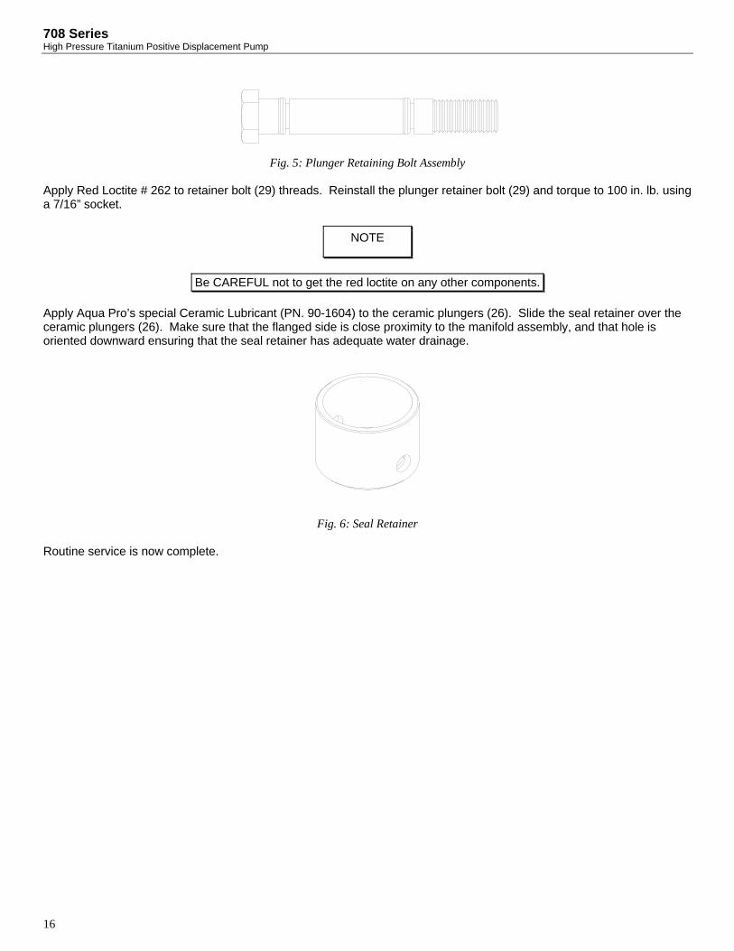
708 Series High Pressure Titanium Positive Displacement Pump
16
Fig. 5: Plunger Retaining Bolt Assembly
Apply Red Loctite # 262 to retainer bolt (29) threads. Reinstall the plunger retainer bolt (29) and torque to 100 in. lb. using a 7/16” socket.
Apply Aqua Pro’s special Ceramic Lubricant (PN. 90-1604) to the ceramic plungers (26). Slide the seal retainer over the ceramic plungers (26). Make sure that the flanged side is close proximity to the manifold assembly, and that hole is oriented downward ensuring that the seal retainer has adequate water drainage.
Fig. 6: Seal Retainer Routine service is now complete.
NOTE
Be CAREFUL not to get the red loctite on any other components.

17
SERVICING THE CRANKCASE The following are the procedures for servicing the crankcase assembly using the 708-1 Crankcase Rebuild Kit (PN. 70-6113). 708-3 Crankcase Rebuild Kit (PN. 70-6112). 708-5 Crankcase Rebuild Kit (PN. 70-6107). The manifold assembly must be detached from the crankcase to do the following service.
OIL DRAIN PLUG O-RING REPLACEMENT You will need these tools and parts to do the following:
7/8” Socket/ Socket Wrench Pick O-Ring, Drain Plug (4): PN. 30-1286 Anti-Seize Lubricant: PN. 85-0094 Silicon Grease Lubricant: PN. 21-1122
Remove the oil drain plug with a 7/8” wrench and drain the crankcase oil. Clean the drain plug (5), remove the o-ring (4) with the aide of the pick if necessary. Replace with the new one supplied in the kit. Apply anti-seize lube to the threads of the drain plug (5) and reinstall.
PLUNGER ROD SEAL REPLACEMENT You will need these tools and parts to do the following:
7/16” Socket/ Socket Wrench Torque Wrench Seal, Oil, Plunger Rod (7): PN. 70-6018 Washer, Plunger Retainer (27): PN. 70-6035 O-Ring, Plunger Retainer (26): PN. 70-6012 Slinger Barrier (24): PN. 70-6015 Ceramic Lubricant: PN. 85-0087 Silicone Grease Lubricant: PN. 21-1122 Red Loctite # 262 Lint-free Cloths
Remove the seal retainer (29) and set aside. Remove the plunger retainer bolt (28) with a 7/16” wrench, set aside. Remove the plunger retainer washer (28) and remove the ceramic plunger (26). Remove the slinger (25) and the outer washer (6). With the aide of the pick remove the plunger rod oil seal (7) from the crankcase. Inspect the seal retainer washers (8) for damage, if none evident then reuse, if damage is evident consult the factory.
Insert new plunger rod oil seal (7) into crankcase making sure that the seal is fully seated, place outer washer (6) on seal. Place slinger (25) onto the plunger rod (9).
NOTE
A light coating of silicon grease (PN. 21-1122) should be used on all new o-rings and seals. Use of any other type of grease may result in o-ring or seal failure.

708 Series High Pressure Titanium Positive Displacement Pump
18
Slide ceramic plungers (26) onto plunger rod and insert the plunger retainer washer (28) into the plunger. Clean the plunger retaining bolts (29). With the aide of a pick, remove the plunger retainer o-ring (27). Replace the o-ring (27) with the new one supplied in the kit as shown in Fig. 6. Slide the plunger retaining washer (28) onto the plunger retainer (29).
Fig. 5: Plunger Retaining Bolt Assembly Apply Red Loctite # 262 to retainer bolt (29) threads. Reinstall the plunger retainer bolt (29) and torque to 100 in. lb. using a 7/16” socket.
Apply Aqua Pro’s special Ceramic Lubricant (PN. 90-1604) to the ceramic plungers (26). Slide the seal retainer over the ceramic plungers (26). Make sure that the flanged side is close proximity to the manifold assembly, and that hole is oriented downward ensuring that the seal retainer has adequate water drainage.
Fig. 6: Seal Retainer
BEARING SIDE PLATE O-RING/SEAL REPLACEMENT You will need these tools and parts to do the following:
3/16" Allen Wrench Philips Head Screw Driver
NOTE
Examine the ceramic plungers (26) for cracks, heavy scoring, or unusual wear. If there is a problem, contact your dealer.
NOTE
Be CAREFUL not to get the red loctite on any other components.

19
Pick Seal, Oil, Crankshaft (18): PN. 70-6038 (708-1, 708-3) 70-6061 (708-5) O-Ring, Bearing Side Plate (15): PN. 70-6039 O-Ring, Sight Glass (22): 70-6082 Silicon Grease Lubricant: PN. 21-1122 Anti-Seize Lubricant: PN. 85-0094
Remove the 4 socket head cap screws (19) with a 3/16” Allen Wrench from each of bearing side plate (16), (17), this applies to the 708-1, 708-3 3.5 GPM, and the 708-5 pumps. With the aide of a pick remove the o-rings from the grooves, remove the crankshaft oil seal (18) from the pulley side bearing cap (17). For 708-3 2.3 GPM pumps with direct drive, uncouple the pump from the motor. Remove the 4 Philips head screws (36) holding the bell housing (34) to the pump. Now remove the bearing side plate (17), o-rings and seal can now be replaced. Remove the sight glass retainer (24) from the bearing side plate (16). With the aide of a pick remove the sight glass o-ring (22). Replace o-ring with the one provided in the kit.
Press new crankshaft oil seal (18) into pulley side bearing cap (17), Install o-ring (15) in o-ring groove on the crankshaft bearing caps (16), (17) and reinstall caps on pump.
Install the 4 socket head cap screws (19) onto each of the bearing side plates and tighten with a 1/4” Allen Wrench. This applies to the 708-1, 708-3 3.5 GPM, and the 708-5 pumps. For the 708-3 2.3 GPM pump, reinstall the bell housing (34) by installing the 4 Philips head screws (36).
CRANKCASE COVER O-RING REPLACEMENT In this procedure you will replace the o-rings on the crankcase cover as provided in the rebuild kit. You will need these tools and parts to do the following:
3/16” Allen Wrench Phillips Head Screwdriver Pick Silicone Grease Lubricant: PN. 21-1122 Red Loctite # 262 Anti-Seize Lubricant: PN. 85-0094
CAUTION
Crankshaft oil seal is press fit at the factory, care is to be exercised during removal so damage does not occur to sealing surface.
NOTE
A light coating of silicon grease (PN. 21-1122) should be used on all new o-rings and seals. Use of any other type of grease may result in o-ring or seal failure.
NOTE
A light coating of Anti-Seize Lubricant (PN. 85-0094) should be applied on all threaded parts, unless otherwise stated.

708 Series High Pressure Titanium Positive Displacement Pump
20
Unscrew the crankcase cover screws (19) with the 3/16” Allen wrench. With the aide of the pick remove the crankcase cover o-ring (20).
Install the new crankcase cover o-ring (20) provided with the rebuild kit.
Reinstall the crankcase cover and tighten the crankcase cover screws (19) with the 3/16” Allen wrench.
CRANKSHAFT BEARING, CONNECTING ROD-PISTON ASSEMBLY SERVICE It is recommended that any service to the crankshaft bearings (16) or to the connecting rod-piston assembly be done by the factory. Due to the high precision required only factory trained personnel are recommended for this service. Performing any maintenance other than rebuild and service kits voids the warranty if not performed by factory trained personnel.
SERVICING THE MANIFOLD The following are the procedures for servicing the crankcase assembly using the 708-1 Manifold Rebuild Kit (PN. 70-6079). 708-3 2.3 GPM Manifold Rebuild Kit (PN. 70-6110). 708-3 3.5 GPM Manifold Rebuild Kit (PN. 70-6111). 708-5 Manifold Rebuild Kit (PN. 70-6105). 8 GPM Pump Manufactured After Feb 2002 708-5 Manifold Rebuild Kit (PN. 70-6108). 7 GPM Pump Manufactured Before Aug 2002 The manifold assembly must be detached from the crankcase to do the following service.
NOTE
A light coating of silicon grease (PN. 21-1122) should be used on all new o-rings and seals. Use of any other type of grease may result in o-ring or seal failure.
NOTE
A light coating of Anti-Seize Lubricant (PN. 85-0094) should be applied on all threaded parts, unless otherwise stated.

21
Fig. 7: Manifold Assembly
INLET/DISCHARGE ADAPTER O-RING REPLACEMENT 708-3 & 708-5 You will need these tools and parts to do the following:
3/4” Socket/ Socket Wrench Pick O-Ring, Discharge Plug Adapter (48): PN. 30-1286 Silicone Grease Lubricant: PN. 21-1122 Anti-Seize Lubricant: PN. 85-0094
Remove the Discharge/Plug (50) and (49) adapters from the manifold assembly with the 3/4” Socket/ Socket Wrench. With the aide of a pick remove the o-rings (48) from each of the adapters.
Install the new o-rings (48) provided with the kit onto each of the adapters.
Reinstall each of the adapters onto the manifold assembly, tighten adapter with 3/4” Socket/ Socket Wrench.
VALVE ASSEMBLY SERVICING You will need these tools and parts to do the following:
7/8" Socket Wrench or Combination Wrench Pick
NOTE
A light coating of silicon grease (PN. 21-1122) should be used on all new o-rings and seals. Use of any other type of grease may result in o-ring or seal failure.
NOTE
A light coating of Anti-Seize Lubricant (PN. 85-0094) should be applied on all threaded parts, unless otherwise stated.
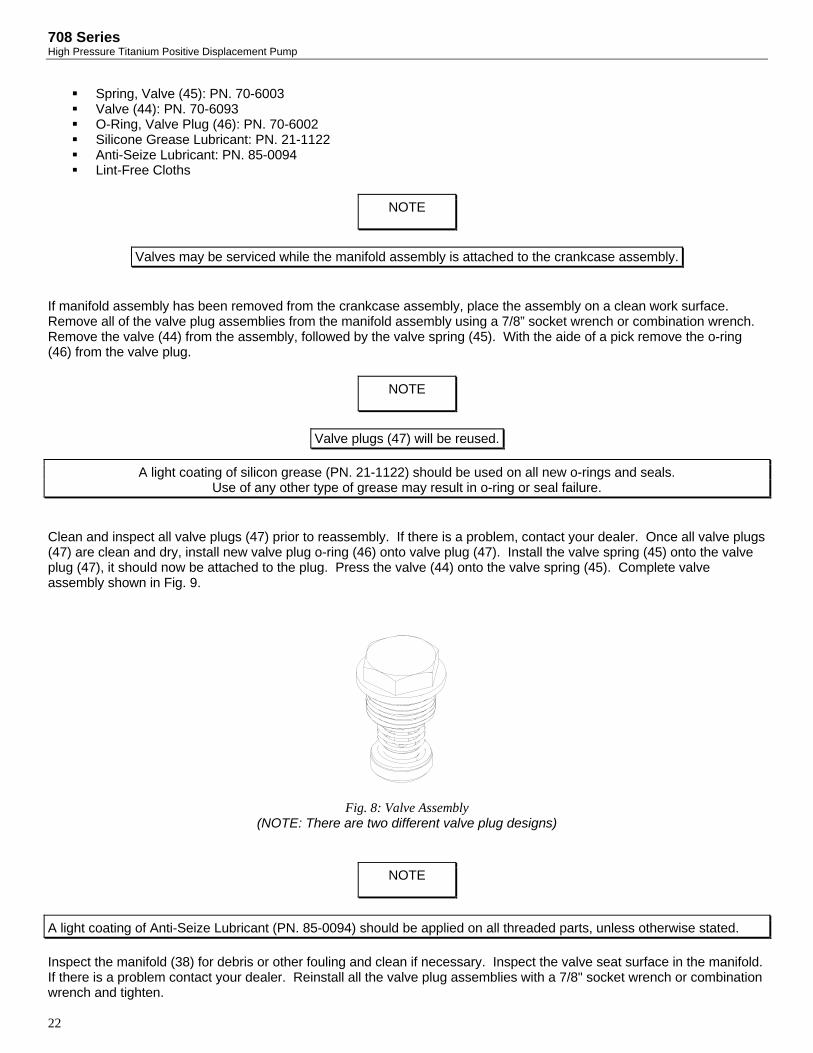
708 Series High Pressure Titanium Positive Displacement Pump
22
Spring, Valve (45): PN. 70-6003 Valve (44): PN. 70-6093 O-Ring, Valve Plug (46): PN. 70-6002 Silicone Grease Lubricant: PN. 21-1122 Anti-Seize Lubricant: PN. 85-0094 Lint-Free Cloths
If manifold assembly has been removed from the crankcase assembly, place the assembly on a clean work surface. Remove all of the valve plug assemblies from the manifold assembly using a 7/8” socket wrench or combination wrench. Remove the valve (44) from the assembly, followed by the valve spring (45). With the aide of a pick remove the o-ring (46) from the valve plug.
Clean and inspect all valve plugs (47) prior to reassembly. If there is a problem, contact your dealer. Once all valve plugs (47) are clean and dry, install new valve plug o-ring (46) onto valve plug (47). Install the valve spring (45) onto the valve plug (47), it should now be attached to the plug. Press the valve (44) onto the valve spring (45). Complete valve assembly shown in Fig. 9.
Fig. 8: Valve Assembly
(NOTE: There are two different valve plug designs)
Inspect the manifold (38) for debris or other fouling and clean if necessary. Inspect the valve seat surface in the manifold. If there is a problem contact your dealer. Reinstall all the valve plug assemblies with a 7/8" socket wrench or combination wrench and tighten.
NOTE
Valves may be serviced while the manifold assembly is attached to the crankcase assembly.
NOTE
Valve plugs (47) will be reused.
A light coating of silicon grease (PN. 21-1122) should be used on all new o-rings and seals. Use of any other type of grease may result in o-ring or seal failure.
NOTE
A light coating of Anti-Seize Lubricant (PN. 85-0094) should be applied on all threaded parts, unless otherwise stated.

23
MANIFOLD SEAL SERVICING
You will need these tools and parts to do the following:
Snap Ring Pliers Tool, Weep Ring Puller, 708 Series: PN. 91-3827 Flat screw driver Seal, HP (40): PN. 70-0071 Ring, Snap (42): PN. 70-6010 Assembly, Weep Ring (41): PN. 70-3018 Seal, LP (43): PN. 70-6009 Silicone Grease Lubricant: PN. 21-1122 Lint-Free Cloths
For manifold seal servicing purposes the manifold must be placed with the valve plugs sitting on a flat surface and the plunger bores facing upward. This will facilitate service technician access to the seals for removal and installation, as shown in Fig. 10.
Fig. 9: Orientation for Manifold Seal Servicing With a flat screw driver remove the low-pressure seal (43). Manually remove the low-pressure seal spacer (39). With the snap ring pliers remove the snap ring (42). Using the weep ring extracting tool remove the weep ring assembly (41) as shown in Fig. 11.
NOTE
Pump manifold assembly must be detached from the crankcase assembly to service the seals.
NOTE
Extraction of the rings is accomplished by inserting tool in relaxed state into the inner diameter of the rings, then tighten the expansion bolt to grip the ring. Install the extraction stand and nut, tightening nut will extract to weep ring and isolating ring from manifold.

708 Series High Pressure Titanium Positive Displacement Pump
24
Fig. 10: Weep Ring Extraction With a flat screwdriver remove the high-pressure seals (40). Manually remove the high-pressure seal spacer (40). You must clean and inspect the following parts for re-use:
• Spacer, High-Pressure Seal (39): PN. 70-6016 • Spacer, Low-Pressure Seal (39): PN. 70-6016
Insert the high-pressure seal spacer (39) into the bore.
Insert the high-pressure seal (40) into the bore until the seal is fully seated on the high-pressure seal spacer (39). Insert the weep ring (41) into the bore after the installation of the high-pressure seals (39). Install the snap ring (42) using the snap ring pliers.
Insert the low-pressure seal spacer (39) and press in the new low-pressure seal (43). The manifold seal servicing is complete.
ATTACHING THE MANIFOLD TO THE CRANKCASE You will need these tools and parts to do the following:
9/16” Socket/ Socket Wrench (for 708-5) 1/2” Socket/ Socket Wrench (for 708-3) 3/16” Allen Wrench (for 708-1) Dead Blow Hammer Dead Blow Hammer Manifold Bolt (58): PN. 70-6055 (for 708-5) Manifold Bolt (58): PN. 70-6008 (for 708-3) Manifold Screw (58): PN. 70-6046 (for 708-1) Ceramic Lubricant: PN. 85-0087 Anti-Seize Lubricant: PN. 85-0094
NOTE
A light coating of silicon grease (PN. 21-1122) should be used on all new o-rings and seals. Use of any other type of grease may result in o-ring or seal failure.
NOTE
Ensure that the snap ring (42) is fully seated in the snap ring groove before continuing.

25
If a crankcase seal rebuild was not performed at this time then ensure that the dowel locating pins (53) are pressed into their corresponding hole. Ensure that ceramic lubricant is applied to the ceramic plunger assemblies and that the seal retainers are installed with the flange located away from the crankcase assembly.
Align manifold assembly to crankcase assembly and tighten the two manifold bolts (58) with a 9/16” socket wrench for the 708-5, with a 1/2” socket wrench for the 708-3, or the 4 socket head bolts with the 3/16” Allen wrench for the 708-1.
NOTE
A light coating of Anti-Seize Lubricant (PN. 85-0094) should be applied on all threaded parts, unless otherwise stated.

708 Series High Pressure Titanium Positive Displacement Pump
26

708-1 DRAWINGS
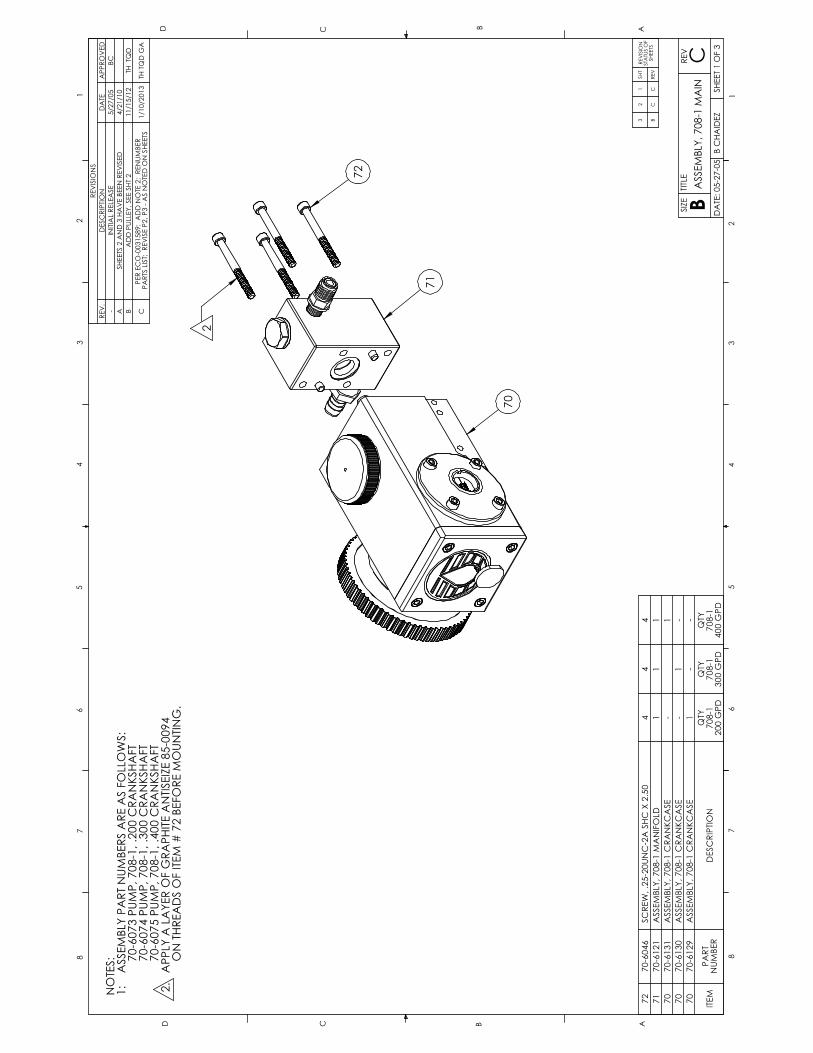
ABCD
12
67
887
65
43
21
SIZE
BTITLE
REV
B CHAIDEZ
DATE: 05-27-05
CSHEET 1 OF 3
ASSEMBLY, 708-1 M
AIN
54
D C B A
3
70
SHEETS 2 AND 3 HAVE BEEN REVISED
ADD PULLEY, SEE SHT 2
B
PER ECO-0031589: ADD NOTE 2; RENUMBER
ASSEMBLY, 708-1 M
ANIFOLD
1
C
TH TQD
-1
-ASSEMBLY, 708-1 CRANKCASE
TH TQD GA
1/10/2013
170-6129
--
ASSEMBLY, 708-1 CRANKCASE
11/15/12
PARTS LIST; REVISE P2, P3 - AS NOTED ON SHEETS
4/21/10
11
70
70-6131
ASSEMBLY, 708-1 CRANKCASE
-1
70
70-6130
ITEM
PART
NUMBER
DESCRIPTION
QTY
708-1
200 GPD
QTY
708-1
300 GPD
QTY
708-1
400 GPD
72
70-6046
SCREW, .25-20UNC-2A SHC X 2.50
44
4
71
70-6121
REVISIONS
REV.
DESCRIPTION
DATE
APPROVED
-INITIAL RELEASE
5/27/05
BC
A
32
1SHT
REVISION
STATUS OF
SHEETS
BC
CREV
72
71
70
2
NOTES:
1: ASSEMBLY PART NUMBERS ARE AS FOLLOWS:
70-6073 PUMP, 708-1, .200 CRANKSHAFT
70-6074 PUMP, 708-1, .300 CRANKSHAFT
70-6075 PUMP, 708-1, .400 CRANKSHAFT
2. APPLY A LAYER OF GRAPHITE ANTISEIZE 85-0094
ON THREADS OF ITEM # 72 BEFORE M
OUNTING.

37
39
39
39
39
39
37
12X TORQUE
3
10
14
54
21
20
34
19
17
18
15
31
26
2
13
87
6
25
27
30
28
29
16
22
23
24
9
11
1
27
32
33
TO 50 IN-LBS
TO 95 IN-LBS
2X TORQUE
TORQUE TO
55 IN-LBS
ABCD
12
67
887
65
4
B CHAIDEZ
21
SIZE
3
TITLE
4
BDATE: 05-26-05
CREV
ASSEMBLY, 708-1 CRANKCASE
5
SHEET 2 OF 3
D C B A
3
11
1-
170-6045
CRANKCASE,708-1,AL
11
1-
-
370-6030
CAP, OIL FILLER, PUMP, 708 SERIES
11
1-
-
270-6029
O-RING, OIL FILLER CAP
1
DENOTES THE OFFSET OF THE CRANKSHAFT STROKE. SEE DESCRIPTION FOR ITEM (12).
4) PUMP CRANKSHAFTS ARE STAMPED WITH A NUMBER 2, 3, OR 4 ON THE END THIS
70-6128 ASSY, DRIVE , 708 SERIES PUMPS
3) ITEMS 9,10 AND 11 MAY BE PURCHASE UNDER THE FOLLOWING PART NUMBER:
2) PART NUMBER 85-0087 AND 21-1122 ARE NOT SHOWN IN DRAWING
70-6181 KIT, ROUTINE SERVICE, 708-1
70-6113 KIT, REBUILD, CRANKCASE, 708-1
70-6131 ASSY, CRANKCASE, 708-1, .400 CRANKSHAFT
70-6130 ASSY, CRANKCASE, 708-1, .300 CRANKSHAFT
70-6129 ASSY, CRANKCASE, 708-1, .200 CRANKSHAFT
1) ASSEMBLY PART NUMBERS ARE AS FOLLOWS:
NOTES:
ITEM
PART
NUMBER
DESCRIPTION
QTY .200
STROKE
(70-6129)
QTY .300
STROKE
(70-6130)
QTY .400
STROKE
(70-6131)
QTY
REBUILD
KIT
(70-6113)
QTY
SERVICE
KIT
(70-6181)
39
21-1122
SILICONE GREASE
--
--
1
38
85-0087
ANTISIEZE, NM.91
--
-1
1
37
90-0225
LOCKTITE 262, THREAD LOCKER
AR
AR
AR
--
36
-NOT USED
--
--
-
35
-NOT USED
--
--
-
34
70-6050
CRANKSHAFT,708-1,.200
1-
--
-
33
70-0597
PULLEY
11
1-
-
32
70-0031
SPACER,CRANKSHAFT,708-1
22
2-
-
31
30-1106
PLUG, CRANKCASE
22
2-
-
30
70-6014
RETAINER,SEAL,708-1/3 SERIES
11
11
-
29
70-6035
WASHER, PLUNGER RETAINER, 708 SERIES
1-
28
70-6011
BOLT, PLUNGER RETAINER, 708 SERIES
11
1-
-
27
70-6012
O-RING, PLUNGER RETAINER
22
22
-
26
70-6013
PLUNGER, 708 SERIES
11
1-
-
25
70-6015
SLINGER, PLUNGER, 708 SERIES
11
1-
-
24
70-6043
RETAINER, SIGHTGLASS
11
1-
-
23
70-6044
SIGHTGLASS, OIL
11
1-
-
22
70-6082
O-RING, OIL SIGHTGLASS
11
11
-
21
70-6049
COVER, CRANKCASE, 708-1
11
1-
-
20
70-6048
O-RING, REAR COVER, 708-1
11
11
-
19
86-0151
CAPSCREW, SKT HD, .25-20UNC-2A, .75, 316 CRES
12
12
12
--
18
70-6038
SEAL, OIL, CRANKSHAFT, 708-1/3
11
11
-
17
70-6041
CAP, PULLEY BEARING, 708 SERIES
11
1-
-
16
70-6042
CAP, GUIDE BEARING, 708 SERIES
11
1-
-
15
70-6039
O-RING, BEARING CAP
22
22
-
14
70-6037
BEARING, CRANKSHAFT, 708-1/3
22
2-
-
13
70-1281
RING, SNAP, 708 SERIES
22
2-
-
12
70-6052
CRANKSHAFT, 708-1, 29 GPH (.4" STROKE)
--
1-
-
12
70-6051
CRANKSHAFT, 708-1, 22 GPH (.3" STROKE)
-1
--
-
11
70-6033
ASSY, CONNECTING ROD, 708 SERIES
11
1-
-
10
70-0382
PIN, DOWEL, M9, 22, STL
1
970-6067
PLUNGER, 708 SERIES
11
1-
-
870-6019
WASHER, OIL SEAL, INNER, 708 SERIES
11
1-
-
770-6018
SEAL, OIL, 708 SERIES
11
11
1
670-6017
WASHER, OIL SEAL, OUTER, 708 SERIES
11
1-
-
570-0696
PLUG, MS18829-08
11
1-
-
430-1286
O-RING, PLUG, OIL DRAIN
11
11
-
REVISIONS
REV.
DESCRIPTION
DATE
APPROVED
-INITIAL RELEASE
5/26/05
BC
AMODIFIED BOM QTY TITLE, NOTE INCLUDES ITEMS NOT IN
BOM TABLE
3/26/10
CC
BADD ITEM 32 & 33, PART 34 WAS PART 37
ADD PART 33 TO SHEET 2
11/15/12
TH TQD
CPER ECO-0031589: ADD ITEM 37 - THREAD LOCKER:
ADD ITEMS 37 & 39 BALLOONS; ADD: TORQUES
1/10/13TH TQD GA

56
50
57
57
55
59
5153
54
51
63
58
60
62
55
52
56
4
58
54
D C B AABCD
12
67
887
65
43
21
SIZE
BTITLE
REV
B CHAIDEZ
DATE: 05-27-05
BSHEET 3 OF 3
ASSEMBLY, 708-1 MANIFOLD
3
RING, SPACER, SEAL, 708 SERIES
70-6016
51
-1
NOTES:
70-6181 KIT, SERVICE KIT, 708-1
1) ASSEMBLY PART NUMBERS ARE AS FOLLOWS:
2
70-6079 KIT, REBUILD, MANIFOLD, 708-1
1SEAL, HP, 708 SERIES
--
3 APPLY A THIN LAYER OF SILICONE GREASE ITEM 65 (21-0022) TO ALL O-RINGS.
4 APPLY A LAYER OF GRAPHITE ANTISEIZE ITEM 64 (OR P/N 90-0928) TO
ALL CONTACT THREADS OF ITEMS 58 & 60 BEFORE MOUNTING.
4
3
70-6121 ASSY, MANIFOLD, 708-1
50
70-6047
MANIFOLD, 708-1
1
4
-
3
PART NO. 8500087 AND 21-0022 ARE NOT SHOWN IN DRAWING.
2)
70-0071
2
ITEM
PART NUMBER
DESCRIPTION
QTY
(70-6121)
QTY
REBUILD
KIT
(70-6079)
QTY
SERVICE
KIT
(70-6181)
65
21-1122
SILICONE GREASE
-1
1
64
85-0094
ANTISIEZE, GRAPHITE, FOOD GRADE
--
1
63
70-3018
ASSY, WEEP RING, 708 SERIES
11
-
62
30-0453
ADAPTER, LP INLET, 708-1
1-
-
60
30-0946
ADAPTER, HP DISCHARGE, 708-1
1-
-
59
70-6087
PIN, MANIFOLD, 708 SERIES
2-
-
58
70-6001
PLUG,VALVE,STANDARD,708 SERIES
2-
-
57
70-6002
O-RING, OIL DRAIN/VALVE PLUG
22
2
56
70-6003
SPRING, VALVE, 708 SERIES
22
2
55
70-6093
VALVE, 708 SERIES
22
2
54
70-6009
SEAL, LP, 708 SERIES
11
1
53
70-6010
RING, SNAP, 708 SERIES
11
-
52
REVISIONS
REV.
DESCRIPTION
DATE
APPROVED
-INITIAL RELEASE
5/27/05
BC
AMODIFIED BOM QTY TITLE, NOTE INCLUDES ITEMS NOT IN BOM TABLE
3/26/10
CC
BPER ECO-0031589: DEL: NOTE 2; ADD: NOTES 3,4; RENUMBER P/LIST.
1/10/13
GH TQD GA

AquaPro® Sea WaterRO Membranes
AquaPro® thin film composite reverse osmosis membranes deliver high salt rejection while maintaining high production rates to obtain the energy efficiency demanded by plant operators.
By selecting the highest grade of materials and thoroughly testing
performance, Racor Village Marine is able to offer the highest quality products.
Aqua Pro® membranes are designed for use in Racor Village Marine pressure vessel housings as well as other brand housings.
Contact Information:Parker Hannifin CorporationFiltration Group-Parker Village Marine2630 E. El Presidio StreetCarson, CA 90810
Toll free: 1800 C-ParkerPhone: 310 608 5600Fax: 310 608 5692Email sales:[email protected] support:[email protected]/watermakers

• Maximum Operating Pressure: 1000 psi
• Maximum Operating Temperature: 113°F (45°C)
• Maximum Feed Turbidity: 1 NTU• Free Chlorine Tolerance: 0 PPM
• Maximum Feed Silt Density Index: SDI 5
• pH Range: Continuous Operation: 4-11 Short-term for Cleaning: (30 minute duration) 2.5-11
AquaPro®
Sea Water RO Membranes
Notes:
RecommendedOperating Limits:
A
BTYP
CD15°
• Keep elements moist at all times
• Permeate obtained from first two hours of operation should be discarded
• To prevent biological growth during storage, shipping, or system shutdowns it is recommended that elements be immersed in a protective solution. The standard solution for long or short term storage should contain 1.0 percent (by weight) sodium metabisulfite (available as VMT p/n 85-0103, 85-0038, 85-0044 or 85-0049)
• Standardized test conditions are 32,000 ppm NaCl at 77° F (25° C), with 800 psi feed. Production rates for individual elements may vary +/- 20% and rejection may vary +/- 0.4%
* All 19” and 38” elements come with a 2” removable extender so that the stocked size also fits 21” and 40” housings** Elements are specially designed for low feed flow applications. Use only with certain Sea Quencher and Little Wonder watermakers.
Print Reorder Number 7897 Rev-C 02-17-2016© 2016 Parker Hannifin Corporation
To maintain peak performance always use genuine Parker-Racor/Village Marine Tec. replacement parts.We reserve the right to change our specifications or standards without notice.
Nominal Size
25192519251925382538404060408040
Product FlowGPD m3/day
220 - 0.83150 - 0.57105 - 0.40550 - 2.08210 - 0.80
1200 - 4.542500 - 9.477250-27.36
Typical SaltRejection %
99.499.099.099.499.099.499.499.4
VMTPart No.
33-251933-3000 **33-3001**33-0238
33-3002**33-044033-003633-0840
Dimensionsinches/cm
A*19/4819/4819/48
38/96.538/96.540/101.640/101.640/101.6
B1.1/2.81.1/2.81.1/2.81.1/2.81.1/2.81.0/2.51.27/3.2
0
C0.75/1.90.75/1.90.75/1.9 0.75/1.90.75/1.90.75/1.91.5/3.8
1.125/29
D2.4/6.12.4/6.12.4/6.12.4/6.12.4/6.1
3.96/10.15.98/15.27.9/201

Parker Village Marine RO membrane pressure vessels feature non-metallic wetted surfaces for excellent corrosion resistance.Simple end plug design allows quick removal for element servicing.If the size you require is not shown please contact us for custom builds.
Pressure Vessel Assemblies
Key Features:• Operating Pressure:
1000 psi/68 bar• Shell: Filament Wound fiberglass• Collars: 6061 T-6 Powdercoated
aluminum• End Plugs: Thermoplastic• End Ring:
6061 T-6 Anodized aluminum on 2.5” and 4” sizeSS316 on 6” size
• Fasteners: SS316
For Seawater Elements
Contact Information:Parker Hannifin CorporationFiltration Group-Parker Village Marine2630 E. El Presidio StreetCarson, CA 90810
Toll free: 1800 C-ParkerPhone: 310 608 5600Fax: 310 608 5692Email sales:[email protected] support:[email protected]/watermakers

Description
Vessel Assembly**
Product O-ring
End Plug O-ring
End Plug
End Ring
Capscrews
Shell White Gray
Item
1
2
3
4
5
6
7
Quantity per Assembly
4
2
2
2
***
11
2.5” x 19”
32-2519
32-2116
32-2228
32-2513*
32-4013
86-0106
32-002532-0098
5/2
2.5” x 38”
32-2537*
32-2116
32-2228
32-2513*
32-4013
86-0106
32-002632-0099
7/3
4” x 40”
32-0444
32-2116
32-4342
32-4012
32-4014
86-0123
Please Call32-4001
22/10
6” x 40”
32-6040
32-2229
32-0640
32-6012
32-0096
86-0136
Please Call32-0001
45/20Weight (lbs/kg)
Notes:
*End Plug 32-2517 is also available for 2.5” vessels, which offers straight, coarse thread feed/reject port used on some VMT PW watermakers. Use of coarse thread end plug changes the vessel assembly p/n to 32-2538
*** Capscrews: Order 6 per end plug on 2.5” sizeOrder 8 per end plug on 4” sizeOrder 10 per en plug on 6” size
Pressure Vessel AssembliesFor Seawater Elements
Part Numbers:
1
2 3 4 5 67
Print Reorder Number 7898 Rev-B 02-17-2016© 2016 Parker Hannifin Corporation
To maintain peak performance always use genuine Parker-Racor/Village Marine Tec. replacement parts.We reserve the right to change our specifications or standards without notice.
**Membrane not included.For applicable membrane elements see bulletin No. 7897 (Aqua Pro RO Membranes)

The Village Marine Tec. line of pleated filters are designed specifically for the RO watermaker industry and are superior to wound or polyspun cartridges to give you a longer filter life as well as increasing flow rates and keeping cartridge size down.
Available in a wide arrange of sizes and micron ranges to ensure that every type of watermaker filter need is taken care of. Stock sizes fit most standard filter housings, if the size you need is not shown please contact us with the dimensions required.
Pleated Filters and Filter Cartridge Kits
Single use Cleaning and Preservative Cartridge Kits are designed specifically for small RO Systems. The Cartridges allow for easy and effective membrane maintenance.
The Cleaning and Preservative Cartridge Kits eliminate the trouble and mess of measuring powdered chemicals and ensuring correct chemical concentrations. The Chemical cartridges fit directly into 2.5” x 10” or 4.5” x 10” housings and contain the correct amount of chemical for a single use.
Contact Information:Parker Hannifin CorporationFiltration Group-Parker Village Marine2630 E. El Presidio StreetCarson, CA 90810
Toll free: 1800 C-ParkerPhone: 310 608 5600Fax: 310 608 5692Email sales:[email protected] support:[email protected]/watermakers
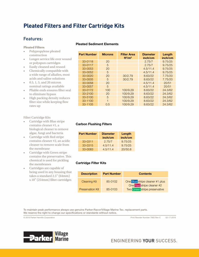
Pleated Filters• Polypropylene pleated
construction• Longer service life over wound
or polyspun cartridges• Easily cleaned and reused• Chemically compatible with
a wide range of alkalies, most acids and saline solutions
• 0.5, 1, 5, and 20 micron nominal ratings available
• Pliable ends ensures filter seal to eliminate bypass
• High packing density reduces filter size while keeping flow rates up
Filter Cartridge Kits• Cartridge with Blue stripe
contains cleaner #1, a biological cleaner to remove algae, fungi and bacteria
• Cartridge with Red stripe contains cleaner #2, an acidic cleaner to remove scale from the membrane
• Cartridge with Green stripe contains the preservative. This chemical is used for pickling the membranes
• Cartridges are capable of being used in any housing that takes a standard 2.5” (64mm) x 10” (254mm) filter cartridges
Pleated Filters and Filter Cartridge Kits
Features:
Carbon Flushing Filters
Cartridge Filter Kits
Pleated Sediment Elements
Part Number
33-011833-011733-005333-005233-002033-000533-005833-005733-017233-210033-510033-110033-1105
Microns
205
205
205
205
1002051
0.5
Filter Areaft2/m2
30/2.7930/2.79
100/9.29 100/9.29100/9.29100/9.29100/9.29
Diameterinch/cm2.75/72.75/7
4.5/11.44.5/11.48.63/228.63/224.5/11.44.5/11.48.63/22 8.63/228.63/228.63/228.63/22
Lengthinch/cm9.75/259.75/259.75/259.75/257.75/207.75/2020/5120/51
24.3/62 24.3/6224.3/6224.3/6224.3/62
Diameterinch/cm2.75/7
4.5/11.44.5/11.4
Lengthinch/cm9.75/259.75/2520/50.8
Part Number
33-031133-031533-0083
Part Number
85-0102
85-0103
Description
Cleaning Kit
Preservation Kit
Contents
One Blue stripe cleaner #1 plusOne Red stripe cleaner #2
Two Green stripe preservative
Print Reorder Number 7905 Rev-C 02-17-2016© 2016 Parker Hannifin Corporation
To maintain peak performance always use genuine Parker-Racor/Village Marine Tec. replacement parts.We reserve the right to change our specifications or standards without notice.