Embed Size (px)
Citation preview
THE IRON HORSEA CONCISE ILLUSTRATED
HISTORY OF THE DEVELOPMENT OFSTEAM TRACTION
JOHN WALTER
First published in 2012 by
www.archivingindustry.com
with the assistance ofThe Canadian Museum of Making
copyright © John Walter, 2008, 2012
The right of John Walter to be identified as the author of this work has been asserted by him in accordance with the Copyright, Designs and Patents Act of 1988.
All rights reservedNo part of this publication may be reproduced, stored in or introduced into a
retrieval system, or transmitted, in any form or by any means (electronic, mechanical,photocopying, recording or otherwise), without the prior written permission of
the author and the publisher.
PRODUCED BY JOHN WALTER
T H E D E V E LO P M E N T O F S T E A M T R A C T I O N O N T H E R A I LWAY
PA G E 5
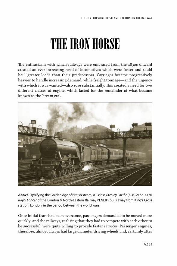
The enthusiasm with which railways were embraced from the 1830s onward created an ever-increasing need of locomotives which were faster and could haul greater loads than their predecessors. Carriages became progressively heavier to handle increasing demand, while freight tonnage—and the urgency with which it was wanted—also rose substantially. This created a need for two different classes of engine, which lasted for the remainder of what became known as the ‘steam era’.
Once initial fears had been overcome, passengers demanded to be moved more quickly; and the railways, realising that they had to compete with each other to be successful, were quite willing to provide faster services. Passenger engines, therefore, almost always had large diameter driving wheels and, certainly after
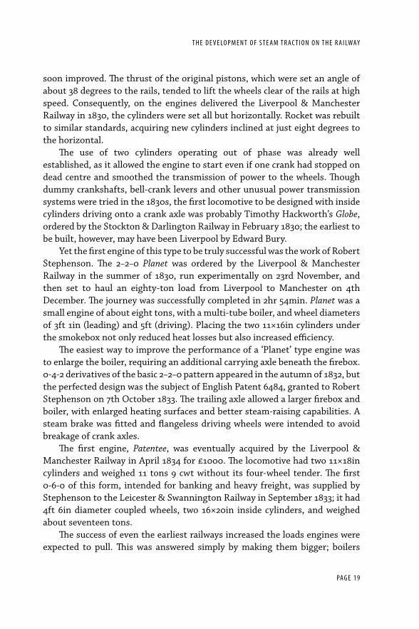
Above. Typifying the Golden Age of British steam, A1-class Gresley Pacific (4–6–2) no. 4476 Royal Lancer of the London & North-Eastern Railway (‘LNER’) pulls away from King’s Cross station, London, in the period between the world wars.
THE IRON HORSE

T H E I R O N H O R S E
PA G E 6
the 1850s, a leading bogie or swivelling single axle truck to allow curves to be taken at high speed. However, though the large wheel allowed a greater length of line to be covered for each stroke of the piston, the tractive force available for pulling a load was proportionately reduced. In addition, as only one or two driving axles were used, only a little more than half the engine weight was carried on the driving wheels. Called the ‘adhesion weight’, this showed whether the engine could start a heavy load away from a station and climb gradients reliably. Some passenger locomotives used on hilly routes had quite small wheels, but these were still usually accompanied by a leading bogie or truck.
The most important goal of a goods engine was to pull as much as possible. Speeds did not need to be high, so small wheels were fitted. These engines did not need bogies or trucks, so all of their weight could be carried on the driving wheels. Some railways settled on compromise designs, often where perishable freight had to be moved quickly (e.g., fruit, fish or refrigerated meat), but these engines rarely had more than a leading truck. The ‘mixed traffic’ engine only became popular during the twentieth century, combining medium diameter wheels with as many driving axles as possible.
At the beginning of the Railway Age, the gauge, or distance between the tracks, was not settled. Though many lines kept to the 4ft 8½in recommended by the Stephensons, gauges of 5ft 6in, 6ft or even 7ft were also used. The Great Western Railway Broad Gauge (7ft 0¼in) had considerable stability advantages over the 4ft 8½in gauge, but the lobbying power of the standard gauge railways prevailed and the last Broad Gauge lines were converted in 1892. However, the meagre dimensions of the standard gauge hamstrung British railway development in many ways—e.g., by restricting the dimensions of locomotive cylinders or the space allocated in passenger carriages.
As train loads grew progressively larger, the haulage ability of the railway locomotive was tested to its limit. The easiest method of increasing power was to enlarge the cylinders, extend the fire grate and lengthen the boiler. However, this increased engine weight considerably and increased the loading on each individual axle unless additional wheels were added. Thus the 2-4-0 two cylinder passenger engine evolved into a three or four cylinder 4-6-2 and ultimately to a 4-8-4; the 0-4-0 freight engine became an 0-6-0, an 0-8-0 and—eventually—a colossal 4-12-2. Freight engines invariably had two cylinders.
Among alternative solutions to the ever-increasing loads were higher working pressures, many differing types of compounding, extra cylinders, the introduction of enormous articulated engines weighing as much as 500 tons, and a prolonged investigation into thermal efficiency.
T H E D E V E LO P M E N T O F S T E A M T R A C T I O N O N T H E R A I LWAY
PA G E 7
Wheel arrangements
No attempt to summarise the history of the railway locomotive would be possible without an understanding of the conflicting systems of classification used to categorise them. In the English-speaking world, locomotives are now customarily classed in accordance with a system devised in 1900 by a clerk employed by the New York Central Railroad, Frederic Whyte (1865–1941). However, Whyte’s annotation sometimes makes it difficult to distinguish between driven and carrying wheels; or, alternatively, axles carried in bogies, trucks or rigidly in the frame.
At the time of its introduction in the USA, the Whyte classification was capable of satisfying virtually all ‘main line’ applications, as the period of experimentation—at least so far as North America was concerned—was almost over. In Europe, however, the situation was less clear; Fairlie, Mallet, Garratt and comparable articulated machines could usually be accommodated in the White scheme, but the oddities of railway history were often much more
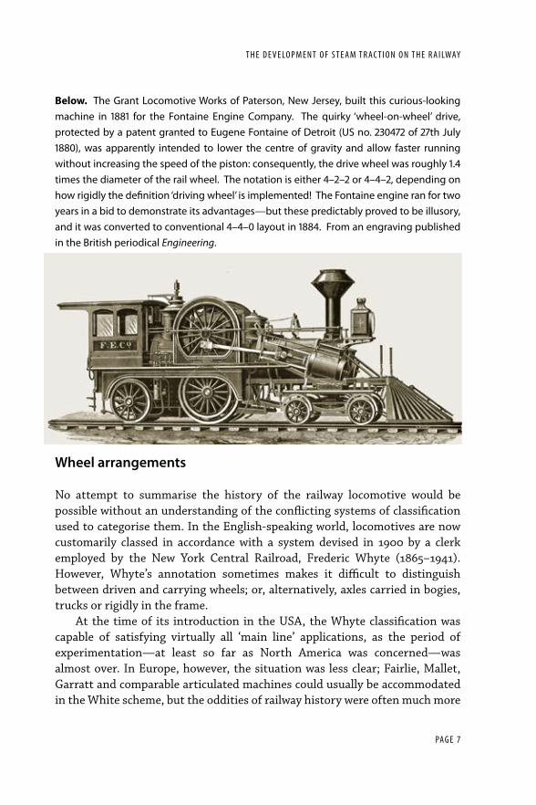
Below. The Grant Locomotive Works of Paterson, New Jersey, built this curious-looking machine in 1881 for the Fontaine Engine Company. The quirky ‘wheel-on-wheel’ drive, protected by a patent granted to Eugene Fontaine of Detroit (US no. 230472 of 27th July 1880), was apparently intended to lower the centre of gravity and allow faster running without increasing the speed of the piston: consequently, the drive wheel was roughly 1.4 times the diameter of the rail wheel. The notation is either 4–2–2 or 4–4–2, depending on how rigidly the definition ‘driving wheel’ is implemented! The Fontaine engine ran for two years in a bid to demonstrate its advantages—but these predictably proved to be illusory, and it was converted to conventional 4–4–0 layout in 1884. From an engraving published in the British periodical Engineering.
T H E I R O N H O R S E
PA G E 8
difficult to categorise. A system popular in Continental Europe, which counted the wheels per side instead of in total and uses letters to identify driven wheels, had great advantages. Unfortunately, it was rarely used in the Anglo-American world even though Oliver Bulleid of the Southern Railway tried to introduce it to Britain with his Merchant Navy class Pacifics (4-6-2 according to Whyte, or 2C1 to Bulleid).
A challenge to the Whyte system was also posed by locomotives such as the early Webb compounds running on the London & North Western Railway, which had axles driven independently. Had coupling rods been fitted, the locomotives would have been readily classifiable as 2-4-0, 2-4-2, 4-4-0 or 2-6-0. Owing to the quirky drive system, they are often classified as 2-2-2-0, 2-2-2-2, 4-2-2-0 and 2-2-4-0, but this does not give an immediate indication of the position of the driving wheels.
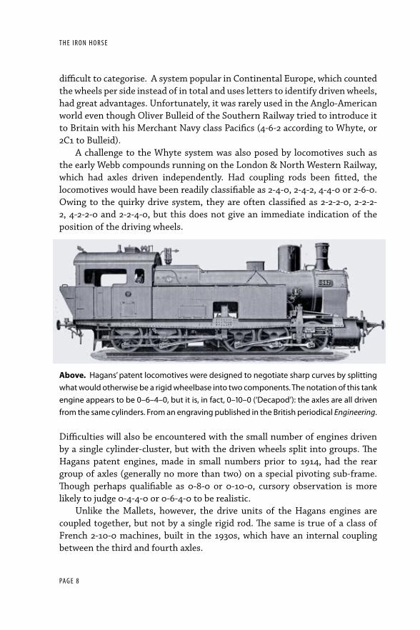
Difficulties will also be encountered with the small number of engines driven by a single cylinder-cluster, but with the driven wheels split into groups. The Hagans patent engines, made in small numbers prior to 1914, had the rear group of axles (generally no more than two) on a special pivoting sub-frame. Though perhaps qualifiable as 0-8-0 or 0-10-0, cursory observation is more likely to judge 0-4-4-0 or 0-6-4-0 to be realistic.
Unlike the Mallets, however, the drive units of the Hagans engines are coupled together, but not by a single rigid rod. The same is true of a class of French 2-10-0 machines, built in the 1930s, which have an internal coupling between the third and fourth axles.
Above. Hagans’ patent locomotives were designed to negotiate sharp curves by splitting what would otherwise be a rigid wheelbase into two components. The notation of this tank engine appears to be 0–6–4–0, but it is, in fact, 0–10–0 (‘Decapod’): the axles are all driven from the same cylinders. From an engraving published in the British periodical Engineering.
T H E D E V E LO P M E N T O F S T E A M T R A C T I O N O N T H E R A I LWAY
PA G E 9
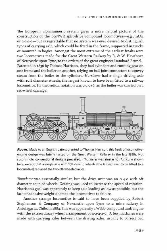
The European alphanumeric system gives a more helpful picture of the construction of the L&NWR split-drive compound locomotives—e.g., 1AA1 or 2-2-2-2—but is regrettable that no system was ever devised to distinguish types of carrying axle, which could be fixed in the frame, supported in trucks or mounted in bogies. Amongst the most extreme of the earliest freaks were two locomotives made for the Great Western Railway by R. & W. Hawthorn of Newcastle upon Tyne, to the orders of the great engineer Isambard Brunel.Patented in 1836 by Thomas Harrison, they had cylinders and running gear on one frame and the boiler on another, relying on ball-joint connectors to convey steam from the boiler to the cylinders. Hurricane had a single driving axle with 10ft diameter wheels, the largest known to have been fitted to a railway locomotive. Its theoretical notation was 2-2-2+6, as the boiler was carried on a six-wheel carriage.
Thunderer was essentially similar, but the drive unit was an 0-4-0 with 6ft diameter coupled wheels. Gearing was used to increase the speed of rotation. Harrison’s goal was apparently to keep axle loading as low as possible, but the lack of adhesive weight doomed the locomotives to failure.
Another strange locomotive is said to have been supplied by Robert Stephenson & Company of Newcastle upon Tyne to a mine railway in Antofagasta, Chile, in 1884. This was apparently a Webb-compound tank engine with the extraordinary wheel arrangement of 4-2-4-2-0. A few machines were made with carrying axles between the driving axles, usually to correct bad
Above. Made to an English patent granted to Thomas Harrison, this freak of locomotive-engine design was briefly tested on the Great Western Railway in the late 1830s. Not surprisingly, conventional designs prevailed. Thunderer was similar to Hurricane shown here, except that a single axle with 10ft driving wheels (the largest ever to be fitted to a locomotive) replaced the two 6ft-wheeled axles.
T H E I R O N H O R S E
PA G E 1 0
distribution of weight, and there were even some with auxiliary or ‘selectable’ wheels to increase tractive power when required. One locomotive of this type, patented by Krauss & Co. of München in 1896, was tested by the Bavarian state railway in 1897; a larger version was proffered in 1902. The first machine was a 4–2–2 convertible to 4–2–2–2 (the auxiliary drive axle lay behind the bogie); the later example was a 4–4–2 convertible to a 4–2–4–2, with the supplementary axle between the bogie wheels.
Perhaps the craziest of all locomotives was a unique two-boiler machine built in Belgium in the 1930s, which had two four-axle power bogies and a multi-axle central frame. Its Whyte notation would have been a scarcely believable 0–6–2–2–4–2–4–2–2–6–0, or, in European terms, 0C11B1B11C0…!
The first steps
The first attempt to propel a vehicle by steam is generally credited to Salomon de Caus, who, in 1615, described and illustrated the expulsion of water from an orifice in an otherwise closed vessel when heated. Frenchman Denys Papin, however, is due the credit for the first piston in cylinder engine—albeit in an extremely primitive form. He also invented a means of deducing chamber
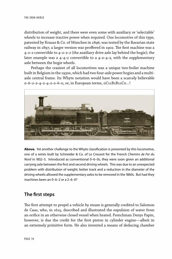
Above. Yet another challenge to the Whyte classification is presented by this locomotive, one of a series built by Schneider & Co. of Le Creusot for the French Chemins de Fer du Nord in 1852–5. Introduced as conventional 0–6–0s, they were soon given an additional carrying axle between the first and second driving wheels. This was due to an unexpected problem with distribution of weight; better track and a reduction in the diameter of the driving wheels allowed the supplementary axles to be removed in the 1860s. But had they machines been an 0–6–2 or a 2–6–0?
T H E D E V E LO P M E N T O F S T E A M T R A C T I O N O N T H E R A I LWAY
PA G E 1 1
pressure by sliding a weight along a bar, without realising that in this lay the basis of an effectual safety valve. Papin is said to have built a model road locomotive propelled by his piston and cylinder engine in 1698, but nothing else of note was done until 1757–8, when James Watt began research into the steam engine at the request of Dr James Robison of Glasgow University. His first model, never finished, was apparently of a steam powered road carriage.
The earliest full-size locomotive engine was created by the Frenchman Nicholas Cugnot, a small scale prototype built in 1759 being followed rapidly by a vehicle large enough to be considered as an artillery tractor. Unfortunately, the three wheeler was unstable and overturned on a bend. The project was then abandoned. In 1780, another Frenchman, Thomas Charles Auguste Dallery of Amiens, is said to have made a road locomotive fitted with a water tube boiler. The machine had a single central two wheeled axle with small balancing wheels at each end, but was no more successful than Cugnot’s had been.
Watt, Murdock, Symington, Evans and others experimented throughout the 1780s, but not until Richard Trevithick made the first of his road locomotives in 1801 was real progress made. Trevithick’s machine was destroyed by fire after making a trial trip or two and a replacement, demonstrated in London in 1803, was not successful enough to arouse interest. By this time, however, Richard Lovell Edgeworth, contributing to Nicholson’s Journal of Philosophy, Chemistry and the Arts in 1802, had become one of the first to suggest the application of steam power to wagon ways. He had in mind the use of stationary engines, though the first successful application was not made until 17th May 1809 on the Bewicke Main wagon way.
The need to construct railways in all kinds of terrain, to meet differing operating criteria, has created a wide range of locomotive equipment. Among the earliest problems was the inability of wooden and cast iron rails to bear the weight of locomotives which were powerful enough to be useful; another important limitation was the grip to be expected between smooth iron wheels riding on smooth surface iron rails, which would obviously limit the loads that could be hauled before slipping began. Whether this was the most effectual method of traction—indeed, even permissible—puzzled many early experimenters, until William Hedley built a mechanically powered test cart and proved that adhesion was sufficient by itself to be acceptable.
The earliest locomotives relied on beams, rods and levers to transmit power to the driving wheels. The first efforts (such as Trevithick’s) had only one cylinder, though the boiler pressure was higher than that used by Boulton & Watt’s stationary engines. Spent steam was exhausted directly into the atmosphere instead of a condenser. Relying on a single cylinder required a
T H E I R O N H O R S E
PA G E 1 2
heavy flywheel to smooth out the intermittent power supply, but a glance at the Trevithick model will show that the clumsy flywheel was a source of danger.
The Coalbrookdale Company was the first to build a horizontal-cylinder engine, designed by Richard Trevithick to run on a wagon way. Work had begun August 1802, but was stopped when the engine was ‘first started up’ (possibly owing to a boiler failure) and was then abandoned.
In 1804, Trevithick completed a locomotive engine for the Pen-y-Darren Ironworks near Merthyr Tydfil. The owner of the works, Samuel Homfray, had so much faith in the engine that he bet 500 guineas with Anthony Hill of the rival Plymouth Ironworks that ten tons of iron could be hauled on the 4ft 6in gauge wagon way from Pen y Darren to Abercynon. The wagon-way locomotive was successfully tested on 13th February 1804. It had a single 8¼×54in cylinder and ran at about forty strokes per minute, giving a speed of 4mph. The exhaust steam was turned from the cylinder up the chimney, forming a primitive blast pipe: an invention that was later claimed on behalf of Stephenson, Hackworth and many others. Steam was distributed to the cylinder through a four-way rotary valve, which was operated by tappets on a rod struck by a lug on the cross head. The only safety feature appears to have been a fusible plug, which may also be due to Trevithick. The plug melted if the boiler water evaporated and the temperature of the boiler wall rose too far.
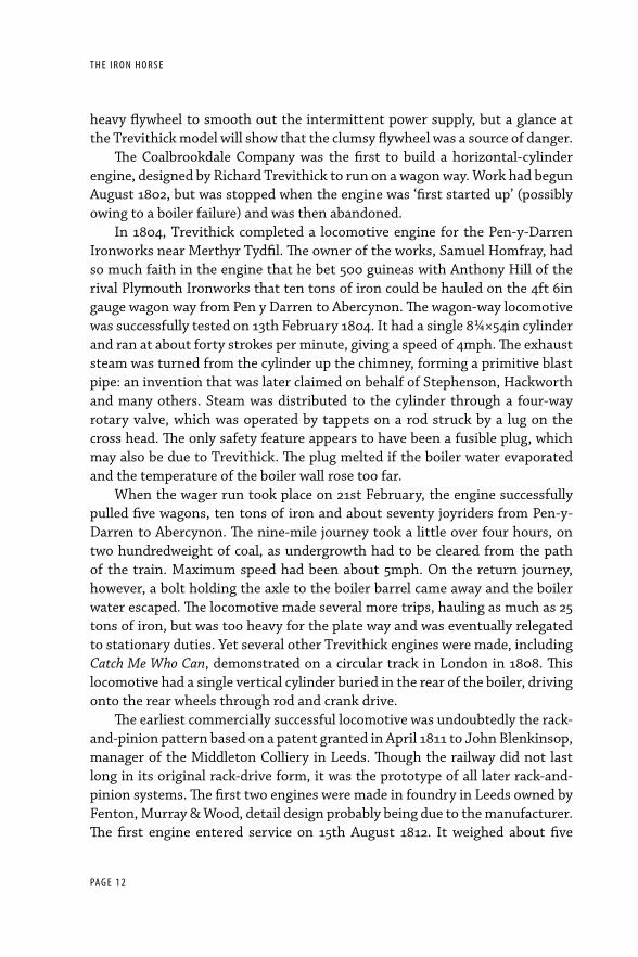
When the wager run took place on 21st February, the engine successfully pulled five wagons, ten tons of iron and about seventy joyriders from Pen-y-Darren to Abercynon. The nine-mile journey took a little over four hours, on two hundredweight of coal, as undergrowth had to be cleared from the path of the train. Maximum speed had been about 5mph. On the return journey, however, a bolt holding the axle to the boiler barrel came away and the boiler water escaped. The locomotive made several more trips, hauling as much as 25 tons of iron, but was too heavy for the plate way and was eventually relegated to stationary duties. Yet several other Trevithick engines were made, including Catch Me Who Can, demonstrated on a circular track in London in 1808. This locomotive had a single vertical cylinder buried in the rear of the boiler, driving onto the rear wheels through rod and crank drive.
The earliest commercially successful locomotive was undoubtedly the rack-and-pinion pattern based on a patent granted in April 1811 to John Blenkinsop, manager of the Middleton Colliery in Leeds. Though the railway did not last long in its original rack-drive form, it was the prototype of all later rack-and-pinion systems. The first two engines were made in foundry in Leeds owned by Fenton, Murray & Wood, detail design probably being due to the manufacturer. The first engine entered service on 15th August 1812. It weighed about five
T H E D E V E LO P M E N T O F S T E A M T R A C T I O N O N T H E R A I LWAY
PA G E 1 3
Ascribed to the great innovator Richard Trevithick (1771–1833), this model is believed to date from the early 1800s. The single cylinder, placed vertically, mirrors the constructionof Catch Me Who Can,which ran on a track in London throughoutthe summer of 1808.
PA G E 1 4
tons, and was powered by two vertical single-acting cylinders (said to have had a 9in bore and a 22in stroke) which drove a toothed pinion revolving between the carrying wheels. Suitable teeth were cast into the outside surface of the rails. The engines could haul ninety tons on level track, and even succeeded in in taking a fifteen-ton load up a slope. Several of them had been made by 1815.
The third Blenkinsop & Murray engine to run at Middleton Colliery had double-acting cylinders (its predecessors were rebuilt to this form), and eccentrics operated the valves instead of the original tappet gear. A fourth Middleton locomotive was fitted with a wooden condenser cistern above the boiler to receive steam exhausted from the cylinders, which otherwise frightened horses. Blenkinsop locomotives survived on the Middleton railway until 1834, when a brief return to horse traction was made before edge rails were laid for adhesion-type locomotives.
At this stage of railway history, the best method of propulsion was still to be discovered. This allowed some very strange designs to be produced. On 30th December 1812, a patent was granted to William and Edward Chapman to protect a vertical-cylinder chain haulage locomotive engine, the reduction of pressure on the track arising from the use of multiple axles, and the mechanical equalisation of load on the wheels by mounting them in pairs on swivelling trucks or bogies—an idea subsequently widely claimed as ‘novel’ in Britain and the USA. The oldest Chapman engine, possibly a four-wheeler, was built prior to February 1813 by Phineas Crowther in the Ouseburn Foundry, Newcastle upon Tyne, but was soon reconstructed with an additional axle. The four wheel wood-frame truck was attached to the underside of the boiler by a spherical pivot. One six-wheel example subsequently ran on the 4ft 5in gauge tramway in Heaton Colliery. It had two 8×24in cylinders and a cast iron return-flue boiler pressed to about 60lb/in². Power was taken from the cylinders by side levers driving chain wheels, guide pulleys and binding wheels. It was extensively rebuilt as a geared-adhesion type 0-6-0 about 1817. The pivoting four wheel truck was apparently retained, some play being allowed in the gears to accommodate lateral play.
In May 1813, Chapman & Buddle produced a promotional pamphlet containing drawings of an improved eight-wheel chain drive engine. An engine of this type may have been tried in Hetton Colliery in October 1813, but no other Chapman pattern engine is known to have been used until, on 21st December 1814, one built by Phineas Crowther pulled eighteen wagons (a load of 50-60 tons) up a 1-in-115 incline in Lambton Colliery. An account in the Newcastle Chronicle for 24th December confirms that the engine was an eight wheeler running on two four-wheel trucks.

T H E D E V E LO P M E N T O F S T E A M T R A C T I O N O N T H E R A I LWAY
PA G E 1 5
Not surprisingly, Chapman’s chain haulage system was not successful enough to survive against simpler methods of construction and rapidly disappeared. The development of the adhesion engine, relying on weight and friction between its wheels and rails to pull loads, is generally credited to William Hedley, Viewer of Wylam Colliery. As a patent granted to Hedley in 1813 mentions rope or chain haulage, however, the design of an eight-wheel locomotive run in the colliery in 1814–15 is open to doubt; it may even have been similar to the Chapman engine tried in nearby Lambton.
Writing in 1836, Hedley claimed to have built his first engine (a four wheeler) in March 1814 after experimenting with a man-power ‘adhesion truck’. He also claimed that the engines—there were eventually several of them—were too heavy for the track and had to be rebuilt as eight wheelers, before reverting to
Above. One of the locomotive engines built at Wylam Colliery to the designs of William Hedley. Note that the four axles were connected by gearing. After serving for a few years, improvements in the permanent way (and the introduction of superior designs) allowed the machines to be rebuilt in 0–4–0 form with side rods connecting the wheels.

T H E I R O N H O R S E
PA G E 1 6
Above. A fascinating geared-drive model, once owned by the British Engineerium but now in the National Museum of Science and Industry. Usually credited to Timothy Hackworth and probably dating from the early/mid 1820s, it has two cylinders buried in the boiler.

T H E D E V E LO P M E N T O F S T E A M T R A C T I O N O N T H E R A I LWAY
PA G E 1 7
0-4-0 type when edge rails were laid in 1828. Two surviving locomotives are credited to Hedley, blacksmith Timothy Hackworth and wheelwright Jonathan Forster: Puffing Billy in the Science Museum in London and Wylam Dilly in the Royal Scottish Museum in Edinburgh. Possibly made in Newcastle by Phineas Crowther, the former weighs about 8 tons 6 cwt in running order.
Both engines now have four wheels and the Freemantle design of parallel motion. However, though patented in 1803, Freemantle gear did not become commonplace until patent protection expired in 1817. This and other details suggest that their current appearance, arising from rebuilding in 1828-9, hides their original form. Thus the influence of Hedley on the development of the locomotive engine is very difficult to gauge.
Two cylinders driving through half-beams were used by almost everyone— George Stephenson included, on his Killingworth and Stockton & Darlington engines—until improved forms of drive were developed. A bell-crank lever was fitted to Stephenson’s Experiment of c. 1827, and a dummy crankshaft appeared in some of Hackworth’s earliest designs. Finally, Hackworth fitted the piston rod directly to the wheels of Royal George (even though a parallel motion was retained) and also coupled the six axles together. Stephenson’s Lancashire Witch, built for the Bolton & Leigh Railway in 1828, was the first to embody inclined cylinders and a cross-head to support the piston rod.
The advent of springs had much to do with the re-location of the cylinders. Combining springs and vertical cylinders was soon shown to be unwise, as the engine tended to lift from the track each time the pistons thrust downward. This could be so dangerous at speed that the cylinders were moved until they were placed diagonally, but even this proved to be unsatisfactory and they were soon made nearly horizontal.
Other innovations included the provision of better valves (the conventional ‘D’ type was patented by Matthew Murray in 1802), the introduction of multi-tube boilers, and a rudimentary appreciation of the value of a blast pipe.
The first public railways
The opening of the Stockton & Darlington Railway in 1825 is now regarded as one of the most important events in early railway history. However, the earliest engines, exemplified by Locomotion No. 1, were still derived from the beam engine and had vertical cylinders buried in the boiler. The first machine was ordered from Robert Stephenson & Company in September 1824, at a cost of £500, and delivered in September 1825. The prototype of four supplied
T H E I R O N H O R S E
PA G E 1 8
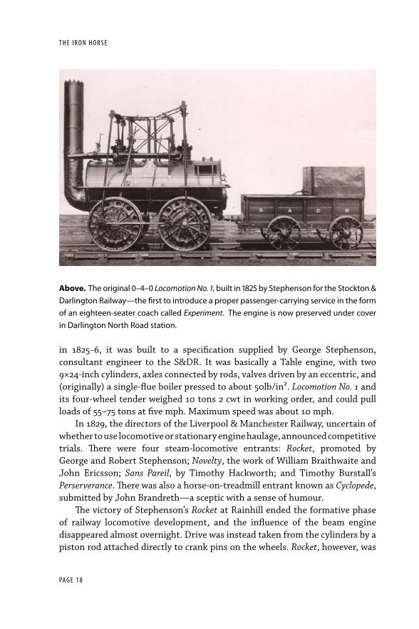
in 1825–6, it was built to a specification supplied by George Stephenson, consultant engineer to the S&DR. It was basically a Table engine, with two 9×24-inch cylinders, axles connected by rods, valves driven by an eccentric, and (originally) a single-flue boiler pressed to about 50lb/in². Locomotion No. 1 and its four-wheel tender weighed 10 tons 2 cwt in working order, and could pull loads of 55–75 tons at five mph. Maximum speed was about 10 mph.
In 1829, the directors of the Liverpool & Manchester Railway, uncertain of whether to use locomotive or stationary engine haulage, announced competitive trials. There were four steam-locomotive entrants: Rocket, promoted by George and Robert Stephenson; Novelty, the work of William Braithwaite and John Ericsson; Sans Pareil, by Timothy Hackworth; and Timothy Burstall’s Perserverance. There was also a horse-on-treadmill entrant known as Cyclopede, submitted by John Brandreth—a sceptic with a sense of humour.
The victory of Stephenson’s Rocket at Rainhill ended the formative phase of railway locomotive development, and the influence of the beam engine disappeared almost overnight. Drive was instead taken from the cylinders by a piston rod attached directly to crank pins on the wheels. Rocket, however, was
Above. The original 0–4–0 Locomotion No. 1, built in 1825 by Stephenson for the Stockton & Darlington Railway—the first to introduce a proper passenger-carrying service in the form of an eighteen-seater coach called Experiment. The engine is now preserved under cover in Darlington North Road station.
T H E D E V E LO P M E N T O F S T E A M T R A C T I O N O N T H E R A I LWAY
PA G E 1 9
soon improved. The thrust of the original pistons, which were set an angle of about 38 degrees to the rails, tended to lift the wheels clear of the rails at high speed. Consequently, on the engines delivered the Liverpool & Manchester Railway in 1830, the cylinders were set all but horizontally. Rocket was rebuilt to similar standards, acquiring new cylinders inclined at just eight degrees to the horizontal.
The use of two cylinders operating out of phase was already well established, as it allowed the engine to start even if one crank had stopped on dead centre and smoothed the transmission of power to the wheels. Though dummy crankshafts, bell-crank levers and other unusual power transmission systems were tried in the 1830s, the first locomotive to be designed with inside cylinders driving onto a crank axle was probably Timothy Hackworth’s Globe, ordered by the Stockton & Darlington Railway in February 1830; the earliest to be built, however, may have been Liverpool by Edward Bury.
Yet the first engine of this type to be truly successful was the work of Robert Stephenson. The 2–2–0 Planet was ordered by the Liverpool & Manchester Railway in the summer of 1830, run experimentally on 23rd November, and then set to haul an eighty-ton load from Liverpool to Manchester on 4th December. The journey was successfully completed in 2hr 54min. Planet was a small engine of about eight tons, with a multi-tube boiler, and wheel diameters of 3ft 1in (leading) and 5ft (driving). Placing the two 11×16in cylinders under the smokebox not only reduced heat losses but also increased efficiency.
The easiest way to improve the performance of a ‘Planet’ type engine was to enlarge the boiler, requiring an additional carrying axle beneath the firebox. 0-4-2 derivatives of the basic 2–2–0 pattern appeared in the autumn of 1832, but the perfected design was the subject of English Patent 6484, granted to Robert Stephenson on 7th October 1833. The trailing axle allowed a larger firebox and boiler, with enlarged heating surfaces and better steam-raising capabilities. A steam brake was fitted and flangeless driving wheels were intended to avoid breakage of crank axles.
The first engine, Patentee, was eventually acquired by the Liverpool & Manchester Railway in April 1834 for £1000. The locomotive had two 11×18in cylinders and weighed 11 tons 9 cwt without its four-wheel tender. The first 0-6-0 of this form, intended for banking and heavy freight, was supplied by Stephenson to the Leicester & Swannington Railway in September 1833; it had 4ft 6in diameter coupled wheels, two 16×20in inside cylinders, and weighed about seventeen tons.
The success of even the earliest railways increased the loads engines were expected to pull. This was answered simply by making them bigger; boilers
T H E I R O N H O R S E
PA G E 2 0
increased in diameter and had more fire tubes, increasing the amount of water that could be turned to steam and allowing cylinders to be enlarged; boiler pressures rose, forcing the development of adequate safety valves; driving wheels were enlarged so that the distance travelled with each rotation grew.
Stability problems were solved by moving cylinders from vertical, then diagonal to horizontal; by adding axles and, particularly, the development of bogies or pivoting trucks to guide engines around curves. The first bogie had been patented in 1812 by William Chapman; Isaac Dripps of the Camden & Amboy Railroad was the first to fit a pilot (or ‘cowcatcher’) and a pony truck, when, in 1832, he converted a Stephenson made 0-4-0 to 2-2-2.
For all these changes, however, the inside-cylinder design pioneered by Planet in 1830 remained practically unchanged in Britain into the twentieth century. The most important innovations in this period concerned the valve gear, which allowed the expansive properties of steam to be used to their best effect. This increased power while often reducing the consumption of coke. The valve-gear system patented in 1842 by Williams and Howe is now better known as "Stephenson’s", though Stephenson himself always tried to give credit where it was rightly due. It was used until the very end of the steam age, alongside a rival mechanism patented in Belgium in 1844 on behalf of Egide Walschaert.
The search for speed
One of the most distinctive nineteenth-century locomotive was patented by Thomas Russell Crampton (1816–88), whose engines—generally with single driving axles—were intended to pull comparatively modest loads at high speed. The trailing axle lay immediately behind the fire box, where it was driven (in the earliest designs at least) by outside cylinders placed between the widely spaced carrying axles. The first of these engines was made for the British-owned Liége & Namur Railway (in Belgium) by Tulk & Ley of Whitehaven, Cumbria. Completed in 1846, this 4-2-0 had 7ft-diameter driving wheels and cylinders measuring 16×20in. Crampton-type engines were then tested on the London & North Western Railway, culminating in the unique 6-2-0 Liverpool, built in 1848 by Bury, Curtis & Kennedy. This 35-ton monster, with 8ft drivers and two 18×24in cylinders, allegedly attained 75mph with a light train. Unfortunately, the rigidity of its wheelbase damaged the light and poorly laid track, and the ultimate success of the Crampton system was achieved in France.
Advances in technology in the 1850s were generally confined to details, such as the introduction of split rings on solid-head pistons, credited to John
T H E D E V E LO P M E N T O F S T E A M T R A C T I O N O N T H E R A I LWAY
PA G E 2 1
Ramsbottom. The Frenchman Paul Giffard developed the first practicable injector, and the prolific Ramsbottom produced his duplex-spring safety valve. Trials were also successfully undertaken to enable cheap coal to be used instead of expensive coke, the change being almost entirely due to improvements in firebox design.
In 1851, the year of the Great Exhibition held in London, a competition was held in Austria to find a locomotive that could successfully work on a railway line over the Semmerling Pass, where steep gradients and high altitude were widely believed to make locomotive haulage impossible. The competition produced three differing approaches to articulation: Seraing, built by Cockerill of Belgium; Wiener Neustadt, by Günther of Vienna; and Bavaria, by Maffei of Munich. The Belgian locomotive is generally regarded as the prototype of the Fairlie system, whilst the Wiener Neustadt pre-empted the Meyer.
The locomotives shown in London in 1862, considered as a group, contained several improvements over those displayed eleven years earlier. A major advance had been the advent of efficient means of burning cheap coal instead of expensive coke. Even though the development was still imperfect,
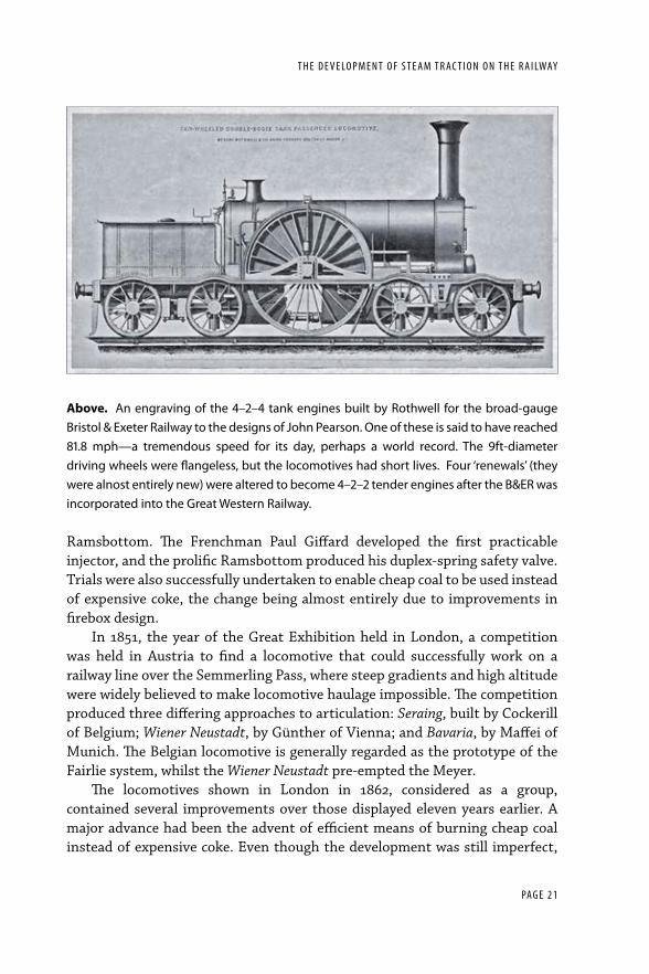
Above. An engraving of the 4–2–4 tank engines built by Rothwell for the broad-gauge Bristol & Exeter Railway to the designs of John Pearson. One of these is said to have reached 81.8 mph—a tremendous speed for its day, perhaps a world record. The 9ft-diameter driving wheels were flangeless, but the locomotives had short lives. Four ‘renewals’ (they were alnost entirely new) were altered to become 4–2–2 tender engines after the B&ER was incorporated into the Great Western Railway.
T H E I R O N H O R S E
PA G E 2 2
the 1862 engines incorporated ‘smoke-consuming’ fireboxes, double or divided; air-assisted combustion; brick deflector arches; and a host of other innovative ideas. There were better means of following the curves in track—articulation and radial axles, for example—and the perfection of the Giffard injector, patented in France in 1857, allowed manually-operated feedwater pumps to be abandoned. Another major change lay in the rejection of ultra-low centres of gravity, which in 1851 had been considered essential if high speeds were to be attained on standard-gauge track. These ideas had been typified by the ideas of Thomas Crampton, which persisted in France long after they had been rejected in Britain.
The catalogues of the 1862 exhibition reveal exhibits ranging from the cheapest contractors’ engines to oddities emanating from France. Some observers detected fundamental differences between engineering practice in Britain (where speed was often paramount but adhesive weight was not) and Continental Europe, where slow-speed slogging up lengthy banks required small wheels and as much adhesive weight as possible. Consequently, the major British exhibits included a 2-2-2 express passenger engine designed by John Ramsbottom for the London & North Western Railway. Built in the company workshops in Crewe, the locomotive had driving wheels with a diameter of 7ft 7½in, a fixed wheelbase measuring fifteen feet, and two 16×24in cylinders mounted externally. The fire-grate had an area approaching 15ft², and the heating surface totalled 1098ft².
The Civil War raging in the USA prevented transatlantic exhibits, but the European manufacturers arrived in force. Among them were some remarkable achievements, though British journalists tended towards disparaging comments on the grounds that the ‘foreign’ designs were either too complicated or failed to follow the established chimney first/cab last layout. The Austrian section included Duplex, a 4-2-0 designed by John Haswell for the Royal Austrian State Railway. Its characteristics included driving wheels 6.74ft in diameter and a short fixed wheelbase, owing to the absence of a bogie, of about eleven feet. Four cylinders provided the locomotive’s most unusual feature. Mounted externally, each had an 11in bore and a 25in stroke, the area of the fire-grate being 15ft² and of the heating surface, about 1344ft². The engine weighed about 32 tons in working order, 12·5 being carried on the driven axle.
Haswell placed the cylinders outside the frames, each pair driving onto a double-ended crank attached to driving wheels which were carried inside the plate frame. The goal was to eliminate vibration by balancing the rotational forces created in a normal two-cylinder design. To demonstrate his ideas to sceptical observers, Duplex was tested by running at 400 rpm while suspended
T H E D E V E LO P M E N T O F S T E A M T R A C T I O N O N T H E R A I LWAY
PA G E 2 3
above the ground—the equivalent of 96 mph! The horizontal oscillation was merely one twelfth of an inch, vertical movement being one fifth. The engine had been tested on the Austrian railway at 70 mph, proving, as predicted, to run with praiseworthy steadiness, but it was too complicated to be durable and had a short service life.
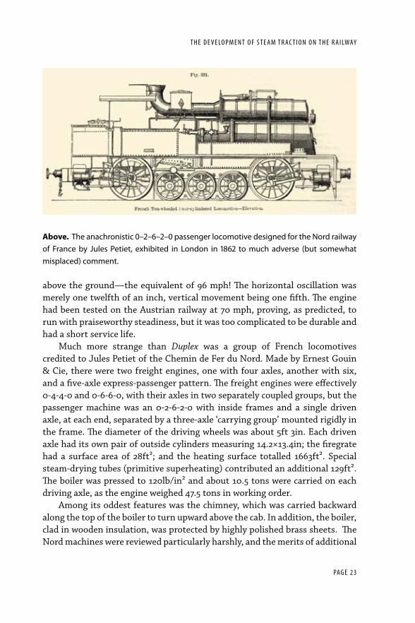
Much more strange than Duplex was a group of French locomotives credited to Jules Petiet of the Chemin de Fer du Nord. Made by Ernest Gouin & Cie, there were two freight engines, one with four axles, another with six, and a five-axle express-passenger pattern. The freight engines were effectively 0-4-4-0 and 0-6-6-0, with their axles in two separately coupled groups, but the passenger machine was an 0-2-6-2-0 with inside frames and a single driven axle, at each end, separated by a three-axle ‘carrying group’ mounted rigidly in the frame. The diameter of the driving wheels was about 5ft 3in. Each driven axle had its own pair of outside cylinders measuring 14.2×13.4in; the firegrate had a surface area of 28ft²; and the heating surface totalled 1663ft². Special steam-drying tubes (primitive superheating) contributed an additional 129ft². The boiler was pressed to 120lb/in² and about 10.5 tons were carried on each driving axle, as the engine weighed 47.5 tons in working order.
Among its oddest features was the chimney, which was carried backward along the top of the boiler to turn upward above the cab. In addition, the boiler, clad in wooden insulation, was protected by highly polished brass sheets. The Nord machines were reviewed particularly harshly, and the merits of additional
Above. The anachronistic 0–2–6–2–0 passenger locomotive designed for the Nord railway of France by Jules Petiet, exhibited in London in 1862 to much adverse (but somewhat misplaced) comment.
T H E I R O N H O R S E
PA G E 2 4
cylinders were lost in complaints of complexity. There was sometimes little to choose between two- and four-cylinder engines of otherwise similar dimensions (as the limitations on cylinder diameter were usually applied by the steam-raising capacity of the boiler), yet extra cylinders not only prevented dimensions becoming too large, but also had the merit of smoothing the ride.
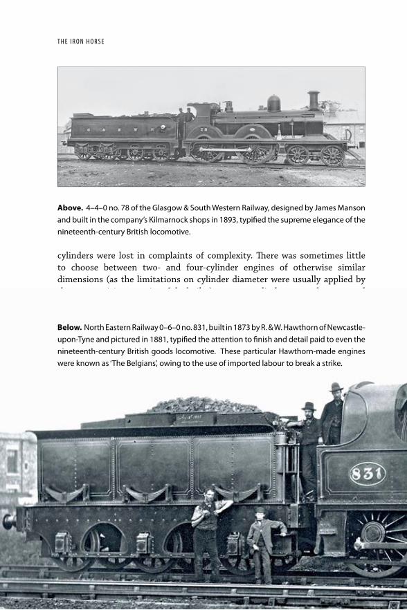
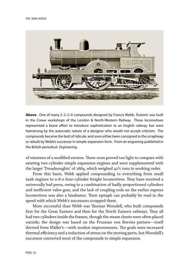
Below. North Eastern Railway 0–6–0 no. 831, built in 1873 by R. & W. Hawthorn of Newcastle-upon-Tyne and pictured in 1881, typified the attention to finish and detail paid to even the nineteenth-century British goods locomotive. These particular Hawthorn-made engines were known as ‘The Belgians’, owing to the use of imported labour to break a strike.
Above. 4–4–0 no. 78 of the Glasgow & South Western Railway, designed by James Manson and built in the company’s Kilmarnock shops in 1893, typified the supreme elegance of the nineteenth-century British locomotive.
T H E D E V E LO P M E N T O F S T E A M T R A C T I O N O N T H E R A I LWAY
PA G E 2 5
The search for efficiency
Though experiments with a continuous-expansion steam system were made in Britain in the 1860s, the work of a railwayman named John Nicholson, the first successful embodiment of compounding in a railway engine occurred when Anatole Mallet built an 0-4-2 tank engine in 1876: inspired, no doubt, by the success of Woolf-type compound stationary engines in France.
By 1889, and the Exposition Universelle in Paris, the first steps towards an efficient compound railway engine had been taken. Interestingly, many of the earliest were taken in Britain, but the unhappy experience dealt compounding a blow from which it never recovered. The villain of the piece was Francis Webb, a very skilful engineer who, by the early 1880s, had risen to the position of Locomotive Superintendent of the London & North Western Railway. Impressed by Mallet’s small compound tank engine, Webb determined to build comparable engines in Britain.
After converting an old 2-4-0 engine as a trial, Webb built the three-cylinder 2-4-0 Experiment with two high-pressure cylinders outside the frames and a single large low-pressure unit inside. Webb stated the principal goals as a reduction in fuel consumption and the elimination of coupling rods. Hard running showed that the engine worked satisfactorily, so Webb built the first
T H E I R O N H O R S E
PA G E 2 6
of nineteen of a modified version. These soon proved too light to compare with existing two-cylinder simple expansion engines and were supplemented with the larger ‘Dreadnoughts’ of 1884, which weighed 42½ tons in working order.
From this basis, Webb applied compounding to everything from small tank engines to 0-8-0 four-cylinder freight locomotives. They have received a universally bad press, owing to a combination of badly proportioned cylinders and inefficient valve gear, and the lack of coupling rods on the earlier express locomotives was also a hindrance. Their epitaph can probably be read in the speed with which Webb’s successors scrapped them.
More successful than Webb was Thomas Worsdell, who built compounds first for the Great Eastern and then for the North Eastern railways. They all had two cylinders inside the frames, though the steam chests were often placed outside; the design was based on the Prussian von Borries pattern—itself derived from Mallet’s—with modest improvements. The goals were increased thermal efficiency and a reduction of stress on the moving parts, but Worsdell’s successor converted most of the compounds to simple expansion.
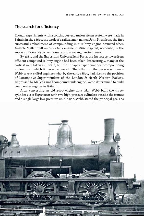
Above. One of many 2–2–2–0 compounds designed by Francis Webb, Teutonic was built in the Crewe workshops of the London & North-Western Railway. These locomotives represented a brave effort to introduce sophistication to an English railway, but were hamstrung by the autocratic nature of a designer who would not accept criticism. The compounds became the butt of ridicule, and soon either been consigned to the scrapheap or rebuilt by Webb’s successor in simple-expansion form. From an engraving published in the British periodical Engineering.
T H E D E V E LO P M E N T O F S T E A M T R A C T I O N O N T H E R A I LWAY
PA G E 2 7
Between 1886 and 1892, more than two hundred Worsdell-von Borries compounds were made; most were 0-6-0 goods engines, but there were also twenty high speed 4-2-2s. Though not without constructional problems, these engines were surprisingly efficient. Unfortunately, success on a provincial railway was not enough to overcome prejudice based on the L&NWR experience.
Few of the railway engines exhibited from the time of the Great Exhibition of 1851 to the Paris Exhibition of 1878 showed much originality, however much they differed in detail. Articulated locomotives were offered, particularly to haul heavy loads up steep gradients or around sharp curves, and some curious prototypes could be seen. Yet Britain was represented in Paris in 1889 only by a handful of commonplace designs: a 4-2-2 from the Midland Railway; Onward, a 4-4-0 of the South Eastern Railway; and the ‘Gladstone’ 0-4-2 Edward Blount of the London, Brighton & South Coast Railway. All three engines had inside cylinders. They were Victorian railway engineering at its best: solid, dependable enough, beautifully finished, pleasing to the eye, stunningly colourful, but technically uninspired.
The greatest exponents of compounding were French: perhaps fittingly, as the initial success of the compound stationary engine was gained largely in France. Among the Paris exhibits in 1889 was a 2-6-0 goods engine designed for the Nord railway by Eduard Sauvage. Built in 1887, the engine had a central high-pressure cylinder (initially 18.11in, then 17×19.69in) and two 27.56×19.69in outside cylinders driving the central driving axle. The low-pressure cranks were set at 90 degrees, with the high-pressure crank at 135 degrees to each of them. Trials returned a drawbar pull of 9,700lb, achieved whilst hauling a 540-tonne train up a gradient of 1 in 200, and 620 tonnes were taken up the same slope at 20kph (12½mph). However, owing to its small wheels, with a diameter of only 1.65m, the Mogul was not as influential as its design deserved to have been; it was not perpetuated, even though Sauvage became an influential teacher and a fluent champion of compounding. Perversely, the Paris jurors awarded the 4-2-2 ‘Midland Single’ the coveted Grand Prix in the class!
A contemporary of Sauvage’s modest 2-6-0, unnoticed at Paris, was a 2-2-2-0 made for the Nord railway in 1886 by Société Alsacienne de Constructions Mecaniques. Designed by Alfred de Glehn, this engine had two high-pressure cylinders between the frames, driving the front axle, and two larger low-pressure units outside driving the rear axle. A inverted form of Walschaert gear was used, and the system of valving permitted the driver to chose two-cylinder simple expansion (using either set of cylinders), four-cylinder simple expansion, or ‘reinforced compound’ operation where some high-pressure steam could be admitted to the low-pressure receivers to boost power.
T H E I R O N H O R S E
PA G E 2 8
Ironically in view of the lack of success of the Webb compounds, de Glehn also failed to couple the driving wheels—for the same reason as Francis Webb was doing at much the same time in Britain. The difference may have been simply that no one dared confront Webb, whereas de Glehn was merely the servant of the railway that had commissioned the locomotives from SACM.
The 2-2-2-0 was then taken by Gaston du Bousquet, newly promoted to the post of locomotive superintendent, as the basis for a Nord 4-4-0. This in turn promoted a range of 4-4-2s, 4-6-0s and 4-6-2s which were much more than the equal of simple-expansion locomotive of similar dimensions. The saturated compound 4-4-2 of the early 1900s, which weighed only 65 tons, could take loads of 300-350 tonnes at 75mph and develop 1400ihp at these speeds.
The fast-growing success of the de Glehn/du Bousquet locomotives caused another look to be taken at compounding by the British. The Great Western Railway experimented in the early 1900s with three locomotives imported from France, before settling on four-cylinder simple expansion, but the use of English drivers may have been sufficient to prejudice the results.
The best work in Britain was done by Walter Smith, chief draftsman of the North Eastern Railway, who modified a Worsdell simple-expansion 4-4-0 to a three-cylinder compound system in 1898. This had a central high pressure cylinder exhausting to two external low-pressure units, with the 90 degree/135
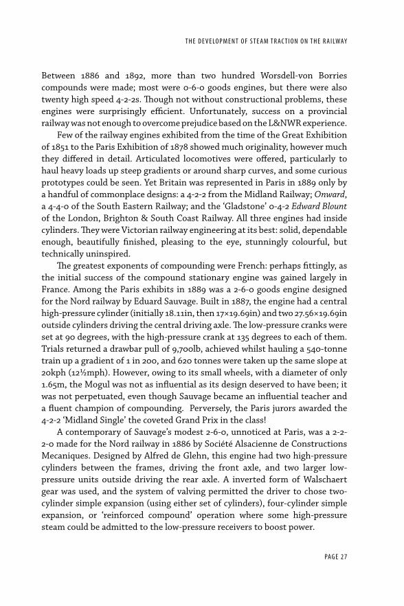
Above. Among the most promising compound locomotives ever to run in Britain, nos. 730 and 731 of the North Eastern Railway (with Stephenson and Walschaert valve-gear respectively) were built in Gateshead works in 1906 to the designs of W.M. Smith. They had two high-pressure 141/4×26-inch cylinders inside and two low-pressure 22×26-inch cylinders outside, all four driving the leading axle.

T H E D E V E LO P M E N T O F S T E A M T R A C T I O N O N T H E R A I LWAY
PA G E 2 9
degree crank settings pioneered by Edouard Sauvage on the Nord railway in France. Separate control gear was fitted and high-pressure steam could be admitted to the low-pressure cylinders to start the engine away.
This locomotive remained a prototype on the NER, though well regarded. It inspired a handful of three-cylinder compound Atlantics on the Great Central Railway and the Smith-Johnson 4-4-0s on the Midland Railway, the first of which dated from 1902. Richard Deeley then built substantial numbers of a slightly modified pattern—the ‘Midland Compound’—after he had succeeded Johnson in 1906. These were popular and smooth running engines, but were handicapped above 60mph by poor steam-passage design.
Smith’s final design, completed in 1904, was a four-cylinder compound Atlantic with two high-pressure cylinders inside the frames exhausting to two external low-pressure units. Two examples of this first-class design were built for the North Eastern Railway in 1906, one with Stephenson valve gear and the other with Walschaert’s, but the sudden death of Smith brought work to an end. The NER wanted to build more of them, but the mercenary attitude of Smith’s executors forced the substitution of heavy three-cylinder simple-expansion locomotives developing comparable power. These engines worked well enough, but consumption of coal and water increased.
Below. French railways were particularly fond of compounding, which gave substantial economies when comparatively poor-quality coal was used. This ‘Serie 11’ 4–6–0 of the Chemin de Fer de l’Est, no. 3112 dating from 1907, had two high-pressure cylinders of 29cm diameter exhausting into two 39cm-diameter low-pressure units.
T H E I R O N H O R S E
PA G E 3 0
The advent of multiple cylinders renewed the quest for speed, producing not only some of the most impressive looking of all railway engines but also contributing greatly to thermodynamic improvement in the genre. The first properly authenticated 100mph record is generally attributed to an American 4-4-2, which recorded 103·5mph whilst undergoing brake trials in the mid 1930s, but it was soon obvious that there was a finite limit for a conventional steam engine, deciding factors including the diameter of the coupled wheels and the piston speed. Though the standard Gresley Pacific Papyrus attained 108mph during high speed trials in 1936, streamlining was deemed to be advantageous.
The French had already made a large series of the so-called Coupe-Vents or ‘Windcutters’ for the line that ran to the South of France by way of Lyon. Fairings on the smokebox, chimney, cab and sometimes over the cylinders had been shown to reduce the drag when the train was headed directly into the Mistral. Few attempts were made elsewhere until the belated acceleration of steam hauled services in the 1930s. The die was cast when a brand-new streamlined 4-6-4 claimed the record for Germany in 1935, attaining 124·5mph; this was subsequently bettered by the LNER 4-6-2 Mallard, which sustained
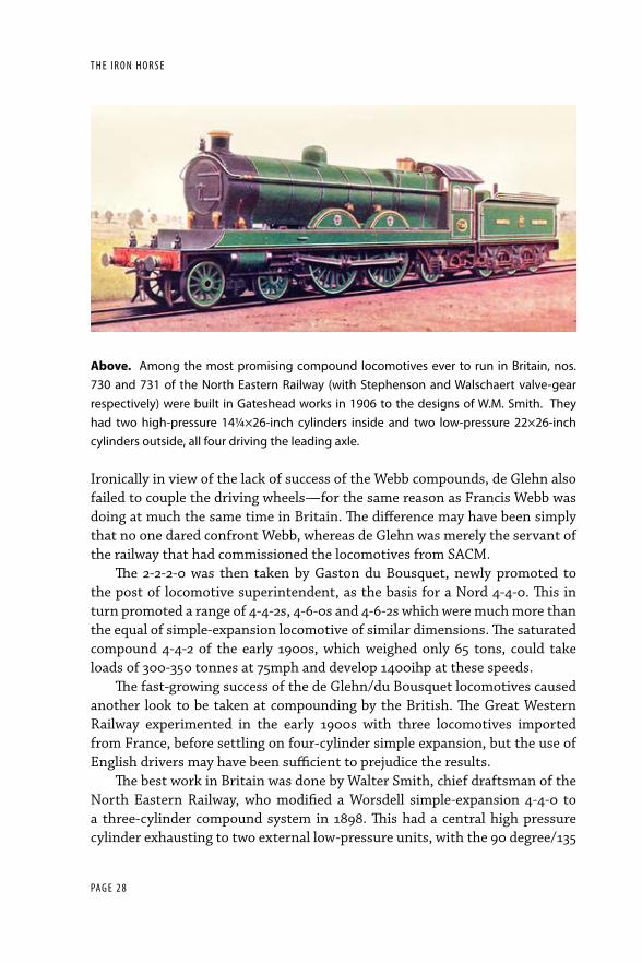
Below. A 2–6–0 ‘Crab’ of the London Midland & Scottish Railway, designed in Horwich (the manufactory of the Lancashire & Yorkshire Railway) in 1925–6, shortly after the Grouping of 1923 amalgamated British railways. With 5ft 6in wheels and two 21×26-inch cylinders, it typifies the mixed-traffic engines of the period between the world wars. Note the external Walschaert valve gear, which was becoming increasingly popular in Britain at this time.
T H E D E V E LO P M E N T O F S T E A M T R A C T I O N O N T H E R A I LWAY
PA G E 3 1
125mph with a short-duration burst of 126mph down Stoke Bank in the summer of 1938.
These figures were almost always attained with lightweight trains, but they did point the way to better things; both the LNER and the LMS. ran streamlined services that were capable of running at more than 100mph for long distances. Comparable rivalry in the USA produced not only an extraordinary series of streamlined locomotives but also some impressive ‘speed with load’ records. Amongst the best of these were achieved with the Pennsylvania’s 4-4-4-4 Duplex T1 locomotives which, though one of railway history’s fiascos, could haul thousand-ton trains at more than 100mph…but only if the conditions were right.
Efforts were also being made to improve the thermal efficiency of the steam locomotive, much of the best work being undertaken in France. Every major pre-nationalisation French railway used compounds, four-cylinder patterns being most common though a few had two cylinders (usually rebuilds of old stock) and the SNCF designs almost always had three. The encouragement of compounding in the period between the world wars was largely due to the
T H E I R O N H O R S E
PA G E 3 2
genius of André Chapelon, whose 1929 transformation of a Paris–Orléans 4-6-2 had verged on miraculous. From an engine that could develop about 1850ihp, Chapelon obtained 3000ihp at 75mph. Later conversions raised this to 3700ihp, largely owing to streamlined steam passages and oscillating-cam poppet valves driven by Walschaert gear. Chapelon’s masterpiece was 4-8-4 No. 242A1, which could generate 5500ihp in the cylinders (equivalent to about 4200hp at the drawbar). Coal consumption was only 1.87lb/dbhp at 2200dbhp, rising to a miserly 2.65lb/dbhp at 4000dbhp at 62.5mph.
Articulation
Enlargement of rigid-frame locomotives in a search for power had drawbacks. Either the diameter of the driving wheels had to be reduced to fit within a specific wheelbase, generally lowering the speed that could be attained without wearing the valve gear, or the wheelbase had to be extended so that the wheel diameter could remain unchanged. Extending the rigid wheelbase too far
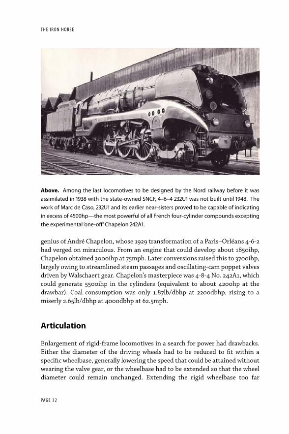
Above. Among the last locomotives to be designed by the Nord railway before it was assimilated in 1938 with the state-owned SNCF, 4–6–4 232U1 was not built until 1948. The work of Marc de Caso, 232U1 and its earlier near-sisters proved to be capable of indicating in excess of 4500hp—the most powerful of all French four-cylinder compounds excepting the experimental ‘one-off’ Chapelon 242A1.
T H E D E V E LO P M E N T O F S T E A M T R A C T I O N O N T H E R A I LWAY
PA G E 3 3
confined the locomotive to well-laid main line track with gentle curves, and restricted its utility greatly. The provision of flangeless wheels and axles that could move a short distance laterally eased some of the problems, as did the provision of bogies and swivelling trucks. But they were not the entire answer, and articulation often seemed a better alternative.
Though Englishman Matthew Murray proposed a design unsuccessfully in the mid 1820s, the first articulated locomotive to be built was the work of Horatio Allen in 1831-2. This ran in the U.S.A. on the South Carolina Railroad and had two twin-boiler units connected by a central firebox. It had two cylinders and a theoretical 2-2-2-2 wheel notation, but was not especially successful in service.
The Mallet became by far the most popular of all the systems of articulation, though this was at least partly due to its espousal by the most influential railroads in the U.S.A. Its history began with a French patent granted to Anatole Mallet in 1884. In 1887, the Decauville company realised that the Mallet system (then conceived as a compound) was an ideal way of providing a 60cm gauge engine that could haul loads equal to its own weight on eight per cent gradients (1 in 12.5), travel safely around curves with radii as sharp as 20 metres, yet have an axle loading of less than three tonnes. The Decauville 0-4-4-0T Mallet carried the front power unit on a Bissell truck, pivoted to the frame roughly beneath the mid point of the boiler. Overall length was only 17ft 8in, weight in working order being about 11.6 tonnes. High pressure steam was supplied directly to the rear cylinders, then exhausted into a receiver from where it was taken to the front or low-pressure cylinders by a flexible pipe. Locomotives of this type gained renown on the 60cm gauge ‘Inner Circle’ track laid at the Exposition Universelle, Paris, in 1889. More than six million passengers were carried without a single serious incident.
Prior to about 1902, no notice of the Mallet had been taken in North America, where the heaviest freight traffic was being moved by large rigid-frame locomotives such as 2-10-0s and 2-10-2s, 162 tandem compounds of this type being made for the Atchison, Topeka & Santa Fé Railroad in 1902-7. Unfortunately, the inflexible wheelbase and high axle loading of these engines confined them to well-laid track with shallow curves. In 1903, however, the American Locomotive Company of Schenectady built a 0-6-6-0 Mallet for the Baltimore & Ohio Railroad. The engine had two high-pressure cylinders measuring 20×32in, two low-pressure units of 32×32in, and 4ft 8in coupled wheels. It weighed 212.5 tons with its tender.
Exhibited at the St Louis World’s Fair in 1904, this Alco Mallet was the butt of much criticism from engineers who were contemptuous of its great weight,

T H E I R O N H O R S E
PA G E 3 4
the method of articulation, and the design of the flexible steam pipes. When the Mallet entered service after the fair had closed, it proved much more successful than anyone excepting its promoters had anticipated. Minor problems were soon cured and a reputation for great power was gained. There followed an undignified scramble to develop the biggest and most powerful Mallet-type locomotives imaginable, the rivalry between the major U.S. railroads being matched only by rivalry between Baldwin and the American Locomotive Company (‘Alco’), formed by the amalgamation of several lesser lights in 1901.
The Mallet design also proved to be popular in Europe. By 1914, about 2500 had been made by Decauville and Batignolles in France; by Borsig and Henschel in Germany; by the Hungarian state factory; by Putilov and Kolomna in Russia; and by the Swiss Locomotive Works in Winterthur. A few had even been built in Britain by the North British Locomotive Co. Ltd of Glasgow, beginning with four 0-6-6-0 engines made for China in 1907-9. The largest of all conventional two-unit Mallets were the ten 2-10-10-2 examples built in 1918 for the Virginian Railroad by the American Locomotive Company. Intended to bank 15,000 ton freight trains over Clark’s Gap, they lasted until the late 1940s.
Though some railroads retained faith in compound Mallets until the end of steam in North America—there was little doubt that they ran more economically than the simples—a majority preferred simplicity in the years after the end of the First World War, when the diameter of the low-pressure cylinders had grown so large that they became increasingly difficult to fit within even the generous US loading gauge. Improvements in manufacturing techniques allowed simple-expansion versions to be made with boilers pressed to new heights, even though the two ‘Standard Mallets’ promoted by the U.S. Railroad Administration in the immediate post-1919 period retained compound working.
The first simple-expansion Mallets (not what the inventor had intended!) seems to have been a 2-4-4-0 in use on Trans-Siberian Railway in 1902, followed by a 2-8-8-2 and a 2-8-8-0 on the Pennsylvania Rail Road (1912 and 1919 respectively), but none were successful. A simple-expansion 2-6-6-2 was made by Baldwin for the Baltimore & Ohio Railroad in 1930, with 70in-diameter diring wheels, and a 2-6-6-4 was supplied to Seabord Air Line in 1935. But the first truly successful simple-expansion Mallet was the 4-6-6-4 Challenger introduced by the Union Pacific Railroad in 1936.
The 25 examples of the Union Pacific Railroad ‘Big Boy’ class 4-8-8-4 Mallets of 1941-4 were the largest steam locomotives ever made. Made by the American Locomotive Company, Big Boys had four enormous cylinders — 23¾×32in — and 5ft 8in driving wheels. A boiler pressure of 300 lb/sq.in gave a nominal
T H E D E V E LO P M E N T O F S T E A M T R A C T I O N O N T H E R A I LWAY
PA G E 3 5
tractive effort of 135,375lb. The locomotives could develop more than 6000hp at the drawbar could haul hundred-car freight trains weighing up to four thousand tons over a hilly section of the Union Pacific. Though speeds rarely exceeded 40mph, the huge machines could reach eighty if pushed. A typical example of the 1941 batch measured 132ft 10in overall, 16ft 2½in high, 10ft 10in wide, and weighed a staggering 1,189,500lb. The enormous tenders held 24,000 U.S. gallons of water and 56,000lb of coal.
An attempt was also made to perfect the so-called Triplex or Henderson Mallet, with a fixed central power truck and articulated trucks at each end. Exhaust from the central high-pressure cylinders was split between two pairs of low-pressure cylinders positioned on the pivoting trucks. Though this enabled six identical cylinders to be fitted, the added complication and loss of heat from the attenuated steam pipes proved to be the undoing of the Triplex system. Only five locomotives seem to have been made, all by the Baldwin Locomotive Company. The prototype was Matt H. Shay, a 2-8-8-8-2 delivered to the Erie Railroad in 1913. Trials showed that tremendous loads could be hauled on level track (on one occasion, 16,300 tons were drawn at 14mph) but also that the boiler could not supply steam fast enough to reach higher speeds. This was partly due to a reduction in draught, as the rearmost cylinders exhausted to the atmosphere through an auxiliary chimney at the rear of the tender.
The most powerful railway locomotive of all time, on the basis of tractive effort, was 377-ton Baldwin-made 2-8-8-8-4T Triplex Mallet no. 700, dating from 1916. This had two high-pressure and four low-pressure 36×32in cylinders and a nominal tractive effort, with all cylinders working on simple expansion, of 199,560lb. However, the boiler would not supply sufficient steam at more than 10-15mph, so No. 700 was reconstructed as two separate engines in 1921.
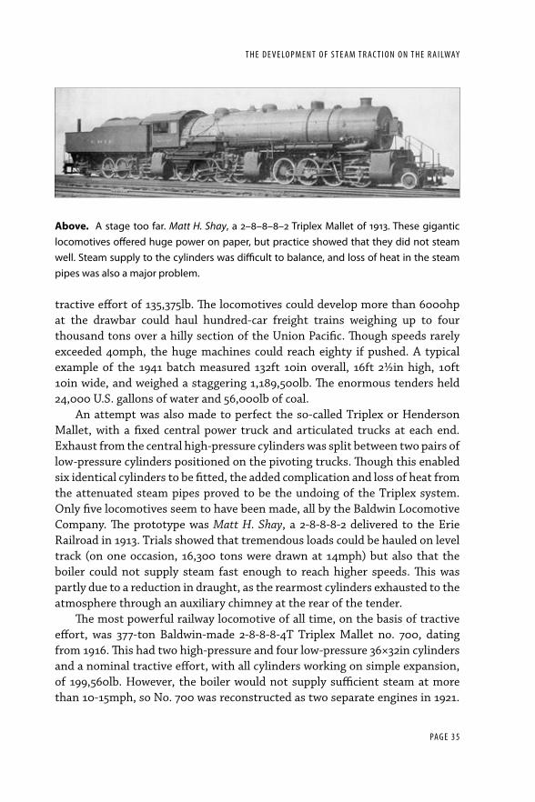
Above. A stage too far. Matt H. Shay, a 2–8–8–8–2 Triplex Mallet of 1913. These gigantic locomotives offered huge power on paper, but practice showed that they did not steam well. Steam supply to the cylinders was difficult to balance, and loss of heat in the steam pipes was also a major problem.
T H E I R O N H O R S E
PA G E 3 6
A design for a gigantic Quintuplex locomotive (2-8-8-8-8-8-2), with two cabs, is said to have been considered by Baldwin in 1916, but never left the drawing board. The problems of maintaining a good supply of steam had defeated even the 2-8-8-8-4 ‘Virginian’ Triplex Mallet, which had merely 75 sq.ft of grate area, and would have presented even more of a problem with ten cylinders and five sets of driving gear!
Whereas the Mallet was at its best in the USA, all but unencumbered by loading gauge restrictions and assured of good quality track, the Garratt was favoured in areas where heavy loads had to be hauled over undulating, lightweight track with severe curves. The competing designs rarely co-existed: the Garratt ousted its rival from southern Africa, whereas the success of the Mallet in North America prevented the Garratt attaining even a toehold. Only in South America (particularly Brazil) were there Garratts and Mallets in quantity.
Patented in 1907 by Herbert W. Garratt, Inspecting Engineer of the New South Wales Government Railways, the principal claim to novelty was the attachment of a short, large diameter boiler unit to the end of two power trucks. Each truck carried its own water tank or bunker, helping to restrict the strain on the pivots by relieving the boiler assembly of unnecessary weight. The open space beneath the main frames, unencumbered by axles, wheels and valve gear, allowed a deep fire-grate and a readily accessible ash pan to be fitted. Together with the excellent proportions of the boiler, these features gave excellent steam-raising capacity. In this respect the Garratt was more effectual than the Mallet.
The earliest Garratt was built in 1909 for 2ft gauge North East Dundas Tramway in Tasmania by Beyer, Peacock & Co. Ltd. It was also a compound, a type of operation rarely favoured for Garratts—few of which used anything other than four- or occasionally six-cylinder simple expansion. Virtually all
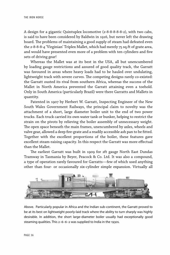
Above. Particularly popular in Africa and the Indian sub-continent, the Garratt proved to be at its best on lightweight poorly-laid track where the ability to turn sharply was highly desirable. In addition, the short large-diameter boiler usually had exceptionally good steaming qualities. This 2–6–6–2 was supplied to India in the 1930s.
T H E D E V E LO P M E N T O F S T E A M T R A C T I O N O N T H E R A I LWAY
PA G E 3 7
Garratts were built in Manchester, excepting a few made in France for service in Algeria and a handful built under licence in Spain. The largest was a solitary 4-8-4+4-8-4 Class 10 Ya, built for the USSR in 1932, which weighed 262.5 tons and had a nominal tractive effort of 78,700lb.
The largest steam engine to run in Britain was also a Garratt, LNER 2-8-8-2 Class U1 no. 2325, built in 1925 by Beyer, Peacock & Co. Ltd in Manchester. The solitary example was intended to bank 1100-ton coal trains on the incline from Wath to Penistone. Weighing 178 tons in working order, it had six 18½×26in cylinders which, with a boiler pressure of 180 lb/sq.in and driving wheels 4ft 8in in diameter, gave a nominal tractive effort of 72,940lb. No. 2325 was withdrawn for scrapping in the mid 1950s.
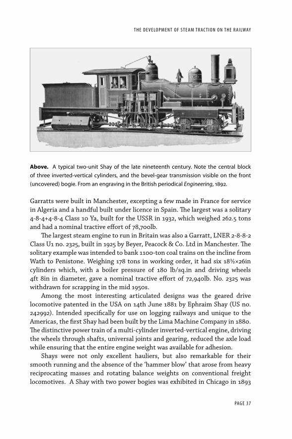
Among the most interesting articulated designs was the geared drive locomotive patented in the USA on 14th June 1881 by Ephraim Shay (US no. 242992). Intended specifically for use on logging railways and unique to the Americas, the first Shay had been built by the Lima Machine Company in 1880. The distinctive power train of a multi-cylinder inverted-vertical engine, driving the wheels through shafts, universal joints and gearing, reduced the axle load while ensuring that the entire engine weight was available for adhesion.
Shays were not only excellent hauliers, but also remarkable for their smooth running and the absence of the ‘hammer blow’ that arose from heavy reciprocating masses and rotating balance weights on conventional freight locomotives. A Shay with two power bogies was exhibited in Chicago in 1893
Above. A typical two-unit Shay of the late nineteenth century. Note the central block of three inverted-vertical cylinders, and the bevel-gear transmission visible on the front (uncovered) bogie. From an engraving in the British periodical Engineering, 1892.
T H E I R O N H O R S E
PA G E 3 8
and a three-bogie 0-4-4-4-0 (works no. 867) at St Louis in 1904. The latter had three 12×15in cylinders, three power bogies with 3ft diameter wheels, and weighed about 58 tons in working order. Overall length was 47ft 2¼in.
Even though speeds were very low, the standard 0-4-4-4-0 could haul 2800 tons on level track, 280 tons up a 1-in-30 gradient, and even 120 tons up 1-in-16. The minimum curve the bogies could take was just 100 feet. Amongst the smallest pattern was the 2ft gauge ‘10-2 Shay’, which had three 4½×8in cylinders. Though the diameter of the coupled wheels was only 22in, the engines could still pull 450-475 tons on level track. About 2770 Shays were made in Lima, Ohio, by the Lima Machine Works (1880-1931), and 33 of an adapted design by the Willamette Iron & Steel Works of Portland, Oregon, in 1922-9.
This made them the most popular of the geared locomotives manufactured in the USA. However, there were at least 1045 Climax locomotives and more than six hundred Heislers. The Climax was designed by Charles Scott but protected by patents granted to George Gilbert of Corry, Pennsylvania, and Rush Battles of Girard, Pennsylvania.* Designed by Charles Heisler of Dunkirk, New York, and protected by US Patent no. 482828 of 20th September 1892, Heisler locomotives were made until 1941 first by the Stearns Manufacturing Company and then by the Heisler Locomotive Works of Erie, Pennsylvania. A two-cylinder ‘V’-form engine drove a longitudinal shaft on the centre-line.
Fin de siècle: standardisation
Angered by opposition in Europe to the Second South African War, and widespread support for the Boer cause, Britain sent very few railway exhibits to the Paris exhibition of 1900. This caused adverse comment throughout the English-language engineering Press, though the tone was generally muted.
What was obvious from Paris, however, was that Britain was falling behind France and Germany in the design of railway engines. Yet the rapid spread of railways kept British manufacturing companies in constant work until the First World War. Excepting in Canada, where location and geography favoured
* The Climax had a tortuous history. The prototype had been made under the supervision of Charles Scott, partner in the Scott & Akin Company, loggers working in Spartansburg, Pennsylvania. However, US Patent 393896 was granted on 4th December 1888 to civil engineer George Gilbert, who had transformed the Scott locomotive to suit it to series production. The two-speed gearbox proved to be unsatisfactory, so a fixed-drive patented by Battles on 25th February 1890 (US no. 421894) was substituted. Longitudinal drive was replaced by transverse jackshaft and externally-mounted cylinders in 1890. Scott sued Climax, Gilbert and Battles for misrepresentation, obtaining a patent of his own (US no. 488484 of 20th December 1892) restoring the two-speed gearbox. About fifty locomotives of the perfected Scott design were then made by the Dunkirk Engineering Company.
T H E D E V E LO P M E N T O F S T E A M T R A C T I O N O N T H E R A I LWAY
PA G E 3 9
the importation of American-made motive power, Britain had built a sizeable worldwide export trade in railway equipment.
It was realised from the earliest days that demands for rolling stock could be satisfied only by some type of standardisation—Matthias Baldwin, for example, was making engines with standard templates and gauges as early as 1838. Though engineers such as William Stroudley strove to introduce standard components and fittings, and though some nineteenth-century British classes contained hundreds of similar-looking engines (the Ramsbottom DX Goods of the L&NWR eventually mustered 963), they were erected in batches and were rarely truly interchangeable. This was largely due to the high degree of hand finishing applied during assembly.
After 1900, therefore, efficiently-run locomotive manufacturers in the USA and Germany overhauled the British exporters by making huge numbers of locomotives which gained in ease of maintenance what they often lacked in style. The Baldwin Locomotive Works built its 17,000th railway engine in September 1899 and had constructed about sixty thousand when production ended in the 1950s: by comparison, the overall total of locomotives built in Britain (a difficult figure to assess accurately) has been estimated at only 140,000. Most of the latter had been made in Glasgow, Manchester and the ‘Railway Towns’, such as Crewe or Swindon, which had sprung virtually from nothing in the middle of the nineteenth century.
Standardisation enabled engines of the same type to be made by differing manufacturers, instead of each company championing its own methods; it reduced prime costs, pioneered the organisation of sub-contractors, and undoubtedly accelerated production. But, if pushed to extremes, it hamstrung independent thought and could be a ‘dead hand’ on development. The individuality of railway companies disappeared, standardisation being
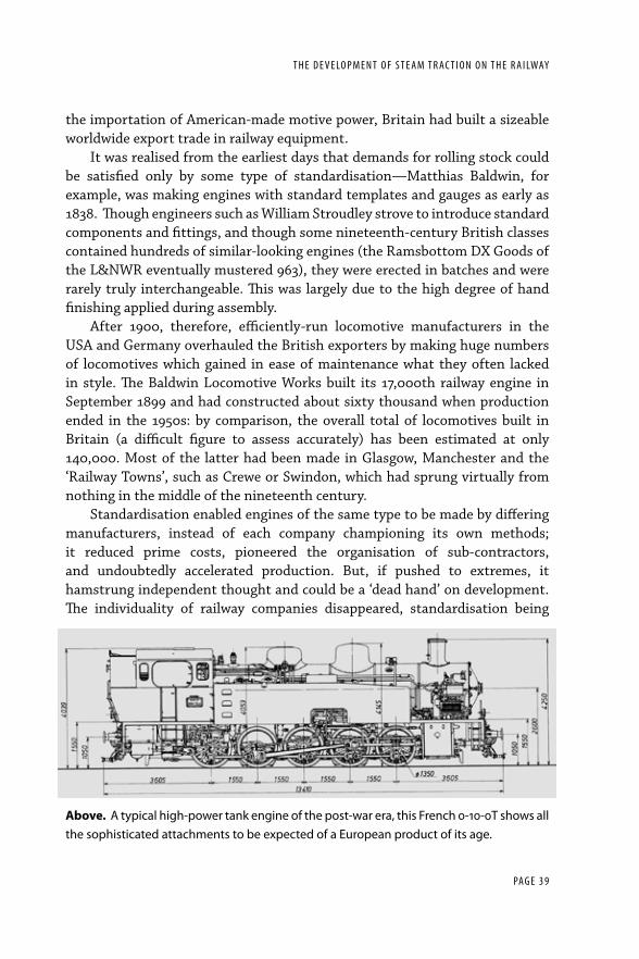
Above. A typical high-power tank engine of the post-war era, this French 0-10-0T shows all the sophisticated attachments to be expected of a European product of its age.
T H E I R O N H O R S E
PA G E 4 0
mirrored by the grouping of many smaller companies together, though quality and performance was often increased.
The quantities involved were often stupendous, as the Russians built about fourteen thousand 0-10-0s of near identical type, whilst there were more than 3800 P 8 class mixed traffic 4-6-0s (a pre-1918 Prussian design) in Germany. Almost without exception, locomotive classes standardised in this way were two-cylinder simple expansion machines offering great sturdiness but little in the way of sophistication.
HOW A LOCOMOTIVE WORKS
The steam locomotive of the 1950s differed very little from Stephenson’s Planet of 1830 as far as its basic characteristics were concerned.
Typical of the mid Victorian era was the Midland Railway 4-4-0s designed by Samuel Johnson, which replaced the rigid frame 2-4-0 popular with the designers of the 1860s. Johnson designed the first of his bogie engines for the
T H E D E V E LO P M E N T O F S T E A M T R A C T I O N O N T H E R A I LWAY
PA G E 4 1
Great Eastern Railway, where he had briefly been locomotive superintendent, but they were built under the supervision of his successor. The first ten ‘Midland Bogies’ were made by Kitson & Company of Leeds to handle passenger traffic of the Leicester & Manchester and Settle & Carlisle sections of the Midland Railway. Dating from 1876, they handled loads of 150 tons on gradients of 1-in-100 at 35mph, burning 26-30lb coal per mile and evaporating 7-8lb water per pound of coal. Kitson engines were supplemented by thirty built in the Derby
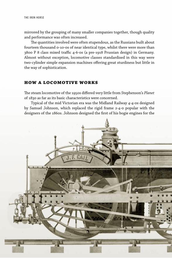
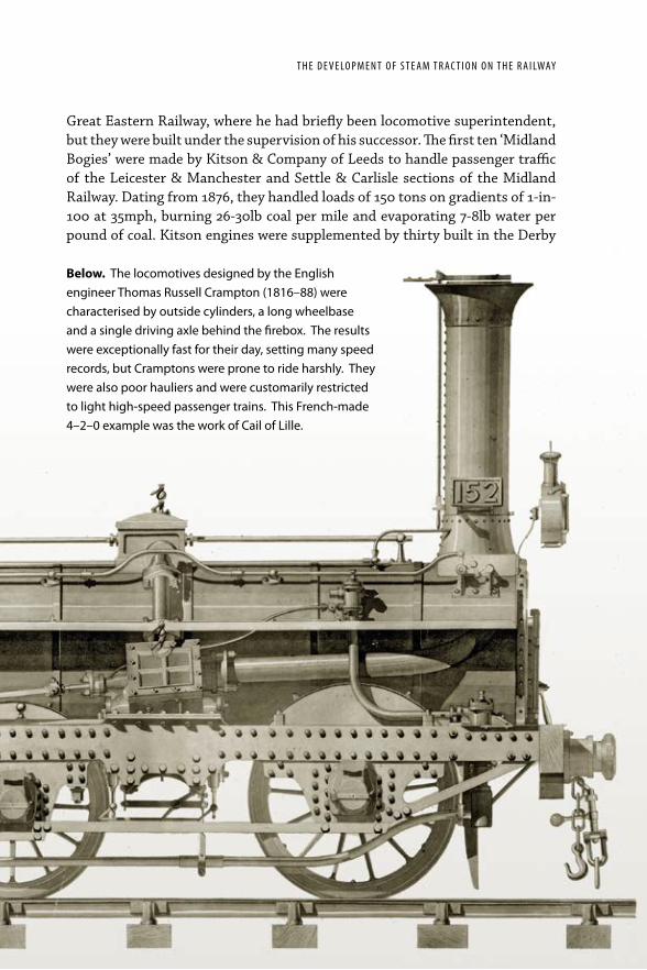
Below. The locomotives designed by the English engineer Thomas Russell Crampton (1816–88) were characterised by outside cylinders, a long wheelbase and a single driving axle behind the firebox. The results were exceptionally fast for their day, setting many speed records, but Cramptons were prone to ride harshly. They were also poor hauliers and were customarily restricted to light high-speed passenger trains. This French-made 4–2–0 example was the work of Cail of Lille.

T H E I R O N H O R S E
PA G E 4 2
railway works in 1882-3. These had 6ft 9in coupled wheels, 18×26in cylinders inside the plate frames, and weighed 75 tons 12 cwt in running order. The Johnson 4-4-0s of the 1882-3 series were described in great detail by Daniel Kinnear Clark in his book The Steam Engine. The power house of the engine was the boiler. This was basically a large-diameter cylinder, made of iron plates riveted together, closed at the rear by the firebox and at the front by

T H E D E V E LO P M E N T O F S T E A M T R A C T I O N O N T H E R A I LWAY
PA G E 4 3
the smokebox. Between the two ran 205 11/8in diameter fire tubes, nearly 11ft long, which connected the firebox with the front tube-plate. This tube plate formed the back edge of the smokebox and provided a restraint for the water which filled the intervening space. The boiler had a capacity of 152ft³, usually comprising 114ft³ of water (about 710 gallons) and 38ft³ of steam space. Coal was introduced periodically to the firebox, through a specially hinged door, to
T H E I R O N H O R S E
PA G E 4 4
burn with the assistance of a brick deflector arch. This was perfected in the 1860s—after much experimentation—to allow substitution of cheap coal for the expensive coke that had previously minimised smoke emissions. Hot smoke and gas rising from the fire passed from the firebox along the fire tubes and out into the chimney through the smokebox, helped by an air draught set up from fire to chimney.
The tubes radiated heat to the water in the boiler, until the temperature rose far enough for boiling to begin. Steam formed above the surface of the water, excessive pressure being prevented by the safety valve. The pressure in the boiler, in the case of the Johnson 4-4-0, was 140lb/in²; at this juncture, the boiling point of water (which varies with pressure) was 356ºF. When sufficient steam had been generated, the driver opened the regulator. This was a valve allowing steam to flow into the steam pipe, and was usually placed in a dome on the top of the boiler to isolate the regulator from the worst effects of turbulence at the surface of the water. This prevented excessive moisture reaching the cylinders (called ‘priming’).
Water had to be pumped back into the boiler from the tender tank, relying on two Gresham & Craven injectors. Patented in France in 1857-63 by Henri Giffard, an injector can use live steam to force water into the boiler even though great pressure was being maintained. Injectors replaced manually-operated force pumps, used on the earliest locomotives, and a selection of donkey pumps.
The steam pipe led forward inside the boiler casing, where it was surrounded by steam to prevent unnecessary loss of heat, until it entered the steam chest attached to the cylinder block. The block contained the driving piston and the valve mechanism. The valve admitted steam on alternate sides of the piston, pushing it backward and forward. The piston rod was connected to the driving axle by a sturdy strut—the connecting rod. If the cylinders were placed inside the frames (as in the case of the 4-4-0), the drive was to a crank formed in the axle itself; if the cylinders were outside the frames, crank pins in the centre disc of the wheels sufficed. By the time that steam reached the valve chests, its pressure had declined appreciably. It also contained a substantial quantity of moisture in suspension. Called ‘saturated steam’, this tended to condense in the cylinders and required the provision of cocks to drain it periodically.
The key to the operating process was provided by the valves. Flat faced slide valves had become universal by 1870, operating in conjunction with two admission ports (one at each end of the cylinder) and a central exhaust port. The valve was connected with the crankshaft by a rod and an eccentric (often spelled ‘excentric’ in the nineteenth century), which is simply a disc with an

T H E D E V E LO P M E N T O F S T E A M T R A C T I O N O N T H E R A I LWAY
PA G E 4 5
offset hole. A strap or collar running around the periphery of the eccentric disc was attached to the valve rod. As the crankshaft rotated, the eccentric moved the valve rod backward and forward, alternately admitting and exhausting steam from the opposing sides of the piston.
Steam exhausting from the cylinder was led up a central blast-pipe to emerge beneath the chimney. As the steam still had considerable pressure, its blast helped to drag smoke emanating from the fire tubes out of the chimney. This in turn improved the flow of air through the grate (by creating a partial vacuum in the smokebox) and helped the fire to draw. Adjustable jumper tops or blast-pipe rings were fitted to some engines to control the blast, which was sometimes so strong that small pieces of the fire were drawn through the fire tubes and ejected from the chimney with the smoke and steam.
The most important feature of the railway locomotive, and often a key distinguishing feature, lay in the style and construction of the valve gear. Valve gear regulated the flow of steam into the cylinders, and, when necessary, altered the position of the valves so that steam which would have flowed to one side of the piston was diverted to the other side. This reversed the motion of the piston, and allowed the locomotive to run backward.
By 1870, the system had been refined to ensure efficient use of steam by varying the point at which the admission of ‘live’ (full pressure) steam to the cylinder ceased. This was called the ‘point of cut-off’. Once a locomotive was running, cut-off could be adjusted to use less live steam, completing the piston stroke by expansion of the steam in the cylinder. The earliest forms of ‘gab’ valve gear (which could not be adjusted for cut off) had been superseded by the radial link gear designed in 1841-2 by William Williams and William Howe, then exploited by Robert Stephenson & Company of Newcastle upon Tyne from 1843 onward. This relied on a pair of eccentrics and a lifting link, operated by a reach rod in the cab, to re set the valve spindle.
Stephenson gear (as it soon came to be called) was simple and efficient, but had its rivals. Even in the nineteenth century, Allan’s straight link motion was popular, as it reduced vertical movement by simultaneously shifting both the straight link and the valve-rod die block; Joy’s gear abandoned eccentrics altogether in favour of separate anchor, jack and vibrating links. However, as locomotives became progressively more powerful and cranks became larger, the space inside the frames was increasingly restricted. A major disadvantage of Stephenson gear was the need for two eccentrics per cylinder, and a move was eventually made towards valve gear which lacked eccentrics altogether.
By far the most popular of the ‘non eccentric’ valve gear (in Britain and Europe at least) was patented in Belgium by Friedrich Fischer in October

T H E I R O N H O R S E
PA G E 4 6
1844, but is best known by the name of its designer: a machinist named Egide Walschaert (1820–1901).
It relied on a return crank attached to the crank pin, which drove a slotted link by way of an intermediate rod. The first locomotive with Walschaert’s gear to be made in Britain was an 0-4-4 ‘Single Fairlie’ built by the Avonside Engine Company of Bristol in 1878. This machine ran for a few years on the Swindon, Marlborough & Andover Railway, beginning in 1882, but Walschaert’s gear was very uncommon elsewhere in Britain prior to 1914—excepting in Ireland. Many Irish engines were supplied by the early British champion of the mechanism: Beyer, Peacock & Company of Manchester.