Embed Size (px)
Citation preview

The International Magnetics Association
An operating group of: The Transformer Association
1300 Sumner Avenue Cleveland, OH 44115 U.S.A. Telephone: (216) 241-7333 Facsimile: (216) 241-0105

FOREWORD
This standard on ferrite cores was developed by the engineering committee of the Soft Ferrite Division of the Magnetic Materials Producers Association. Several International Electrotechnical Commission documented recommendations have been included in this standard. The specific IEC publications that have been used in total or in part are: IEC 647 Dimensions for Magnetic Oxide Cores for use in Power Supplies (EC Cores) LEC 205 Calculation of effective parameters of magnetic piece parts ISO Recommendations: R370 was used in the conversion of toleranced dimensions from inches into millimeters and vice versa. This core standard is only an advisory document and its use or adaptation is entirely voluntary.
IMA WORKING GROUP MEMBERS
Adams Magnetic Products Company 888 Larch Ave. Elmhurst , IL 60126 (P) 800-275-6312 (F) 732-451-0339
Allstar Magnetics 6205 NE 63rd Street Vancouver, WA 98661 (P) 360-693-0213 (F) 360-693-0639
Dexter Magnetics 1050 Morse Ave. Elk Grove Village, IL 60007 (P) 847-956-1140 (F) 847-956-8205
Elna Magnetics 203 Malden Turnpike Saugerties, NY 12477 (P) 800-553-2870 (F) 845-247-0196
EPCOS 186 South Wood Ave. Iselin, NJ 08830 (P) 732-603-4300 (F) 732-906-4395
Fair-Rite Products 1 Commercial Row Wallkill, NY 12589 (P) 845-895-2058 (F) 845-895-2629
Ferroxcube 1200 Golden Key Circle Suite 233 El Paso, TX 79925 (P) 915-599-2616 (F) 915-599-2555
Magnetics 110 Delta Drive Pittsburgh, PA 15238 (P) 412-696-1333 (F) 412-696-1300
Micro Metals 5615 East LaPalma Ave. Anaheim, CA 92807 (P) 714-920-9400 (F) 714-970-0400
MTL Distribution 23167 Temescal Canyon Road Corona, CA 92883 (P) 951-270-0215 (F) 951-270-0245

National Magnetics Group 1210 Win Drive Bethlehem, PA 18017 (P) 610-867--7600 (F) 610-867-0200 TSC Ferrite International 39105 North Magnetics Blvd. Wadsworth, IL 60083 (P) 847-249-4900 (F) 847-249-4988
VAC Sales USA 2935 Dolphin Drive Suite 102 Elizabethtown, KY 42701 (P) 270-769-1333 (F) 270-765-3118

Standard Specifications for FERRITE U, E AND I CORES
1.0 SCOPE
This standard defines rectangular cross-section E cores, EC cores and ETD cores, their dimensions and tolerances. It also defines acceptance limits for variation in form, surface condition and general appearance common to U, E and I cores.
2.0 DIMENSIONS AND TOLERANCES 2.1 The physical dimensions of the standard series of EC cores shall be in accordance with Table 1.
For dimensional details see Figure 1
Table 1 DIMENSIONS OF EC CORES
SIZE TOL D1 D2 D4 H1 H2 W S R
mm in mm in mm in mm in mm in mm in mm in mm in mm in
EC MIN. 34 1.33 28 1.09 22 0.87 9.2 0.36 17.2 0.675 12 0.47 9.2 0.36 2.5 0.1 — —
MAX. 35 1.39 29 1.15 23 0.92 9.8 0.39 17.5 0.687 13 0.5 9.8 0.39 3 0.12 0.5 0.20
EC 41 MIN. 40 1.56 33 1.28 26 1.04 11.3 0.45 19.4 0.762 14 0.53 11.3 0.45 3 0.12 — —
MAX. 42 1.64 35 1.36 28 1.09 11.9 0.47 19.7 0.774 14 0.56 11.9 0.47 3.5 0.14 0.7 0.028
EC 52 MIN. 51 2 43 1.68 32 1.26 13.1 0.51 24.1 0.947 16 0.61 13.1 0.51 3.5 0.14 — —
MAX. 54 2.11 45 1.78 34 1.34 13.8 0.54 24.4 0.959 16 0.64 13.8 0.54 4 0.16 0.8 0.031
• EC 70 MIN. 68 2.69 58 2.28 43 1.71 16 0.63 34.4 1.352 22 0.88 16 0.63 4.5 0.18 — —
MAX. 72 2.82 61 2.41 46 1.8 16.8 0.66 34.7 1.364 23 0.91 16.8 0.66 5 0.2 1.0 0.039

2.2 The physical dimensions of E cores with rectangular cross-section shall be in accordance with Table 2. For dimensional details see Figure 2.
Table 2
DIMENSIONS OF E-CORES WITH RECTANGULAR CROSS-SECTION
SIZE TOL D1 D2 D3 H1 H2 w R1 R2
mm in mm in mm in mm in mm in mm in mm in mm in
E13/4 MIN. 12 0.48 8.9 0.35 3.4 0.13 6.3 0.25 4.5 0.177 3.4 0.13 — — — —
MAX. 13 0.52 9.5 0.37 3.7 0.15 6.5 0.26 4.8 0.189 3.7 0.15 1 0.039 0.3 0.01
E16/5 MIN. 16 0.61 11 0.45 4.4 0.17 7.9 0.31 5.7 0.224 4.3 0.17 — — — —
MAX 17 0.66 12 0.49 4.7 0.19 8.2 0.32 6.1 0.24 4.7 0.19 1 0.039 0.3 0.01
E20/6 MIN. 19 0.76 14 0.56 5.5 0.22 9.8 0.39 7 0.276 5.4 0.21 — — — —
MAX 21 0.82 15 0.58 5.9 0.23 10.2 0.4 7.4 0.291 5.9 0.23 1.5 0.059 0.4 0.02
E25/7 MIN. 24 0.96 18 0.69 7 0.28 12.3 0.48 8.7 0.343 6.9 0.27 — — — —
MAX 26 1.02 18 0.72 7.5 0.3 12.8 0.5 9.2 0.362 7.5 0.3 2 0.079 0.5 0.02
E3219 MIN. 31 1.23 23 0.89 8.9 0.35 15.8 0.62 11.2 0.441 8.8 0.35 — — — —
MAX. 33 1.3 24 0.93 9.5 0.37 16.4 0.65 11.8 0.465 9.5 0.37 2.5 0.098 0.6 0.02
E42/15 MIN. 41 1.63 30 1.16 12 0.46 20.8 0.82 14.8 0.583 15 0.58 — — — —
MAX. 43 1.69 31 1.21 12 0.48 21.2 0.83 15.5 0.61 15 0.6 2.5 .0.098 0.6 0.02
E42/20 MIN. 41 1.63 30 1.16 12 0.46 20.8 0.82 14.8 0.583 19 0.76 — — — —
MAX. 43 1.69 31 1.21 12 0.48 21.2 0.83 15.5 0.61 20 0.79 2.5 0.096 0.6 0.02
E55/21 MIN. 54 2.13 38 1.48 17 0.66 27.2 1.07 18.5 0.728 20 0.8 — — — —
MAX. 56 2.21 39 1.52 17 0.68 27.8 1.1 19.3 0.76 21 0.83 3 0.118 0.6 0.02
E55/25 MIN. 54 2.13 38 1.48 17 0.66 27.2 1.07 18.5 0.728 24 0.95 — — — —
MAX. 56 2.21 39 1.52 17 0.68 27.8 1.1 19.3 0.76 25 0.98 3 0.118 0.6 0.02
E65/27 MIN. 64 2.51 44 1.74 19 0.76 32.2 1.27 22.2 0.874 27 1.05 — — — —
MAX. 67 2.62 46 1.8 20 0.79 32.8 1.29 23 0.906 27 1.08 3 0.118 1 0.04
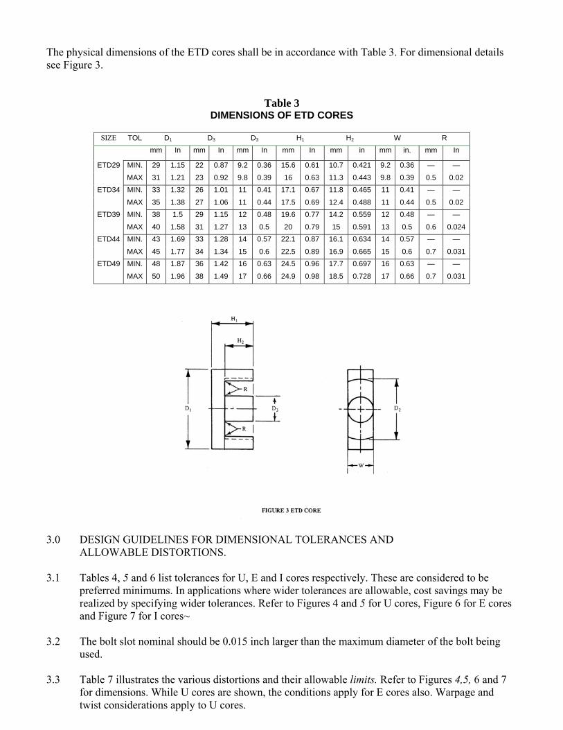
The physical dimensions of the ETD cores shall be in accordance with Table 3. For dimensional details see Figure 3.
Table 3
DIMENSIONS OF ETD CORES
SIZE TOL D1 D3 D3 H1 H2 W R
mm In mm In mm In mm In mm in mm in. mm In
ETD29 MIN. 29 1.15 22 0.87 9.2 0.36 15.6 0.61 10.7 0.421 9.2 0.36 — —
MAX 31 1.21 23 0.92 9.8 0.39 16 0.63 11.3 0.443 9.8 0.39 0.5 0.02 ETD34 MIN. 33 1.32 26 1.01 11 0.41 17.1 0.67 11.8 0.465 11 0.41 — —
MAX 35 1.38 27 1.06 11 0.44 17.5 0.69 12.4 0.488 11 0.44 0.5 0.02 ETD39 MIN. 38 1.5 29 1.15 12 0.48 19.6 0.77 14.2 0.559 12 0.48 — —
MAX 40 1.58 31 1.27 13 0.5 20 0.79 15 0.591 13 0.5 0.6 0.024ETD44 MIN. 43 1.69 33 1.28 14 0.57 22.1 0.87 16.1 0.634 14 0.57 — —
MAX 45 1.77 34 1.34 15 0.6 22.5 0.89 16.9 0.665 15 0.6 0.7 0.031ETD49 MIN. 48 1.87 36 1.42 16 0.63 24.5 0.96 17.7 0.697 16 0.63 — —
MAX 50 1.96 38 1.49 17 0.66 24.9 0.98 18.5 0.728 17 0.66 0.7 0.031
3.0 DESIGN GUIDELINES FOR DIMENSIONAL TOLERANCES AND ALLOWABLE DISTORTIONS.
3.1 Tables 4, 5 and 6 list tolerances for U, E and I cores respectively. These are considered to be
preferred minimums. In applications where wider tolerances are allowable, cost savings may be realized by specifying wider tolerances. Refer to Figures 4 and 5 for U cores, Figure 6 for E cores and Figure 7 for I cores~
3.2 The bolt slot nominal should be 0.015 inch larger than the maximum diameter of the bolt being
used. 3.3 Table 7 illustrates the various distortions and their allowable limits. Refer to Figures 4,5, 6 and 7
for dimensions. While U cores are shown, the conditions apply for E cores also. Warpage and twist considerations apply to U cores.

Table 4 DESIGN GUIDELINES FOR U CORES
DIMENSION TOLERANCE FIGURE
D1 measured at back of core ± .010 inch or ±2% whichever is greater 4 & 5
D2 ± .010 inch or ±3% whichever is greater 4 & 5
D3 measured at open end ± .010 inch or ±3% of D1 whichever is greater 4 & 5
D4 Reference only 4 H1 ± .010 inch or ± 1% whichever is greater 4 & 5
H2 ± .010 inch or ± 3% whichever is greater 4 & 5
WI ± .015 inch or ± 2% whichever Is greater 4 & 5
S ± .010 inch 4 & 5 (See para. 3.2)
DIMENSION TOLERANCE FIGURE
D1 ±3% 6 D2 ±3% 6 D3 ± .010 inch or ±2% whichever is
greater 6
H1 ± .010 inch or ± 1% whichever is greater
6
H2 ± .010 inch or ± 3% whichever is greater
6
W ± .015 inch or ±3% whichever is greater
6
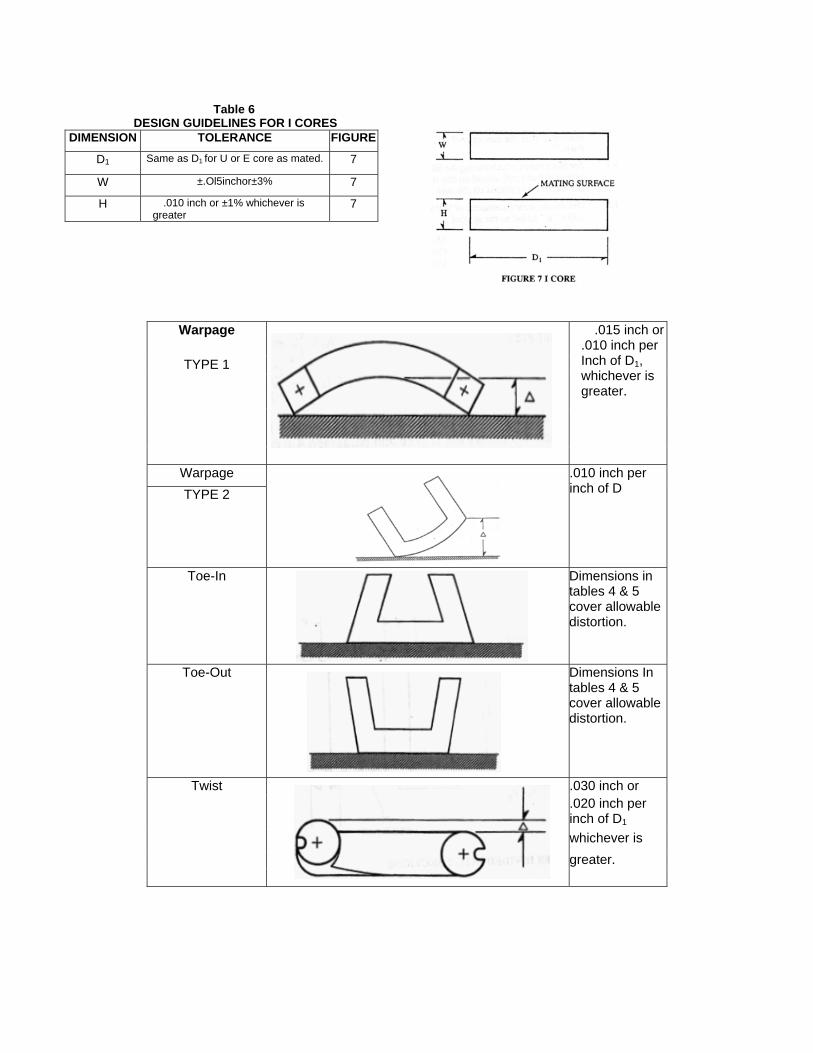
Table 6 DESIGN GUIDELINES FOR I CORESDIMENSION TOLERANCE FIGURE
D1 Same as D1 for U or E core as mated. 7
W ±.Ol5inchor±3% 7
H .010 inch or ±1% whichever is greater
7
Warpage
.015 inch or .010 inch per Inch of D1, whichever is greater.
TYPE 1
Warpage
.010 inch per inch of D TYPE 2
Toe-In Dimensions in tables 4 & 5 cover allowable distortion.
Toe-Out Dimensions In tables 4 & 5 cover allowable distortion.
Twist
.030 inch or
.020 inch per inch of D1 whichever is greater.

4.0 CALCULATION OF DIMENSIONAL PARAMETERS OF U, E, AND I CORES
The method used here is recommended for the calculation of the dimensional parameters of U, E and I cores and is consistent with the concepts of IEC Publication 205, “Calculation of Effective Parameters of Magnetic Piece Parts.
4. 1 For this method of calculating the dimensional parameters of cores, the core set is substituted by an ideal toroidal core such that a coil wound on that toroid would give exactly the same electrical performance as a coil with some number of turns placed on the core set.
4.2 The dimensional parameters of that substitute toroid are called effective parameters. These are indicated by
the suffix “e” added to the symbol. Magnetic path length Ie mm
Cross-sectional area Ae mm2 Core volume Ve mm3
4.3 For the purpose of the calculation of the dimensional parameters, the closed magnetic circuit of the core set
is divided into five sections. The core constants for the total magnetic circuit of the core set are:
C1 =Σ le/Ae mm-1 & C2 =Σ le/ae2 mm-3
e From these core constants the effective dimensional core parameters can be calculated. Magnetic path length Ie = C1
2 /C2 mm Cross-sectional area Ae = C1 /C2 mm2 Core volume Ve= Ie Ae = C1
3 /C22 mm3
4.4 For each of the five sections of the magnetic circuit of a core set, the magnetic path length and cross-
sectional area
has to be determined: Paragraph 4.5 covers the U core and paragraph 4.6 covers the E core. 5
C1 =Σ l1/A1 mm-1 1
C2 =Σ l1/A12 mm-3
1 4.5 U Cores of rectangular or round section.
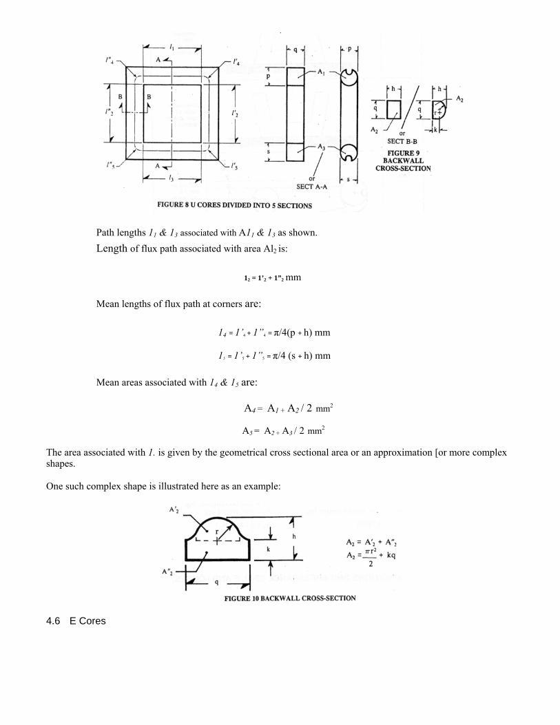
Path lengths 11 & 13 associated with A11 & 13 as shown. Length of flux path associated with area Al2 is:
12 = 1’2 + 1”2 mm
Mean lengths of flux path at corners are:
14 = 1’4 + 1”4 = π/4(p + h) mm
15 = 1’5 + 1”5 = π/4 (s + h) mm
Mean areas associated with 14 & 15 are:
A4 = A1 + A2 / 2 mm2
A5 = A2 + A3 / 2 mm2 The area associated with 1. is given by the geometrical cross sectional area or an approximation [or more complex shapes. One such complex shape is illustrated here as an example:
4.6 E Cores

PATH LENGTHS (mm) AREAS (mm2)
11 & 13 as shown A1 = A’1 + A”1 12 = 1’2 + 1”2 A1 = 2qp rectangular leg 14 = 1’4 + 1”4 A1 = 2qp – Πa2/2 E C Core 14 = Π/4 (p + h) A2 = A’2 + A”2 15 = 1’5 + 1”4 A2 = 2qh 15 = Π/4 (s + h) rectangular center leg A3 = A’3 + A”3 15 = Π/4 (2s1 + h) round center leg A3 = 2sq rectangular leg
Where s1 = O.5959s A3 = Π s2 round leg A4 = 1/2(A1 + A2)
A5 = 1/2(A2 + A3) 5.0 SURFACE CONDITIONS AND APPEARANCE OF U, E AND I CORES.
5.1 Cleanliness All mating surfaces of the core should be free of dirt or any other foreign matter. (Any stain, discoloration or surface crazing that does not interfere mechanically or electrically is allowed.)
5.2 Visual appearance of U, E and I cores.
5.2.1 The reference dimension is the smallest dimension of the surface under consideration. In the case of a
round leg, the diameter shall be the reference dimension for the cylindrical surface.
5.2.2 The largest dimension of a chip is the one to be used for the limit comparison.
5.2.3 A chip or a crack which extends over more than one surface shall be counted as one such defect.

5.2.4 Bolt slots or clamping notches shall be considered as part of the surface they are on.
5.2.5 The surface of a recessed leg shall be considered as a mating surface.
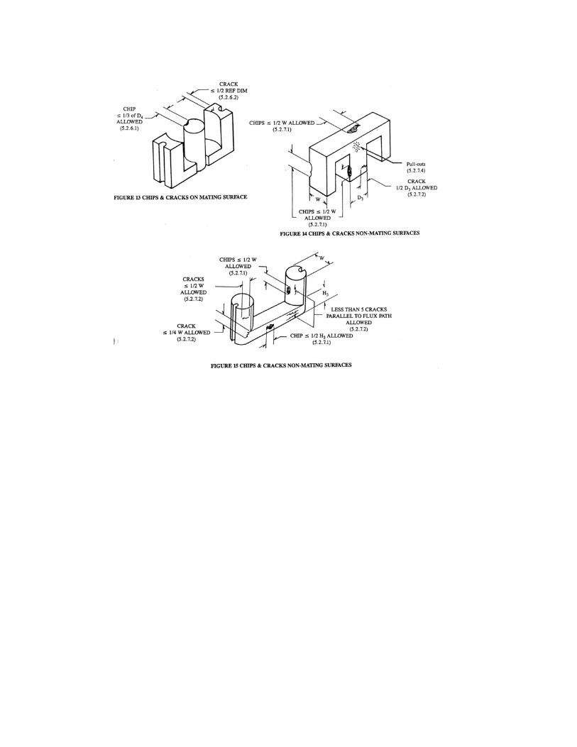
5.2.6 Mating Surfaces (See Figure 13).
5.2.6.1 Chips with their largest dimension less than or equal to 1/3 of the reference dimension are acceptable.
The total number of such chips acceptable shall not exceed:
2 for U core
3 for E core
2 for I core 5.2.6.2 Cracks that are less than 1/2 of the reference dimension are allowed. The sum total of crack lengths for ~
each surface shall not exceed 1/2 the reference dimension.
5.2.6.3 ‘Pits and surface voids are to be considered as chips, defined in Paragraph 5.2.6.1.
5.2.7 All non-mating Surfaces. (See Figures 14 and [5).
5.2.7.1 Chips with their largest dimension less than or equal to 1/2 of the reference dimension are allowed. The
maximum number of such chips per core is:
7—U core
5—E core
2—I core
5.2.7.2 Cracks, other than corner cracks perpendicular to the flux path, shall not exceed 1/2 of the reference dimension. The total number of such cracks shall not exceed 3. Cracks parallel to the flux path are acceptable. The total number of such cracks shall not exceed 5.
Corner cracks shall not exceed 1/4 of the reference dimension. The total number of such cracks shall not exceed 2. Pits and surface voids are to be considered as chips defined in Paragraph 5.2.7.1.
Pull-outs (See Figure 14). Die pull-outs on a core surface that are less than 25% of the surface area are acceptable.