Embed Size (px)
Citation preview
THE INSTITUTION OF ENGINEERS OF IRELAND
GALWAY CITY WASTEWATER TREATMENT PLANT
DESIGN AND CONSTRUCTION ASPECTS
Mr. M.J. Edger, BSc Eng FIEI FCIWEMDirector P.H. McCarthy & Partners, Consulting Engineers
Mr. S. Murdock, BEng (Hons)Associate Director P.H. McCarthy & Partners, Consulting Engineers
Paper presented to the Institution of Engineers of IrelandJoint Civil and Water & Environmental Divisions, 7th April, 2003
Synopsis
The Galway City Wastewater Treatment Plant was designed to meet the requirements of the Urban Wastewater Treatment Directiveand to ensure that the quality of the bathing and shellfish waters in Galway Bay is not compromised by discharges from the plant.
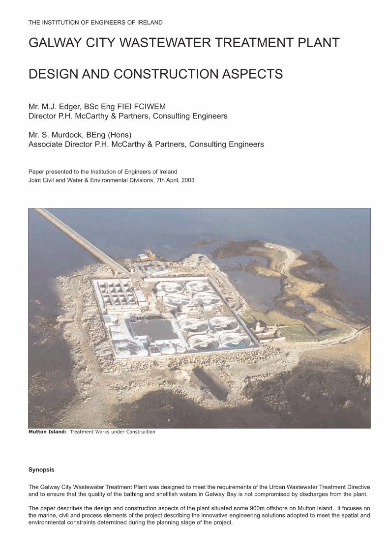
The paper describes the design and construction aspects of the plant situated some 900m offshore on Mutton Island. It focuses onthe marine, civil and process elements of the project describing the innovative engineering solutions adopted to meet the spatial andenvironmental constraints determined during the planning stage of the project.
Mutton Island: Treatment Works under Construction

1.0 BACKGROUND
1.1 Overview
The Galway City Wastewater TreatmentPlant has been designed to meet therequirements of the Urban WastewaterTreatment Directive 91/271/EEC, enactedinto Irish Law by SI 419 of 1994, and toensure that the water quality at thedesignated bathing beaches ofSilverstrand near Barna, SalthillPromenade including Grattan Road andBallylaughaun Beach at Renmore alongwith the shellfish waters of New Harbourand Mweeloon Bay are not compromisedby the discharges from the plant.
An Environmental Impact Statement(EIS) for the scheme was prepared byP.H.McCarthy & Partners in 1992 and theMinister for the Environment confirmedthe Environmental Impact Assessment(EIA) in May 1993. Following local objectionsthe proposed scheme was the subject ofHigh Court and Supreme Court actions.These proceedings ended in March 1998with the Courts finding in favour of thescheme.
It was originally planned that the plantwould be constructed in two stages. Thefirst stage would treat a population equivalentof 67,800 and the second stage 91,600.However, given the unprecedented rateof growth in the catchment over the periodthat elapsed between the preparation ofthe EIS and the detailed design stage itwas decided to design and construct aplant capable of treating flows from apopulation equivalent of 91,600, themaximum permitted under the EIA. Thisgrowth rate was later confirmed by a flowand load survey.
1.2 The Scheme Contracts
The scheme comprises of four distinctcontracts as follows:
Contract 1 - Causeway ConstructionContract 2 - Site InvestigationsContract 3 - Wastewater Treatment
Plant and Sea Outfall- Civil Work
Contract 4 - Wastewater TreatmentPlant and Sea Outfall- Mechanical & Electrical
Installation
Contract 1, which included the accesscauseway to the island and incorporatedthe 1800mm diameter trunk sewer to theplant commenced in April 1998 inadvance of Contract 3 and Contract 4.
Contract 2, the site investigation contract,commenced in January 1999 to providethe geotechnical information required tofinalise the civil engineering design.
1.3 Scope of this Paper
This Paper focuses on the design andconstruction of the marine, civil andprocess engineering elements of the projectand how these were developed within thespatial and environmental constraints setout in the EIA and integrated into theoverall project.
2.0 DESIGN
In this section the key issues relating tothe design of the scheme are discussed.
2.1 Causeway to Mutton Island
The treatment works site is located onMutton Island some 900m off-shore fromSouth Park on the southern fringes of thecity. A causeway was required to providepermanent access to the treatmentworks. It was also necessary to constructa 1800mm diameter trunk sewer to theisland. This sewer was designed to provideon-line storage to the inlet pumping stationat the treatment works and limit the spillfrequency at the combined sewer overflowsdischarging to the River Corrib.
A rock core causeway was designed witha top level of 6.3m O.D. (Poolbeg). Thislevel approximates to the level of theforeshore at South Park and was selectedto mitigate the visual intrusion of thecauseway. The causeway incorporatesthe trunk sewer and the utility services forthe treatment plant. The top of the causewayis 1.4m above MHWST and wasdesigned for overtopping at times of highseas. An analysis based on MHWSTlevel and local wind speeds predicted thatthe causeway could be overtopped forperiods on a maximum of 58 days perannum.
Mathematical wave modelling indicatedthat the causeway should be designed fora sea state with a double peaked spectrawith a significant height of 3.1m. Thewaves were predicted to be steep tobreaking with expected maximum waveheights of 5m.
Two options were considered for revetmentprotection. These included conventionalrock armour and the use of precast concrete
hollow core Shepard Hill EnergyDissipation (SHED) units. Analysis usingthe Hudson Formula predicted that inorder to dissipate wave energy the revetmentshould be constructed with 17 tonnearmour with a 1 in 2.5 side slope or using2 tonne SHEDs with a 1 in 1.5 side slopeThe SHED units, which were model testedat University College Cork and found tobe stable when subjected to waves up to5m, were incorporated into the design.
The final causeway design is shown onFigure 1. Precast concrete toe units weredesigned to hold the SHED units in placeand the construction was secured with asystem of steel tie rods. The final roadwidth selected was 4.5m and a footpathwas constructed to facilitate publicaccess, provide a promenade andenhance the local amenity value of thecauseway post construction.
2.2 Site Investigations
A major site investigation contract wasawarded to establish the ground conditionson the site of the treatment works and theroute of the sea outfall.
The investigations were carried out byFugro Ltd. in 1999 and included 36 No.land based boreholes and 9 No. marineboreholes. Drilling was by shell andauger and rotary core drilling to depths of11m and trial pits were excavated acrossthe site. Piezometer and stand pipeswere installed and Packer tests and pumptests carried out to determine rockpermeabilities. Seismic refraction andelectromagnetic surveys were used tointerpret conditions between boreholeand trial pit locations.
Trial blasts were carried out in both theland and marine environments and vibrationswere monitored.
The investigations indicated that the solidunderlying geology comprised of two rocktypes; an igneous (plagioclase and microgranite) and a metamorphic (generallyamphibolite grade Migmatite). Both wereclassified as strong to extremely strong.
The rocks were overlaid by superficialdeposits of sandy clayey gravel, peatyclay and dense boulders.
WEST SIDEWEST SIDE EAST SIDEEAST SIDE
1.51.511
STEEL TIE RODSTEEL TIE ROD
GEOTEXTILEGEOTEXTILE
ROCKFILLROCKFILLCORECORE
SHED UNITSSHED UNITS
1829 dia. PIPE1829 dia. PIPE
ROAD SLABROAD SLAB
Figure 1: Final Causeway Design

The investigations concluded that the rockexcavation was likely to be too difficult formechanical plant and recommendedblasting to fragment the rock.
Fawley Laboratories research shows thatsound levels which cause behaviouralchange in the marine environment lie inthe range 160-180 dB. From the resultsof blasting trials and using the scaleddistance techniques for a 25kg chargeweight it was estimated that the affectedrange would be 475m to 3500m from theblast.
The piezometer measurements andpumping tests all indicated that rapidwater ingress can occur as the tide risesabove the level of the overlying marinesand and gravel deposits.
2.3 Sea Wall and Rock ArmourRevetment
Mutton Island is a low lying rocky irregularshaped island. The highest natural landlevel is 7.96m O.D. The site available forthe treatment works (168m x 138m) hadan average ground level of 5.0m O.D.which is marginally above MHWST. Thesite had to be raised and protected fromthe sea with overtopping controlled to levelsthat are acceptable for safe operation ofthe plant.
Kirk McClure & Morton ConsultingEngineers were commissioned to extendthe model prepared for the design of thecauseway and to assess the wave climateat the treatment works site.
Mike 21 Near-Shore and the Mike 21PMS Spectral Wind wave modules wereused to undertake wave transformationalmodelling for various storm wind directionsand return periods.
Rock armour stability was modelled usingcomputational Van der Meer equations.
The major constraint on the design of thecoastal protection for the treatment workssite was the limited area available. Theforeshore licence obtained from theDepartment of the Marine and NaturalResources provided an area 1 ha. Thisplaced a limit on the revetment crestwidth and side slope that could be adopted.The site could not be adequately protectedwith a conventional rock armour revetment.
The preferred design was a wave reflectingsea wall constructed to a level of 9.5mO.D. and a rock armour revetment to alevel of 7.5m O.D. with a berm width of4.0m and a side slope of 1 in 1.5. Thewave wall and berm details are shown onFigure 2.
Modelling indicated that 13.5 tonne primaryarmour was required and that meanovertopping in a 1 in 5 year return stormwould be 1.12 x 10⁻⁴ m³/s/m. Overtopping would be limited to 2% of waves. Thedesign provides adequate protectionagainst mean overtopping discharges.
To resist the moments induced by waveaction the sea wall was designed as apropped cantilever retaining wall surroundingthe site. Founded on rock, the wall waspropped at pavement level (circa 7.0mO.D.) by the pavement structure whichtransfers the horizontal forces to verticalbuttresses (elements of the processunits) and thereby to rock. The pavementstructure varied from a 500mm deep slabadjacent to the aeration lanes to 1.5mdeep beam at the location of the primarydigesters, the most exposed area of thesite.
2.4 Process Design Overview
The process design criteria is set out inTable 1 below and schematically onFigure 5 below. To meet the requirementsof the Urban Wastewater TreatmentDirective the final effluent water quality asa 95 percentile has to meet BOD 25 mg/l,TSS 35mg/l and COD 125 mg/l standards.While the receiving waters have not beendesignated sensitive under SI 254 of 2001it was decided at design stage to use thenitrification/ partial denitrification availablein the treatment process to limit NH4concentrations in the discharges to lessthan 5 mg/l.
7.00m
9.50m
FINISHED GROUND LEVEL
EXISTING GROUND LEVEL
Fi 2 SEA WALL DETAIL
ROCK LEVEL
5.00m
2.55m
5000
1
1
GEOTEXTILE 603g/m²
7.50m
3500
3500
1430
600
FILTER ROCK NOMINAL SIZE 900mm
TOE PROTECTION
PROP SLAB (THICKNESS VARIES FROM 500 - 1500mm)
13.5t PRIMARY ARMOUR
MHWST 4.90m
Figure 2: Wave Wall and Revetment Detail
PicketFence
Thickener
DigesterBufferTank
PasteurisationPlant
SecondaryDigester
GasHolder
RBI
RBI
SecondarySludge
Thickeners
Aeration Plant
Air Blowers
PrimarySettlement TanksInlet
Screw PumpsFine
Sceens
DewateringPlant
Sludge Skips
Digestors
Outfall
Outfall Pumps
FinalSettlement Tanks
SecondarySludge Removal
Gas Flare
PrimaryEffluent
PrimarySludgeRemoval
IntermediateScrew Pumps
PROCESSPROCESSFLOWFLOW
DIAGRAMDIAGRAM
FinalEffluent
IncomingFlow
GritRemoval
Figure 3: Process Flow Diagram
A number of process options wereinvestigated at the time of the preliminaryreport studies. These included conventionalactivated sludge, extended aeration andthe emerging technologies of Vitox,UNOX, Deep Shaft, SBAF and the A/B.Based on technical and economicevaluations the conventional activatedsludge process with sludge digestion anddewatering was selected as the preferredtreatment process and was fully prescribedin the EIS.
The preferred disposal route for sludgearising at the works was disposal onagricultural land. During the post-tenderpre-contract stage sludge pasteurisationwas added to the process to comply withthe DoELG Circulars L6/94 and L9/99relating to disposal of biosolids to agriculturalland.
2.5 Pumping Plant
To ensure that the existing lighthouseremained the prominent feature on theisland the building height on the treatmentworks site was restricted. It was thereforenecessary to provide inlet, intermediateand outfall pumping at the plant. Thisresulted in a low static lift with high flowrates. These conditions were not suitedto conventional pumping as control difficultiesare experienced due to the minimalchange in total head with varying flows.
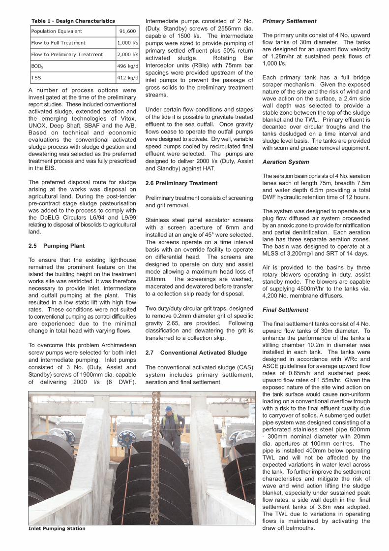
To overcome this problem Archimedeanscrew pumps were selected for both inletand intermediate pumping. Inlet pumpsconsisted of 3 No. (Duty, Assist andStandby) screws of 1900mm dia. capableof delivering 2000 l/s (6 DWF).
Intermediate pumps consisted of 2 No.(Duty, Standby) screws of 2555mm dia.capable of 1500 l/s. The intermediatepumps were sized to provide pumping ofprimary settled effluent plus 50% returnactivated sludge. Rotating BarInterceptor units (RBIs) with 75mm barspacings were provided upstream of theinlet pumps to prevent the passage ofgross solids to the preliminary treatmentstreams.
Under certain flow conditions and stagesof the tide it is possible to gravitate treatedeffluent to the sea outfall. Once gravityflows cease to operate the outfall pumpswere designed to activate. Dry well, variablespeed pumps cooled by recirculated finaleffluent were selected. The pumps aredesigned to deliver 2000 l/s (Duty, Assistand Standby) against HAT.
2.6 Preliminary Treatment
Preliminary treatment consists of screeningand grit removal.
Stainless steel panel escalator screenswith a screen aperture of 6mm andinstalled at an angle of 45° were selected.The screens operate on a time intervalbasis with an override facility to operateon differential head. The screens aredesigned to operate on duty and assistmode allowing a maximum head loss of200mm. The screenings are washed,macerated and dewatered before transferto a collection skip ready for disposal.
Two duty/duty circular grit traps, designedto remove 0.2mm diameter grit of specificgravity 2.65, are provided. Followingclassification and dewatering the grit istransferred to a collection skip.
2.7 Conventional Activated Sludge
The conventional activated sludge (CAS)system includes primary settlement,aeration and final settlement.
Primary Settlement
The primary units consist of 4 No. upwardflow tanks of 30m diameter. The tanksare designed for an upward flow velocityof 1.28m/hr at sustained peak flows of1,000 l/s.
Each primary tank has a full bridgescraper mechanism. Given the exposednature of the site and the risk of wind andwave action on the surface, a 2.4m sidewall depth was selected to provide astable zone between the top of the sludgeblanket and the TWL. Primary effluent isdecanted over circular troughs and thetanks desludged on a time interval andsludge level basis. The tanks are providedwith scum and grease removal equipment.
Aeration System
The aeration basin consists of 4 No. aerationlanes each of length 75m, breadth 7.5mand water depth 6.5m providing a totalDWF hydraulic retention time of 12 hours.
The system was designed to operate as aplug flow diffused air system proceededby an anoxic zone to provide for nitrificationand partial denitrification. Each aerationlane has three separate aeration zones.The basin was designed to operate at aMLSS of 3,200mg/l and SRT of 14 days.
Air is provided to the basins by threerotary blowers operating in duty, assiststandby mode. The blowers are capableof supplying 4500m³/hr to the tanks via.4,200 No. membrane diffusers.
Final Settlement
The final settlement tanks consist of 4 No.upward flow tanks of 30m diameter. Toenhance the performance of the tanks astilling chamber 10.2m in diameter wasinstalled in each tank. The tanks weredesigned in accordance with WRc andASCE guidelines for average upward flowrates of 0.85m/h and sustained peakupward flow rates of 1.55m/hr. Given theexposed nature of the site wind action onthe tank surface would cause non-uniformloading on a conventional overflow troughwith a risk to the final effluent quality dueto carryover of solids. A submerged outletpipe system was designed consisting of aperforated stainless steel pipe 600mm- 300mm nominal diameter with 20mmdia. apertures at 100mm centres. Thepipe is installed 400mm below operatingTWL and will not be affected by theexpected variations in water level acrossthe tank. To further improve the settlementcharacteristics and mitigate the risk ofwave and wind action lifting the sludgeblanket, especially under sustained peakflow rates, a side wall depth in the finalsettlement tanks of 3.8m was adopted.The TWL due to variations in operatingflows is maintained by activating thedraw off belmouths.
Table 1 - Design Characteristics
Population Equivalent 91,600
Flow to Full Treatment 1,000 l/s
Flow to Preliminary Treatment 2,000 l/s
BOD5 496 kg/d
TSS 412 kg/d
Inlet Pumping Station

2.8 Sludge Treatment
The sludge treatment process consists ofthickening, pasteurisation, anaerobicdigestion and dewatering. The processalso includes gas production, storage andutilisation.
Sludge Thickening
Separate thickening of the primary andsecondary sludges was incorporated inthe process design. Picket fence thickenersdesigned in accordance with WRcGuidelines were used for the primarysludges. Given the spatial constraints onthe site, drum thickeners were adopted asthe method of secondary sludge thickening.Polymer dosing of secondary sludge isrequired to aid thickening. The designeddry solids content of the thickenedsludges was 6%.
Pasteurisation Unit
To comply with current national requirementsrelating to disposal of biosolids to agriculturalland a pasteurisation stage was added tothe process post-tender and pre-contractaward. The proprietary plant selectedwas that designed and installed byPassavant Roediger (Germany) and consistsof two sets of heat exchangers, a reactorvessel, hot water boiler and ancillaryequipment. Mixed sludges pumped fromthe buffer storage tank pass through theheat exchangers to raise the temperatureof the sludge to in excess of 70°C. Theheated sludge remains in the reactor for aminimum of 1 hour to achieve therequired pathogen kill. The secondcold/hot heat exchanger is used to reducethe temperature of the pasteurisedsludge to the range 33°C - 38°C priorto delivery of the pasteurised sludge tothe anaerobic digestors.
Anaerobic Digestors
The digestors consist of 3 No. reinforcedconcrete tanks each 12m diameter andwith a cylinder wall height of 7.9m.
The digestors, which are mechanicallymixed using vertical shaft mixers, havebeen designed to provide a hydraulicretention time (HRT) of 19 days. Thepasteurised sludge introduced at atemperature between 33 and 38°C ismaintained at this temperature byrecirculating the sludge through a heatexchanger. Dual fuel boilers, which canoperate on biogas or diesel, heat therecirculating water used in the heatexchanger.
Sludge Dewatering Plant
Duty/standby centrifuges were designedto dewater sludge to a minimum drysolids content of 25% and a target drysolids of 30% while achieving optimumpolyelectrolyte consumption. Dewateredcake is removed via sludge cake transferpumps to enclosed skips ready forremoval and disposal.
Gas Production, Storageand Utilisation
It was calculated that, at full designcapacity, the anaerobic process will producesome 2,500m³/d of gas. This gas will beused to maintain the heat balance inthe pasteurisation/digestion process.
A double skinned membrane gas holderproviding 4 hour gas storage at maximumproduction was provided along with a lowlevel gas burner capable of burning100m³/hr.
2.9 Odour Control
The EIA required odour control on allvented discharges from the plant. Twooptions were considered, biofiltration andchemical treatment. An anticipated H2Sconcentration of 37 mg/l and a volumetricair flow rate 17,300m³/h was the basis ofthe design. Following detailed evaluationof design alternatives and given the spatialconstraints of the site, two duty biofiltrationunits containing organic media wereselected as the best technical andeconomical option. A catalytic iron filterwas introduced upstream of the odourbed to reduce H2S levels and prolongfilter bed life.
2.10 Electrical Distribution
Given the strategic importance of thetreatment works it was necessary toensure that the power supply and distributionsystem was secure under all eventualities,that it included an appropriate level ofredundancy and that standby equipmentwas provided.
Electrical power is supplied to the works at10KV 3 phase 3 wire 50 Hz isolated neutralvia. two dedicated underground cableradial feeds to provide forward and back-up supply. All equipment connected tothe ESB 10KV network was rated for afuture network upgrade to 20KV. Thisconstitutes a secure supply, with a maximumpredicted outage of six hours. Primaryprotection is by standard SF6 breakersfeeding two full rated indoor dry typetransformers at 2.5MVA, giving 100%redundancy, and then offloading to themain distribution board.
Continuity of supply to the works underpower outages is ensured by the provisionof a standby generator rated at 2.2MVA.This set will be configured for synchronousoperation allowing a peak lopping operationstrategy.Pasteurisation Unit: Heat Exchanger
Final Settlement Tank: Diffusers and Submerged Outlet

Motor control centres were designated foreight defined process plant areas toinclude all variable speed drives and softstarters as required. A comprehensivepower monitoring and control scheme,integrated with the SCADA system, wasincluded to optimise the performance ofthe system.
2.11 PLC and SCADA Control
Plant data exchange across the processareas was designed to operate by interPLC (peer to peer) communication link.The system configuration adopted wasthe client server model with supervisorrun time and back up PCs, peripheralsand operator stations with all PLCs on anindustrial ethernet LAN. Operator stationsare industrial flat screen LCD display PCsintegrated with the MCCs allowing fullSCADA access capability to all processes(subject to password level protection).
The network was implemented withincreased security against lightning strikesand mains borne electrical disturbances.The full graphic and visual process onlinecapability of Intouch software was exploitedobviating the need for a hardwired mimic.The requirements for control of the variousitems of plant and process streams weredefined in the specification as a UserRequirement Specification (URS). Thisand the summary signal and softwarehandling schedule was the entry level forthe contractor to produce a full FunctionalDesign Specification (FDS) and softwareengineering design.
2.12 Water Quality Modellingand Sea Outfall Design
As part of the site investigation amathematical model study to assess thehydraulic and water quality impacts of theoutfall discharges from the works wascarried out in 1999. The fieldwork whichincluded a bathymetric survey, currentmetering, drogue tracking and a dyedispersion survey was implemented byIrish Hydrodata Ltd. A two dimensionaldepth averaged hydrodynamic and waterquality model at North Galway Bay wasdeveloped by Mr. A. Cawley of theDepartment of Engineering Hydrology,NUI Galway and validated against theresults of the field surveys.
The model predicted that, with dischargesfrom an outfall located 400m off the southcoast of the island, the EC guideline faecalcoliform limit of 100 No./100ml at 80%compliance required as a Blue Flag standardwould be met at the designated bathingbeaches and that the shellfish waters inSouth Galway Bay would not be compromisedby the outfall discharges.
To maximise initial dilution prior to plumesurfacing it was necessary to design anoutfall diffuser that met both the hydraulicand near field mixing requirements.
The design was carried out with the aid ofLOOP and CORMIX computer programmes.
The favoured diffuser configurationincorporated a 100m length of diffuserwith 10 riser single 200mm diameterTideflex port diffusers. The outfall pipetapered from 900mm to 1000mm nominaldiameter over the length of the diffuser.Concrete chambers were designed toprotect the diffuser risers and Tideflexvalves. A mattress of 150mm nominalstone was installed over the diffuser areato prevent scour of the sea bed duringoutfall operation.
3.0 PROCUREMENT
A traditional contract procurement routewas adopted for the project. Accordingly,all contracts works were fully designedand detailed by the engineer. Followingopen tendering the contracts were awardedbased on admeasurement rules
3.1 Conditions of Contract
The IEI Conditions of Contract for use inconnection with Works of CivilEngineering Construction Third Edition1980 (Revised and Reprinted October1990) and amended in accordance withthe DoELGs CONDOC was used forContracts 1, 2 and 3.
The MF/1 (Rev. 3) Conditions of Contractfor Supply of Electrical, Electronic orMechanical Plant - With Erection 1988Edition and amended in accordance withthe DoELG's CONDOC was adopted forContract 4.
3.2 Tendering Proceduresand Finances
The tendering process followed EU andnational procedures for works contractsand the scheme was financed by the IrishGovernment and formed part of thecurrent National Development Plan.
3.3 Contract Award
Following open tender procedures thetenders were awarded as follows:
Contract 1 Ascon Ltd.Contract 2 Fugro Ltd.Contract 3 Ascon Ltd.Contract 4 Jones Environmental
(Ireland) Ltd.
4.0 CONSTRUCTION STAGE
In this section the key issues relating toconstruction, including a number ofmodifications to aid buildability andreduce programme risks agreed betweenthe Contractor and the Engineer post-tender,are described.
4.1 Causeway Construction
During the causeway construction theContractor requested that the Engineer'sdesign be modified to assist his constructionmethods and available plant.
The pipe specified for the trunk sewerwas API 5L in accordance withSpecification 5L as published by theAmerican Petroleum Institute. Pipematerial was Grade X 42 and diameterwas 1829mm O.D. with a wall thicknessof 17.5mm. Pipes were coated internallywith a 500 micron two pack coal tar epoxycoating. External coating comprised of a6mm coal tar enamel coating incorporatingan inner glass fibre mat and an outerglass fibre felt together with a top coat.Pipes were to be site welded and pipecoatings at joints applied on site. Toavoid insitu welding in the marineenvironment the Contractor proposed theuse of flanged pipe strings bolted togetherinsitu as an alternative. The pipe, instrings of 70 to 90m length, were liftedinto position by two 150 tonne cranes andflanges bolted together at low tide. Thisavoided the requirement for extensivecofferdams at insitu weld locations.
The original design incorporated 2.5mlong precast concrete toe units at the footof the causeway revetment. Theseprecast units were increased in length to6.8m and the tendons were replaced bypre-stressing wire installed within aprotective sleeve and embedded in ananchor plate at causeway road level.
Causeway Shed Units and Toe Units

The works were constructed from twotemporary causeways to the east andwest of the permanent works. Over 5,800No. precast concrete SHED units, 200 No.precast concrete toe beams and 400 No.tendons were installed. The core included45,000m³ of graded fill and 22,000 tonnesrock armour.
4.2 Sea Wall and Rock Revetment
To meet the contract programme andensure that the site was weatheredbefore the onset of winter storms theContractor had to secure the supply of50,000 tonnes of 13.7 tonne rock armourearly in the contract period.
No local or national quarry had the capacityto supply the quantity of stone requiredand the contractor had to secure supplyfrom an approved international source.The rock, imported from Larvik inSouthern Norway, is Syenite, a grey todark igneous rock containing little or noquartz. The armour is mined as a byproduct of monumental stone and extractedprimarily with diamond cutting and rotarypercussion drilling techniques. Thearmour stone met the requirements of thespecification with regard to density,dimensional tolerences, water absorption,impact value and soundness
The armour was transported from thequay in Larvik to site using barges capableof transporting 28,000 tonnes. Thesebarges were moored off shore to thesouth of Mutton Island and the armourwas transferred to a 4500 tonnetransportation barge and stockpiled atfour locations around the island. Thetransportation of armour took two months.
Following sea wall construction thearmour was moved and positioned usingCat 375 excavators, a Cat 992D loadingshovel and a 150 tonne crane. Liftingequipment was fitted with purpose made25 tonne grabs for moving the armour.
4.3 Reinforced Concrete Structures
The rock encountered across the site pro-vided the formation layer for the majorityof the structures. All structures weredesigned in reinforced concrete to BS8007. The structures were designed toresist flotation at the level of HAT plus0.5m surge i.e. 5.9m OD. Resistance toflotation is provided by the mass of thestructure plus the mass of the rockformation which is adhered to the structure.The concrete quality achieved was excellent.The mix design for the works wasC50N/20mm with 400kg/m³ cement, adesign slump of 75m and a water cementratio of 0.45. Cube analysis over thecourse of the contract indicated that amean concrete cube strength of 60N/mm²was achieved.
In the initial sea wall pours in August2000, where a concrete thickness of 1.2mwas required, five thermocouples wereinstalled and the average temperature of56°C was recorded. The ambient dailytemperature was 16°C (T1 = 32°C andT2 = 10°C. T1 + T2 = 46°C).
The concrete specification required auniformity in concrete appearance. Allconcrete used in the works was securedfrom the same supplier using stockpiledaggregate.
To meet the requirements for fair facedconcrete the Contractor elected to use anEfco shuttering system on the sea walls,all circular tanks and on the aerationbasin walls. Because of the corrosivemarine environment all reinforcing steelwas carefully washed immediately beforeconcrete pours and the minimum cover toreinforcement was maintained at 60mm.
An inflatable HDPE membrane gas holderis located on the western sea wall. Thisrequired protection by a R.C. roof slab toresist the forces generated by breakingwaves.
The external walls were designed to spanvertically to supports at the roof slab andthe floor slab levels and to span horizontallyto the side walls. The roof transfers thewave forces to the side walls and thenceto the rock foundation.
Because of the large moments inducedand the congestion of reinforcement inthe roof slab 10mm nominal size aggregatewas used in the concrete mix. Fibrereinforcement was added to reduceconstruction cracks. The structure wasdesigned to BS 8007 but where ultimatewave load is used the structures weredesigned to BS 8110.
4.4 Buildings
Due to the sensitivities of construction onthe island great attention was given to thelayout and appearance of the buildingson the site. O’Mahony Pike Architectswere employed as ArchitecturalConsultants and worked closely with theEngineer in selecting the form and structureof the building.
The preliminary screening plant, gritremoval, sludge thickening and dewateringplant were massed into one treatmentworks building along with control roomsand administration offices. A basementstructure was provided to house thestandby generation plant and ancillaryequipment. To maintain the existing setting,keeping the lighthouse as the prominentfeature on the island, a flat roof structurewith membrane roofing was adopted.Floor to ceiling heights in the plant roomswere restricted to 3.58m.
Limestone cladding was used on thetreatment works building and sandcement rendered blockwork on the otherbuilding structures.
4.5 Sea Outfall
Trench excavation for the outfall waspredominately in rock and was excavatedusing drill and blast techniques. Holeswere drilled on a 1.5m x 1m grid using aKlemm drill rig-mounted on a three spudjack up pontoon. The drill holes werecased in the overburden.
The outfall is on the migratory path ofsalmon, salmon smolt and elvers andclose liaison was maintained with theWestern Fisheries Board. No blastingwas permitted within the period of April,May and June the peak fisheriesmigrationary period. Blasting trials werecarried out to determine the productionblast charge weight.
Sound waves in the marine environmentwere measured using hydrophones locatedat three locations and varying distancesfrom the blast. The selected explosivewas Frangex and the charge weightadopted varied between 10 and 27kgMaximum Instanticus Charge (M.I.C.)Sea Wall: Rock Armour Trial Panel

The M.I.C. was adjusted to ensure thatthe sound waves were maintained in therange 150dB to 160dB when measured250m from the epicentre. This is wellbelow levels known to cause behaviouralchanges in the marine environment.
Fractured rock was removed and thetrench graded using a dredge pontoonwith a Liebherr 981 excavator on board.
The 900 diameter HDPE pipework waswelded in two strings on shore and the100m diffuser fabricated in three lengths.Precast concrete weights were installedon the pipe strings. The strings anddiffusers were floated into position andsunk into the pipe trench. Granular bedding,haunch and surround was placed fromthe marine craft. Precast concrete chamberswere positioned over the diffuser risersand the Tideflex valves installed bydivers.
4.6 Health and Safety
Health and Safety was the responsibilityof the Project Supervisor Constructionunder the Safety , Health and Welfare atWork (Construction) Regulations.
The period of highest construction activitywas during the construction of Contract 3and Contract 4 when two contractors hadoccupancy of the site at the same time,with Ascon Ltd. acting as ProjectSupervisor Construction under theRegulations.
Because of the limited access availableboth to and around the site the engineeras project supervisor identified six stages ofconstruction requiring civil works sectionalcompletion before handover for mechanicaland electrical installation. To avoidconflicts in operating areas ongoing interfacemeetings were held throughout the projectto jointly plan activities, access andcranage positions.Joint, Civil, M&E and site supervisorysafety inspections were carried out and asystem of permits was instigated forworking in areas where electrical powerwas live.
4.7 Environmental Monitoring
Environmental monitoring of bird populations,sea bed movements, noise, vibration anddust was ongoing throughout the projectin accordance with the requirements ofthe EIA.
Results indicate that the works as builtand the impacts during construction havenot had any notable adverse effect oneither bird populations or sea bed movement.On the contrary colonies of commonterns, last recorded on the island in1957, were noted successfully breedingon the east of the island in 2000 andagain in 2001 when construction activitieswere at their highest.
Monitoring indicated that there was nonotable increase in the noise, vibration anddust levels during the construction period.
4.8 Project Programme and Costs
Work on Contract 1 the access causewaycommenced in April 1998 and wascompleted in May 2000. The contractvalue was €9.9m.
Contract 2, the site investigation commencedin January 1999 and was completed inJune 1999. The contract value was€0.95m.
Contract 3, the civil works contract for thetreatment plant and sea outfall commencedin March 2001 and work on the island issubstantially complete.
Contract 4 ,the Mechanical and Electricalinstallation commenced in June 2000 andwill be ready to take flows in the summerof 2003. Following a commissioning periodhandover of the entire project is programmedfor the end of 2003. The estimated capitalworks value of the project is €62 million.
5.0 REFERENCES
1. The Effects on Marine Fish, Diving Mammals and Birds, of UnderwaterSound Generated by Seismic Surveys.Fawley Aquatic Research Ltd.
2. Galway Main DrainageProposed Causeway and Sewage Treatment Plant on Mutton Island
Environmental Impact StatementPH McCarthy & Partners 1992
3. Technical Report TR11 - Settling of Activated SludgeWater Research Centre (WRC)
4. The Use of Rock in Coastal and Shoreline EngineeringCIRIA Manual 1991
Outfall Construction: HDPE Pipe Installation
Environmental Monitoring: Tern in flight
ACKNOWLEDGEMENTS
The authors wish to thank Galway City Council for permission to present this paper.They also acknowledge the assitance and co-operation of the Water Services Section of theDepartment of the Environment & Local Government.
PromoterGalway City Council
Consulting EngineersP.H. McCarthy & Partners
Architectural ConsultantsO’Mahony Pike
ContractorsContract 1 - Ascon Ltd.Contract 2 - Fugro Ltd.Contract 3 - Ascon Ltd.Contract 4 - Jones Environmental
(Ireland) Ltd.
Environmental MonitoringNatura Ltd.Aquafact Ltd.Biospheric Ltd.

Mutton Island: Lighthouse
Installation of Fine Screens
Sea Outfall: HDPE Pipe Strings
Odour Control Units


![1. Calculate degree of indeterminacy of propped … 6501 STRUCTURAL ANALYSIS I UNIT I 1. Calculate degree of indeterminacy of propped cantilever beam. [M/J-15] For beams degree of](https://img.dokumen.tips/doc/110x75/5ab2bf0d7f8b9a6b468dc858/1-calculate-degree-of-indeterminacy-of-propped-6501-structural-analysis-i-unit.jpg)


