Embed Size (px)
Citation preview

Journal of Non-Newtonian Fluid Mechanics, 43 (1992) 311-324 Elsevier Science Publishers B.V., Amsterdam
311
The instability mechanism for two elastic liquids being co-extruded
E.J. Hinch, O.J. Harris and J.M. Rallison
Department of Applied Mathematics and Theoretical Physics, Cambridge University, Cambridge (UK)
(Received December 10, 1991)
Abstract
Chen has recently shown (J. Non-Newtonian Fluid Mech., 40 (1991) 155-175) that a jump in the first normal stress difference between two elastic fluids in core-annular flow leads to a longwave varicose instability when the core is more elastic and occupies less than 32% of the cross-sec- tion, or when the annulus is more elastic and occupies less than 68% of the cross-section. The purpose of this note is to present a simplified calculation which reveals the physical mechanism, to incorporate the effect of a jump in the second normal stress difference, and to demonstrate the existence of a non-axisymmetric sinuous longwave instability that grows more rapidly than the varicose mode when the annulus is more elastic than the core.
Keywords: co-extrusion; core-annular flow; elastic liquids; longwave instability; normal stresses; sinuous mode; varicose mode
1. Statement of the problem
Consider two immiscible fluids flowing inside a circular pipe of radius R,, with one fluid in the core of radius R, and the other fluid in the concentric annulus. Let the ratio of the radii be p = R,/R,. Using cylindri- cal polar coordinates r, 8, t, let the interface be
r = R, + 6(0, z, t).
deformed slightly to
Correspondence to: E.J. Hinch, Department of Applied Physics, Cambridge University, Cambridge, U.K.
Mathematics and Theoretical
0377-0257/92/$05.00 0 1992 - Elsevier Science Publishers B.V. All rights reserved
312 E.J. Hinch et al. /J. Non-Newtonian Fluid Mech. 43 (1992) 311- 324
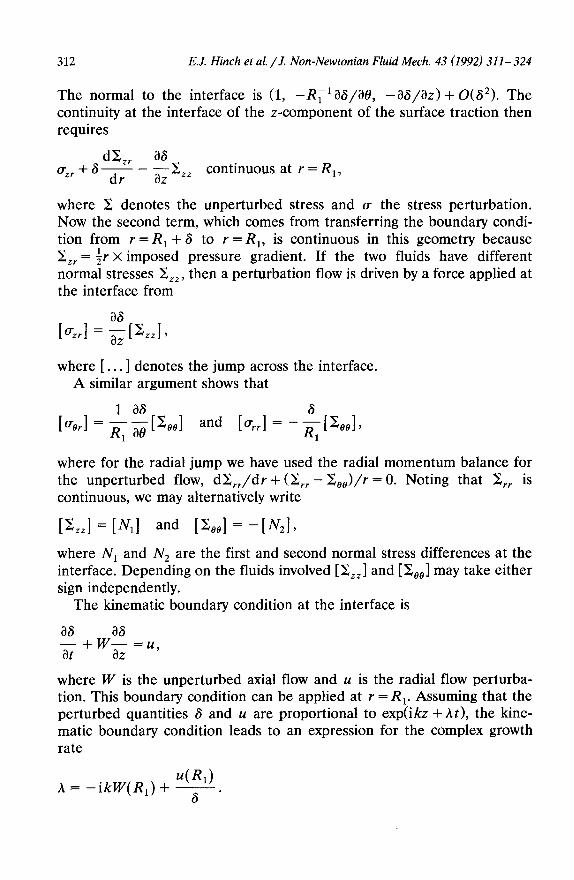
The normal to the interface is (1, -R~‘&3/%3, -X3/b> + O(S2). The continuity at the interface of the z-component of the surface traction then requires
dL i&+8- - Ex
dr az ** continuous at r = R,,
where 2 denotes the unperturbed stress and (T the stress perturbation. Now the second term, which comes from transferring the boundary condi- tion from r = R, + S to r = R,, is continuous in this geometry because ZZV = ir X imposed pressure gradient. If the two fluids have different normal stresses ZZ,, then a perturbation flow is driven by a force applied at the interface from
where [ . . . ] denotes the jump across the interface. A similar argument shows that
where for the radial jump we have used the radial momentum balance for the unperturbed flow, dI;,,/dr + (Z;,, - C,,>/r = 0. Noting that C,, is continuous, we may alternatively write
[%,] = [&I and [&I = +%I~ where N1 and N. are the first and second normal stress differences at the interface. Depending on the fluids involved [C,,] and [&,] may take either sign independently.
The kinematic boundary condition at the interface is
a8 as -$+waz=u,
where W is the unperturbed axial flow and u is the radial flow perturba- tion. This boundary condition can be applied at r = R,. Assuming that the perturbed quantities 6 and u are proportional to exp(ikz + At), the kine- matic boundary condition leads to an expression for the complex growth rate
u(R1) A = -ikW(R,) + 6.
E.J. Hinch et al. /J. Non-Newtonian Fluid mech. 43 (1992) 311- 324 313
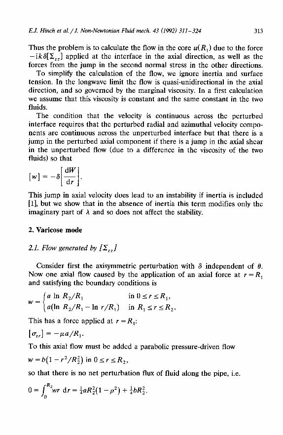
Thus the problem is to calculate the flow in the core u(R,) due to the force - ik8[C,,] applied at the interface in the axial direction, as well as the forces from the jump in the second normal stress in the other directions.
To simplify the calculation of the flow, we ignore inertia and surface tension. In the longwave limit the flow is quasi-unidirectional in the axial direction, and so governed by the marginal viscosity. In a first calculation we assume that this viscosity is constant and the same constant in the two fluids.
The condition that the velocity is continuous across the perturbed interface requires that the perturbed radial and azimuthal velocity compo- nents are continuous across the unperturbed interface but that there is a jump in the perturbed axial component if there is a jump in the axial shear in the unperturbed flow (due to a difference in the viscosity of the two fluids) so that
[w]=-6 g . I 1 This jump in axial velocity does lead to an instability if inertia is included [l], but we show that in the absence of inertia this term modifies only the imaginary part of A and so does not affect the stability.
2. Varicose mode
2.1. Flow generated by [2,,]
Consider first the axisymmetric perturbation with 6 independent of 8. Now one axial flow caused by the application of an axial force at r = R, and satisfying the boundary conditions is
i
a In RJR, inO<r<R,, w=
a(ln R,/R, - In r/R,) in R, 5 r I R,.
This has a force applied at r = R,:
[G] = -w/R,. To this axial flow must be added a parabolic pressure-driven flow
w = b(1 - r2/Rz) in 0 I r I R,,
so that there is no net perturbation flux of fluid along the pipe, i.e.
O=/ “wr dr = iaR$( 1 - p”) + $bRz. 0

314 E.J. Hinch et al. /J. Non-Newtonian Fluid Mech. 43 (1992) 311-324
The net flux of fluid in the core 27rQ(z) can then be calculated
Q(Z) = /,“‘- dr
= - $I?~ In p + +bRf(l - +pz)
ikGR:[ Zz,] =-
4P (-21n p-2+3p2-p4).
Finally by mass conservation
27rR,u(R,) = - &27rQ(z) = -2rikQ,
so the complex growth rate of the instability is
h = -ikW(R,) - ““~~‘;’ (-21n p-2+3p2-p4),
which agrees with Chen’s result [2] for n(a, m2) in his (3.17) in the case of equal viscosities; his m2 = 1. The bracketed final factor in the above expression is positive only when p = RJR, < 0.562. Thus if the core is more elastic, [C,,] < 0, there is an instability when the core occupies less than (0~562)~ = 0.316 of the cross-sectional area.
2.1.1 The mechanism The origin of the instability is the jump across the interface in the
normal stress Zz, of the unperturbed flow. The continuity of the surface traction permits such a jump in the stress tensor at the unperturbed surface. Consider the case of a more elastic core, [IZ:,,] < 0. When the
T = RI + 6(z,t) n
/’ Force -d,[~,,l d
Fig. 1. The imbalance of the unperturbed normal stresses exerts a force - S,[S,,] on the perturbed interface.

E.J. Hinch et al. /J. Non-Newtonian Fluid mech. 43 (1992) 311-324 315
(a) R2
RI--
?-=0
W R2
Fig. 2. The interface is pulled along by the applied force - 6,[8,,], but with no net flow along the pipe. The continuous curve gives the total perturbation velocity profile, combining the simple a-flow having a jump in the viscous stress [cr,J denoted by the curve with the larger dashes, and the parabolic return b-flow denoted by the curve with the smaller dashes. Note that the direction of the net core flow depends on whether the core is small or large.
interface is perturbed, as in Fig. 1 with the interface inclined upwards with 6, > 0, the imbalance in the unperturbed normal stresses exerts a force on the interface -S,[I;,,] in the z-direction. This force drives a perturbation flow with a balancing jump in viscous stresses, [a,,] < 0. The interface will obviously move in the direction of the applied force - a,[ X:,, 1. In order to conserve mass, however, there must be a return (or back) flow which tends to dominate the larger of the core and annulus. Thus in Fig. 2(a) with the small core, the return flow is mainly in the larger annulus and so the net flow in the core is in the direction of the applied force. On the other hand in the case of the large core in Fig. 2(b), the return flow is now mainly in the core and so the net flow in the core is unexpectedly in the opposite direction to the applied force, Figure 3 shows a complete wavelength of the
316 E.J. Hinch et al/J. Non-Newtonian Fluid Mech. 43 (1992) 311-324
RZ
t- flow +
-- --- Rl+d __ -e force ‘A- _
r=o
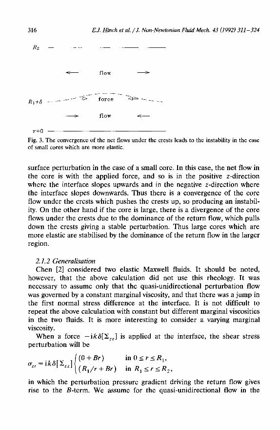
Fig. 3. The convergence of the net flows under the crests leads to the instability in the case of small cores which are more elastic.
surface perturbation in the case of a small core. In this case, the net flow in the core is with the applied force, and so is in the positive z-direction where the interface slopes upwards and in the negative z-direction where the interface slopes downwards. Thus there is a convergence of the core flow under the crests which pushes the crests up, so producing an instabil- ity. On the other hand if the core is large, there is a divergence of the core flows under the crests due to the dominance of the return flow, which pulls down the crests giving a stable perturbation. Thus large cores which are more elastic are stabilised by the dominance of the return flow in the larger region.
2.1.2 Generalisation Chen [2] considered two elastic Maxwell fluids. It should be noted,
however, that the above calculation did not use this rheology. It was necessary to assume only that the quasi-unidirectional perturbation flow was governed by a constant marginal viscosity, and that there was a jump in the first normal stress difference at the interface. It is not difficult to repeat the above calculation with constant but different marginal viscosities in the two fluids. It is more interesting to consider a varying marginal viscosity.
When a force - ik6[Z,,,] is applied at the interface, the shear stress perturbation will be
i
(0 + Br) inOIr<R,, CT ZT = ik6[z:,z] (R,& +Br) in R, srsRz,
in which the perturbation pressure gradient driving the return flow gives rise to the B-term. We assume for the quasi-unidirectional flow in the

E.J. Hinch et al. /J, Non-Newtonian Fluid mech. 43 (1992) 311-324
longwave limit that the perturbation shear stress is accommodated perturbation in the shear rate
aw a,, -- dr - /J(T)
317
by a
where p is the marginal (or differential) viscosity, which for a non-linear fluid will depend on the rheology and the local unperturbed shear rate. The constant B is determined by the condition of no net perturbation flow along the pipe
0 = lR2wr dr 0
/
R2 aw =- -$r* dr
0 ar
The net core flow can now be evaluated
Q(Z) = kR’wr dr
R, aw =w(R,)~Rf- /, ;$r* dr
Thus to determine the long-wave length stability of a co-extrusion flow one must first find the unperturbed flow, then calculate the radial variation of the marginal viscosity, and finally evaluate five integrals of this viscosity.
This procedure has been followed for the shear-thinning rheology
k, = CLOY dW
(I+ Y2/Yo2) ,,,,with Y = zp
which has a marginal viscosity
1+ (1 - n)Y*/Y; P=PO
(1 + y2/y;)1+n’2 *
The radial dependence of the unperturbed shear rate y(r) is determined from C,, = ir x the imposed pressure gradient. Evaluating the integrals of the marginal viscosity for various RJR,, one can determine how the
318 E.J. Hinch et al. /J. Non-Newtonian Fluid Mech. 43 (1992) 311- 324
0.45’ ’ ’ j ’ 0 1 2 3 4
ARd/m
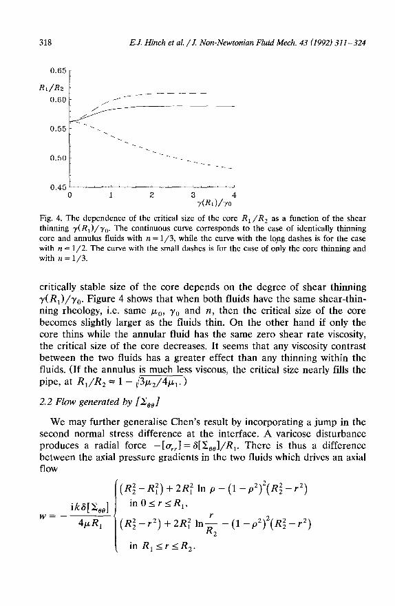
Fig. 4. The dependence of the critical size of the core RI/R, as a function of the shear thinning y(R,)/ yo. The continuous curve corresponds to the case of identically thinning core and annulus fluids with n = l/3, while the curve with the lqng dashes is for the case with n = l/2. The curve with the small dashes is for the case of only the core thinning and with n = l/3.
critically stable size of the core depends on the degree of shear thinning y(R,)/y,. Figure 4 shows that when both fluids have the same shear-thin- ning rheology, i.e. same ,uu,, y0 and 12, then the critical size of the core becomes slightly larger as the fluids thin. On the other hand if only the core thins while the annular fluid has the same zero shear rate viscosity, the critical size of the core decreases. It seems that any viscosity contrast between the two fluids has a greater effect than any thinning within the fluids. (If the annulus is much less viscous, the critical size nearly fills the
pipe, at R,/R, =1-/3qGJ
2.2 Flow generated by [Zee/
We may further generalise Chen’s result by incorporating a jump in the second normal stress difference at the interface. A varicose disturbance produces a radial force -[a,,,.] = 6[&,,]/R,. There is thus a difference between the axial pressure gradients in the two fluids which drives an axial flow
‘(RZ-R~)+~R~III~--(~-~~)~(R$-~~)
i~wml inO<rsR,,
w=- 4pR, ’ (R$-r2) + 2Rf ink - (1 -P~)~(R$ - r”) 2
, in R,srsR,.

E.J. Hinch et al./ J. Non-Newtonian Fluid mech. 43 (1992) 311-324 319
The last term in each expression has been chosen to ensure that there is no net flow along the pipe. Evaluating the net flux of fluid in the core 2+(z)
Q=- ik@[ C,,]
16~ (4ln p+3-4p2+p4),
we find an additional contribution to the complex growth rate A
+ k2R&J 16~
(-41n p-3+4p2-p4).
As the bracketed final factor is positive for all values of p, we have an unstable contribution if the annulus is more elastic in the sense that its negative second normal stress has a larger magnitude than that of the core, [C,,] = - [ N2] > 0. The mechanism of this instability is that where the interface moves into the annulus it removes material with a higher hoop tension (for [X0,] > 0) which leaves a residual positive radial force. This radial force is balanced by a higher pressure in the annulus, which drives the fluid in the annulus away from the crests.
Since for most fluids the second normal stress difference is small compared with the first, the above additional contribution to the complex growth rate will normally make a small correction to the earlier 32% criterion for stability.
2.3 Flow generated by [dW/dr].
If the viscosities of the two fluids differ, then there will be a jump in the unperturbed axial shear, which requires a jump in the perturbation axial velocity evaluated on the unperturbed interface, [w] = -G[dW/dr]. The induced axial flow is
l-2p2(1-r2/R;) inOIr<R,,
o - 2p2(I -r/#) in R, <rsR,.
The last term in each expression has been chosen to ensure no net flow along the pipe. Evaluating the net flux of fluid in the core 27@(z)
Q = $Rf ; (1 - p2)2, [ 1
we find an additional contribution to the complex growth rate A:
-iikR, g (1 -P~)~. i 1

320 E.J. Hinch et al. /J. Non-Newtonian Fluid Mech. 43 (1992) 311-324
This contribution is purely imaginary, corresponding to an adjustment of the W(R,) phase velocity of the disturbance.
3. Sinuous mode
Using the insight gained in the section above, we now explore the possibility of a long-wave sinuous instability having a larger growth rate than the varicose mode which was restrained by the back (or return) flow which will not act on the sinuous mode. We restrict attention to the simplest case in which the perturbation is governed by the same constant viscosity in the two fluids. By linearity we may again superpose the perturbation flows generated by [XZ,l, [&I and [dW/dr]. As the last term will generate a purely imaginary contribution to the complex growth rate (by the reversibility of the inertialess dynamics), we will not calculate it for the sinuous mode.
3.1 Flow generated by [Z,,]
For a sinuous mode, the surface perturbation 6, velocity perturbation (u, u, w) and pressure perturbation p are all proportional to exp(ikx + i0 + At).
In the long-wave limit there is no need for a pressure-driven axial return flow as there was for the varicose mode because the exp i6 dependence guarantees that there is no net flow in both the annulus and the core. Hence the axial flow is simply
-ik8[ C,,] (l-f+ inOIrlR,,
W= 2E.L in R, srsRZ.
In the varicose mode the flow in the cross-section was determined entirely by mass conservation. The problem for the weak flow in the r-0 cross-section is more complicated for the sinuous mode, because the flow has the choice of the radial and azimuthal directions. That selection is made by the momentum equation in the cross-section. Thus we need to solve
V, *u, = -ikw,
o= -vlp+#uv~u.,
where the subscript I means restricted to the two-dimensional r-8 plane. First consider the part of the flow driven directly by the ‘volume source’
term -ikw, i.e. the potential flow
uL=V,$withp/p=Vt4=-ikw.

E.J. Hinch ei al. i J. Non-Newtonian Fluid mech. 43 (1992) 311-324 321
Taking the solution which has @/ar = 0 on r = R, and with 4 continuous there, we find
‘(1 -p2)($r3 - iR:r) inOIr<R,,
(#)=- k2G**l - ip2r3 + $Rfr lnf
2P 4 1
- ;R;(l - p2)r + +R$ \ 1 in R, <rsR,.
This potential flow does not satisfy the boundary conditions on r = R,, but instead has there
k2R?Wzl u=
2P [+ln P + $(l -p2)],
ik2Rf6[ C,,] v=
2P [$ln p + ;(l -p2)].
In order to satisfy the no slip boundary condition at r = R, we need to add to the above potential flow a combination of two solutions of the unforced Stokes equations with a exp i6 dependence. Now one solution is the uniform flow (u, v> = (1, i) while the other is a pressure-driven quadratic flow (u, v> = (r2, 3ir2) (corresponding to (-2xy, 3x2 +y2) in Cartesian co-ordinates). Thus we find the radial flow on the interface
k2R@[%zl u= -
2P ([;1, p + $(l -p2)] +P’[$(l -P2)1)7
and hence the complex growth rate
A = -ikW(R,) + k2RDz*1
16cl. (-4lnp-1+P4).
Now the bracketed final factor is positive for all values of the ratio
P = RJR 2, and hence this sinuous mode is always unstable when the annulus is more elastic than the core. We show for this case the growth rates of the sinuous and varicose modes in Fig. 5-the sinuous mode is always more unstable.
3.1.1 The mechanism The mechanism for this sinuous instability for a more elastic annulus is
indicated in Fig. 6. At a point where 6 is increasing in z, a perturbation

322 E.J. Hinch et al. /J. Non-Newtonian Fluid Mech. 43 (1992) 311- 324
-- / \
/ \
/ \
/ \ \
-0.02 0.0 0.5 1.0
P
Fig. 5. The growth rates Re(A)/k2R~[X,,]p m1 as a function of p = R, /R,. The continuous curve is for the varicose mode, while the dashed curve is for the sinuous mode.
axial flow is generated in the negative z-direction in the upper half of the pipe in both the annulus and the core and in the positive z-direction in the bottom half of the pipe. The opposite occurs where 6 is decreasing. While the flow in the cross-section is complicated, it is seen in the figure that the crests of the wave will rise and the troughs descend, thus amplifying the amplitude of the perturbation to the interface.
This effect is plainly inhibited by the curvature of the streamlines which have an axial elastic stress. The curvature is, however, 0(k2), so producing pressure gradients O( k3) and so modifications to our radial flow 0(k4> which are negligible in the long-wave limit.
Fig. 6. The perturbation axial velocity profile generated in the sinuous mode when the annulus is more elastic. The loss of fluid from above the crests causes them to rise further.
E.J. Hinch et al. /J. Non-Newtonian Fluid mech. 43 (1992) 311-324 323
3.2 Flow generated by [iYZee/
The Stokes flow induced in the cross-section can be obtained in this case by solving the biharmonic equation for the streamfunction $(r, 0) with conditions at the interface
Now the solutions of the biharmonic equation proportional to exp i0 have radial dependencies r3, r In r, r and r-l. Only the first two have an associated pressure field, proportional to 8pr and -2pr-1 respectively. Hence we find
iS[Z&,,] -(l-p4)r3+2R:(1-p2)r inO<rsR,, $=- gpR2
1 i p4( r3 - 2R:r + Rz/r) in R, sr<R,.
This has a radial flow on the interface
which produces a contribution to the complex growth rate A:
As in the varicose mode, we have an unstable contribution if the annulus is more elastic in the sense [&,,I = -[N,] > 0. The mechanism of this insta- bility is very similar to the varicose mode in that where the interface moves up into the annulus it removes material with a higher hoop tension (for [C,,] > 0) which leaves a residual positive radial force. This radial force is balanced by a higher pressure in the annulus, which drives the fluid in the annulus away from the crests, travelling now in the cross-section rather than along the pipe as in the varicose mode. For the sinuous mode there is also a force in the tangential direction which has a smaller effect.
We note that our result for the contribution to the growth rate from [&,I for the sinuous mode is independent of the wavenumber k, so long as kR, -=K 1. Thus although the second normal stress difference is usually small, it may drive a stronger instability than the first normal stress difference in the longwave limit.
Our calculation here is similar to that of Tadmor and Bird [3] who investigated the stability of a ‘wire-coating’ device for which the core is rigid. In that case they found stability for all sizes of core when [C,,] > 0.

324 E.J. Hinch et al. /.I. Non-Newtonian Fluid Mech. 43 (1992) 311-324
Acknowledgement
This work was completed while E.J.H. was a guest at P.M.M.H., E.S.P.C.I., Paris.
References
1 C.S. Yih, Instability due to viscosity stratification, J. Fluid Mech., 27 (1967) 337-352. 2 K.P. Chen, Interfacial instability due to elastic stratification in concentric coextrusion of
two viscoelastic fluids, J. Non-Newtonian Fluid Mech., 40 (1991) 155-175. 3 Z. Tadmor and R.B. Bird, Polym. Eng. Sci. 14 (1974) 124-136.


![Mode coupling instability in friction-induced vibrations a…...Because flutter instability is a mode-coupling phenomenon, a simple self-excited mechanism proposed by Hulten [24-25]](https://img.dokumen.tips/doc/110x75/60044d101b3d0a431a2566ff/mode-coupling-instability-in-friction-induced-vibrations-a-because-flutter-instability.jpg)