Embed Size (px)
Citation preview

BULETINUL INSTITUTULUI POLITEHNIC DIN IAŞI Publicat de
Universitatea Tehnică „Gheorghe Asachi” din Iaşi Volumul 65 (69), Numărul 2, 2019
Secţia CONSTRUCŢII. ARHITECTURĂ
THE INFLUENCES OF THE DURABILITY FACTORS OVER A SPECIAL REINFORCED CONCRETE STRUCTURE'S IN-TIME
BEHAVIOUR
BY
ALEXANDRU FILIP1,* and DANIEL COVATARIU2
Technical University “Gh. Asachi” of Iasi, Faculty of Civil Engineering and Building Services,
1Doctoral School of the Faculty of Civil Engineering and Building Services, 2Department of Civil and Industrial Engineering
Received: May 17, 2019 Accepted for publication: June 20, 2019
Abstract. In the case of reinforced concrete structures, the complex nature
of the effects of the aggressive environment on concrete structures, as well as ensuring a long service life, also requires additional measures to maintain and prevent degradation/deterioration risks. These degradations/deteriorations are based on durability reasons. In this paper, an experimental program for assessing physical and mechanical characteristics (visual inspection of the structure, non-destructive and destructive testing methods) have been presented in the case of a reinforced concrete structure. On the basis of the investigations carried out and the numerical results obtained, the level of degradation/deterioration was estimated and some technical interventions were proposed at the level of the structural elements.
Keywords: water tank; level of degradation; durability; experimental program; rehabilitation solutions.
*Corresponding author: e-mail: [email protected]
66 Alexandru Filip and Daniel Covatariu
1. Introduction
1.1. The Opportunity of In-Time Monitoring of Special Structures Throughout the exploitation of a building, sustainability issues must be
considered taking into account the way in which the structure is being exploited, the maintenance works, and the monitoring of the construction behaviour over time (C244-1993).
The monitoring of the time behaviour of the constructions takes place throughout the life of the construction starting with its execution and it is a systematic activity of collecting and capitalizing the information resulted from observation and measurements on some phenomena and sizes that characterize the properties of the constructions in the process of interaction with the environment (P130-1999).
The monitoring of the construction behaviour can be divided as follows: – current monitoring; – extensive monitoring; – special monitoring. Current monitoring is a behaviour tracking activity that consists of
observing and recording phenomena and parameters that can highlight changes in the construction's ability to meet the resistance, stability and sustainability requirements established by the projects.
This type of monitoring is mandatory and applies to all constructions regardless of type, category or class of importance, and it presents a permanent character.
In the case of special hydro-technical constructions (water tanks) located in aggressive environments, the objectives of the current monitoring are represented by:
– establishing and locating potential sources of aggressive agents, areas where they occur most frequently and at the highest concentration;
– identification and examination of areas subject to aggressive agents or actions during the period of construction exploitation;
– determination of the parameters characterizing the aggressive environment;
– detection and signalling of defects and degradation of the materials used in the construction of structural and non-structural elements (GM 017-2003).
Extensive monitoring of a building has the objective of thoroughly examining all elements and joints of the structure, especially areas where repairs or consolidations have occurred. This type of investigation is performed at well-

Bul. Inst. Polit. Iaşi, Vol. 65 (69), Nr. 2, 2019 67
defined intervals depending on the types and effects of the damage (C244-1993).
For water tanks, extended monitoring can be applied in the following situations:
– in the case when significant deterioration has been identified in the current monitoring stage.
– in the case of exceptional events (floods, earthquakes, landslides, etc.) Special monitoring is a behaviour tracking activity that consists of
systematically measuring, recording and analysing parameter values that define the extent to which constructions maintain their resistance, stability and sustainability requirements specified by projects (P130-1999).
In the case of special hydro-technical constructions (water tanks) located in aggressive environments, the objectives of the special monitoring are represented by:
– oversight of potential aggressive environmental sources caused by technological processes/installations in the event of deficiencies;
– assessing the sustainability of elements/areas that are sensitive to the action of an aggressive environment;
– monitoring some parameters/characteristics of the structural elements in case of damage;
– assessing the influence of the technological process and the impact on the environment.
1.2. Factors Affecting Durability of Concrete Water Tanks
A structure has to meet the operational, resistance and stability
requirements throughout the project lifetime without any significant loss of functionality or unforeseeable maintenance work (SR: EN 1992-1-1:2004).
In the current context, besides the requirements of strength, stability and safety in use, the requirement of durability should be treated with particular attention to reinforced concrete structures due to particular operating conditions (Li et al., 2015).
A proper interpretation of the effects generated by factors affecting durability characteristics could be assessed in a multicriterial analysis in different stages (Fig. 1).
The assessment of durability characteristics should at some point indicate the level of degradation/deterioration of materials/concrete structural elements.
Estimating the level of degradation/deterioration of structural elements of reinforced concrete in water tanks is essential because these types of structures represent strategic objectives within a community.

68 Alexandru Filip and Daniel Covatariu
Fig. 1 − Factors affecting durability in different stages.
In this case, it is necessary to correctly assess the durability of the
materials used in order to establish concrete solutions for eliminating the risk in operation.
2. Experimental Program
2.1. Description of the Analysed Structure
The analysed construction is a ground water tank (Fig. 2) made of reinforced concrete having a capacity of 5,000 m3. It was built in the 1980s and it is still in exploitation, providing the necessary water for the Miroslava village and the Nicolina neighbourhood in Iaşi, Iaşi county.
The water tank has a circular shape in the horizontal plane (Fig. 3) with an inner radius of 13.85 m and a useful height of the tank of 8.05 m. Inside, there is a central reinforced concrete column with the dimensions of 70 70 cm supported by a continuous foundation (C18/22.5), provided at the top with a circular cap.
The wall of the tank is made of prefabricated elements (C25/30) of 17 cm thick. At the top of the wall was made a reinforced concrete belt with the dimensions of 28 20 cm.
At the top, the tank was closed with pre-fabricated T-shaped roof elements (C25/30), radially disposed, supporting one end on the top of the wall and the other on the central pillar cap.
During the operation of the structure, there were performed maintenance and repair works on the inside at the level of the circular wall of the tank for diminishing the corrosion process of the reinforcements. On the outside, periodic waterproofing works were performed at the roof level as a result of water infiltrations. Also, the building has also sustained the effects of earthquakes over the service life.

Bul. Inst. Polit. Iaşi, Vol. 65 (69), Nr. 2, 2019 69
Fig. 2 − Water tank – Miroslava village, Iaşi county.
Fig. 3 − Miroslava water tank:
a) longitudinal section; b) transversal section.
70 Alexandru Filip and Daniel Covatariu
2.1.1. Visual Inspection of the Structure
As a result of the visual analysis of the objective, the main degradations
observed are based on exploitation causes. The degradations resulting from exploitation cases have been identified at the level of the roof elements and walls, areas where the reinforcement is discovered and corroded, segregated concrete areas, concrete expulsions.
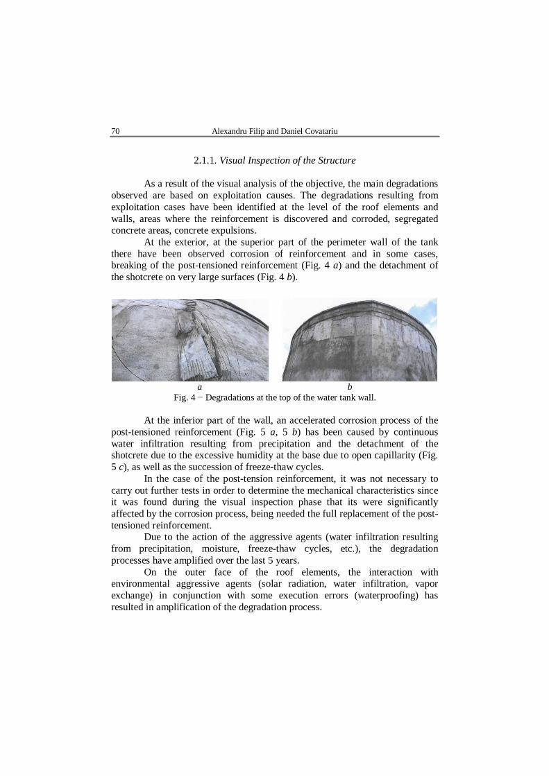
At the exterior, at the superior part of the perimeter wall of the tank there have been observed corrosion of reinforcement and in some cases, breaking of the post-tensioned reinforcement (Fig. 4 a) and the detachment of the shotcrete on very large surfaces (Fig. 4 b).
a b
Fig. 4 − Degradations at the top of the water tank wall.
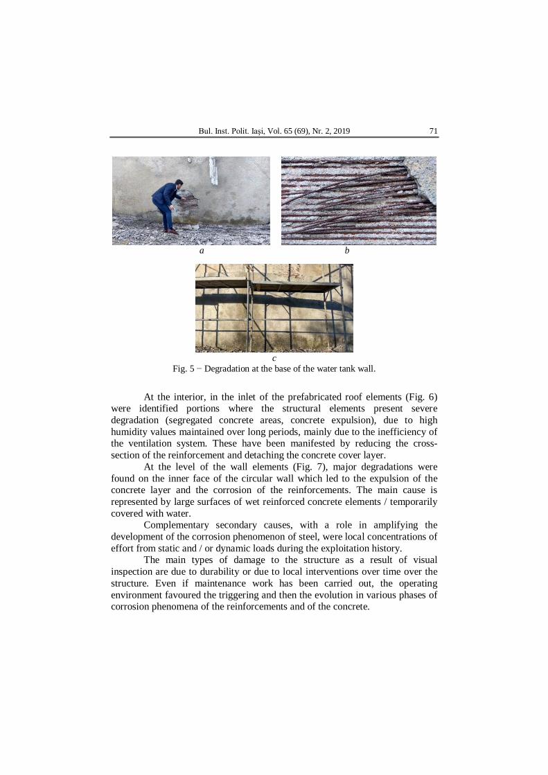
At the inferior part of the wall, an accelerated corrosion process of the post-tensioned reinforcement (Fig. 5 a, 5 b) has been caused by continuous water infiltration resulting from precipitation and the detachment of the shotcrete due to the excessive humidity at the base due to open capillarity (Fig. 5 c), as well as the succession of freeze-thaw cycles.
In the case of the post-tension reinforcement, it was not necessary to carry out further tests in order to determine the mechanical characteristics since it was found during the visual inspection phase that its were significantly affected by the corrosion process, being needed the full replacement of the post-tensioned reinforcement.
Due to the action of the aggressive agents (water infiltration resulting from precipitation, moisture, freeze-thaw cycles, etc.), the degradation processes have amplified over the last 5 years.
On the outer face of the roof elements, the interaction with environmental aggressive agents (solar radiation, water infiltration, vapor exchange) in conjunction with some execution errors (waterproofing) has resulted in amplification of the degradation process.
Bul. Inst. Polit. Iaşi, Vol. 65 (69), Nr. 2, 2019 71
a b
c
Fig. 5 − Degradation at the base of the water tank wall.
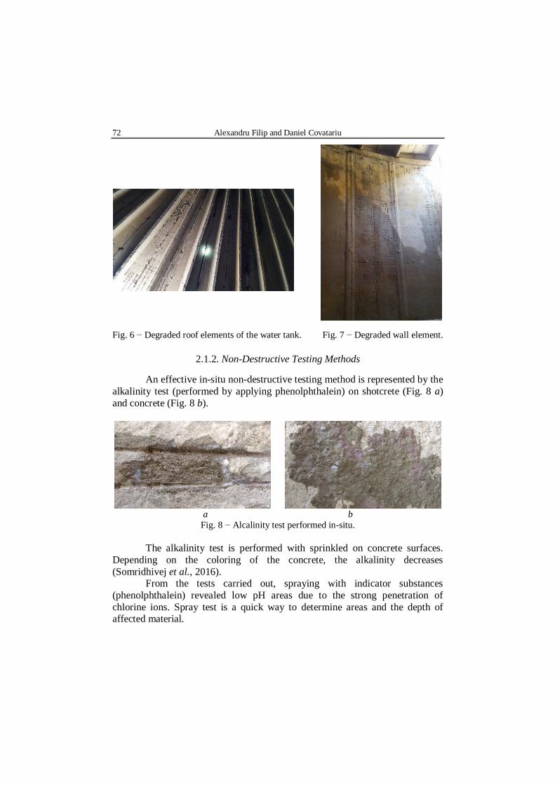
At the interior, in the inlet of the prefabricated roof elements (Fig. 6)
were identified portions where the structural elements present severe degradation (segregated concrete areas, concrete expulsion), due to high humidity values maintained over long periods, mainly due to the inefficiency of the ventilation system. These have been manifested by reducing the cross-section of the reinforcement and detaching the concrete cover layer.
At the level of the wall elements (Fig. 7), major degradations were found on the inner face of the circular wall which led to the expulsion of the concrete layer and the corrosion of the reinforcements. The main cause is represented by large surfaces of wet reinforced concrete elements / temporarily covered with water.
Complementary secondary causes, with a role in amplifying the development of the corrosion phenomenon of steel, were local concentrations of effort from static and / or dynamic loads during the exploitation history.
The main types of damage to the structure as a result of visual inspection are due to durability or due to local interventions over time over the structure. Even if maintenance work has been carried out, the operating environment favoured the triggering and then the evolution in various phases of corrosion phenomena of the reinforcements and of the concrete.
72 Alexandru Filip and Daniel Covatariu
Fig. 6 − Degraded roof elements of the water tank. Fig. 7 − Degraded wall element.
2.1.2. Non-Destructive Testing Methods
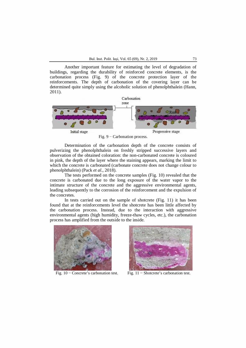
An effective in-situ non-destructive testing method is represented by the
alkalinity test (performed by applying phenolphthalein) on shotcrete (Fig. 8 a) and concrete (Fig. 8 b).
a b
Fig. 8 − Alcalinity test performed in-situ.
The alkalinity test is performed with sprinkled on concrete surfaces. Depending on the coloring of the concrete, the alkalinity decreases (Somridhivej et al., 2016).
From the tests carried out, spraying with indicator substances (phenolphthalein) revealed low pH areas due to the strong penetration of chlorine ions. Spray test is a quick way to determine areas and the depth of affected material.
Bul. Inst. Polit. Iaşi, Vol. 65 (69), Nr. 2, 2019 73
Another important feature for estimating the level of degradation of buildings, regarding the durability of reinforced concrete elements, is the carbonation process (Fig. 9) of the concrete protection layer of the reinforcements. The depth of carbonation of the covering layer can be determined quite simply using the alcoholic solution of phenolphthalein (Hann, 2011).
Fig. 9 − Carbonation process.
Determination of the carbonation depth of the concrete consists of
pulverizing the phenolphthalein on freshly stripped successive layers and observation of the obtained coloration: the non-carbonated concrete is coloured in pink, the depth of the layer where the staining appears, marking the limit to which the concrete is carbonated (carbonate concrete does not change colour to phenolphthalein) (Pack et al., 2018).
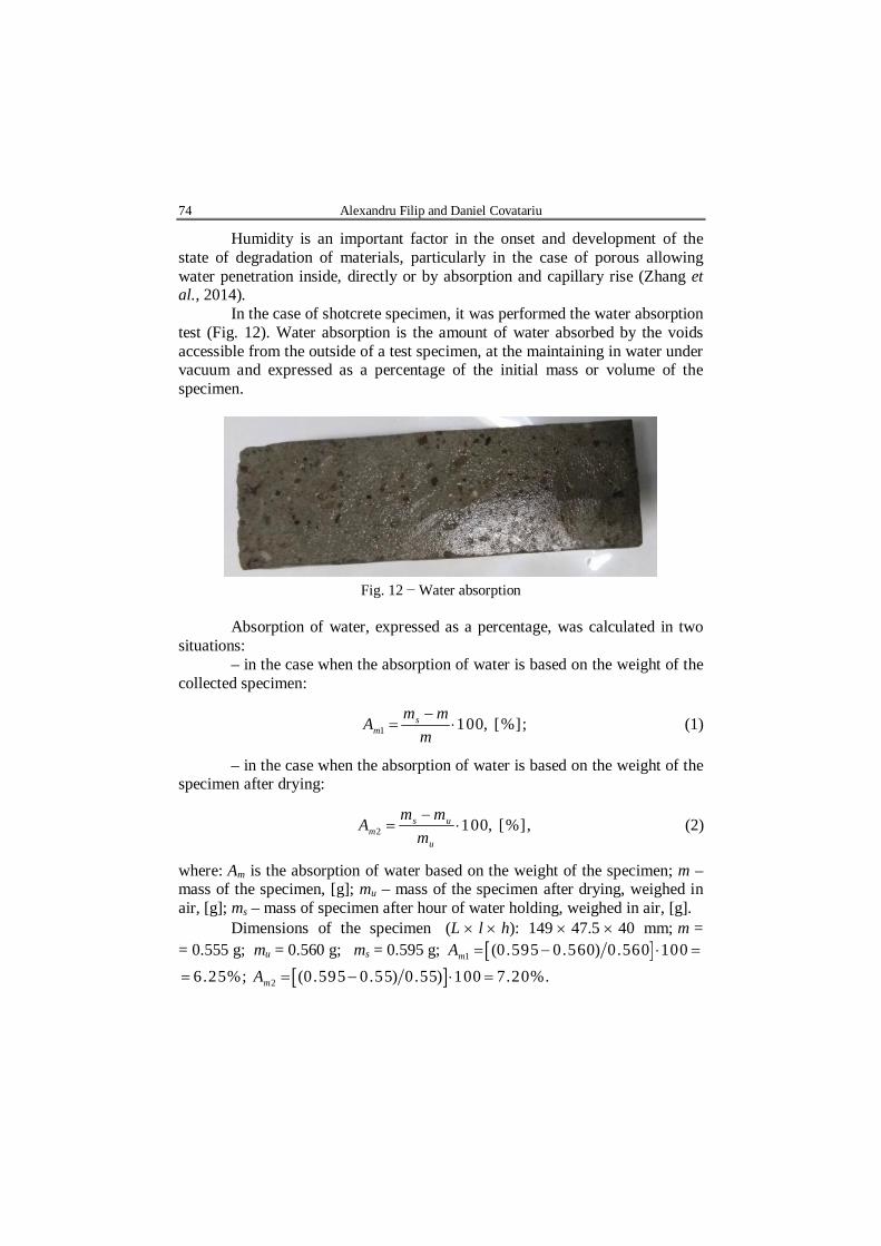
The tests performed on the concrete samples (Fig. 10) revealed that the concrete is carbonated due to the long exposure of the water vapor to the intimate structure of the concrete and the aggressive environmental agents, leading subsequently to the corrosion of the reinforcement and the expulsion of the concretes.
In tests carried out on the sample of shotcrete (Fig. 11) it has been found that at the reinforcements level the shotcrete has been little affected by the carbonation process. Instead, due to the interaction with aggressive environmental agents (high humidity, freeze-thaw cycles, etc.), the carbonation process has amplified from the outside to the inside.
Fig. 10 − Concrete’s carbonation test. Fig. 11 − Shotcrete’s carbonation test.
74 Alexandru Filip and Daniel Covatariu
Humidity is an important factor in the onset and development of the state of degradation of materials, particularly in the case of porous allowing water penetration inside, directly or by absorption and capillary rise (Zhang et al., 2014).
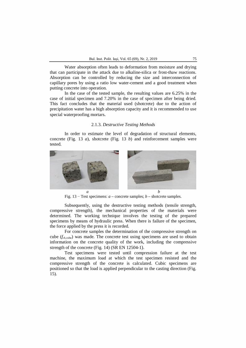
In the case of shotcrete specimen, it was performed the water absorption test (Fig. 12). Water absorption is the amount of water absorbed by the voids accessible from the outside of a test specimen, at the maintaining in water under vacuum and expressed as a percentage of the initial mass or volume of the specimen.
Fig. 12 − Water absorption
Absorption of water, expressed as a percentage, was calculated in two situations:
– in the case when the absorption of water is based on the weight of the collected specimen:
1 100, [%];sm
m mAm
(1)
– in the case when the absorption of water is based on the weight of the specimen after drying:
2 100, [%],s um
u
m mAm
(2)
where: Am is the absorption of water based on the weight of the specimen; m – mass of the specimen, [g]; mu – mass of the specimen after drying, weighed in air, [g]; ms – mass of specimen after hour of water holding, weighed in air, [g].
Dimensions of the specimen (L l h): 149 47.5 40 mm; m = = 0.555 g; mu = 0.560 g; ms = 0.595 g; 1 (0.595 0.560) 0.560 100mA
6.25%; 2 (0.595 0.55) 0.55) 100 7.20%.mA
Bul. Inst. Polit. Iaşi, Vol. 65 (69), Nr. 2, 2019 75
Water absorption often leads to deformation from moisture and drying that can participate in the attack due to alkaline-silica or frost-thaw reactions. Absorption can be controlled by reducing the size and interconnection of capillary pores by using a ratio low water-cement and a good treatment when putting concrete into operation.
In the case of the tested sample, the resulting values are 6.25% in the case of initial specimen and 7.20% in the case of specimen after being dried. This fact concludes that the material used (shotcrete) due to the action of precipitation water has a high absorption capacity and it is recommended to use special waterproofing mortars.
2.1.3. Destructive Testing Methods
In order to estimate the level of degradation of structural elements, concrete (Fig. 13 a), shotcrete (Fig. 13 b) and reinforcement samples were tested.
a b
Fig. 13 − Test specimens: a – concrete samples; b – shotcrete samples.
Subsequently, using the destructive testing methods (tensile strength, compressive strength), the mechanical properties of the materials were determined. The working technique involves the testing of the prepared specimens by means of hydraulic press. When there is failure of the specimen, the force applied by the press it is recorded.
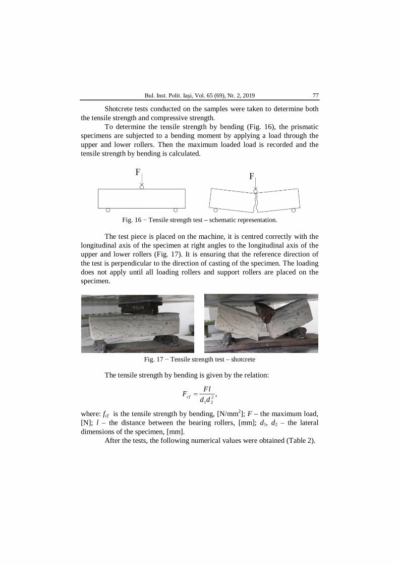
For concrete samples the determination of the compressive strength on cube (fck,cube) was made. The concrete test using specimens are used to obtain information on the concrete quality of the work, including the compressive strength of the concrete (Fig. 14) (SR EN 12504-1).
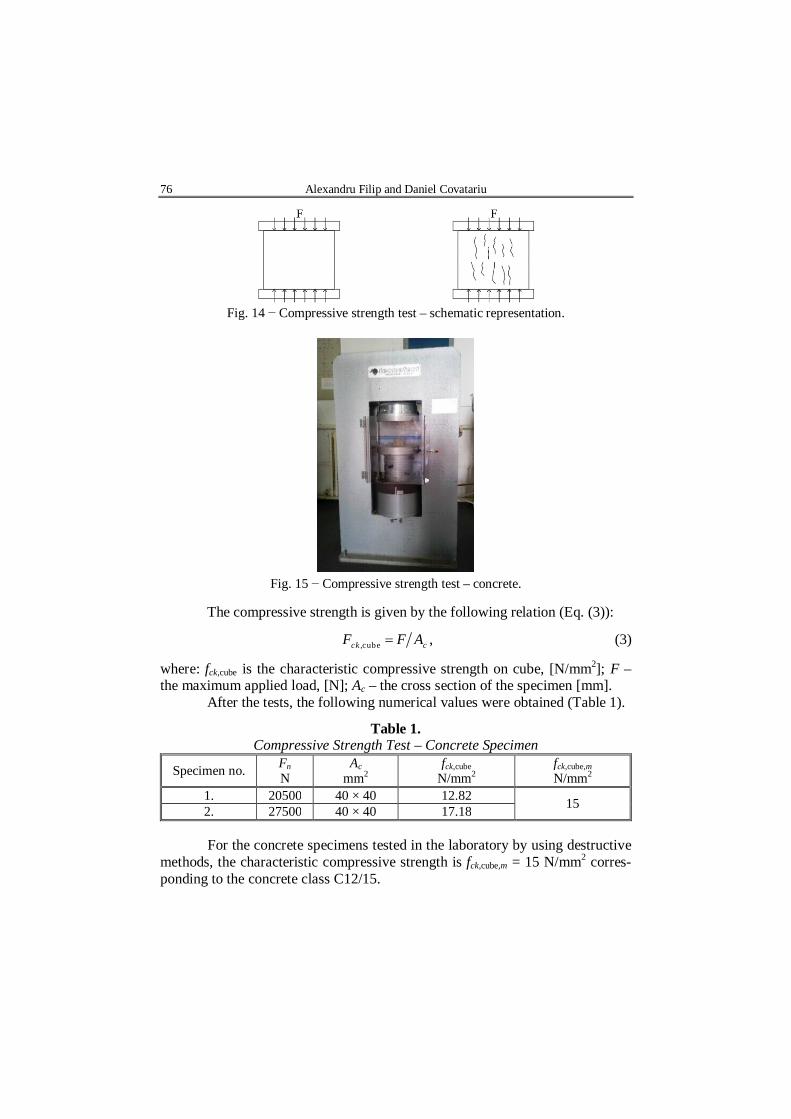
Test specimens were tested until compression failure at the test machine, the maximum load at which the test specimen resisted and the compressive strength of the concrete is calculated. Cubic specimens are positioned so that the load is applied perpendicular to the casting direction (Fig. 15).
76 Alexandru Filip and Daniel Covatariu
Fig. 14 − Compressive strength test – schematic representation.
Fig. 15 − Compressive strength test – concrete.
The compressive strength is given by the following relation (Eq. (3)):
,cube ,ck cF F A (3)
where: fck,cube is the characteristic compressive strength on cube, [N/mm2]; F – the maximum applied load, [N]; Ac – the cross section of the specimen [mm]. After the tests, the following numerical values were obtained (Table 1).
Table 1. Compressive Strength Test – Concrete Specimen
Specimen no. Fn N
Ac mm2
fck,cube N/mm2
fck,cube,m N/mm2
1. 20500 40 × 40 12.82 15 2. 27500 40 × 40 17.18
For the concrete specimens tested in the laboratory by using destructive methods, the characteristic compressive strength is fck,cube,m = 15 N/mm2 corres-ponding to the concrete class C12/15.
Bul. Inst. Polit. Iaşi, Vol. 65 (69), Nr. 2, 2019 77
Shotcrete tests conducted on the samples were taken to determine both the tensile strength and compressive strength.
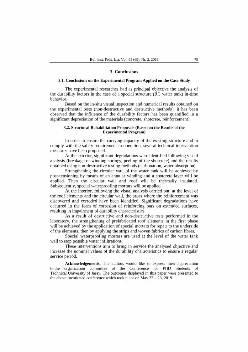
To determine the tensile strength by bending (Fig. 16), the prismatic specimens are subjected to a bending moment by applying a load through the upper and lower rollers. Then the maximum loaded load is recorded and the tensile strength by bending is calculated.
Fig. 16 − Tensile strength test – schematic representation.
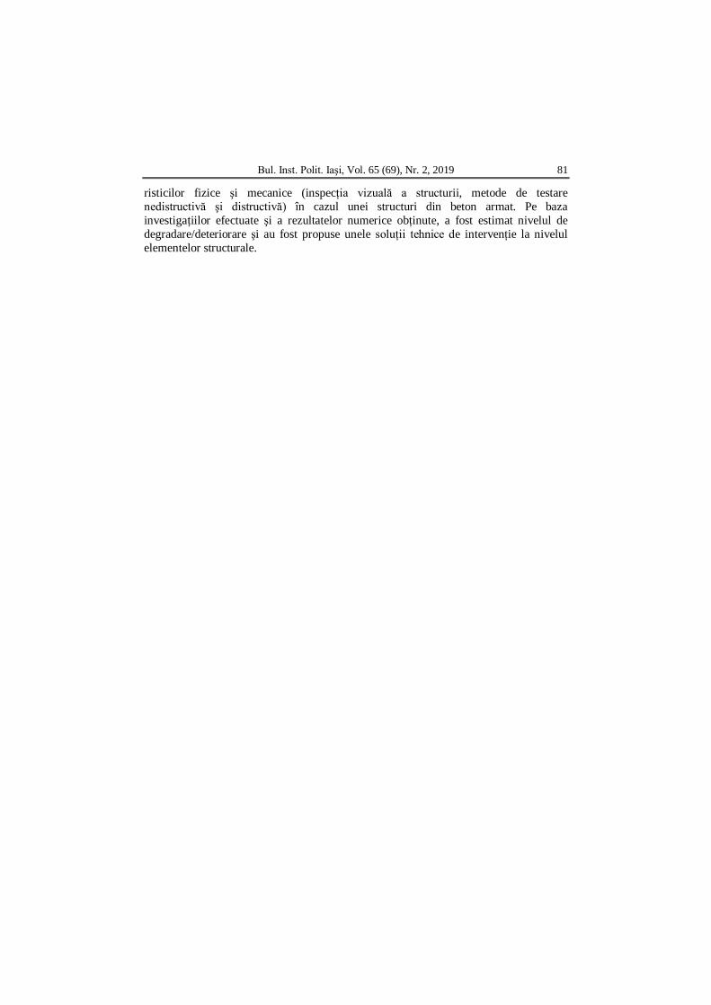
The test piece is placed on the machine, it is centred correctly with the
longitudinal axis of the specimen at right angles to the longitudinal axis of the upper and lower rollers (Fig. 17). It is ensuring that the reference direction of the test is perpendicular to the direction of casting of the specimen. The loading does not apply until all loading rollers and support rollers are placed on the specimen.
Fig. 17 − Tensile strength test – shotcrete
The tensile strength by bending is given by the relation:
21 2
,cfFlF
d d
where: fcf is the tensile strength by bending, [N/mm2]; F – the maximum load, [N]; l – the distance between the bearing rollers, [mm]; d1, d2 – the lateral dimensions of the specimen, [mm].
After the tests, the following numerical values were obtained (Table 2).

78 Alexandru Filip and Daniel Covatariu
Table 2 Tensile Strength Test – Shotcrete Specimen
Specimen no.
Fn N
d1 mm
d2 mm
l mm
fcf N/mm2
fcf,m N/mm2
1 2,500 38 33 114 6.88 6.05 2 1,900 38 33 5.23
For the shotcrete samples tested in the laboratory, using destructive
methods for determining the characteristic value, the tensile strength is fcf,m = = 6.05 N/mm2.
The evaluation of the compressive strength of the shotcrete samples (Fig. 18) was carried out similarly following the steps as in the case of concrete specimen.
Fig. 19 − Compressive strength test – shotcrete After the tests, the following numerical values were obtained (Table 3):
Table 3 Compressive Strength Test – Shotcrete Specimen
Specimen no.
Fn N
Ac mm2
fck,cube N/mm2
fck,cube,m N/mm2
1 29100 40 x 40 18.18
19.50 2 36500 40 x 40 22.82 3 28000 40 x 40 17.50 4 31200 40 x 40 19.50
For the shotcrete specimens tested in the laboratory using destructive methods, the characteristic compressive strength value is fck,cube,m = 19.50 N/mm2.
Bul. Inst. Polit. Iaşi, Vol. 65 (69), Nr. 2, 2019 79
3. Conclusions
3.1. Conclusions on the Experimental Program Applied on the Case Study
The experimental researches had as principal objective the analysis of
the durability factors in the case of a special structure (RC water tank) in-time behavior.
Based on the in-situ visual inspection and numerical results obtained on the experimental tests (non-destructive and destructive methods), it has been observed that the influence of the durability factors has been quantified in a significant depreciation of the materials (concrete, shotcrete, reinforcement).
3.2. Structural Rehabilitation Proposals (Based on the Results of the Experimental Program)
In order to ensure the carrying capacity of the existing structure and to
comply with the safety requirement in operation, several technical intervention measures have been proposed.
At the exterior, significant degradations were identified following visual analysis (breakage of winding springs, peeling of the shotcrete) and the results obtained using non-destructive testing methods (carbonation, water absorption).
Strengthening the circular wall of the water tank will be achieved by post-tensioning by means of an annular winding and a shotcrete layer will be applied. Then the circular wall and roof will be thermally insulated. Subsequently, special waterproofing mortars will be applied.
At the interior, following the visual analysis carried out, at the level of the roof elements and the circular wall, the areas where the reinforcement was discovered and corroded have been identified. Significant degradations have occurred in the form of corrosion of reinforcing bars on extended surfaces, resulting in impairment of durability characteristics.
As a result of destructive and non-destructive tests performed in the laboratory, the strengthening of prefabricated roof elements in the first phase will be achieved by the application of special mortars for repair to the underside of the elements, then by applying the strips and woven fabrics of carbon fibres.
Special waterproofing mortars are used at the level of the water tank wall to stop possible water infiltrations.
These interventions aim to bring in service the analysed objective and increase the nominal values of the durability characteristics to ensure a regular service period.
Acknowledgements. The authors would like to express their appreciation to the organization committee of the Conference for PHD Students of Technical University of Jassy. The outcomes displayed in this paper were presented to the above-mentioned conference which took place on May 22 – 23, 2019.

80 Alexandru Filip and Daniel Covatariu
REFERENCES Covatariu D., Filip A., A Comprehensive Approaching on the Water Tanks Durability’s
Affecting Factors in Different Stages, Bul. Inst. Politehnic, Iaşi, 64(68), 4, 141-156 (2018).
Hann F.E.I., Comportarea in situ a construcţiilor şi aptitudinea lor pentru exploatare – volumul IV. Monitorizarea comportării in situ a construcţiilor, Bucureşti, 2012.
Li Z.J., Tang S.W., Yao Y., Andrade C, Recent Durability Studies On Concrete Structure, Elsevier: Cement and Concrete Research, 78, 143-154, 2015.
Pack S.W., Jung M.S, Kang J.W., Ann K.Y., Kim J., Assessment of Durability of Concrete Structure Subject to Carbonation with Application of Safety Factor, Advances in Materials Science and Engineering, 2018.
Somridhivej B., Boyd E.C, An Assessment of Factors Affecting the Reliability of Total Alkalinity Measurements, Elsevier: Aquaculture, 459, 99-109, 2016.
Zhang S.P., Zong L., Evaluation of Relationship between Water Absorption and Durability of Concrete Materials, Advances in Materials Science and Engineering, 2014.
* * * Ghid pentru inspectare şi diagnosticare privind durabilitatea construcţilor din beton armat şi beton precomprimat, C244-1993, 1993.
* * * Ghid privind urmărirea comportării în exploatare a construcţiilor situate în medii agresive, GM 017-2003, 2003.
* * * Încercare pe beton întărit. Partea 3: Rezistenţa la compresiune a epruvetelor, SR EN 12390-3:2009, 2009.
* * * Încercare pe beton întărit. Partea 5: Rezistenţa la întindere prin încovoiere a epruvetelor, SR:EN 12390:5-2002, 2002.
* * * Normativ pentru urmărirea comportării construcţiilor hidrotehnice, NP 087-2003. * * * Normativ privind comportarea în timp a construcţiilor, P130-1999, 1999. * * * Proiectarea structurilor din beton. Reguli generale şi reguli pentru clădiri, SR:EN
1992-1-1:2004, 2004.
INFLUENŢA FACTORILOR DE DURABILITATE ASUPRA COMPORTĂRII ÎN TIMP A STRUCTURILOR SPECIALE DIN BETON ARMAT
(Rezumat)
În cazul structurilor din beton armat, natura complexă a efectelor mediului
agresiv asupra structurilor din beton, precum şi asigurarea unei durate de exploatare îndelungate, necesită măsuri suplimentare pentru menţinerea şi prevenirea riscurilor de degradare/deteriorare. Aceste degradări/deteriorări se bazează pe motive de durabilitate. În această lucrare, a fost prezentat un program experimental de evaluare a caracte-
Bul. Inst. Polit. Iaşi, Vol. 65 (69), Nr. 2, 2019 81
risticilor fizice şi mecanice (inspecţia vizuală a structurii, metode de testare nedistructivă şi distructivă) în cazul unei structuri din beton armat. Pe baza investigaţiilor efectuate şi a rezultatelor numerice obţinute, a fost estimat nivelul de degradare/deteriorare şi au fost propuse unele soluţii tehnice de intervenţie la nivelul elementelor structurale.