Embed Size (px)
Citation preview
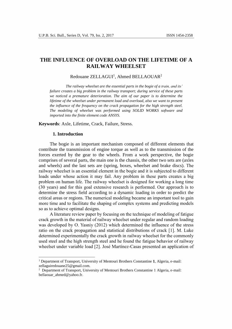
U.P.B. Sci. Bull., Series D, Vol. 79, Iss. 2, 2017 ISSN 1454-2358
THE INFLUENCE OF OVERLOAD ON THE LIFETIME OF A
RAILWAY WHEELSET
Redouane ZELLAGUI1, Ahmed BELLAOUAR2
The railway wheelset are the essential parts in the bogie of a train, and its’
failure creates a big problem in the railway transport; during service of these parts
we noticed a premature deterioration. The aim of our paper is to determine the
lifetime of the wheelset under permanent load and overload, also we want to present
the influence of the frequency on the crack propagation for the high strength steel.
The modeling of wheelset was performed using SOLID WORKS software and
imported into the finite element code ANSYS.
Keywords: Axle, Lifetime, Crack, Failure, Stress.
1. Introduction
The bogie is an important mechanism composed of different elements that
contribute the transmission of engine torque as well as to the transmission of the
forces exerted by the gear to the wheels. From a work perspective, the bogie
comprises of several parts, the main one is the chassis, the other two sets are (axles
and wheels) and the last sets are (spring, boxes, wheelset and brake discs). The
railway wheelset is an essential element in the bogie and it is subjected to different
loads under whose action it may fail. Any problem in these parts creates a big
problem on human life. The railway wheelset is designed for working a long time
(30 years) and for this goal extensive research is performed. Our approach is to
determine the stress field according to a dynamic loading in order to predict the
critical areas or regions. The numerical modeling became an important tool to gain
more time and to facilitate the shaping of complex systems and predicting models
so as to achieve optimal designs. A literature review paper by focusing on the technique of modeling of fatigue
crack growth in the material of railway wheelset under regular and random loading
was developed by O. Yasniy (2012) which determined the influence of the stress
ratio on the crack propagation and statistical distributions of crack [1]. M. Luke
determined experimentally the crack growth in railway wheelset for the commonly
used steel and the high strength steel and he found the fatigue behavior of railway
wheelset under variable load [2]. José Martínez-Casas presented an application of
1 Department of Transport, University of Mentouri Brothers Constantine 1, Algeria, e-mail:
[email protected]. 2 Department of Transport, University of Mentouri Brothers Constantine 1 Algeria, e-mail:

72 Redouane Zellagui, Ahmed Bellaouar
the critical side in different elements of railway bogie (axles, wheels, rail) and the
fracture behavior of the previous elements under harmonic load [3]. K. Hirakawa
performed an analysis of different causes of failure for a railway wheelset and the
fretting fatigue crack in the critical side of the wheelset. He also found how to
improve the wheelset railway manufacture. Figure 2 shows the variable load
applied on the wheelset, [4].
For explaining more of the importance of our study, Figure 1 (left) describes
a big damage which happened in Italy in June 29th, 2009 when a train accident
occurred due to the existence of a small crack in the wheelset (the crack wheelset
is shown in the right picture). As a result of this accident, 32 people died and big
damages occurred in the wagons.
Fig 1: Fracture in wheelset [8].
Fig 2: Typical stress-time history [4].
Crack tip region

The influence of overload on the lifetime of a railway wheelset
2. Fracture mode
The fatigue mechanisms show that, it is not often necessary to consider only
the possibility of an existing crack, but also the crack growth propagation, to ensure
that the cracks do not reach the critical length. It is necessary to have quantitative
data to charactere the fatigue crack growth.
In 1960, Paris et al. have shown the relationship between fatigue crack
growth (da / dN) and the stress intensity factor (K). Because the value of stress
intensity factor changes during variable load, one defines the magnitude of the
stress intensity factor: ΔK = Kmax – Kmin, where Kmax and Kmin are the extreme
values of K during the cycle. In logarithmic scale, the crack growth rate (da / dN)
is shown in the Figure.3. three different zones can be noticed:
✓ Range I is characterized by the crack propagation threshold. The velocity
goes to zero, for a value ΔKth which is called propagation threshold.
✓ Range II, is the Paris law zone. It is characterized by the crack propagation
velocity when ΔK increases. Paris et al. have linked the propagation velocity
and magnitude of the ΔK by the relationship:
nKC
dN
da (1)
where C and n are experimental parameters depending on material and test
conditions (load ratio, environment ...).
✓ Range III corresponds to a very rapid acceleration of the speed of crack. The
stress intensity factor is close to the critical value Kc corresponding to the
final failure.
Fig 3. Fatigue crack extension characteristics (da/dN) based on ΔKeff.

74 Redouane Zellagui, Ahmed Bellaouar
3. The mechanical model
The studied mechanism is shown in Fig. 5. It is very important to present
different parts of the bogie and the relation between this parts. Using this model we
can determine different problems in the bogie and the dangerous area.
Fig 4: Scheme of railway bogie.[9]
Fig 5: Numerical model of the railway bogie.
Chassis
Axle
Wheel Axle
Box
Primary
suspension
Brake Disc
Secondary
suspension Frame Gear
Box

The influence of overload on the lifetime of a railway wheelset
The calculations are done according to the information and conditions given
by the clients, which are the train characteristics listed in Table 1. Table 1
Train characteristic
Value
Body mass 77600Kg
Chassis mass 500Kg
Wheel mass 500Kg
Spring factor of primary suspension 788MN/m
Damping factor of primary suspension 3.5KN-s/m
Spring factor of secondary suspension 6.11MN/m
Damping factor of secondary suspension 158KN-s/m
Maximum load in wheelset. 25 tonnes
Axle mass 370Kg
A detailed view of the studied wheelset is shown in Fig. 6. As seen in this
figure, the solid shaft has been made as one body and its cross-section is circular.
In several locations on the shaft, fillets with different radius are seen which act as
stress concentrators.
Fig.6. Detail of Railway wheelset [9]
In order to analyze the mechanical behavior of the railway wheelset, a general
model using the Ansys software was realized. The applied mechanical properties
are listed in Table 2. According to the previously defined loads, the critical areas of
the wheelset are defined. Table 2
Mechanical properties
Yield
stress
(MPa)
KIC
(MPa*m0.5)
Plane strain
KID
(MPa*m0.5)
Plane stress
C N
350 121 242 3e-12 3.43

76 Redouane Zellagui, Ahmed Bellaouar
The FE model of railway wheelset is shown in Fig. 7. The analysis model of
the axle consists of 110453 nodes and 90265 elements. In this model, the x-axis is
longitudinal, the y-axis is transversal and the z-axis is on the vertical direction
respectively. Several loading cases were considered as to make a comprehensive
study on the mechanical behavior of the wheelset using Ansys.
Fig 7: FE model of railway wheelset.
Generally, the form of the cracks in wheelset is semi elliptical, so for our
geometric model a semi elliptical surface crack depth is chosen with depth a and
width 2c (Figure 8).
Fig.8: The elliptical crack, [7].
The calculation of stress intensity factor is given by relation (2), where
,,,
D
c
D
a
c
aFs
is a function of geometry.
Q
a
D
c
D
a
c
aFK s
,,, (2)
ws fgf
D
aM
D
aMMF
4
3
2
21 (3)
Pma
x
Pma
x

The influence of overload on the lifetime of a railway wheelset
For: 1c
a
c
aM 09.013.11
(4)
c
aM
2.0
89.054.02
(5)
24
3 114
65.0
15.0
c
a
c
aM (6)
22
sin135.01.01
D
ag (7)
4
1
22
2
sincos
c
af (8)
21
2sec
D
a
D
cfw
(9)
4. Results and discussion
In our model of crack, we start from an initial crack length a0 of
approximately 4 mm. Each specimen was cycled at a stress ratio R = -1 and the
nominal stress range of Pmax = 7.5 MPa (pressure applied on the wheelset). Fig. 2
shows the difficulties in applying this type of load to our model. For this point, the
problem has been simplified in two types of loading, in the second step; we have
chosen that after each 10 cycles of constant amplitude one overload of 1.2Pmax. The
overload on the fatigue crack growth behavior of our study is shown in Fig. 9; we
applied one cycle of 1.2Pmax after each 10 cycles of constant amplitude of Pmax.

78 Redouane Zellagui, Ahmed Bellaouar
Fig.9: Overload spectra.
In Fig. 10 (a, b) we present the variation of the crack length with and without
overload. So, we noticed that in figure 10 (a) the crack length is increasing slowly
and from 8.9x10⁹ cycle it starts to increase quickly. In figure 10 (b) the crack length
is increasing slowly up to 8.3x10⁹ cycles, when it begins to increase quickly.
Also, we noticed that in Figure 11(a) the crack growth is increasing slowly
up to a crack length a = 70 mm, then it increases quickly. In Figure 11 (b) it can be
seen that the crack velocity is small up to a = 50mm and then it begins to pertubate.
In this point, we found that there is a big influence of overload on railway wheelset.
Fig.10 (a, b): Variation of crack length. (a) Without overload, (b) With overload
-2,50x10⁹ 0,00 2,50x10
95,00x10
97,50x10
91,00x10
10
-0,025
0,000
0,025
0,050
0,075
0,100
0,125
Cra
ck le
ngth
(m
)
Number of cycles
0,00 2,50x10⁹
5,00x10⁹
7,50x10⁹
1,00x10¹⁰
-0,025
0,000
0,025
0,050
0,075
0,100
0,125
Cra
ck le
ng
th (
m)
Number of cycle
1.2Pmax
Pmax Time(s)
Load
(MPa)
)
10 cycles 1 cycle

The influence of overload on the lifetime of a railway wheelset
-0,025 0,000 0,025 0,050 0,075 0,100 0,125-2,50x10
-9
0,00
2,50x10⁻⁹
5,00x10⁻⁹
7,50x10⁻⁹
1,00x10⁻⁸
1,25x10⁻⁸
1,50x10⁻⁸
da/d
N (
m/c
ycle
)
Crack length (m)
Fig.11 (a,b) :Variation crack growth. (a) Without overload, (b) With overload
Fig. 12 shows the influence of frequency on the life of the wheelset. We can
notice that the relationship between the variation of the frequency and the lifetime
is inversely proportional. The influence of frequency is very important. We found
that when we decrease the frequency, an increase of the lifetime is noticed:
8.8887*109 s in normal load, and 8.23198*109 s in the case when we have an
overload.
0,000 0,025 0,050 0,075 0,100 0,125
0,0
2,0x10⁹
4,0x10⁹
6,0x10⁹
8,0x10⁹
1,0x10¹⁰
Lifetim
e (
s)
Crack length (m)
f=50Hz
f=30Hz
f=20Hz
f=10Hz
f=5Hz
f=1Hz
-0,025 0,000 0,025 0,050 0,075 0,100 0,125
0,0
2,0x10⁹
4,0x10⁹
6,0x10⁹
8,0x10⁹
1,0x10¹⁰
Lifetim
e (
s)
Crack length (m)
f=50Hz
f=30Hz
f=20Hz
f=10Hz
f=5Hz
f=1Hz
Fig. 12 (a,b):Influence of frequency. (a) Without overload, (b) With overload
In the Figure below we suggest the value of frequency is 1 Hz and we found
that the lifetime of wheelset increases when the overload decreases. In the case
f = 1Hz a bigger increase of the lifetime is gained 6.5672*108 s.
Fig. 13: Variation of lifetime.
-0,025 0,000 0,025 0,050 0,075 0,100 0,125-1,0x10
-9
0,0
1,0x10⁻⁹
2,0x10⁻⁹
3,0x10⁻⁹
4,0x10⁻⁹
5,0x10⁻⁹
6,0x10⁻⁹
7,0x10⁻⁹
8,0x10⁻⁹
9,0x10⁻⁹
da/d
N (
m/c
ycle
)
Crack length (m)
-2,50x10⁹ 0,00 2,50x10
95,00x10
97,50x10
91,00x10
10
-0,025
0,000
0,025
0,050
0,075
0,100
0,125
Cra
ck length
(m
)
Number de cycles
Without ouverload
With overload
Lif
etim
e (s
)

80 Redouane Zellagui, Ahmed Bellaouar
5. Conclusion
The paper studies the influence of overload on the crack propagation velocity
and the lifetime of wheelset with and without overload. It is shown that its influence
is very important on the wheelset.
The results we obtained are the following:
✓ In the first case, fatigue life is very high comparing to the second one with
the difference of 6.5672*108 s.
✓ In the other case, we noticed that the frequency influence is very important
especially in the case of a normal load.
Perceptively, we are going to decrease the crack growth by decreasing the
frequency of wheelset by the reinforcement of the bogie damping system by
improving its design.
Acknowledgments
The acknowledgment goes to the Transportation Engineering and
Environment Laboratory (Constantine-Algeria).
Nomenclature
ΔK: stress intensity factor.; Kc: Critical stress intensity factor.;
C: Paris coefficient ; n: Paris exponent ;
KImax: Maximal stress intensity factor.
KImin: Minimal stress intensity factor.; a:Crack length. N: Number on cycle.
R E F E R E N C E S
1) O. Yasniy, Y. Lapusta, Y. Pyndus, A. Sorochak, V. Yasniy, Assessment of lifetime of railway axle,
Ukraine 2011.
2) M. Luke, I. Varfolomeev, K. Lütkepohl, A. Esderts, Fracture mechanics assessment of railway
axles: Experimental characterization and computation, Germany 2009.
3) José Martínez-Casas , Laura Mazzola, Luis Baeza, Stefano Bruni, Numerical estimation of
stresses in railway axles using a train–track interaction model, Spain 2012.
4) K. Hirakawa, K. Toyama, M. Kubota, The analysis and prevention of failure in railway axles,
Japan 1998.
5) S. Beretta, M. Carboni, Variable amplitude fatigue crack growth in a mild steel for railway
axles:Experiments and predictive models, Italy 2010.
6) M. Madia, S. Beretta, M. Schödel, U. Zerbst, M. Luke, I, Varfolomeev Stress intensity factor
solutions for cracks in railway axles, Italy 2010.
7) M. Luke, I. Varfolomeev , K. Lütkepohl, A. Esderts, Fatigue crack growth in railway axles:
Assessment concept and validation tests, Germany 2010.
8) F. Lorenzo, railway accident investigation report, Italy 2013
9) Catalogue of spare parts Algeria SNTF- 2008.