Embed Size (px)
Citation preview

1987
The in situ generation and reactive quench of diazoniumcompounds in the synthesis of azo compounds inmicroreactorsFaith M. Akwi and Paul Watts*
Full Research Paper Open Access
Address:Nelson Mandela Metropolitan University, University Way, PortElizabeth, 6031, South Africa
Email:Paul Watts* - [email protected]
* Corresponding author
Keywords:azo coupling; diazotization; microreactor; scale up
Beilstein J. Org. Chem. 2016, 12, 1987–2004.doi:10.3762/bjoc.12.186
Received: 09 June 2016Accepted: 14 August 2016Published: 06 September 2016
This article is part of the Thematic Series "Automated chemicalsynthesis".
Guest Editor: I. R. Baxendale
© 2016 Akwi and Watts; licensee Beilstein-Institut.License and terms: see end of document.
AbstractIn this paper, a micro-fluidic optimized process for the continuous flow synthesis of azo compounds is presented. The continuous
flow synthesis of Sudan II azo dye was used as a model reaction for the study. At found optimal azo coupling reaction temperature
and pH an investigation of the optimum flow rates of the reactants for the diazotization and azo coupling reactions in Little Things
Factory-MS microreactors was performed. A conversion of 98% was achieved in approximately 2.4 minutes and a small library of
azo compounds was thus generated under these reaction conditions from couplers with aminated or hydroxylated aromatic systems.
The scaled up synthesis of these compounds in PTFE tubing (i.d. 1.5 mm) was also investigated, where good reaction conversions
ranging between 66–91% were attained.
1987
IntroductionGoing green, a familiar catch phrase in the chemical industry, in
addition to environment protection laws have influenced and
also triggered the development of cleaner methods of produc-
tion. The production of azo compounds is one controversial
sector of the fine chemical industry; color is highly desired and
used in almost everything, but the waste generated from the
production of these compounds is detrimental to the environ-
ment and human health.
Following the principles of green chemistry [1,2] such as less
hazardous chemical synthesis, efficient atom economy, reduc-
tion of waste produced, some alternative cleaner methods for
Beilstein J. Org. Chem. 2016, 12, 1987–2004.
1988
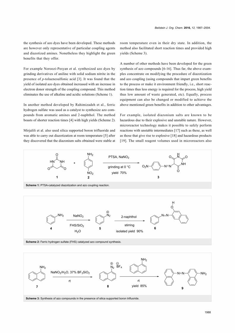
Scheme 1: PTSA-catalyzed diazotization and azo coupling reaction.
Scheme 2: Ferric hydrogen sulfate (FHS) catalyzed azo compound synthesis.
Scheme 3: Synthesis of azo compounds in the presence of silica supported boron trifluoride.
the synthesis of azo dyes have been developed. These methods
are however only representative of particular coupling agents
and diazotized amines. Nonetheless they highlight the green
benefits that they offer.
For example Noroozi-Pesyan et al. synthesized azo dyes by
grinding derivatives of aniline with solid sodium nitrite in the
presence of p-toluenesulfonic acid [3]. It was found that the
yield of isolated azo dyes obtained increased with an increase in
electron donor strength of the coupling compound. This method
eliminates the use of alkaline and acidic solutions (Scheme 1).
In another method developed by Rahimizadeh et al., ferric
hydrogen sulfate was used as a catalyst to synthesize azo com-
pounds from aromatic amines and 2-naphthol. The method
boasts of shorter reaction times [4] with high yields (Scheme 2).
Mirjalili et al. also used silica supported boron trifluoride and
was able to carry out diazotization at room temperature [5] after
they discovered that the diazonium salts obtained were stable at
room temperature even in their dry state. In addition, the
method also facilitated short reaction times and provided high
yields (Scheme 3).
A number of other methods have been developed for the green
synthesis of azo compounds [6-16]. Thus far, the above exam-
ples concentrate on modifying the procedure of diazotization
and azo coupling (using compounds that impart green benefits
to the process or make it environment friendly, i.e., short reac-
tion times thus less energy is required for the process, high yield
thus low amount of waste generated, etc). Equally, process
equipment can also be changed or modified to achieve the
above mentioned green benefits in addition to other advantages.
For example, isolated diazonium salts are known to be
hazardous due to their explosive and unstable nature. However,
microreactor technology makes it possible to safely perform
reactions with unstable intermediates [17] such as these, as well
as those that give rise to explosive [18] and hazardous products
[19]. The small reagent volumes used in microreactors also

Beilstein J. Org. Chem. 2016, 12, 1987–2004.
1989
Scheme 4: Phase transfer catalyzed azo coupling of 5-methylresorcinol in microreactors.
Scheme 5: Synthesis of yellow pigment 12 in a micro-mixer apparatus.
reduce the amount of acidic and alkaline waste associated with
the synthesis of azo compounds during research and develop-
ment.
In the conventional way of performing reactions, the amount of
waste generated is dealt with at the end of the reaction. On the
contrary, microreactor technology enables the reduction of
waste generated by increasing the atom efficiency of reactions
and in so doing, the quantity of starting materials is reduced in
turn minimizing the amount of waste generated. This aspect of
microreactor technology will definitely prove to be quite impor-
tant in the synthesis of these compounds more so that their
production, however important they are, has adverse effects on
the environment, mammals [20,21] and aquatic life. Even with a
number of dye degradation techniques [22] currently being em-
ployed in waste water treatment, a certain percentage of the
dyestuffs is still found in water bodies. This therefore is motiva-
tion for developing better methods or techniques or processes
that can be used independently or in conjunction with the
existing techniques. Microreactor technology is one such tech-
nology that can be used in the manufacture of these dyes. If
used in conjunction with existing azo dye degradation tech-
niques the amount of waste generated can easily be managed.
Hisamoto et al., for example, used ‘phase transfer synthesis’ in
micro-chips for a diazo-coupling reaction [23]. The authors did
not however employ a phase transfer catalyst, but rather the
principle to increase the reaction selectivity in the diazo cou-
pling of 5-methylresorcinol (10) to p-nitrobenzene diazonium
tetrafloroborate (11) in a biphasic laminar flow reaction system.
The bi-phasic reaction media consisted of compound 10 dis-
solved in the organic phase, ethyl acetate (C4H8O2) and 11 in
the aqueous phase (Scheme 4). The large specific interfacial
areas and reduced molecular diffusion distances were found to
have played a role in avoiding the undesirable side reaction,
thus increasing the atom economy in the reaction. This in turn
reduces the amount of waste generated after the reaction.
A reaction conversion of almost 100% was attained in
2.3 seconds. The same reaction performed at a macro scale and
at a strong stirring rate providing a calculated specific interfa-
cial area of 40 cm2, gave a comparable conversion to that
attained at a micro scale (calculated specific interfacial area of
80 cm2).
In the synthesis of azo dyes and pigments, the cost of produc-
tion and quality of the product cannot be over looked. Wille et
al., in their investigative research involving the synthesis of two
azo pigments (yellow and red pigments) in microreactors [24],
demonstrated that scaling out in the microreactors provided
better and more consistent quality of the pigments as compared
to scale up in the batch vessels.
Similarly, yellow pigment 12 (15) was also synthesized by
Pennemann et al. (Scheme 5) using a micro-mixer apparatus
[25]; the group’s comparison of the results with the batch syn-
thesis of the said pigment 15 affirmed the notion that mixing is
an essential unit operation in the synthesis of azo pigments.
The pigment synthesized in a micro-mixer (25 µm channel
width) at a flow rate of 30 mL/min had smaller pigment size
distribution compared to the batch synthesized pigment. The
fast mixing in the micro-mixer was noted to be responsible for
Beilstein J. Org. Chem. 2016, 12, 1987–2004.
1990
Scheme 6: Continuous flow synthesis of Sudan II azo dye in LTF-MS microreactors.
the improvement of glossiness (73%) and tinctorial strength
(66%) of the yellow pigment thus yielding a good quality
product.
With all the various applications of azo compounds previously
mentioned, it is therefore important to develop an optimized
process for their synthesis. This was achieved with the use of
the microreactor technology. Since the benefits of microreactor
technology are well documented in literature [26-30],
the ease of reaction parameter optimization in the synthesis of
azo compounds in microreactors is highlighted.
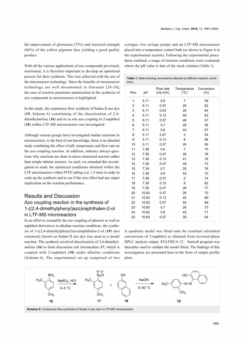
In this study, the continuous flow synthesis of Sudan II azo dye
(19, Scheme 6) constituting of the diazotization of 2,4-
dimethylaniline (16) and its in situ azo coupling to 2-naphthol
(18) within LTF-MS microreactors was investigated.
Although various groups have investigated similar reactions in
microreactors, to the best of our knowledge, there is no detailed
study combining the effect of pH, temperature and flow rate on
the azo coupling reaction. In addition, industry always ques-
tions why reactions are done in micro structured reactors rather
than simple tubular reactors. As such, we extended this investi-
gation to study the optimized conditions obtained within the
LTF microreactors within PTFE tubing (i.d. 1.5 mm) in order to
scale up the synthesis and to see if the size effect had any major
implication on the reaction performance.
Results and DiscussionAzo coupling reaction in the synthesis of1-((2,4-dimethylphenyl)azo)naphthalen-2-olin LTF-MS microreactorsIn an effort to exemplify the azo coupling of phenols as well as
naphthol derivatives in alkaline reaction conditions, the synthe-
sis of 1-((2,4-dimethylphenyl)azo)naphthalen-2-ol (19) also
commonly known as Sudan II azo dye was used as a model
reaction. The synthesis involved diazotization of 2,4-dimethyl-
aniline (16) to form diazonium salt intermediate 17, which is
coupled with 2-naphthol (18) under alkaline conditions
(Scheme 6). The experimental set up comprised of two
syringes, two syringe pumps and an LTF-MS microreactor
placed into a temperature control bath (as shown in Figure 6 in
the experimental section). Following the experimental proce-
dures outlined, a range of reaction conditions were evaluated,
where the pH value is that of the stock solution (Table 1).
Table 1: Data showing conversions attained at different reaction condi-tions.
Run pHFlow rate(mL/min)
Temperature(°C)
Conversion(%)
1 5.11 0.6 7 592 5.11 0.37 26 623 5.11 0.03 25 644 5.11 0.13 40 635 5.11 0.37 46 576 5.11 0.7 26 557 5.11 0.6 43 578 5.11 0.37 2 549 5.11 0.13 8 56
10 5.11 0.37 26 5611 7.39 0.6 7 7012 7.39 0.37 26 7813 7.39 0.13 41 7614 7.39 0.37 49 7315 7.39 0.7 25 7616 7.39 0.6 43 7217 7.39 0.37 2 7418 7.39 0.13 8 8219 7.39 0.37 26 7720 10.83 0.37 26 7221 10.83 0.13 40 6922 10.83 0.37 50 6923 10.83 0.7 26 7324 10.83 0.6 43 7125 10.83 0.37 26 64
A quadratic model was fitted onto the resultant calculated
conversions of 2-naphthol as obtained from reversed-phase
HPLC analysis output. STATISCA 12 – Statsoft program was
thereafter used to validate the model fitted. The findings of this
investigation are presented here in the form of simple profile
plots.
Beilstein J. Org. Chem. 2016, 12, 1987–2004.
1991
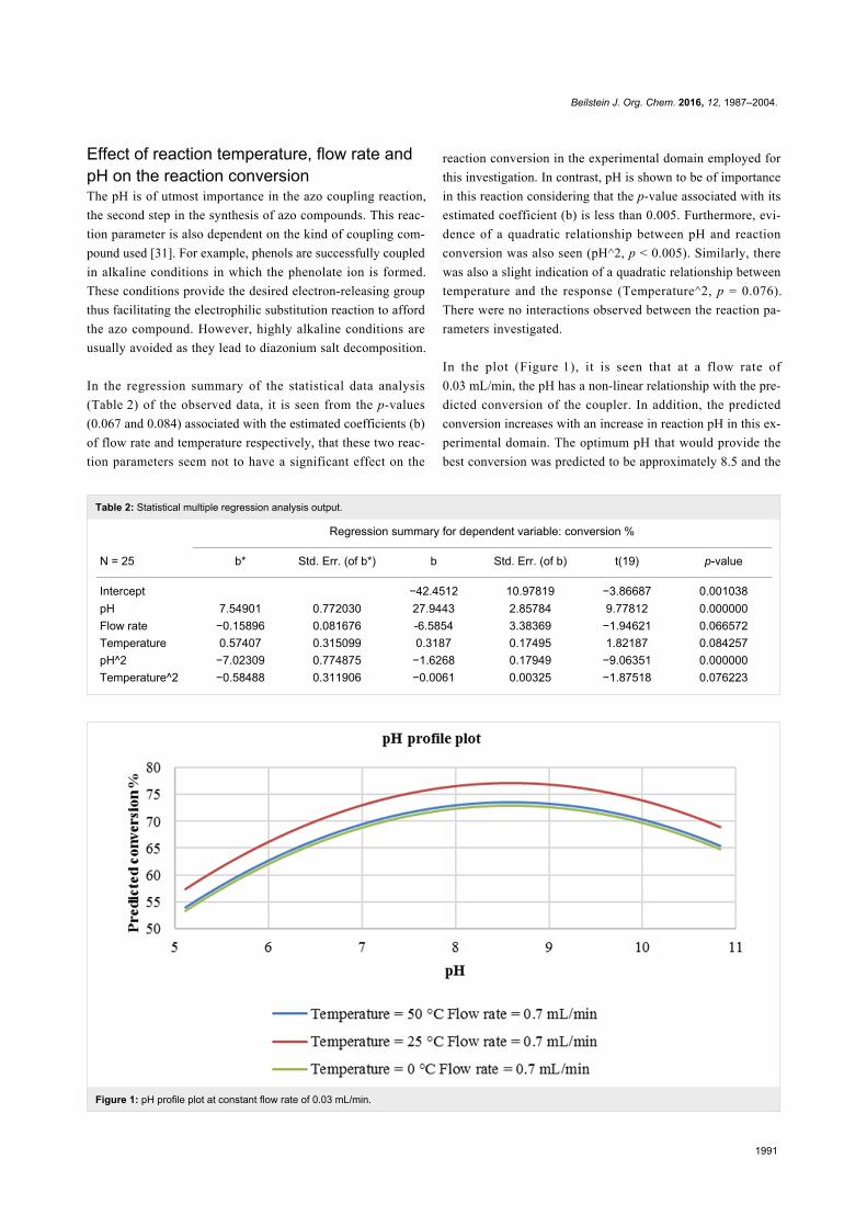
Table 2: Statistical multiple regression analysis output.
N = 25
Regression summary for dependent variable: conversion %
b* Std. Err. (of b*) b Std. Err. (of b) t(19) p-value
Intercept −42.4512 10.97819 −3.86687 0.001038pH 7.54901 0.772030 27.9443 2.85784 9.77812 0.000000Flow rate −0.15896 0.081676 -6.5854 3.38369 −1.94621 0.066572Temperature 0.57407 0.315099 0.3187 0.17495 1.82187 0.084257pH^2 −7.02309 0.774875 −1.6268 0.17949 −9.06351 0.000000Temperature^2 −0.58488 0.311906 −0.0061 0.00325 −1.87518 0.076223
Figure 1: pH profile plot at constant flow rate of 0.03 mL/min.
Effect of reaction temperature, flow rate andpH on the reaction conversionThe pH is of utmost importance in the azo coupling reaction,
the second step in the synthesis of azo compounds. This reac-
tion parameter is also dependent on the kind of coupling com-
pound used [31]. For example, phenols are successfully coupled
in alkaline conditions in which the phenolate ion is formed.
These conditions provide the desired electron-releasing group
thus facilitating the electrophilic substitution reaction to afford
the azo compound. However, highly alkaline conditions are
usually avoided as they lead to diazonium salt decomposition.
In the regression summary of the statistical data analysis
(Table 2) of the observed data, it is seen from the p-values
(0.067 and 0.084) associated with the estimated coefficients (b)
of flow rate and temperature respectively, that these two reac-
tion parameters seem not to have a significant effect on the
reaction conversion in the experimental domain employed for
this investigation. In contrast, pH is shown to be of importance
in this reaction considering that the p-value associated with its
estimated coefficient (b) is less than 0.005. Furthermore, evi-
dence of a quadratic relationship between pH and reaction
conversion was also seen (pH^2, p < 0.005). Similarly, there
was also a slight indication of a quadratic relationship between
temperature and the response (Temperature^2, p = 0.076).
There were no interactions observed between the reaction pa-
rameters investigated.
In the plot (Figure 1), it is seen that at a flow rate of
0.03 mL/min, the pH has a non-linear relationship with the pre-
dicted conversion of the coupler. In addition, the predicted
conversion increases with an increase in reaction pH in this ex-
perimental domain. The optimum pH that would provide the
best conversion was predicted to be approximately 8.5 and the

Beilstein J. Org. Chem. 2016, 12, 1987–2004.
1992
Figure 2: pH profile plot at a constant flow rate of 0.7 mL/min.
most suitable reaction temperature was found to be 25 °C.
Therefore, at a pH of about 8.5 and a reaction temperature of
25 °C, a reaction conversion of approximately 80% should be
attained. As expected, at highly alkaline conditions (pH 9–11),
the reaction conversion is predicted to gradually decrease. It is
also seen that at 0 °C and 50 °C, slightly lower conversion is
predicted (approximately 74%–75%). This could be attributed
to decomposition of the reaction intermediate at higher tempera-
tures (50 °C) and lowered rate of reaction at lower tempera-
tures (0 °C).
At a higher flow rate of 0.7 mL/min (Figure 2), a similar trend
is observed with regard to the effect of pH on the reaction
conversion. Similarly, a reaction temperature of 25 °C was pre-
dicted to provide optimum conversion (75%). At this reaction
temperature (25 °C), the predicted reaction conversion at this
flow rate, is slightly lower (75%) compared to that predicted at
a flow rate of 0.03 mL/min (80%). It was then concluded that
the flow rate of the reactants in this experimental domain had
no significant effect on the reaction response. For information,
this flow rate range covers a residence time of 0.37 to
0.86 minutes.
Azo coupling reaction in the synthesis of4-(2-(4-nitrophenyl)diazenyl)-N-phenyl-benzenamine in LTF-MS microreactorsThe synthesis of azo compounds involving couplers containing
aminated aromatic systems is usually carried out in slightly
acidic reaction conditions. The synthesis of 4-(2-(4-nitrophen-
yl)diazenyl)-N-phenylbenzenamine was an interesting choice
for demonstrating the synthesis of azo compounds involving
couplers containing aminated aromatic systems.
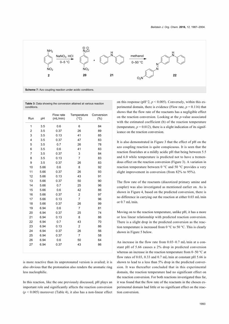
It involves the diazotization of p-nitroaniline 2 to form 20
which is subsequently coupled to 21. Diphenylamine (21), the
coupler used in this reaction is sparingly soluble in aqueous
media thus rendering it quite difficult to use in this synthesis
and as such, methanol was used as the azo coupling reaction
media (Scheme 7). It is due to this that the pH of the diazonium
compound solution was buffered to the preferred values for the
reaction investigation as opposed to the conventional buffering
of the coupler solution. Following the experimental procedures,
a range of reaction conditions were evaluated (Table 3).
A Logit model was then fitted onto the resultant calculated
conversions of diphenylamine as obtained from reversed phase
HPLC analysis output. STATISCA 12 – Statsoft program was
thereafter used to validate the model fitted (see Supporting
Information File 1). The result of this investigation is also
presented here in form of simple profile plots.
Effect of reaction pH, temperature and flowrate on the reaction conversionAzo coupling reactions involving aromatic amines as coupling
agents are carried out in mildly acidic conditions such that a
water-soluble protonated version of the aromatic amine, which
Beilstein J. Org. Chem. 2016, 12, 1987–2004.
1993
Scheme 7: Azo coupling reaction under acidic conditions.
Table 3: Data showing the conversion attained at various reactionconditions.
Run pHFlow rate(mL/min)
Temperature(°C)
Conversion(%)
1 3.5 0.6 6 842 3.5 0.37 26 893 3.5 0.13 41 854 3.5 0.37 47 835 3.5 0.7 26 786 3.5 0.6 41 837 3.5 0.37 3 848 3.5 0.13 7 839 3.5 0.37 26 83
10 5.66 0.6 8 9211 5.66 0.37 26 9312 5.66 0.13 43 9113 5.66 0.37 50 9014 5.66 0.7 25 9615 5.66 0.6 42 8616 5.66 0.37 2 9717 5.66 0.13 7 9618 5.66 0.37 26 9919 6.94 0.6 7 8120 6.94 0.37 25 7421 6.94 0.13 8 8622 6.94 0.7 43 7023 6.94 0.13 2 8624 6.94 0.37 26 5625 6.94 0.37 7 5826 6.94 0.6 50 6427 6.94 0.37 43 86
is more reactive than its unprotonated version is availed; it is
also obvious that the protonation also renders the aromatic ring
less nucleophilic.
In this reaction, like the one previously discussed, pH plays an
important role and significantly affects the reaction conversion
(p < 0.005) moreover (Table 4), it also has a non-linear effect
on this response (pH^2, p < 0.005). Conversely, within this ex-
perimental domain, there is evidence (Flow rate, p = 0.116) that
shows that the flow rate of the reactants has a negligible effect
on the reaction conversion. Looking at the p-value associated
with the estimated coefficient (b) of the reaction temperature
(temperature, p = 0.012), there is a slight indication of its signif-
icance on the reaction conversion.
It is also demonstrated in Figure 3 that the effect of pH on the
azo coupling reaction is quite conspicuous. It is seen that the
reaction flourishes at a mildly acidic pH that being between 5.5
and 6.0 while temperature is predicted not to have a tremen-
dous effect on the reaction conversion (Figure 3). A variation in
reaction temperature between 0 °C and 50 °C provides a very
slight improvement in conversion (from 82% to 95%).
The flow rate of the reactants (diazotized primary amine and
coupler) was also investigated as mentioned earlier on. As is
shown in Figure 4, based on the predicted conversion, there is
no difference in carrying out the reaction at either 0.03 mL/min
or 0.7 mL/min.
Moving on to the reaction temperature, unlike pH, it has a more
or less linear relationship with predicted reaction conversion.
There is a slight drop in the predicted conversion as the reac-
tion temperature is increased from 0 °C to 50 °C. This is clearly
shown in Figure 5 below.
An increase in the flow rate from 0.03–0.7 mL/min at a con-
stant pH of 5.66 causes a 2% drop in predicted conversion
whereas an increase in the reaction temperature from 0–50 °C at
flow rates of 0.03, 0.33 and 0.7 mL/min at constant pH 5.66 is
shown to lead to a less than 5% drop in the predicted conver-
sion. It was thereafter concluded that in this experimental
domain, the reaction temperature had no significant effect on
the reaction conversion. For both reactions investigated thus far,
it was found that the flow rate of the reactants in the chosen ex-
perimental domain had little or no significant effect on the reac-
tion conversion.

Beilstein J. Org. Chem. 2016, 12, 1987–2004.
1994
Table 4: Statistical multiple regression analysis output.
N = 24
Regression summary for dependent variable: logit
b* Std. Err. (of b*) b Std. Err. (of b) t(19) p-value
Intercept 8.14853 1.409724 5.78023 0.000014pH −9.27407 1.208038 −4.48258 0.583899 −7.67697 0.000000Temperature 0.29741 0.107162 0.01204 0.004340 2.77534 0.012053Flow rate 0.17639 0.107167 0.61041 0.370851 1.64596 0.116214pH^2 9.30475 1.208036 0.43744 0.056793 7.70238 0.000000
Figure 3: pH profile plot at a constant flow rate of 0.03 mL/min.
The effect of reaction parameters i.e. flow rate, temperature and
pH on azo coupling reactions in the synthesis of azo com-
pounds under acidic and alkaline reaction conditions in LTF-
MS microreactors however, was successfully demonstrated. We
therefore went ahead to fully make good use of the benefits that
microreactor technology offers to organic syntheses such as this
one by performing both reaction steps in continuous flow reac-
tors.
Continuous flow synthesis of Sudan II azodye in LTF-MS microreactorsHaving determined the reaction parameters that affect the azo
coupling reaction in the synthesis of Sudan II azo dye, an
attempt to perform both reaction steps involved in this synthe-
sis in continuous flow reactors was thus made. This was
achieved in LTF-MS reactors with the aid of statistical
modeling where the continuous flow synthesis of Sudan II azo
dye was optimized and used a model reaction.
Based on the statistical experimental central composite design
used for the optimization of this synthesis, no descriptive trends
showing the effect of the flow rates of reactants on the conver-
sion of 2-naphthol could be obtained. At all varied reaction pa-
rameters in the 20 experiments carried out, the response was
relatively the same with no clear cut trends observed as is
shown in Table 5. A quadratic regression model was then fitted

Beilstein J. Org. Chem. 2016, 12, 1987–2004.
1995
Figure 4: pH profile plot at constant flow rate of 0.7 mL/min.
Figure 5: Temperature profile plot at constant pH 5.66.
onto the observed data and no outliers were found during this
model fitting procedure in addition, there were also no indica-
tions of either synergistic or antagonist interactions between the
independent variables (see Supporting Information File 1). On
further statistical analysis of this data, it was found that there is
some evidence that supports the notion that the flow rate of the
Beilstein J. Org. Chem. 2016, 12, 1987–2004.
1996
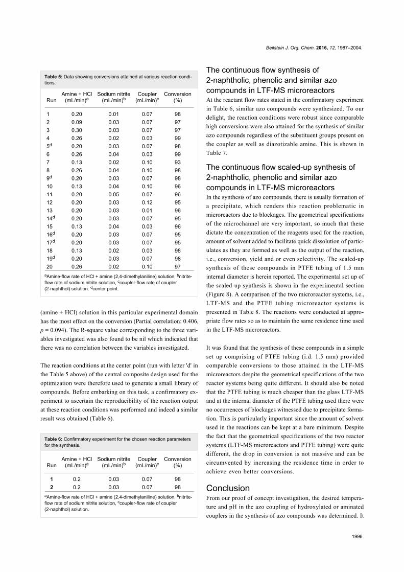
Table 5: Data showing conversions attained at various reaction condi-tions.
RunAmine + HCl
(mL/min)aSodium nitrite
(mL/min)bCoupler
(mL/min)cConversion
(%)
1 0.20 0.01 0.07 982 0.09 0.03 0.07 973 0.30 0.03 0.07 974 0.26 0.02 0.03 995d 0.20 0.03 0.07 986 0.26 0.04 0.03 997 0.13 0.02 0.10 938 0.26 0.04 0.10 989d 0.20 0.03 0.07 9810 0.13 0.04 0.10 9611 0.20 0.05 0.07 9612 0.20 0.03 0.12 9513 0.20 0.03 0.01 9614d 0.20 0.03 0.07 9515 0.13 0.04 0.03 9616d 0.20 0.03 0.07 9517d 0.20 0.03 0.07 9518 0.13 0.02 0.03 9819d 0.20 0.03 0.07 9820 0.26 0.02 0.10 97
aAmine-flow rate of HCl + amine (2,4-dimethylaniline) solution, bnitrite-flow rate of sodium nitrite solution, ccoupler-flow rate of coupler(2-naphthol) solution. dcenter point.
(amine + HCl) solution in this particular experimental domain
has the most effect on the conversion (Partial correlation: 0.406,
p = 0.094). The R-square value corresponding to the three vari-
ables investigated was also found to be nil which indicated that
there was no correlation between the variables investigated.
The reaction conditions at the center point (run with letter 'd' in
the Table 5 above) of the central composite design used for the
optimization were therefore used to generate a small library of
compounds. Before embarking on this task, a confirmatory ex-
periment to ascertain the reproducibility of the reaction output
at these reaction conditions was performed and indeed a similar
result was obtained (Table 6).
Table 6: Confirmatory experiment for the chosen reaction parametersfor the synthesis.
RunAmine + HCl
(mL/min)aSodium nitrite
(mL/min)bCoupler
(mL/min)cConversion
(%)
1 0.2 0.03 0.07 982 0.2 0.03 0.07 98
aAmine-flow rate of HCl + amine (2,4-dimethylaniline) solution, bnitrite-flow rate of sodium nitrite solution, ccoupler-flow rate of coupler(2-naphthol) solution.
The continuous flow synthesis of2-naphtholic, phenolic and similar azocompounds in LTF-MS microreactorsAt the reactant flow rates stated in the confirmatory experiment
in Table 6, similar azo compounds were synthesized. To our
delight, the reaction conditions were robust since comparable
high conversions were also attained for the synthesis of similar
azo compounds regardless of the substituent groups present on
the coupler as well as diazotizable amine. This is shown in
Table 7.
The continuous flow scaled-up synthesis of2-naphtholic, phenolic and similar azocompounds in LTF-MS microreactorsIn the synthesis of azo compounds, there is usually formation of
a precipitate, which renders this reaction problematic in
microreactors due to blockages. The geometrical specifications
of the microchannel are very important, so much that these
dictate the concentration of the reagents used for the reaction,
amount of solvent added to facilitate quick dissolution of partic-
ulates as they are formed as well as the output of the reaction,
i.e., conversion, yield and or even selectivity. The scaled-up
synthesis of these compounds in PTFE tubing of 1.5 mm
internal diameter is herein reported. The experimental set up of
the scaled-up synthesis is shown in the experimental section
(Figure 8). A comparison of the two microreactor systems, i.e.,
LTF-MS and the PTFE tubing microreactor systems is
presented in Table 8. The reactions were conducted at appro-
priate flow rates so as to maintain the same residence time used
in the LTF-MS microreactors.
It was found that the synthesis of these compounds in a simple
set up comprising of PTFE tubing (i.d. 1.5 mm) provided
comparable conversions to those attained in the LTF-MS
microreactors despite the geometrical specifications of the two
reactor systems being quite different. It should also be noted
that the PTFE tubing is much cheaper than the glass LTF-MS
and at the internal diameter of the PTFE tubing used there were
no occurrences of blockages witnessed due to precipitate forma-
tion. This is particularly important since the amount of solvent
used in the reactions can be kept at a bare minimum. Despite
the fact that the geometrical specifications of the two reactor
systems (LTF-MS microreactors and PTFE tubing) were quite
different, the drop in conversion is not massive and can be
circumvented by increasing the residence time in order to
achieve even better conversions.
ConclusionFrom our proof of concept investigation, the desired tempera-
ture and pH in the azo coupling of hydroxylated or aminated
couplers in the synthesis of azo compounds was determined. It

Beilstein J. Org. Chem. 2016, 12, 1987–2004.
1997
Table 7: Azo compounds synthesized under alkaline and acidic azo coupling conditions.
Run Diazotizable amine Coupler Product Conversion
1 97%
2 88%
3 95%
4 80%
5 92%
6 80%
7 88%
8 84%
Beilstein J. Org. Chem. 2016, 12, 1987–2004.
1998
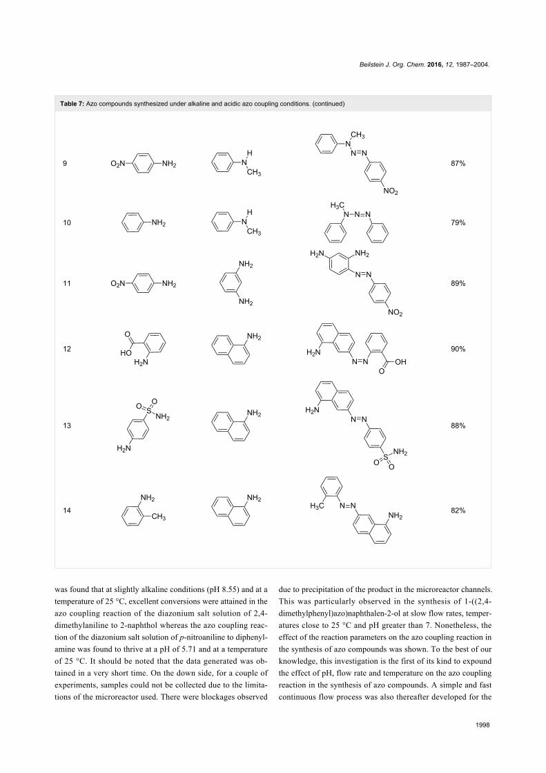
Table 7: Azo compounds synthesized under alkaline and acidic azo coupling conditions. (continued)
9 87%
10 79%
11 89%
12 90%
13 88%
14 82%
was found that at slightly alkaline conditions (pH 8.55) and at a
temperature of 25 °C, excellent conversions were attained in the
azo coupling reaction of the diazonium salt solution of 2,4-
dimethylaniline to 2-naphthol whereas the azo coupling reac-
tion of the diazonium salt solution of p-nitroaniline to diphenyl-
amine was found to thrive at a pH of 5.71 and at a temperature
of 25 °C. It should be noted that the data generated was ob-
tained in a very short time. On the down side, for a couple of
experiments, samples could not be collected due to the limita-
tions of the microreactor used. There were blockages observed
due to precipitation of the product in the microreactor channels.
This was particularly observed in the synthesis of 1-((2,4-
dimethylphenyl)azo)naphthalen-2-ol at slow flow rates, temper-
atures close to 25 °C and pH greater than 7. Nonetheless, the
effect of the reaction parameters on the azo coupling reaction in
the synthesis of azo compounds was shown. To the best of our
knowledge, this investigation is the first of its kind to expound
the effect of pH, flow rate and temperature on the azo coupling
reaction in the synthesis of azo compounds. A simple and fast
continuous flow process was also thereafter developed for the

Beilstein J. Org. Chem. 2016, 12, 1987–2004.
1999
Table 8: Comparison of reaction conversion attained from two continuous flow reactor systems.
Run Diazotizable amine Coupler Product Conversion
LTF-MS(CD: 1.0 mm)
PTFE(i.d.: 1.5 mm)
1 97% 90%
2 88% 91%
3 95% 69%
4 80% 71%
5 92% 70%
6 80% 70%
7 88% 67%
8 89% 80%

Beilstein J. Org. Chem. 2016, 12, 1987–2004.
2000
Table 8: Comparison of reaction conversion attained from two continuous flow reactor systems. (continued)
9 90% 72%
10 88% 78%
11 82% 66%
synthesis of naphtholic, phenolic and similar azo dyes. The
robustness of the process was clearly demonstrated. In addition,
an easy scale-up strategy was also established where it was
found that the synthesis of these compounds in a simple contin-
uous flow set up consisting of T-mixers and PTFE tubing (i.d.:
1.5 mm) provided relatively satisfactory reaction conversions
moreover no occurrence of blockages was observed when this
set up was in use. This finding is of importance especially when
it comes to an increasing reaction throughput by the numbering
up technique. Ideally, in evaluating the performance of two
reactor systems in a chemical synthesis, it is important to keep
most factors constant especially those pertaining to the geome-
try of the reactor channel as this can affect the reaction output.
Albeit comparable reaction conversions were attained from the
two reactor systems investigated, it is worth determining the
role that the difference in geometrical structure had to play in
the data observed in this study.
ExperimentalAll chemicals and solvents used were of analytical grade. 1H
and 13C NMR spectra were recorded on a Bruker Avance-400
(400 MHz).
Microreactor set up; azo coupling reactions inthe synthesis of azo compoundsUsing two (1 mL) SGE glass syringes and PTFE tubing of
0.5 mm internal diameter, the reactants (diazonium salt and azo
coupling component solutions) were fed to an LTF-MS
(Volume: 0.2 mL, channel size: 1 mm, geometry: 115 × 60 ×
6 mm) microreactor plate (Figure 6). The microreactor plate
was dipped into a temperature control bath and delivery of the
reactants to the plates was enabled by two Chemyx fusion 100
classic syringe pumps.
Figure 6: Schematic representation of the microreactor set up.
Preparation of reactant solutionsSolution A (diazotized primary aromatic amine): 2,4-dimethyl-
aniline (0.2918 g) was dissolved in approximately 0.8 mL of
Beilstein J. Org. Chem. 2016, 12, 1987–2004.
2001
concentrated 32% HCl and cooled. To this cooled solution,
3 mL of cold sodium nitrite solution (0.29 g in 5 mL of distilled
water) was added drop wise until the potassium starch iodide
paper test was positive. DMF (20 mL) was added to this, after
which the solution was made up to a volume (100 mL) with
distilled water.
Solution B (coupler): 2-naphthol (0.35 g) was dissolved in 10%
aqueous NaOH (10 mL) to which DMF (15 mL) was added.
The pH of the solution was buffered to the appropriate pH
intended for the investigation (pH 5.11, 7.39 and 10.83). The
solution was then made up to a volume (50 mL) with distilled
water.
Similarly, the reactant solutions A and B (diazotized primary ar-
omatic amine and coupler) in the azo coupling of diazonium salt
solution of p-nitroaniline to diphenylamine were prepared as
follows:
Solution A (diazotized primary aromatic amine): p-nitroaniline
(0.2918 g) was dissolved in hot concentrated 32% HCl (0.8 mL)
and cooled. To this cooled solution, cold sodium nitrite solu-
tion (0.29 g in 5 mL of distilled water) was added drop wise
until the potassium starch iodide paper test was positive. DMF
(20 mL) was added to this after which the pH of the solution
was buffered to afford the various working pH intended for the
study (pH: 3.5, 5.66 and 6.94). The solution was then made up
to a volume (100 mL) with distilled water.
Solution B (coupler): diphenylamine (0.35 g) was dissolved in
methanol (50 mL).
Azo coupling reactions in microreactorsA central composite experimental design with a total of 12 ex-
periments was used for each of the optimization studies at the
various pH levels for the two reactions. The experiments were
performed in a randomized manner. In addition, the flow rate of
the solutions A and B was also varied as is shown in Table 9
below. The temperature of the batch diazotization reaction was
kept constant at 0 °C while that of the azo coupling reaction.
Table 9: Experimental domain.
Reaction parameters Minimum Maximum
Flow rate (mL/min) 0.03 0.7Temperature (°C) 0 50
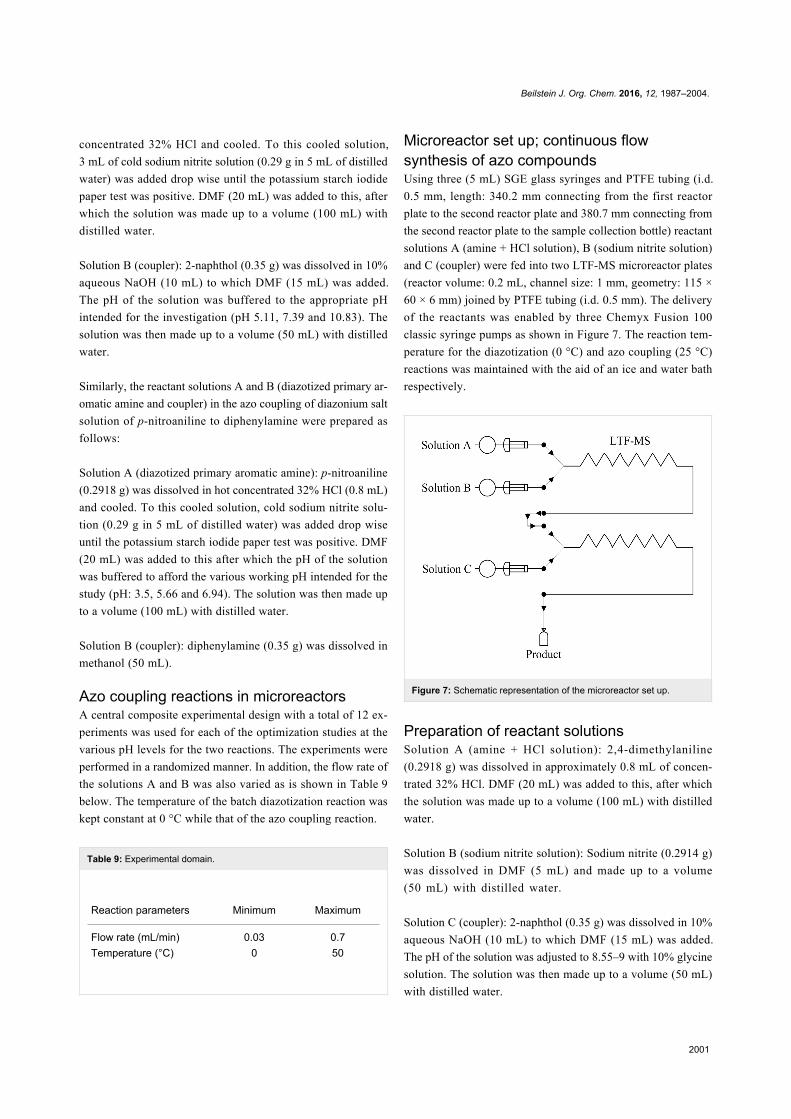
Microreactor set up; continuous flowsynthesis of azo compoundsUsing three (5 mL) SGE glass syringes and PTFE tubing (i.d.
0.5 mm, length: 340.2 mm connecting from the first reactor
plate to the second reactor plate and 380.7 mm connecting from
the second reactor plate to the sample collection bottle) reactant
solutions A (amine + HCl solution), B (sodium nitrite solution)
and C (coupler) were fed into two LTF-MS microreactor plates
(reactor volume: 0.2 mL, channel size: 1 mm, geometry: 115 ×
60 × 6 mm) joined by PTFE tubing (i.d. 0.5 mm). The delivery
of the reactants was enabled by three Chemyx Fusion 100
classic syringe pumps as shown in Figure 7. The reaction tem-
perature for the diazotization (0 °C) and azo coupling (25 °C)
reactions was maintained with the aid of an ice and water bath
respectively.
Figure 7: Schematic representation of the microreactor set up.
Preparation of reactant solutionsSolution A (amine + HCl solution): 2,4-dimethylaniline
(0.2918 g) was dissolved in approximately 0.8 mL of concen-
trated 32% HCl. DMF (20 mL) was added to this, after which
the solution was made up to a volume (100 mL) with distilled
water.
Solution B (sodium nitrite solution): Sodium nitrite (0.2914 g)
was dissolved in DMF (5 mL) and made up to a volume
(50 mL) with distilled water.
Solution C (coupler): 2-naphthol (0.35 g) was dissolved in 10%
aqueous NaOH (10 mL) to which DMF (15 mL) was added.
The pH of the solution was adjusted to 8.55–9 with 10% glycine
solution. The solution was then made up to a volume (50 mL)
with distilled water.
Beilstein J. Org. Chem. 2016, 12, 1987–2004.
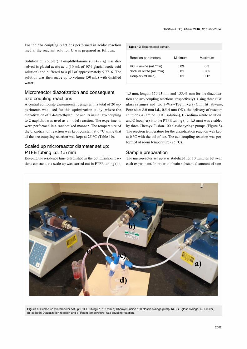
2002
Figure 8: Scaled up microreactor set up: PTFE tubing i.d. 1.5 mm a) Chemyx Fusion 100 classic syringe pump, b) SGE glass syringe, c) T-mixer,d) Ice bath: Diazotization reaction and e) Room temperature: Azo coupling reaction.
For the azo coupling reactions performed in acidic reaction
media, the reactant solution C was prepared as follows.
Solution C (coupler): 1-naphthylamine (0.3477 g) was dis-
solved in glacial acetic acid (10 mL of 10% glacial acetic acid
solution) and buffered to a pH of approximately 5.77–6. The
solution was then made up to volume (50 mL) with distilled
water.
Microreactor diazotization and consequentazo coupling reactionsA central composite experimental design with a total of 20 ex-
periments was used for this optimization study, where the
diazotization of 2,4-dimethylaniline and its in situ azo coupling
to 2-naphthol was used as a model reaction. The experiments
were performed in a randomized manner. The temperature of
the diazotization reaction was kept constant at 0 °C while that
of the azo coupling reaction was kept at 25 °C (Table 10).
Scaled up microreactor diameter set up:PTFE tubing i.d. 1.5 mmKeeping the residence time established in the optimization reac-
tions constant, the scale up was carried out in PTFE tubing (i.d.
Table 10: Experimental domain.
Reaction parameters Minimum Maximum
HCl + amine (mL/min) 0.09 0.3Sodium nitrite (mL/min) 0.01 0.05Coupler (mL/min) 0.01 0.12
1.5 mm, length: 150.93 mm and 155.43 mm for the diazotiza-
tion and azo coupling reactions, respectively). Using three SGE
glass syringes and two 3-Way-Tee mixers (Omnifit labware,
Pore size: 8.0 mm i.d., 0.5-4 mm OD), the delivery of reactant
solutions A (amine + HCl solution), B (sodium nitrite solution)
and C (coupler) into the PTFE tubing (i.d. 1.5 mm) was enabled
by three Chemyx Fusion 100 classic syringe pumps (Figure 8).
The reaction temperature for the diazotization reaction was kept
at 0 °C with the aid of ice. The azo coupling reaction was per-
formed at room temperature (25 °C).
Sample preparationThe microreactor set up was stabilized for 10 minutes between
each experiment. In order to obtain substantial amount of sam-

Beilstein J. Org. Chem. 2016, 12, 1987–2004.
2003
ples for analysis, they were collected for a period of 1 minute
each in a sample vial containing HCl (0.2 mL of 1 M). The mix-
ture was then diluted with DMF (1 mL).
Sample analysisOff-line reversed phase HPLC using a Phenomenex Luna 5 µ
C18 100 A (250 × 4.60 mm × 5 microns) column under the
following conditions; flow rate: 1.2 mL/min, mobile phase
(acetonitrile 0.1% formic acid (75:25)) equipped with a vari-
able wavelength detector was used for sample analysis. The
external standard calibration HPLC method was used to quan-
tify the amount of coupler utilized in the reaction. The wave-
length used for quantification of the 2-naphthol was 349 nm.
Data analysisThe total volume of samples collected (tvscollected) was calcu-
lated by multiplying the total flow rate of the reactant solutions
(tfrABC) by the total sample collection time (tcollection). The
reaction time was calculated by dividing the total reaction space
volume i.e. the total volume of the two LTF-MS plates, the
PTFE tubing used to join the two mixers and also that leading to
the final outlet: the point of sample collection by the total flow
rate of reactant solutions (tfrABC). For purposes of data analysis,
all flow rates were converted to liters/minute.
Supporting InformationSupporting Information File 1Additional diagrams and NMR spectra.
[http://www.beilstein-journals.org/bjoc/content/
supplementary/1860-5397-12-186-S1.pdf]
AcknowledgementsWe would like to thank the South African National Research
Foundation, InnoVenton and Nelson Mandela Metropolitan
University for the financial support and Mr Coos Bosma for
statistical support.
References1. James, C. H. In Handbook of Green Chemistry and Technology;
Clark, J.; Macquarrie, D., Eds.; John Wiley & Sons, Ltd., 2002;pp 10–27.
2. Anastas, P.; Eghbali, N. Chem. Soc. Rev. 2009, 39, 301–312.doi:10.1039/b918763b
3. Noroozi-Pesyan, N.; Khalafy, J.; Malekpoor, Z.Prog. Color, Color. Coat. 2009, 2, 61–70.
4. Rahimizadeh, M.; Eshghi, H.; Shiri, A.; Ghadamyari, Z.; Matin, M. M.;Oroojalian, F.; Pordeli, P. J. Korean Chem. Soc. 2012, 56, 716–719.doi:10.5012/jkcs.2012.56.6.716
5. Mirjalili, F. B. B.; Bamoniri, A.; Akbari, A. Curr. Chem. Lett. 2012, 1,109–114. doi:10.5267/j.ccl.2012.6.002
6. Bamoniri, A.; Pourali, A. R.; Nazifi, M. R. S. Iran. J. Catal. 2012, 2,185–189.
7. Caldarelli, M.; Baxendale, I. R.; Ley, S. V. Green Chem. 2000, 2,259–264. doi:10.1039/b000816h
8. Grirrane, A.; Corma, A.; García, H. Science 2008, 322, 1661–1664.doi:10.1126/science.1166401
9. Zhao, R.; Tan, C.; Xie, Y.; Gao, C.; Liu, H.; Jiang, Y. Tetrahedron Lett.2011, 52, 3805–3809. doi:10.1016/j.tetlet.2011.05.054
10. Moglie, Y.; Vitale, C.; Radivoy, G. Tetrahedron Lett. 2008, 49,1828–1831. doi:10.1016/j.tetlet.2008.01.053
11. Velasco, M. I.; Kinen, C. O.; de Rossi, R. H.; Rossi, L. I. Dyes Pigm.2011, 90, 259–264. doi:10.1016/j.dyepig.2010.12.009
12. Damodaran, B.; Litka, J.; Lalithambika, M. Synth. Commun. 2003, 33,863–869. doi:10.1081/SCC-120016343
13. Valizadeh, H.; Amiri, M.; Shomali, A.; Hosseinzadeh, F.J. Iran. Chem. Soc. 2011, 8, 495–501. doi:10.1007/bf03249083
14. Qiao, R.-Z.; Zhang, Y.; Hui, X.-P.; Xu, P.-F.; Zhang, Z.-Y.; Wang, X.-Y.;Wang, Y.-L. Green Chem. 2001, 3, 186–188. doi:10.1039/b103840k
15. Dabbagh, H. A.; Teimouri, A.; Chermahini, A. N. Dyes Pigm. 2007, 73,239–244. doi:10.1016/j.dyepig.2005.12.002
16. Zarei, A.; Hajipour, A. R.; Khazdooz, L.; Mirjalili, B. F.;Chermahini, A. N. Dyes Pigm. 2009, 81, 240–244.doi:10.1016/j.dyepig.2008.10.011
17. Wootton, R. C. R.; Fortt, R.; de Mello, A. J. Lab Chip 2002, 2, 5–7.doi:10.1039/b111286d
18. Delville, M. M. E.; Nieuwland, P. J.; Janssen, P.; Koch, K.;Van Hest, J. C. M.; Rutjes, F. P. J. T. Chem. Eng. J. 2011, 167,556–559. doi:10.1016/j.cej.2010.08.087
19. Struempel, M.; Ondruschka, B.; Daute, R.; Stark, A. Green Chem.2008, 10, 41–43. doi:10.1039/b710554a
20. Chung, K.-T.J. Environ. Sci. Health, Part C: Environ. Carcinog. Ecotoxicol. Rev.2000, 18, 51–74. doi:10.1080/10590500009373515
21. Wang, C.; Yediler, A.; Lienert, D.; Wang, Z.; Kettrup, A. Chemosphere2002, 46, 339–344. doi:10.1016/s0045-6535(01)00086-8
22. Rai, H. S.; Bhattacharyya, M. S.; Singh, J.; Bansal, T. K.; Vats, P.;Banerjee, U. C. Crit. Rev. Environ. Sci. Technol. 2005, 35, 219–238.doi:10.1080/10643380590917932
23. Hisamoto, H.; Saito, T.; Tokeshi, M.; Hibara, A.; Kitamori, T.Chem. Commun. 2001, 2662–2663. doi:10.1039/b106494k
24. Wille, C.; Gabski, H.-P.; Haller, T.; Kim, H.; Unverdorben, L.; Winter, R.Chem. Eng. J. 2004, 101, 179–185. doi:10.1016/j.cej.2003.11.007
25. Pennemann, H.; Forster, S.; Kinkel, J.; Hessel, V.; Löwe, H.; Wu, L.Org. Process Res. Dev. 2005, 9, 188–192. doi:10.1021/op049789e
26. Anderson, N. G. Org. Process Res. Dev. 2012, 16, 852–869.doi:10.1021/op200347k
27. De Zani, D.; Colombo, M. J. Flow Chem. 2012, 2, 5–7.doi:10.1556/jfchem.2012.00020
28. Webb, D.; Jamison, T. F. Chem. Sci. 2010, 1, 675–680.doi:10.1039/c0sc00381f
29. Newman, S. G.; Jensen, K. F. Green Chem. 2013, 15, 1456–1472.doi:10.1039/c3gc40374b
30. Martin, L. J.; Marzinzik, A. L.; Ley, S. V.; Baxendale, I. R. Org. Lett.2011, 13, 320–323. doi:10.1021/ol1027927
31. Christie, R. M. Colour Chemistry. The Royal Society of Chemistry:Thomas Graham House., 2001; pp 51–55.

Beilstein J. Org. Chem. 2016, 12, 1987–2004.
2004
License and TermsThis is an Open Access article under the terms of the
Creative Commons Attribution License
(http://creativecommons.org/licenses/by/4.0), which
permits unrestricted use, distribution, and reproduction in
any medium, provided the original work is properly cited.
The license is subject to the Beilstein Journal of Organic
Chemistry terms and conditions:
(http://www.beilstein-journals.org/bjoc)
The definitive version of this article is the electronic one
which can be found at:
doi:10.3762/bjoc.12.186


![UvA-DARE (Digital Academic Repository) Development of catalytic microreactors … · “packed-bed” microreactors [270], the insertion of palladium membranes inside microreactors](https://img.dokumen.tips/doc/110x75/5f38c6061a204d19f85d9277/uva-dare-digital-academic-repository-development-of-catalytic-microreactors-aoepacked-beda.jpg)