Embed Size (px)
Citation preview

The importance of aerodynamics and the role of aerodynamic measurements This paper was presented at The Science of making Torque 2012, 9-11 October 2012, Oldenburg, Germany J.G. Schepers S. Schreck (NREL)
February 2013 ECN-M--13-002
The importance of aerodynamics and the
role of aerodynamic measurements
Gerard Schepers (ECN) and Scott Schreck (NREL)
The science of Making Torque, Oldenburg
Illustrated with results from the NASA-Ames experiment at yaw
www.ecn.nl
The science of Making Torque, Oldenburg

Content
• Importance of wind turbine aerodynamics
– Aerodynamic design modelling
– Aerodynamic measurements
• Aerodynamic wind turbine measurements
– IEA projects on field and wind tunnel measurements– IEA projects on field and wind tunnel measurements(IEA Task 14, IEA Task 18, IEA Task 20 and IEA Task 29 (Mexnext-I))
• Power at yawed conditions in NASA-Ames measurements
– Current and future developments with regard to aerodynamic measurements
2

AERODYNAMICS OF WIND
TURBINES
Important for:
• Energy production• Loads (strength, costs!)• Stability (failure, damage)• Control• Stability (failure, damage)• Control
– Stall– (Individual) pitch– Distributed aerodynamic control
And hence the overall success of a wind turbine design
33-2-2013

AERODYNAMICS
• Aerodynamics of wind turbines is extremely difficult– Rotating– In lower part of atmosphere � extremely turbulent– Instationary– Stall(!)– Stall(!)– Large variety in scales (Diameter can be twice span of Airbus A380!)– Constraints and interactions (e.g. costs, system dynamics)– Wind turbine aerodynamic calculations are extremely time consuming
– Load calculations: Time domain, many long time series needed to get ‘statistics right’
– (~106 nr of time steps)� Calculational time of a design spectrum can easily belonger than lifetime of the wind turbine
– Generally calculations are done with simplified Blade Element Momentum (BEM) Theory with engineering add-ons to cover instationary effects, stall, 3D effects, yaw etc.
43-2-2013

Aerodynamic modelling
– Former validation projects generally show 10-20% accuracy of blade loads calculated with BEM for standard conditions, (excluding stall) but still large uncertainties (i.e. 50%) in off-design conditions 1)
– What about uncertainties for modern wind turbines?• Wind turbine designs become ‘unconventional’, what about the
modelling aspects?modelling aspects?
• Aerodynamic modelling of distributed control devices
• For very large turbines BEM may not model correctly:– Incoherent structures over the rotor– Extreme shear, low level jets, 3D shear effects (wind farms!)
– Research needed to improve the accuracy, among others by other types of modelling, e.g CFD
1) Schepers, J.G.; Heijdra, J.J.; Thomsen, K.; Larsen, T.; Foussekis, D.; Rawlinson Smith, R.; Kraan, I.; Visser, B.; Øye, S.; Ganander, H.; Carlen, I.; Voutsinas, S.; Belessis, M.; Drost, L. Verification of European Wind turbine design codes, presented at European wind energy conference and exhibition, Copenhagen, Denmark, 2-6 july, 2001.
5

Aerodynamics
•MEASUREMENTS , MEASUREMENTS, MEASUREMENTS
• Detailed aerodynamic measurements along the blades are urgently needed at several conditions
63-2-2013

Content
• Importance of wind turbine aerodynamics
– Aerodynamic design modelling
– Aerodynamic measurements
• Aerodynamic wind turbine measurements
– IEA projects on field and wind tunnel measurements– IEA projects on field and wind tunnel measurements(IEA Task 14, IEA Task 18, IEA Task 20 and IEA Task 29 (Mexnext-I))
• Power at yawed conditions in NASA-Ames measurements
– Current and future developments
7

IEA TASKS ON AERODYNAMIC
MEASUREMENTS
– 1991-1997: IEA Task 14 (Field Rotor Aerodynamics, Operating Agent: ECN)
– 1997-2001: IEA Task 18 (Field Rotor Aerodynamics, enhanced, Operating Agent: ECN))
– 2001-2007: IEA Task 20: (Analysis of NREL’s NASA-Ames, – 2001-2007: IEA Task 20: (Analysis of NREL’s NASA-Ames, measurements, Operating Agent: NREL)
– 2008-2011: IEA Task 29: Mexnext-I (Analysis of Mexico measurements, Operating Agent: ECN)
– 2011-2014: IEA Task 29: Mexnext-II (various measurements, Operating Agent, ECN)
8
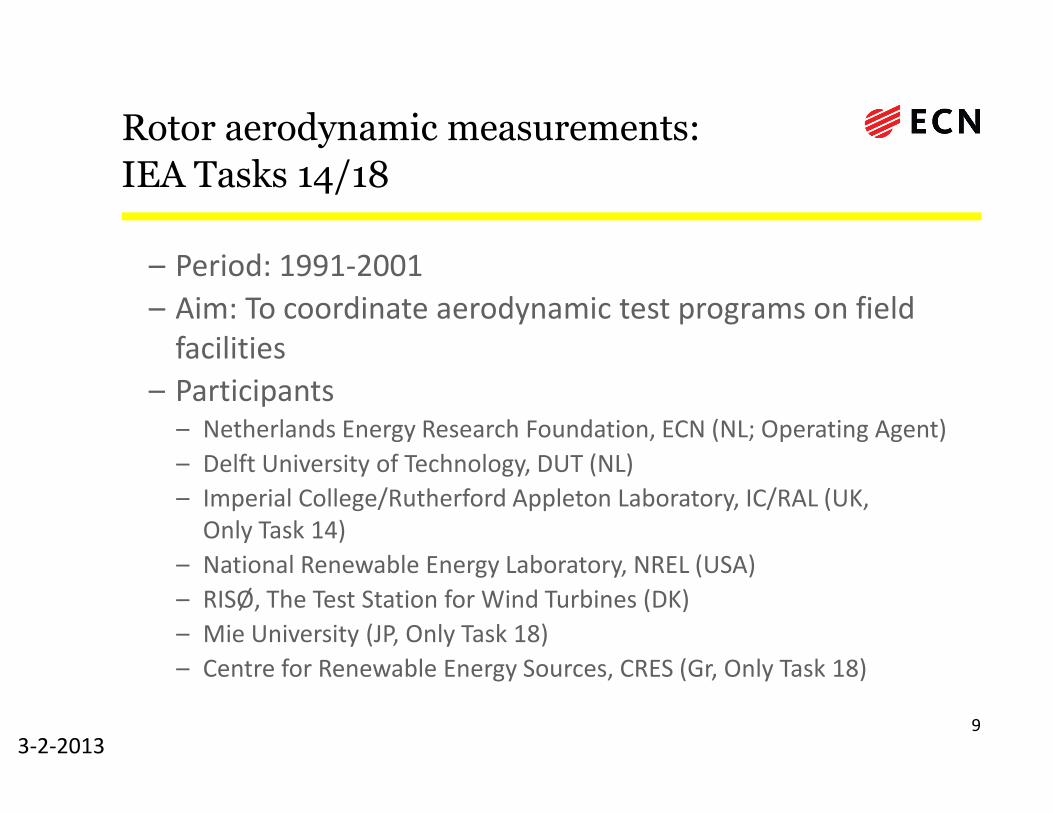
Rotor aerodynamic measurements:
IEA Tasks 14/18
– Period: 1991-2001
– Aim: To coordinate aerodynamic test programs on field facilities
– Participants– Participants– Netherlands Energy Research Foundation, ECN (NL; Operating Agent)
– Delft University of Technology, DUT (NL)
– Imperial College/Rutherford Appleton Laboratory, IC/RAL (UK, Only Task 14)
– National Renewable Energy Laboratory, NREL (USA)
– RISØ, The Test Station for Wind Turbines (DK)
– Mie University (JP, Only Task 18)
– Centre for Renewable Energy Sources, CRES (Gr, Only Task 18)
93-2-2013
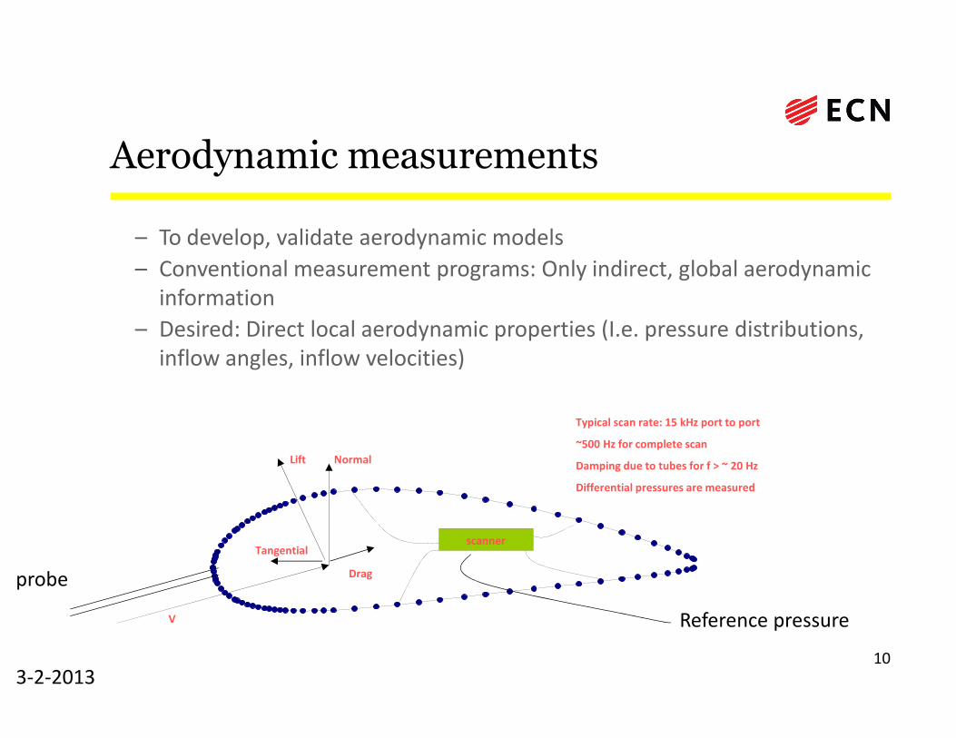
Aerodynamic measurements
– To develop, validate aerodynamic models
– Conventional measurement programs: Only indirect, global aerodynamic information
– Desired: Direct local aerodynamic properties (I.e. pressure distributions, inflow angles, inflow velocities)inflow angles, inflow velocities)
103-2-2013
Typical scan rate: 15 kHz port to port
~500 Hz for complete scan
Damping due to tubes for f > ~ 20 Hz
Differential pressures are measured
scanner
Lift Normal
Tangential
Drag
V
probe
Reference pressure

IEA Tasks 14/18: Facilities
113-2-2013
ECN facility NREL facility

IEA Task 14/18 some results
•Database on http://www.ecn.nl/nl/units/wind/projecten/field-rotor-aerodynamics-database/
•‘Discovery’ of •Stall delay on wind turbines (underprediction of loads at innerpart of the blade at large angles of attack when using 2D airfoil
123-2-2013
part of the blade at large angles of attack when using 2D airfoilcoefficients)
• Overprediction of tip loads when using 2D airfoil coefficients•‘Compensating’ errors when using global measurements
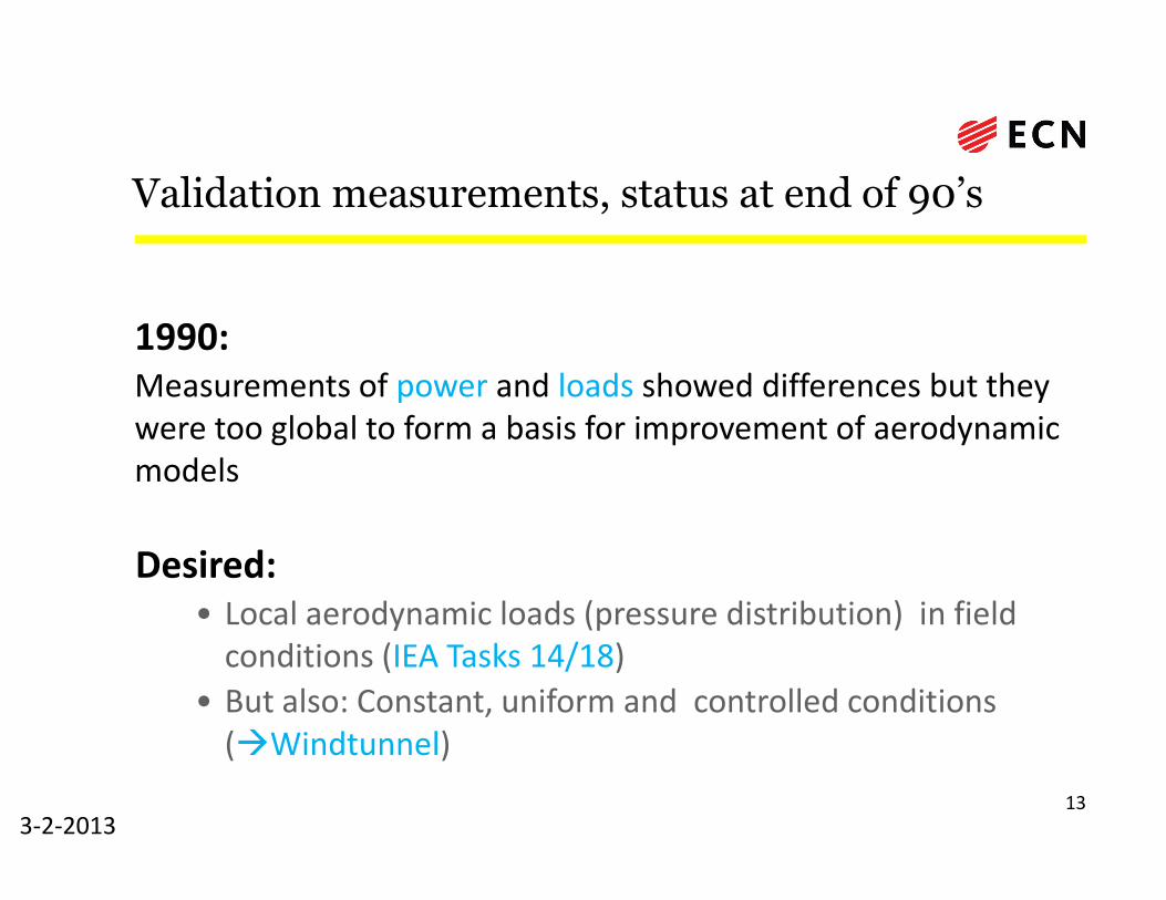
Validation measurements, status at end of 90’s
1990:
Measurements of power and loads showed differences but they were too global to form a basis for improvement of aerodynamic modelsmodels
Desired:
• Local aerodynamic loads (pressure distribution) in field conditions (IEA Tasks 14/18)
• But also: Constant, uniform and controlled conditions (�Windtunnel)
133-2-2013

Measurements in NASA-Ames wind tunnel
•Carried out by NREL (National Renewable Energy Laboratory), USA•Spring 2000 •24m x 36m NASA-Ames wind tunnel.•10 m rotor•Measurement of pressure distributions at 5 locationsalong rotor blade
143-2-2013
•Measurement of pressure distributions at 5 locationsalong rotor blade•Analysed in IEA Task 20 (Operating Agent: NREL)•Participants:
–ETS (Canada)–RISO/DTU (Denmark)–CRES/NTUA (Greece)–ECN/TUDelft (Holland)–IFE (Norway)–CENER (Spain)–HGO (Sweden)

Content
• Importance of wind turbine aerodynamics
– Aerodynamic design modelling
– Aerodynamic measurements
• Aerodynamic wind turbine measurements
– IEA projects on field and wind tunnel measurements– IEA projects on field and wind tunnel measurements(IEA Task 14, IEA Task 18, IEA Task 20 and IEA Task 29 (Mexnext-I))
• Power at yawed conditions in NASA-Ames measurements
– Current and future developments
15

Illustration of the value of
aerodynamic measurements
A study of the power at yawed conditions in NASA-Ames
Most of the attention (also in the IEA tasks) was focussed on loads at yawed conditions
• What happens with the power in yaw?
163-2-2013
• What happens with the power in yaw?
• It is proposed to assume a cosinuidal behaviour (inspired by 1) – P ~ P0cosxφy with P0 the power at zero yaw and x the exponent to be determined
1) Dahlberg, J.A. and Montgomerie, B Research program of the Utgrunden Demonstration Offshore Wind Farm, Final report Part 2, Wake
effects and other loads
Swedish Defense Research Agency, FOI, FOI 2005-02-17 , 2005

x = 3?
• Some people think that x = 3: P ~ P0cos3φy
based on the assumption that:– P ~ Vaxial
3
– V = V cos(φ )
173-2-2013
– Vaxial = Vw cos(φy)
– This (implicitly) assumes a constant induction with yaw angle
•However induction changes with yaw angle!

Research from Jan-Ake Dahlberg 1)
• Jan Ake Dahlberg (Vattenfall/FFA) finds on basis of field and wind tunnel measurements that:– P ~ P0cosxφy with x to vary between 1.88 and 5.15
– BEM overpredicts the power at yawed conditions
183-2-2013
1) Dahlberg, J.A. and Montgomerie, B Research program of the Utgrunden Demonstration Offshore Wind Farm, Final report Part 2, Wake effects and other loadsSwedish Defense Research Agency, FOI, FOI 2005-02-17 , 2005

DATA measurements on rotor with D=4.5 m in German
Dutch Wind Tunnel DNW at design conditions 1)
– P ~ P0cosxφy with x ~ 1.8
– BEM overpredicts the power at yawed conditions
�Generally consistent with findings from 2)
193-2-2013
1) J.G. Schepers EU project in German Dutch Wind Tunnel ECN-RX--01-006, 20012) Dahlberg, J.A. and Montgomerie, B Research program of the Utgrunden Demonstration Offshore Wind Farm, Final report Part 2, Wake effects and other loadsSwedish Defense Research Agency, FOI, FOI 2005-02-17 , 2005

Analysis on NREL Phase VI(NASA-Ames) P(φφφφy) measurements
Results analyzed at Vtun = 5, 10 and 15 m/s and θ = 0, 3 and 6 degrees
Vtun=5m/s: Power decreases with yaw
20
• Trend: Power decrease with yaw seems less apparent for larger angles of attack (high wind speed and low pitch angle) and eventually the power even increases withyaw!
Vtun=10m/s: Power decreases with yaw for θ =6 degincreases with yaw for θ = 0 deg
Vtun=15m/s: Power increases with yaw
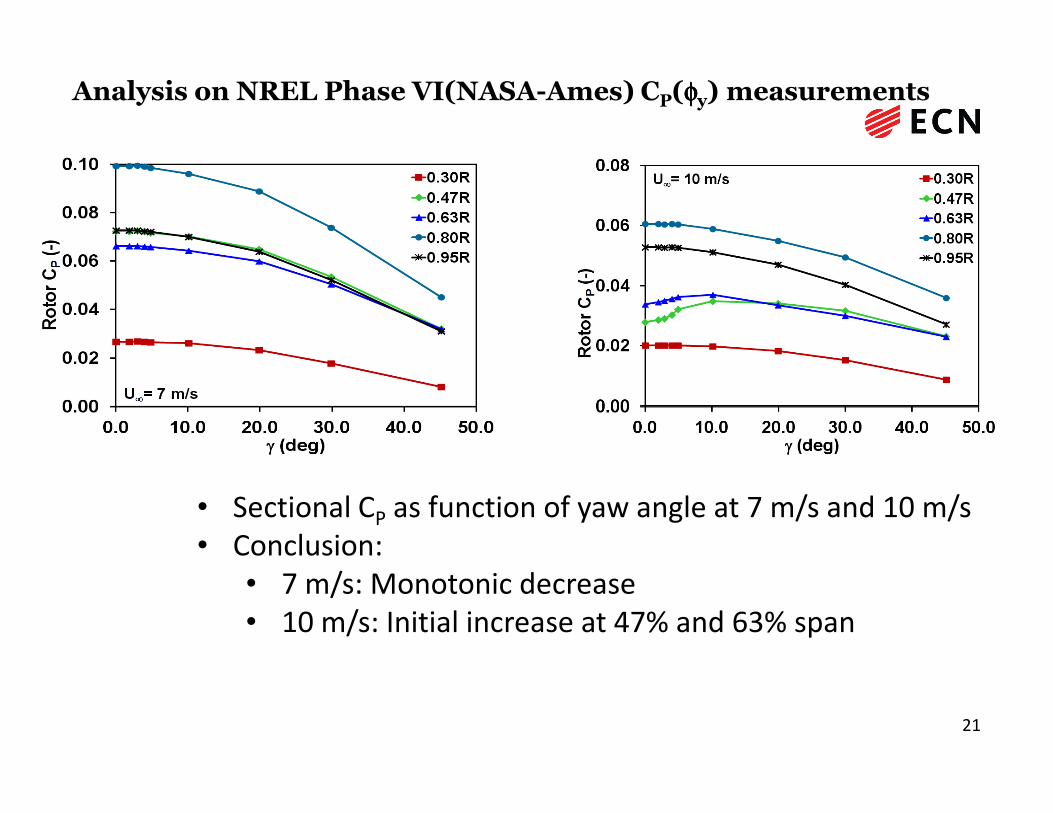
Analysis on NREL Phase VI(NASA-Ames) CP(φφφφy) measurements
21
• Sectional CP as function of yaw angle at 7 m/s and 10 m/s• Conclusion:
• 7 m/s: Monotonic decrease• 10 m/s: Initial increase at 47% and 63% span

Analysis on NREL Phase VI(NASA-Ames) measurements at yaw
22
Sectional torque coefficient as function of azimuth angle at different yaw angles
Conclusion:• Strong unsteady aerodynamic effects dependant on yaw angle• Non-linear unsteady aerodynamic effects determine the rotor averaged torque
(i.e. power)
Value of aerodynamic wind tunnel measurements because:
• The P(φy) behaviour could be deteremined at well defined conditions
• The sectional P(φy) behaviour could be determined
• The unsteady airfoil aerodynamics could be determined at yaw
• The conclusion can be drawns that high wind speeds, low pitch angles, and the
233-2-2013
inner part of the blad makes a a power increases with yaw angle more likely
� large angles of attack lead to a power increases due to unsteady airfoil
aerodynamics
• Remaining question: Why does BEM overpredicts the power at yawed conditions
• Possibly related to the generally accepted calculation of disc averaged
induction according to Glauert:
Fax = ρ Ar | Vw + ui0| . 2 ui0

Content
• Importance of wind turbine aerodynamics
– Aerodynamic design modelling
– Aerodynamic measurements
• Aerodynamic wind turbine measurements
– IEA projects on field and wind tunnel measurements– IEA projects on field and wind tunnel measurements(IEA Task 14, IEA Task 18, IEA Task 20 and IEA Task 29 (Mexnext-I))
• Power at yawed conditions in NASA-Ames measurements
– Current and future developments
24

Validation measurements, status at ~2005
1990:
Measurements of power and loads showed differences but they were too global to form a basis for improvement of aerodynamic modelsmodels
Desired:
• Local aerodynamic loads (pressure distribution) in field conditions (IEA Tasks 14/18)
• Constant, uniform and controlled conditions (�NASA-Ames windtunnel measurements from IEA Task 20 )
• But also: Induced velocities and wake velocities (� Detailed flow field measurements from Mexico project) 25
3-2-2013

• Coordinated by ECN
• 2001-2006
• Measurements in German
Dutch Wind tunnel, DNW
– North East Polder
(Netherlands)
– Open test section:
Rotor aerodynamic measurements: EU project Mexico
Model rotor EXperiments In COntrolled conditions 1)
263-2-2013
9.5 x 9.5 m2
– Diameter of rotor:4.5 m
– Fast pressure measurements at 5 positions
(25%, 35%, 60%, 82% and 92% span) along
the blade
– Particle Image Velocimetry (PIV):
Quantitative flow visualisation
1) Participants: see http://www.ecn.nl/nl/units/wind/rd-programma/aerodynamica/projects/mexico/

Rotor aerodynamic measurements:
IEA Task 29 MexNext-I: Goals and Participants
– Goal: Analysis of Mexico measurements
– Participation from the following institutes from 11 different countries:
– Canada (École de technologie supérieur, Montreal (ETS), University of Victoria (UVic))
– Denmark(DTU-RISO/DTU(Mek))
– Germany(University of Stuttgart (IAG), University of Applied Sciences, Kiel, Forwind)
– Israel (Israel Institute of Technology (Technion))– Israel (Israel Institute of Technology (Technion))
– Japan (Mie University/National Institute of Advanced Industrial Science)
– Korea((Korea Institute of Energy Research (Kier) and Korea Aerospace Research Institute (Kari))
– Netherlands(Energy Research Center of the Netherlands (ECN), University of Delft (TUDelft), Technical University of Twente, Suzlon Blade Technology)
– Norway (Institute for Energy Technology/Norwegian University of Science and Technology (IFE/NTNU) )
– Spain(Renewable Energy National Centre of Spain (CENER) and National Institute for Aerospace Technology, INTA)
– Sweden(Royal Institute of Technology/University of Gotland (KTH/HGO))
– USA (National Renewable Energy Laboratory (NREL)) 273-2-2013
Results from Mexnext-I
• Has already been presented where it is mainly the combination of flow field measurements and detailed aerodynamic measurements on the blade which made the Mexico experiment unique
283-2-2013

Content
• Importance of wind turbine aerodynamics
– Aerodynamic design modelling
– Aerodynamic measurements
• Aerodynamic wind turbine measurements• Aerodynamic wind turbine measurements
– IEA projects on field and wind tunnel measurements(IEA Task 14, IEA Task 18, IEA Task 20 and IEA Task 29 (Mexnext-I))
• Power at yawed conditions in NASA-Amesmeasurements
– Current and future developments29

Current and planned developments on the
field of aerodynamic measurements
• IEA Task 29, Mexnext-II:
– Unexplored aerodynamic data from several facilities (both wind tunnel and field) to be
discussed at
– New Mexico measurements in DNW wind tunnel 1) based on the existing measurement
set-up to complement the databaseset-up to complement the database
• UAE Phase VII: New measurements in NASA-Ames wind tunnel
• TUDelft wind tunnel measurements
• Mie wind tunnel measurements ----- and some more wind tunnel
measurements
• Dan-Aero: Danish field aerodynamic measurements
• EERA (European Energy Research Alliance) : New field facility
303-2-2013
1)Acknowledgment to ESWIRP and Inwind

DU Windtunnels for aerodynamic research
on wind turbines (Courtesy Gerard van Bussel)
LSTL tunnel
Vmax =110 m/s
test section 1.2 x 1.85 m
mainly for airfoil development
Open Jet Facility (2009)
Vmax =35 m/s
test section 3.0 m O 13 m long
rotor- and unsteady flow analysis
Open Jet tunnel
Vmax =15 m/s
test section 2.2 m O
mainly for rotor flow analysis

Mie University Wind Tunnel
Single return wind tunnel with open test sectionOutlet diameter 3.6m
or 3.0m using high contraction nozzleSuction section 4.5m x 4.5m rectangular cross-section Length of test section 4.5mWind speed 0 - 30m/s for 3.6m nozzleUniformity < 1.5% (7m/s)Turbulence level < 0.5% (7m/s)Measurements e.g. pressure measurements along blade, LDA

Rotor with diameter of 3.4 meter

EERA Field experiment, background
– Wind tunnel measurements and field measurements should be seen as COMPLEMENTARY– Wind tunnel measurements are done at well known (but less
representative) conditions
– This facilitates the interpretation of data and enables the determination
of e.g. the P(φy) behaviour
– Field measurements are done at representative (but less known) conditions
343-2-2013
– Field measurements are done at representative (but less known) conditions
– We see initiatives on wind tunnel measurements (e.g. New
Mexico/NASA-Ames/TUDelft) but not on field measurements:– The time is ripe for a PUBLIC aerodynamic field experiment on a wind
turbine representative for the current and future generation of wind
turbines based on:
– Most innovative measurement techniques – Carried out under auspices of EERA (European Energy Research
Alliance)

Conclusions
• Since the end of the 80’s/beginning of the 90’s dedicated
aerodynamic measurements have been performed on wind
turbines both in the field and the wind tunnel.
• The level of maturity of these measurements has been improved
enormously over the years.
• The measurements have delivered a huge amount of data and
knowledge by which design codes could be improved and
validated which led to more reliable and efficient wind turbine
designs.
353-2-2013

Questions?
363-2-2013

ECN-M--13- Fout! Geen tekst met de opgegeven stijl in he
ECN Westerduinweg 3 P.O. Box 1 1755 LE Petten 1755 LE Petten The Netherlands The Netherlands T +31 88 515 4949 F +31 88 515 8338 info@ ecn.nl www.ecn.nl
![SinGAPORE AIRLInES A380* 456 ! A380] 333 A380 E 1531 …singapore airlines a380* 456 ! a380] 333 a380 e 1531 a330 [1-2-1 singapore airlines](https://img.dokumen.tips/doc/110x75/5f1f304da44bc1238e46c157/singapore-airlines-a380-456-a380-333-a380-e-1531-singapore-airlines-a380-456.jpg)


![Effects of Reynolds Number and Flapping Kinematics on Hovering Aerodynamics · aerodynamics and fluid physics as suggested in [5]. Despite the importance of 3-D effects, comparison](https://img.dokumen.tips/doc/110x75/5fd315a4fb472c1f815b8916/effects-of-reynolds-number-and-flapping-kinematics-on-hovering-aerodynamics-aerodynamics.jpg)


