Embed Size (px)
Citation preview

THE IMPLANT OF TOMORROWSPECIAL PROPERTIES – UNIQUE BENEFITS: MAGNEZIX®
Intelligent innovations for a better life.www.syntellix.com

Top-Innovator2016
Metallic and biotransformable.Osteoconductive.Reduced risk of infection.
No remaining foreign material.
Practically no radiological artefacts.Suitable for diagnostics in MRI and CT.
Free of aluminium, nickel, chromium and cobalt.Excellent biocompability, no known allergies.Reduced risk of stress shielding.
Similar stability tocomparable titanium implants.
Up to 5 times higher stabilitythan polymer pins.
STABILITY, RESORBABILITY AND OSTEOCONDUCTIVITY DEFINE A NEW STANDARD OF IMPLANTS!
THE GAME CHANGER AND INNOVATION LEADER: MAGNEZIX®
Worldwide innovation leader Most implants in the field of orthopedic surgery are made of non-resorbable mate-
rials such as steel or titanium which permanently remain in the body or have to be
removed in a second surgery. These permanent implants can cause stress shielding,
provoke inflammatory or foreign body reactions. In order to minimize these prob-
lems, resorbable, yet stable implants have become subject of extensive research.
While there were many approaches to design a material that provides both adequate
mechanical and degradation properties combined with excellent biocompatibility,
MAGNEZIX® hit the market as the globally first biotransformable metallic implant
material approved for human use.
Inventing new technologies There were good reasons to think about using magnesium in orthopedic surgery:
1. An implant consisting of a magnesium based alloy would initially be
as strong as a traditional bone implant made of steel or titanium and
would, additionally, gradually dissolve.
2. It would show very good biocompatibility, strong osteogenic potential
and infect inhibiting effects.
The challenge was to develop the right magnesium-based alloy suitable for
osteosynthesis. The MAGNEZIX® alloy is based on the MgYREZr system and shows
excellent values of strength properties (yield strength > 260 MPa, tensile strength
> 290 MPa) and is free of known allergenic elements. Additionally, adapted casting,
powdermetallurgical and extrusion processes significantly enhance the unique
properties of the final product.
Progress requires change
The implementation of this innovation has not only led to a vast range of
new possibilities, but also had and still has to deal with prejudices and
reservation. In the end, every innovation requires reconsideration
and every state-of-the-art product once was new and uncommon!
CE approval for MAGNEZIX®
compression screws (CS) was
granted in 2013, for the first
time enabling the clinical use
of a degradable bio-metal in
Europe. In 2015 and 2016,
new screw sizes and the
MAGNEZIX® Pin broadened
the CE-approved portfolio.
MAGNEZIX®

In relation to 25,000 units sold worldwide (631 received
feedbacks), there were just 27 genuine clinical undesirable
effects announced to us, of which only 4 had to be reported
to the health authorities (BfArM/BASG). Further analysis
and examinations proved that not a single reported case
could be attributed to the implant itself.
IN THOUSANDS OF SURGERIES NOT A SINGLE UNWANTED RESULT WAS ATTRIBUTED TO THE PRODUCT!*
Sour
ce: O
ffic
ial v
igila
nce
data
Syn
telli
x A
G, D
ecem
ber
20
16
0.11 % – this very low rate of announced events shows that MAGNEZIX® implants are safe and that there is no inadequate risk for the clinical use of the implant in patients.
0 CASES ATTRIBUTED TO THE PRODUCT!
4REPORTED
CASES
27UNDESIRED
EFFECTS
25,000IMPLANTS
631 FEEDBACKS ON
IMPLANTS
*All mentioned events seem to have been caused by the applicants' learning curve for the proper useand normal clinical course of the implant. Not a single case could be attributed to the product itself orits material.Under no circumstances the product can be regarded more risky than comparable products which are already in wide spread use worldwide.
MAGNEZIX® IS AN INNOVATION WITH PROVEN BENEFITS!Being a natural material, magnesium is subject to a biological degradation process!When using magnesium implants for the first time, surgeons are not used to some degradation-related
appearances they see in conventional X-rays. First, on postoperative radiographs, a MAGNEZIX® im-
plant is not as dense as a titanium or steel implant. Second, during radiological control, the phenome-
non of radiolucency may temporarily occur around the implant. This is a general phenomenon of the
degradation processes of magnesium and therefor also associated with MAGNEZIX®: While the material
dissolves, there is a naturally loss of mass and weight. Also, magnesium releases small quantities of
hydrogen gas which will be resorbed over time. Due to the osteoconductive capacity of MAGNEZIX®,
osteoclasts and osteoblasts will appear, helping to enable the process of bone remodeling, and osteoid
(non-mineralized bone matrix) is formed.
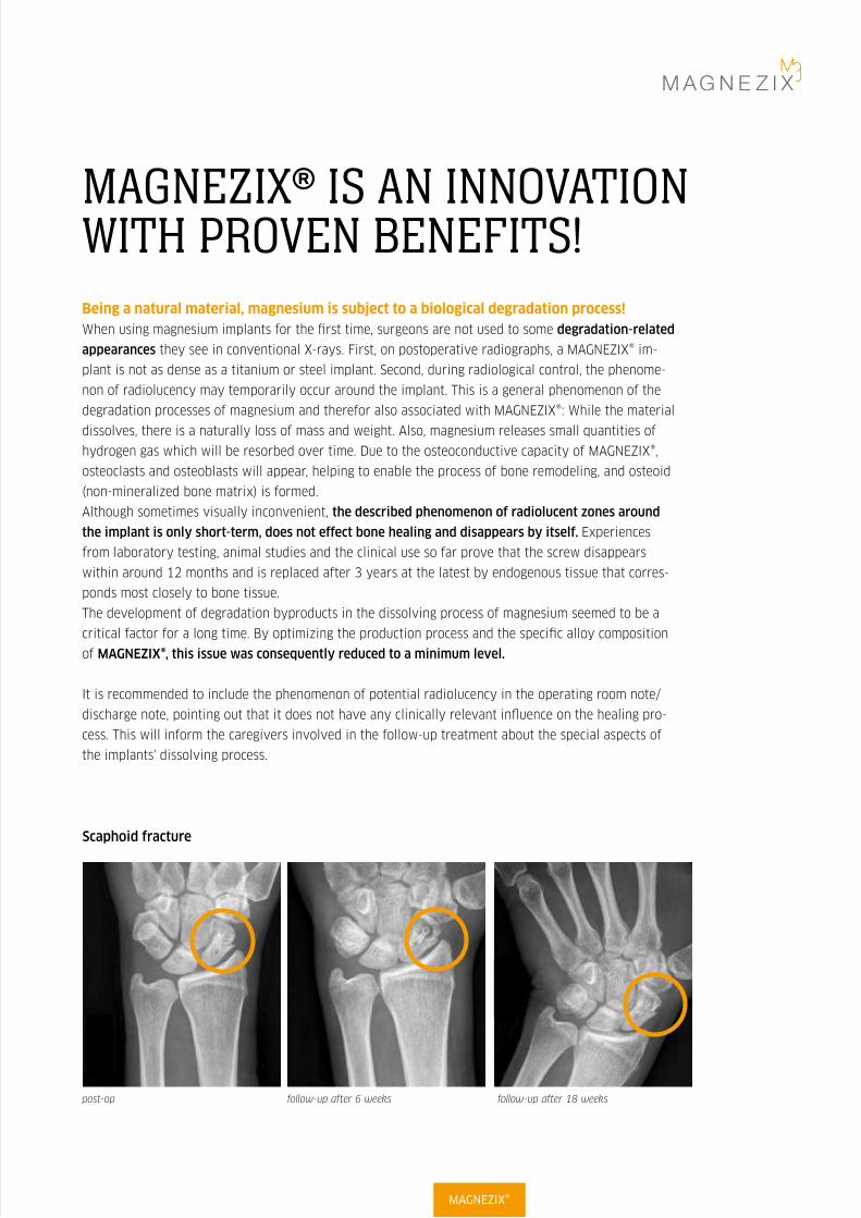
Although sometimes visually inconvenient, the described phenomenon of radiolucent zones around
the implant is only short-term, does not effect bone healing and disappears by itself. Experiences
from laboratory testing, animal studies and the clinical use so far prove that the screw disappears
within around 12 months and is replaced after 3 years at the latest by endogenous tissue that corres-
ponds most closely to bone tissue.
The development of degradation byproducts in the dissolving process of magnesium seemed to be a
critical factor for a long time. By optimizing the production process and the specific alloy composition
of MAGNEZIX®, this issue was consequently reduced to a minimum level.
It is recommended to include the phenomenon of potential radiolucency in the operating room note/
discharge note, pointing out that it does not have any clinically relevant influence on the healing pro-
cess. This will inform the caregivers involved in the follow-up treatment about the special aspects of
the implants' dissolving process.
post-op follow-up after 6 weeks follow-up after 18 weeks
Scaphoid fracture
MAGNEZIX®
MAGNEZIX® implants provide an ideal stability since their mechanical properties are very close to those of cortical bone!MAGNEZIX® implants were designed to gain a primary stability as in implants
made of steel or titan and a load capacity which is 5 times higher compared to
polymerbased pins.
During the healing process, these magnesium implants naturally loose their origi-
nal shape. In some cases they even appear as if they were broken, seen in image
based diagnostic procedures. This phenomenon does not result from a lack of
primary stability but is due to the fact that they are degrading as intended while
the healing bone optains the ability to bear higher load capacitys (see X-rays on
the left side).
It should be noted that MAGNEZIX® CS implants follow a magnesium-specific
design which cannot be directly compared to titanium screws one to one (e.g. in
terms of diameters). Thus, compared to titanium screws, it is recommended to
use the next bigger MAGNEZIX® screw diameter in most cases.
The fact of using a self-cutting yet not a self-drilling screw should be considered
as well. In some rare cases, the head of the screw had broken due to inadequate
skipping of pre-drilling of either the cancellous or the cortical bone or both. For
screws with self-tapping tips, pre-drilling over the desired screw length is man-
datory, facilitating the subsequent tightening of the screw and reducing the rota-
tion of small bone fragments.
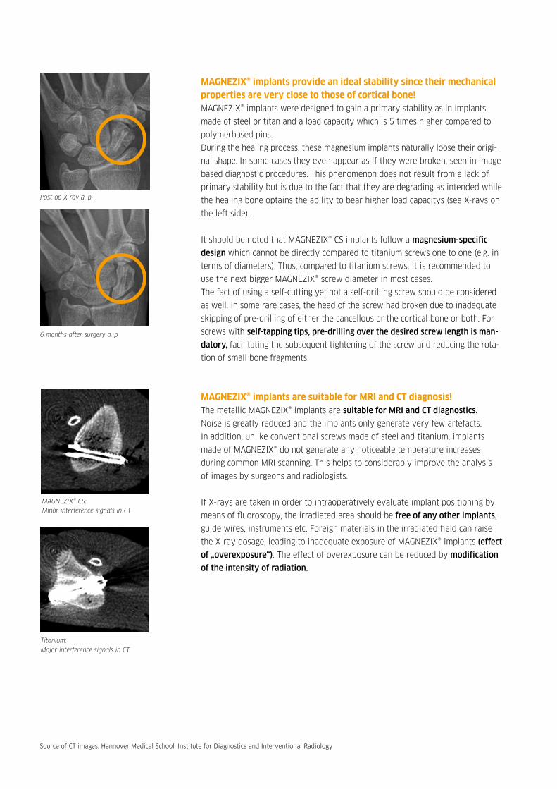
MAGNEZIX® implants are suitable for MRI and CT diagnosis!The metallic MAGNEZIX® implants are suitable for MRI and CT diagnostics.
Noise is greatly reduced and the implants only generate very few artefacts.
In addition, unlike conventional screws made of steel and titanium, implants
made of MAGNEZIX® do not generate any noticeable temperature increases
during common MRI scanning. This helps to considerably improve the analysis
of images by surgeons and radiologists.
If X-rays are taken in order to intraoperatively evaluate implant positioning by
means of fluoroscopy, the irradiated area should be free of any other implants,
guide wires, instruments etc. Foreign materials in the irradiated field can raise
the X-ray dosage, leading to inadequate exposure of MAGNEZIX® implants (effect
of „overexposure“). The effect of overexposure can be reduced by modification
of the intensity of radiation.
Post-op X-ray a. p.
6 months after surgery a. p.
MAGNEZIX® CS: Minor interference signals in CT
Titanium: Major interference signals in CT
Source of CT images: Hannover Medical School, Institute for Diagnostics and Interventional Radiology

Degrading magnesium has osteogenic properties and reduces the risk of infections!Magnesium is a biologically active material and can support the healing process. Both, in vitro and
in vivo studies have shown excellent cell compatibility and distinct osteoconductive properties of
magnesium alloys. In vitro trials with MAGNEZIX® have demonstrated a high proliferation rate of
human osteoblasts and a stimulation of vitality.
Magnesium degrades via a corrosion process that creates a basic environment close to the implant,
inhibiting bacterial growth. Furthermore, the presence of released hydrogen (or hydrogen ions) is
described to be particularly advantageous in the human organism regarding cell and tissue protection.
Hydrogen, in this context, acts as an antioxidant which selectively binds and defuses DNA-changing
hydroxyl radicals or peroxi nitrides. These positive effects, proven for pure magnesium, can be strongly
anticipated for MAGNEZIX®. Additionally, in order to minimize the risk of infection, all MAGNEZIX®
implants are individually sterile packaged.
MAGNEZIX® implants are free of nickel and aluminum and do not provoke any known allergies!Magnesium itself has a very good and proven biocompatibility, which – amongst others – results
from the high daily need of humans for the element magnesium. Within bone, it is easily available
for resorption. This way, a magnesium implant that degrades within the bone can become a source
of essential magnesium ions.
Since magnesium is a natural material essential for the body, generally it is very unlikely to provoke
allergies. One advantage of MAGNEZIX® in this context is that it consists of more than 90 % magnesium.
It contains no nickel, cobalt, chromium or aluminium elements, which are all under suspicion to cause
severe diseases. In summary, there are absolutely no allergies or foreign body reactions known for
MAGNEZIX® implants!
Supporting the healing process1
1 Source: Waizy H, Diekmann J, Weizbauer A et al. (2014). In vivo study of a biodegradable orthopedic screw (MgYREZr-alloy) in a rabbit model for up to 12 months. J Biomater Appl 28 (5), 667-75.
MAGNEZIX®
Image of histological examination show outline of implanted screw (from above) after surgery.
After 12 months the screw has fully degraded: it has been replaced by a potassium compound (1) with ingrowth of new bone (2).
After three months you can see that the screw is partially degraded (in circle).
2
1

MAGNEZIX® MEETS ALL CRITERIA OF AN IDEAL IMPLANT!
TITANIUM STEEL POLYMERS MAGNEZIX©
Degradation No No 1-6 years, beginning
immediately
1-2 years, beginning
immediately
Loss of stability half-
value period
Only fatigue Only fatigue 10-50 % after
12 weeks
App. 50 % after 12 weeks
Young`s modulus
(bone: 12-25 GPa)
105 GPa
(5 times higher)
193 GPa
(10 times higher)
4 GPa (lower) 47 GPa
(2 times higher - ideal)
Tensile strength
(bone: 150 MPa)
539 MPa 275-520 MPa 10-150 MPa > 290 MPa
Biocompatibility Gold standard Foreign body
reactions known
Foreign body
reactions known
Good, proven with
ISO 10993-1
Degradation products No resorption No resorption Not finally checked Biocompatible and bio-
absorbable oxides and
hydroxides, hydrogen gas
Radiology
(CT, X-ray, MRI)
Good visible,
partially with
artefacts
Good visible,
extensive arte-
facts
No artefacts, partially
not visible
Low artefacts, visible
with X-ray
MAGNEZIX® has mechanical stability values which are far above the values of those bioresorbable materials previously
available. The mechanical properties of the MAGNEZIX® alloy, determined after the final extrusion process, result in yield
strength properties higher than 260 MPa, tensile strength properties higher than 290 MPa and elongation to failure prop-
erties higher than 8 %. With a Young’s Modulus of 47 GPa, the biomechanical properties of MAGNEZIX® are very close to
those of human bone. The good bone-like stress-strain ratio effectively counteracts stress shielding effects that can result
in loss of bone density (osteopenia). Consequently, the significant higher elasticity compared to steel or titanium implants
implies micro-movement in the fracture zone leading to better healing conditions.

- Fingers
VARIOUS APPLICATIONS – ONE SIMILARITY: NO REMAINING OF FOREIGN MATERIAL!
Intelligent innovations for a better life.www.syntellix.com
Clinical application: distale fibula fracture
44 June, 2016
pre op 19.12.13 follow up 30.08.14follow up 17.03.14follow up 30.01.14post op 20.12.13
- Calcaneus
- Distal humerus
- Radial head
- Outer malleolus
- Scaphoid
- Trochanter
- Distal phalanx
MAGNEZIX®

THIS SCREW TURNS INTO BONEMAGNEZIX® CS
Intended UseMAGNEZIX® CS biotransformable compression screws serve the purpose of re-establishing bone con-
tinuity after fractures and osteotomies (osteosynthesis) as well as for treatment of pseudarthroses
(re-osteotomies). The objective when using the MAGNEZIX® CS device is specifically anatomic retention
by way of surgical splinting of assembled bone fractions after prior repositioning until bony healing.
The implants are designed for single use only.
IndicationsThe indications for MAGNEZIX® CS implants are reconstructive procedures after fractures, malposi-
tions and/or other pathological bone alterations of the human skeleton. The surgeon must in all cases
determine the extent of the injuries or the bony alterations and the scope of the necessary surgical
intervention and select the appropriate operating procedure and the appropriate implant. This applies
in particular when using biotransformable MAGNEZIX® implants. The surgeon is always responsible for
the decision to use the implant.
According to its respective dimension, MAGNEZIX® CS can be used for adaption- and exercise-stable
fixation of bones and bone fragments in children, adolescents and adult persons. Relevant medical
literature and guidelines must be observed when determining the dimensions of screws to be used.
The MAGNEZIX® CS is for example suitable for the following:
Î Intra-articular and extra-articular fractures of small to medium-sized bones and bony fragments
Î Arthrodeses, osteotomias and pseudarthroses of small to medium-sized bones and small joints
Î Small bony avulsions of ligaments and tendons
Among others:
Î Distal tibia
Î Calcaneus, talus and
metatarsus
Re-fixation of bony
fragments for example:
Î Proximal humerus
Î Distal femur
Î Proximal tibia
Including:
Î Phalanges, metacarpalia
Î Processus styloideus radii et ulnae
Î Capitulum and caput radii
Î Osteochondrosis dissecans
Î Carpalia, metacarpalia, tarsalia
and metatarsalia
Î Epicondylus humeri
Î Hallux-valgus-corrections
Absolute contraindications
Î Insufficient bone substance to anchor the implant Î
Evidence or suspicion of septic-infectious operating area
Î Known allergies and/or known foreign body reactions
Î Application in the area of the epiphyseal plates
Î Load-stable osteosyntheses
Î Arthrodeses of medium-sized and large joints
Î Use in the spinal column
Relative contraindications
Î Options for conservative treatment
Î Acute sepsis
Î Osteoporosis
Î Alcohol and/or drug misuse
Î Epilepsy
Î Limited skin/soft tissue conditions
Î Non co-operative patient or limited mental
state of patient
Î No possibility for providing adequate post-
operative follow-up (e.g. temporary load relief)
CONTRAINDICATIONS
In specific clinical situations the use of MAGNEZIX® implants may be prohibited (absolute contraindication) or use
may be planned subject to certain considerations (relative contrain-dication).
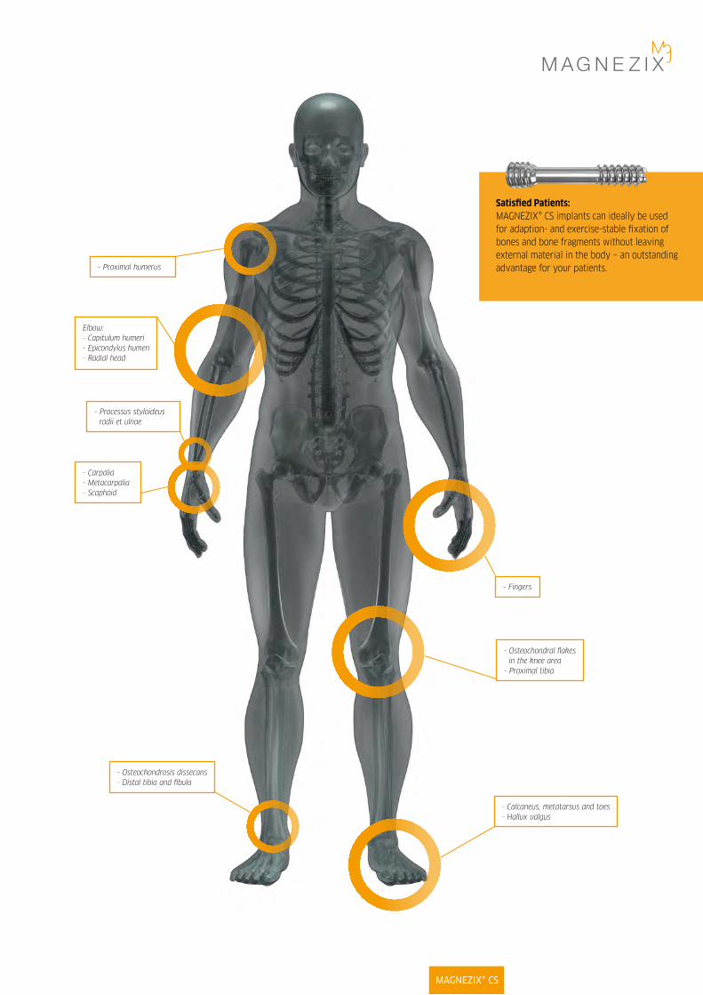
Satisfied Patients: MAGNEZIX® CS implants can ideally be used for adaption- and exercise-stable fixation of bones and bone fragments without leaving external material in the body – an outstanding advantage for your patients.
MAGNEZIX® CS
- Calcaneus, metatarsus and toes- Hallux valgus
- Fingers
- Osteochondral flakes in the knee area
- Proximal tibia
- Processus styloideus radii et ulnae
- Carpalia- Metacarpalia- Scaphoid
- Osteochondrosis dissecans- Distal tibia and fibula
Elbow:- Capitulum humeri - Epicondylus humeri- Radial head
- Proximal humerus

SG
MAGNEZIX® CS PRODUCT OVERVIEW
MAGNEZIX® CS 2.0 MAGNEZIX® CS 2.7 MAGNEZIX® CS 3.2
3.5 mm
L
Ø 4.0 mm head thread
Ø 2.4 mm shaft diameter
Ø 3.2 mm shaft thread
3.5 mm
L
Ø 3.6 mm head thread
Ø 2.1 mm shaft diameter
Ø 2.7 mm shaft thread
3.0 mm
L
Ø 2.5 mm head thread
Ø 1.6 mm shaft diameter
Ø 2.0 mm shaft thread
DIMENSIONS
Art. No. Threaded Screw
shaft length length
[mm] SG [mm] L_____________________________________________
1020.008 4 8
1020.010 4 10
1020.012 4 12
1020.014 5 14
1020.016 5 16
1020.018 5 18
1020.020 6 20
1020.022 6 22
1020.024 6 24
Art. No. Threaded Screw
shaft length length
[mm] SG [mm] L_____________________________________________
1032.010 4 10
1032.012 5 12
1032.014 5 14
1032.016 7 16
1032.018 7 18
1032.020 7 20
1032.022 7 22
1032.024 7 24
1032.026 7 26
1032.028 7 28
1032.030 7 30
1032.032 9 32
1032.034 9 34
1032.036 9 36
1032.038 9 38
1032.040 9 40
Art. No. Threaded Screw
shaft length length
[mm] SG [mm] L_____________________________________________
1027.010 4 10
1027.012 5 12
1027.014 5 14
1027.016 7 16
1027.018 7 18
1027.020 7 20
1027.022 7 22
1027.024 7 24
1027.026 7 26
1027.028 7 28
1027.030 7 30
1027.032 9 32
1027.034 9 34
SGSG

Biotransformable magnesium alloyThe use of MAGNEZIX® makes subsequent removal
of the implant obsolete: furthermore MAGNEZIX®
promotes the bone healing process. MAGNEZIX® is
biotransformable, biocompatible and non-toxic in
a biological environment.
The use of the innovative MAGNEZIX® metal alloy
allows the screw to be implanted using standard
techniques.
Self-tapping screw tipThe self-tapping properties of the screw tip
reduce the operation time and simplify the
surgical application technique.
Cannulated screwThe screw is cannulated (hollow) to allow controlled
positioning of the screw using the guide wire.
This feature supports minimal invasive surgery.
Self-tapping head threadThe self-tapping design of the screw head simplifies
insertion and countersinking of the screw head.
Different thread pitchesThe threads of the head and the shaft have
different thread pitches. This adapted design of the
screw generates compressive forces and supports
the intended inter-fragmentary compression.
Self-holding screwdriverThe head of the screw is of T4/T7/T8
(ISO 10664-4/7/8) design. The advantages
of this ISO standardized technology are:
Î Enlarged contact area
Î Improved self-retaining mechanism
Î Improved torque transmission
ADVANTAGESAND FEATURESMAGNEZIX® CS IMPLANTS
MAGNEZIX® CS
Warnings
In the case of concurrent use of third party implants it must borne in mind that steel, titanium and cobalt-chromium alloys may not remain in
direct contact with a MAGNEZIX® implant at the intervention site (i.e. no physical contact of implants). Since the implants are designed for
single use only, reuse of MAGNEZIX® implant devices is grossly negligent and can result in an increased risk of infection and loss in implant
stability. In general, re-sterilization alters the implant’s functionality in an unpredictable way.

SURGICAL TECHNIQUEMAGNEZIX® CS 2.0 – STEP BY STEP
Prior to implanting a MAGNEZIX® CS 2.0 screw it is necessary to ensure repositioning and temporary stabiliza-
tion of the fracture or the osteotomy.Although the MAGNEZIX® CS 2.0 screw has a self-cutting tip, a pilot hole
must always be predrilled. The pilot hole also allows precise selection of the correct screw length.
Step 1: Drilling the pilot holePosition the double drill guide through the soft tissue to
the bone. Insert the drill bit through the double drill guide
and into the bone, possibly monitoring with the image in-
tensifier until it is at the required depth.
Important: If no pilot hole is drilled, the precise screw
length cannot be correctly determined. Pre-drilling with an
incorrect alignment can lead to malfunction of the screw.
Step 2: Determination of screw lengthThe length of the screw is determined by means of the
depth gauge to determine the depth of the pre-drilled pilot
hole in the bone. (18 mm in the figure).
Important: When selecting the length of the screw one has
to ensure proper compression of the fracture gap.
Step 3: CountersinkingIn order to simplify insertion of the screw head the
head-side of the intended implant position is now reamed
using the countersink.
Important: If the screw is positioned perpendicular to the
bone surface, countersinking to the first ring marking (RM
1) is required in order to achieve adequate countersinking
of the screw head. If the screw is positioned at an angle of
45° to the bone surface, countersinking to the second ring
marking (RM 2) is required in order to achieve adequate
countersinking of the screw head.
Step 4: Inserting the screwThe MAGNEZIX® Compression Screw 2.0 of the previously
determined length (step 2) is now screwed into place.
Important: Bear in mind that the shaft thread could pull
out of the distal bone fragment if the induced compression
forces when screwing-in the screw are excessive. If the
selected screw is too short the shaft thread might cross the
fracture or osteotomy gap. If this situation results no com-
pression will be generated. Therefore, to ensure the correct
position of the threaded shaft it is recommended to check
the position using an image intensifier.
If one finds the thread crossing the fracture or osteotomy
gap the screw must be removed and a longer screw has to
be selected in order to generate compression. When doing
this and in the case of a hard (dense) bone situation, it
might be necessary to repeat the pre-drilling process as
described in step 1 to further deepen the pre-drilled pilot
hole for the selected screw with an adequate length.

STEP 3 STEP 4
STEP 1 STEP 2
RM 1
RM 2
0°
45°
Instruments used:➀ 9020.033 Double Drill Guide, Ø 2.2/1.5 mm➁ 9020.020 Drill Bit, Ø 1.5 mm
➀ 9020.033 Double Drill Guide, Ø 2.2/1.5 mm➁ 9020.021 Countersink Ø 2.2/1.5 mm, for quick coupling
➀ 6020.104 Screwdriver T4, One-Piece Handle | Optional:6020.204 Screwdriver T4, Multi-Part Handle
➂ 9020.042 Depth Gauge for screws
MAGNEZIX® CS

SURGICAL TECHNIQUE MAGNEZIX® CS 2.7 AND 3.2 – STEP BY STEP
Prior to implanting a MAGNEZIX® CS 2.7 or 3.2 screw it is necessary to ensure repositioning and temporary stabilization
of the fracture or the osteotomy.
Step 1: Positioning the guide wirePosition the guide wire through the double drill guide with
fitted drill guide, if necessary monitor using image intensifi-
cation, until it is in the required position.
Important: Avoid excess force when inserting the guide wire.
Excess force will bend the guide wire and may hinder subse-
quent reaming or insertion of the screw.
Step 2: Determination of screw lengthThe length of the screw is determined by sliding the mea-
suring device over the guide wire to the bone. The end of
the guide wire, visible in the scale of the measuring device,
indicates the length of the screw to be used (22 mm in the
figure).
Important: Only the original guide wires guarantee correct
measurement.
Step 3: Pre-drillingFor screws with self-tapping tips, pre-drilling over the desi-
red screw lengths is mandatory. At this point, the cannulated
drill bit is directed by the underlying guide wire. This faci-
litates the subsequent tightening of the screw and prevents
the rotation of small bone fragments.
The drill bit calibration allows the drill depth reached to be
read at the top end of the drill guide. The fine ring marks
indicate 2 mm steps, the dominant ring marks indicate 10
mm drill steps.
Important: It is crucial to only drill to the tip of the guide
wire. Slowly pull the drill bit out vertically from the double
drill guide while slowly turning in a forward direction so as
to leave the guide wire in position.
Step 4: CountersinkingIn order to simplify insertion of the screw head, the head side
of the intended implant position is now reamed using the
countersink with the guide wire still in place.
Important: If the screw is positioned perpendicular to the
bone surface, countersinking to the first ring marking (RM 1)
is required in order to achieve adequate countersinking of the
screw head. If the screw is positioned at an angle of 45° to the
bone surface, countersinking to the second ring marking (RM
2) is required in order to achieve adequate countersinking of
the screw head. The countersink is pulled vertically out of the
drill guide while still slowly turning in the forward direction
so as to leave the guide wire in position.
Step 5: Insertion of the screwThis is now followed by the tightening of the
MAGNEZIX® Compression Screw 2.7/3.2 over the underlying
guide wire in the length previously determined in step 2.
Important: Take care to ensure that the guide wire was not
damaged during steps 1 through 4. A damaged guide wire
may result in the MAGNEZIX® Compression Screw 2.7/3.2 to
not end up fully turned in. In this case the guide wire must be
removed before insertion of the screw.Bear in mind that the
shaft thread could pull out of the distal bone fragment if the
induced compression forces when screwing-in the screw are
excessive. If the selected screw is too short the shaft thread
might cross the fracture or osteotomy gap. If this situation
results no compression will be generated. Therefore, to ensure
the correct position of the threaded shaft it is recommended
to check the position using an image intensifier. If one finds
the thread crossing the fracture or osteotomy gap the screw
must be removed and a longer screw has to be selected in
order to generate compression. When doing this and in the
case of a hard (dense) bone situation, it might be necessary
to repeat the pre-drilling process as described in step 3 to
further deepen the pre-drilled pilot hole for the selected
screw with an adequate length. When the screw is in its final
position the guide wire is removed.

STEP 3 STEP 4
STEP 5
Instruments used for 2.7:➀ 9027.033 Double Drill Guide, Ø 3.1/2.2 mm➁ 9027.034 Drill Guide, Ø 2.2/1.1 mm➂ 9027.040 Guide Wire Ø 1.0 mm, with trocar tip, length 100 mm or➂ 9027.041 Guide Wire Ø 1.0 mm, with threaded tip, length 100 mm
Instruments used for 3.2:➀ 9032.033 Double Drill Guide, Ø 3.5/2.5 mm➁ 9032.034 Drill Guide, Ø 2.5/1.3 mm➂ 9032.040 Guide Wire Ø 1.2 mm, with trocar tip, length 150 mm or➂ 9032.041 Guide Wire Ø 1.2 mm, with threaded tip, length 150 mm
➀ 9027.033 Double Drill Guide, Ø 3.1/2.2 mm➁ 9027.020 Drill Bit Ø 2.2/1.1 mm, cannulated,
length 100/75 mm, for quick coupling
➀ 9032.033 Double Drill Guide, Ø 3.5/2.5 mm➁ 9032.020 Drill Bit Ø 2.5/1.3 mm, cannulated,
length 160/135 mm, for quick coupling
➀ 9027.033 Double Drill Guide, Ø 3.1/2.2 mm➂ 9027.021 Countersink Ø 3.1/1.1 mm, cannulated, for quick coupling
➀ 9032.033 Double Drill Guide, Ø 3.5/2.5 mm➂ 9032.021 Countersink Ø 3.5/1.3 mm, cannulated, for quick coupling
➀ 6027.107 Screwdriver T7, One-Piece Handle,Ø 1.1 mm cannulated | Optional:
6027.207 Screwdriver T7, Multi-Part Handle, Ø 1.1 mm cannulated
9027.033 Double Drill Guide, Ø 3.1/2.2 mm
➀ 6032.108 Screwdriver T8, One-Piece Handle,Ø 1.3 mm cannulated | Optional:
6032.208 Screwdriver T8, Multi-Part Handle, Ø 1.3 mm cannulated
9032.033 Double Drill Guide, Ø 3.5/2.5 mm
➃ 9027.042 Measuring Device for Guide Wires Ø 1.0 mm,Guide Wire length 100 mm
➃ 9032.042 Measuring Device for Guide Wires Ø 1.2 mm,Guide Wire length 150 mmm
STEP 1 STEP 2
Min. length10 mm
Max. length2.7: 34 mm 3.2: 40 mm
0 mm marker
RM 1
RM 2
RM 2
0° 45°
MAGNEZIX® CS

MAGNEZIX® CS 2.0
MAGNEZIX® CS 2.7 (similar to CS 3.2)
MAGNEZIX® CS 2.0, 2.7, 3.2OVERVIEW INSTRUMENTS AND TRAY
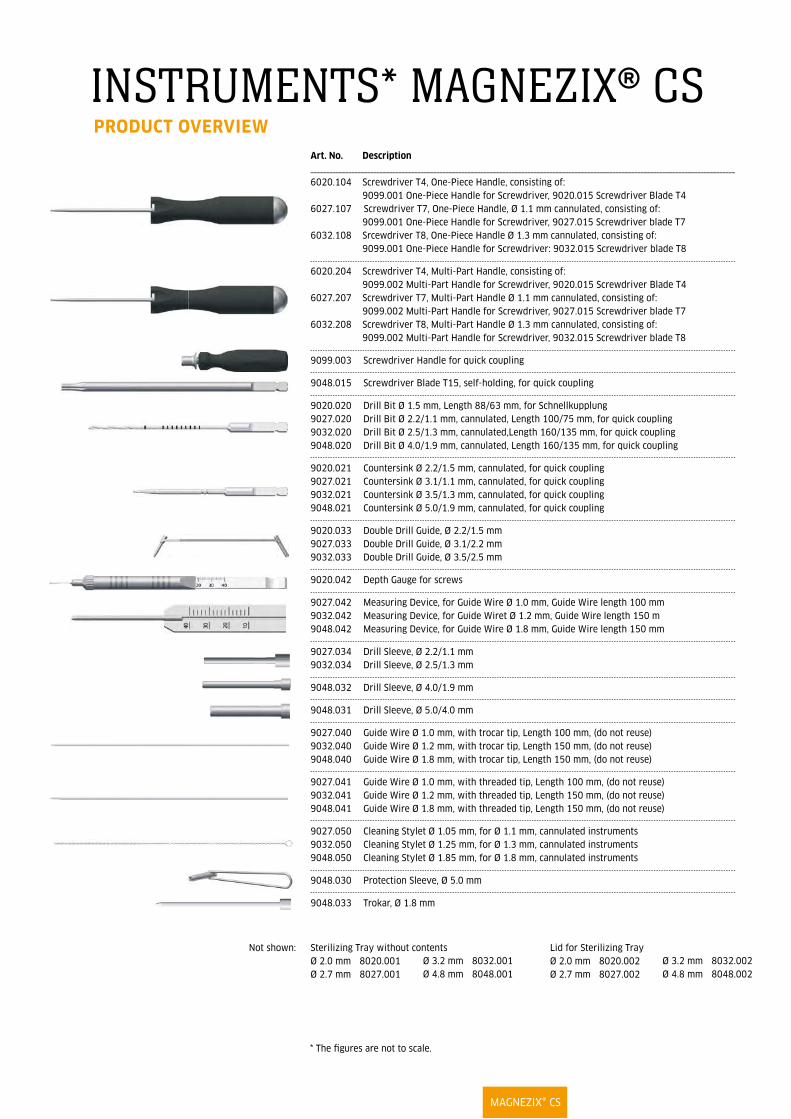
INSTRUMENTS* MAGNEZIX® CS PRODUCT OVERVIEW
* The figures are not to scale.
Art. No. Description_______________________________________________________________________________________________________________________________________
6020.104 Screwdriver T4, One-Piece Handle, consisting of: 9099.001 One-Piece Handle for Screwdriver, 9020.015 Screwdriver Blade T4
6027.107 Screwdriver T7, One-Piece Handle, Ø 1.1 mm cannulated, consisting of: 9099.001 One-Piece Handle for Screwdriver, 9027.015 Screwdriver blade T7
6032.108 Srcewdriver T8, One-Piece Handle Ø 1.3 mm cannulated, consisting of: 9099.001 One-Piece Handle for Screwdriver: 9032.015 Screwdriver blade T8
6020.204 Screwdriver T4, Multi-Part Handle, consisting of: 9099.002 Multi-Part Handle for Screwdriver, 9020.015 Screwdriver Blade T4
6027.207 Screwdriver T7, Multi-Part Handle Ø 1.1 mm cannulated, consisting of: 9099.002 Multi-Part Handle for Screwdriver, 9027.015 Screwdriver blade T7
6032.208 Screwdriver T8, Multi-Part Handle Ø 1.3 mm cannulated, consisting of: 9099.002 Multi-Part Handle for Screwdriver, 9032.015 Screwdriver blade T8
9099.003 Screwdriver Handle for quick coupling
9048.015 Screwdriver Blade T15, self-holding, for quick coupling
9020.020 Drill Bit Ø 1.5 mm, Length 88/63 mm, for Schnellkupplung9027.020 Drill Bit Ø 2.2/1.1 mm, cannulated, Length 100/75 mm, for quick coupling9032.020 Drill Bit Ø 2.5/1.3 mm, cannulated,Length 160/135 mm, for quick coupling9048.020 Drill Bit Ø 4.0/1.9 mm, cannulated, Length 160/135 mm, for quick coupling
9020.021 Countersink Ø 2.2/1.5 mm, cannulated, for quick coupling9027.021 Countersink Ø 3.1/1.1 mm, cannulated, for quick coupling9032.021 Countersink Ø 3.5/1.3 mm, cannulated, for quick coupling9048.021 Countersink Ø 5.0/1.9 mm, cannulated, for quick coupling
9020.033 Double Drill Guide, Ø 2.2/1.5 mm9027.033 Double Drill Guide, Ø 3.1/2.2 mm9032.033 Double Drill Guide, Ø 3.5/2.5 mm
9020.042 Depth Gauge for screws
9027.042 Measuring Device, for Guide Wire Ø 1.0 mm, Guide Wire length 100 mm9032.042 Measuring Device, for Guide Wiret Ø 1.2 mm, Guide Wire length 150 m9048.042 Measuring Device, for Guide Wire Ø 1.8 mm, Guide Wire length 150 mm
9027.034 Drill Sleeve, Ø 2.2/1.1 mm9032.034 Drill Sleeve, Ø 2.5/1.3 mm
9048.032 Drill Sleeve, Ø 4.0/1.9 mm
9048.031 Drill Sleeve, Ø 5.0/4.0 mm
9027.040 Guide Wire Ø 1.0 mm, with trocar tip, Length 100 mm, (do not reuse)9032.040 Guide Wire Ø 1.2 mm, with trocar tip, Length 150 mm, (do not reuse)9048.040 Guide Wire Ø 1.8 mm, with trocar tip, Length 150 mm, (do not reuse)
9027.041 Guide Wire Ø 1.0 mm, with threaded tip, Length 100 mm, (do not reuse)9032.041 Guide Wire Ø 1.2 mm, with threaded tip, Length 150 mm, (do not reuse)9048.041 Guide Wire Ø 1.8 mm, with threaded tip, Length 150 mm, (do not reuse)
9027.050 Cleaning Stylet Ø 1.05 mm, for Ø 1.1 mm, cannulated instruments9032.050 Cleaning Stylet Ø 1.25 mm, for Ø 1.3 mm, cannulated instruments9048.050 Cleaning Stylet Ø 1.85 mm, for Ø 1.8 mm, cannulated instruments
9048.030 Protection Sleeve, Ø 5.0 mm
9048.033 Trokar, Ø 1.8 mm
Sterilizing Tray without contentsØ 2.0 mm 8020.001Ø 2.7 mm 8027.001
Lid for Sterilizing TrayØ 2.0 mm 8020.002 Ø 2.7 mm 8027.002
Not shown:Ø 3.2 mm 8032.001Ø 4.8 mm 8048.001
Ø 3.2 mm 8032.002Ø 4.8 mm 8048.002
MAGNEZIX® CS
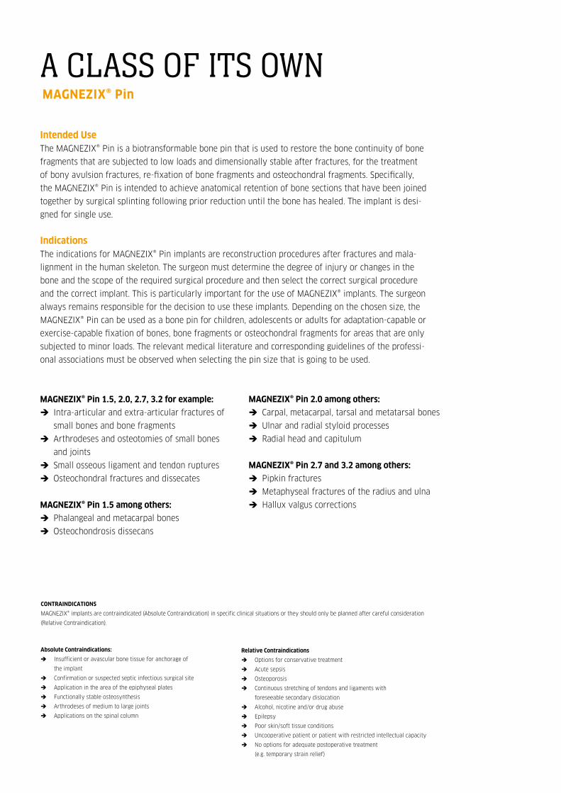
Intended UseThe MAGNEZIX® Pin is a biotransformable bone pin that is used to restore the bone continuity of bone
fragments that are subjected to low loads and dimensionally stable after fractures, for the treatment
of bony avulsion fractures, re-fixation of bone fragments and osteochondral fragments. Specifically,
the MAGNEZIX® Pin is intended to achieve anatomical retention of bone sections that have been joined
together by surgical splinting following prior reduction until the bone has healed. The implant is desi-
gned for single use.
Indications The indications for MAGNEZIX® Pin implants are reconstruction procedures after fractures and mala-
lignment in the human skeleton. The surgeon must determine the degree of injury or changes in the
bone and the scope of the required surgical procedure and then select the correct surgical procedure
and the correct implant. This is particularly important for the use of MAGNEZIX® implants. The surgeon
always remains responsible for the decision to use these implants. Depending on the chosen size, the
MAGNEZIX® Pin can be used as a bone pin for children, adolescents or adults for adaptation-capable or
exercise-capable fixation of bones, bone fragments or osteochondral fragments for areas that are only
subjected to minor loads. The relevant medical literature and corresponding guidelines of the professi-
onal associations must be observed when selecting the pin size that is going to be used.
MAGNEZIX® Pin 1.5, 2.0, 2.7, 3.2 for example:
Î Intra-articular and extra-articular fractures of
small bones and bone fragments
Î Arthrodeses and osteotomies of small bones
and joints
Î Small osseous ligament and tendon ruptures
Î Osteochondral fractures and dissecates
MAGNEZIX® Pin 1.5 among others:
Î Phalangeal and metacarpal bones
Î Osteochondrosis dissecans
Absolute Contraindications:
Î Insufficient or avascular bone tissue for anchorage of
the implant
Î Confirmation or suspected septic infectious surgical site
Î Application in the area of the epiphyseal plates
Î Functionally stable osteosynthesis
Î Arthrodeses of medium to large joints
Î Applications on the spinal column
MAGNEZIX® Pin 2.0 among others:
Î Carpal, metacarpal, tarsal and metatarsal bones
Î Ulnar and radial styloid processes
Î Radial head and capitulum
MAGNEZIX® Pin 2.7 and 3.2 among others:
Î Pipkin fractures
Î Metaphyseal fractures of the radius and ulna
Î Hallux valgus corrections
Relative Contraindications
Î Options for conservative treatment
Î Acute sepsis
Î Osteoporosis
Î Continuous stretching of tendons and ligaments with
foreseeable secondary dislocation
Î Alcohol, nicotine and/or drug abuse
Î Epilepsy
Î Poor skin/soft tissue conditions
Î Uncooperative patient or patient with restricted intellectual capacity
Î No options for adequate postoperative treatment
(e.g. temporary strain relief)
A CLASS OF ITS OWN MAGNEZIX® Pin
COMPRESSION SCREW 2.7MAGNEZIX® CS
CONTRAINDICATIONS
MAGNEZIX® implants are contraindicated (Absolute Contraindication) in specific clinical situations or they should only be planned after careful consideration
(Relative Contraindication).

MAGNEZIX® Pin
- Metaphyseal fracturesof the radius and ulna
- Tarsal and metatarsal corrections
- Fingers
Elbow:- Distal humerus- Radial head
- Osteochrondral flakes in the knee joint
- Metaphyseal fractures: distal femur / proximal tibia
- Distal radius and ulna
- Pipkin fractures
- Carpal andmetacarpal bones
- Proximal humerus
- Osteochondrosis dissecans
The outstanding stability (5x higher compared to PLA/PGA implants) of MAGNEZIX® Pins sets a whole new level for several indications in Traumatology and Sports surgery. Convince yourself!

MAGNEZIX® Pin 1.5 MAGNEZIX® Pin 2.0 MAGNEZIX® Pin 2.7 MAGNEZIX® Pin 3.2
Ø 5.0 mm head
Ø 3.2 mm shank
Ø 3.0 mm head
Ø 2.0 mm shank
Ø 2.5 mm head
Ø 1.5 mm shank
Ø 4.0 mm head
Ø 2.7 mm shank
Head height is 1.0 mm. Head height is 1.0 mm. Head height is 1.1 mm. Head height is 1.3 mm.
Art. No. Length [mm] ___________________________________
1115.008 8
1115.010 10
1115.012 12
1115.014 14
1115.016 16
1115.018 18
1115.020 20
1115.022 22
1115.024 24
1115.026 26
1115.028 28
1115.030 30
Art. No. Length [mm] ___________________________________
1120.008 8
1120.010 10
1120.012 12
1120.014 14
1120.016 16
1120.018 18
1120.020 20
1120.022 22
1120.024 24
1120.026 26
1120.028 28
1120.030 30
1120.032 32
1120.034 34
1120.036 36
1120.038 38
1120.040 40
Art. No. Length [mm] ___________________________________
1127.012 12
1127.014 14
1127.016 16
1127.018 18
1127.020 20
1127.022 22
1127.024 24
1127.026 26
1127.028 28
1127.030 30
1127.032 32
1127.034 34
1127.036 36
1127.038 38
1127.040 40
1127.042 42
1127.044 44
1127.046 46
1127.048 48
1127.050 50
Art. No. Length [mm] ___________________________________
1132.012 12
1132.014 14
1132.016 16
1132.018 18
1132.020 20
1132.022 22
1132.024 24
1132.026 26
1132.028 28
1132.030 30
1132.032 32
1132.034 34
1132.036 36
1132.038 38
1132.040 40
1132.042 42
1132.044 44
1132.046 46
1132.048 48
1132.050 50
MAGNEZIX® Pin PRODUCT OVERVIEW
DIMENSIONS

Hints
In isolated cases, temporary radiolucencies may be observed around the implant. It is recommended that the phenomenon of radiolucencies be
included in the operating room note / discharge note, pointing out that based on present knowledge the phenomenon does not have any rele-
vant influence on the process of healing. This will inform the caregivers involved in the follow-up treatment of the special aspects of the radio-
logical healing process. Since MAGNEZIX® implants are degraded completely in the body in the course of time and are replaced by endogenous
tissue, there is never any need to remove them.
Warnings
When using other makes of implant at the same time, it is important to note that steel, titanium and cobalt-chromium alloys in the surgical site
must not be in direct contact with a MAGNEZIX® implant for an extended period (physical contact between implants). Since the implants are
intended for single use only, re-use of MAGNEZIX® Pin implants constitutes gross negligence. It may lead to increased risk of infection and espe-
cially loss of implant stability. Re-sterilisation will have an incalculable impact on the product.
BIOTRANSFORMABLE MAGNESIUM ALLOY
Use of MAGNEZIX® implants makes any subsequent
implant removal unnecessary, and moreover, it sup-
ports the osseous healing process. MAGNEZIX® is
biotransformable, biocompatible and non-toxic wit-
hin a biological environment.
HEAD DESIGN
The flat designed head of the MAGNEZIX® Pin enab-
les stable reduction of the bone fragment. Prominent
protrusion of the implant involving possible damage
to proximal structures can thus be avoided and the
pin head can be completely countersunk.
In addition, a recess in the pin head improves positi-
oning of the impactor and the impactor is prevented
from slipping off the pin head during impaction.
AXIALLY STABILISING SHANK DESIGN
The symmetric symmetric collars on the pin shank
result in compression of the free bone fragment
during impaction of the implant. In addition, the
collars increase the axial positioning precision of the
implant and thus ensure reduction during the healing
process.
DESIGN OF THE PIN TIP
The tip design of the MAGNEZIX® Pin displaces can-
cellous bone and thus compresses the implant bed.
The pin tip without any collars facilitates positioning
of the MAGNEZIX® Pin in the pre-drilled implant bed.
MAGNEZIX® Pin
ADVANTAGESAND FEATURESMAGNEZIX® PIN IMPLANTS

Step 1: Pre-drilling the pin bedPosition the double drill guide through the soft tissue up
to the bone. Introduce the drill bit to the bone through
the double drill guide. Drill to the required depth, under
fluoroscopy if necessary. Alternatively, reduction and
pre-drilling of the implant bed can also be performed
with the reduction wires.
It should be noted: that without pre-drilling it is not
possible to determine the suitable pin length properly.
Incorrectly oriented pre-drilling can impair the function
of the pin. If multiple pins are used, overall stability is
increased by divergent or convergent positioning of the
pins in relation to one another.
Step 2: Determination of pin lengthPin length can be determined in two different ways.
Method 1: If reduction wires have been used for temporary
stabilisation of the fracture situation, the measuring device
is advanced up to the bone over the reduction wire. The end
of the reduction wire, which is visible on the scale of the
measuring device, determines the length of the pin to be
used (34 mm in the figure).
Method 2: If temporary stabilisation of the fracture
situation has been performed in a different way, to
determine the length of the pin the depth of the drilled
hole in the bone can be determined with the depth Gauge
(34 mm in the figure).
It should be noted: that when selecting pin length the
fracture gap has to be included. Also, with a measurement
of 35 mm, for example, the next smaller pin with a length
of 34 mm must be used. If the pin selected is too long,
reduction of the bone fragment might be prevented.
Specification of pin length refers to the total length of
the implant including its head.
SURGICAL TECHNIQUEMAGNEZIX® PIN – STEP BY STEP
Before implantation of a MAGNEZIX® Pin can be performed, reduction and temporary stabilisation of the fracture,
osteotomy or bone fragment must have been carried out first. For this purpose the reduction wires in the respective
pin size can also be used. The following surgical steps apply to all MAGNEZIX® Pin sizes because the design of the
instruments to be used is identical. The instruments differ in terms of sizing though.

STEP 1 STEP 2
MAGNEZIX® Pin
Instruments used for 1.5/2.0:➀ 9115.033 Double Drill Guide, for MAGNEZIX® Pin Ø 1.5/2.0 mm➁ 9115.020 Drill Bit Ø 1.5 mm, length 115/90 mm
9120.020 Drill Bit Ø 2.0 mm, length 115/90 mm Optional:➂ 9115.040 Reduction Wire Ø 1.5 mm, spade point tip, length 100 mm
9120.040 Reduction Wire Ø 2.0 mm, spade point tip, length 100 mm
Instruments used for 2.7/3.2:➀ 9127.033 Double Drill Guide, for MAGNEZIX® Pin➁ 9127.020 Drill Bit Ø 2.7 mm, length 115/90 mm
9132.020 Drill Bit Ø 3.2 mm, length 115/90 mm Optional:➂ 9127.040 Reduction Wire Ø 2.7 mm, spade point tip, length 100 mm
9132.040 Reduction Wire Ø 3.2 mm, spade point tip, length 100 mm
Instruments used for 1.5/2.0:➀ 9115.040 Reduction Wire Ø 1.5 mm, spade point tip, length 100 mm
9120.040 Reduction Wire Ø 2.0 mm, spade point tip, length 100 mm
Instruments used for 2.7/3.2:➀ 9127.040 Reduction Wire Ø 2.7 mm, spade point tip, length 100 mm
9132.040 Reduction Wire Ø 3.2 mm, spade point tip, length 10
➁ 9100.042 Measuring Device, for reduction wires up to Ø 3.2 mm,for length 100
Optional:➂ 9100.045 Depth Gauge for MAGNEZIX® Pin

MF . 13
Step 3: Impaction of the pinImpaction of the pin is assisted by use of the impactor. The
inner bolt of the impact is removed and a MAGNEZIX® Pin
is inserted into the impactor sleeve with the tip first. Then
the bolt is reinserted and advanced until the tip of the pin
becomes visible at the tip of the impactor. The tip of the
MAGNEZIX® Pin can now be positioned in the pilot hole.
With the aid of a hammer the pin is now carefully impacted
into the pilot hole up to the desired position of the head.
It should be noted: that the pin must not jam during
impaction. Long pins in particular are protected by the
inherent guiding action of the impactor from bending.
Use of the impactor is therefore advisable.
The four impactors, which have different inside diameters,
are colour-coded and are explicitly only to be used for the
particular pin size. A wrong selection would mean that the
pin is not guided properly or it could jam in the impactor.
Red: MAGNEZIX® Pin 1.5 mm
Yellow: MAGNEZIX® Pin 2.0 mm
Green: MAGNEZIX® Pin 2.7 mm
Blue: MAGNEZIX® Pin 3.2 mm
Note: If X-rays are taken in order to intraoperatively
evaluate implant positioning by means of fluoroscopy,
the irradiated area should be free of any other implants,
guide wires, instruments etc. Foreign materials in the
irradiated field can raise the X-ray dosage, leading to
inadequate exposure of MAGNEZIX® implants (effect of
„overexposure“). The effect of overexposure can be
reduced by modification of the intensity of radiation.
Step 4: Countersinking the pin (optional)In some cases it is necessary to countersink the pin below
the bone surface or subchondrally. For this purpose the
bolt of the impactor can be used after introduction of the
bone pin. Especially in this application the recess in the
head of the pin is helpful when positioning the bolt of the
impactor. In addition, this recess reduces the risk of the
bolt slipping off the head of the MAGNEZIX® Pin.

STEP 3 STEP 4
MAGNEZIX® Pin
➀ 6115.010 Impactor for MAGNEZIX® Pin Ø 1.5 mm6120.010 Impactor for MAGNEZIX® Pin Ø 2.0 mm6127.010 Impactor for MAGNEZIX® Pin Ø 2.7 mm6132.010 Impactor for MAGNEZIX® Pin Ø 3.2 mm
➁ 9100.000 Hammer 230 g, with plastic insert
➀ 9115.011 Impactor Insert for MAGNEZIX® Pin, Ø 1.5 mm9120.011 Impactor Insert for MAGNEZIX® Pin, Ø 2.0 mm9127.011 Impactor Insert for MAGNEZIX® Pin, Ø 2.7 mm9132.011 Impactor Insert for MAGNEZIX® Pin, Ø 3.2 mm
➁ 9100.000 Hammer 230 g, with plastic insert

MAGNEZIX® Pin 1.5, 2.0, 2.7, 3.2OVERVIEW INSTRUMENTS AND TRAY

INSTRUMENTS** MAGNEZIX® Pin
** Illustrations of the instruments are not to scale.
Art. No. Description_______________________________________________________________________________________________________________________________________
6115.010 Impactor for MAGNEZIX® Pin Ø 1.5 mm, consisting of:9115.010 Impactor Sleeve for MAGNEZIX® Pin Ø 1.59115.011 Impactor Insert for MAGNEZIX® Pin Ø 1.59115.012 Impactor Tip for MAGNEZIX® Pin Ø 1.5
6120.010 Impactor for MAGNEZIX® Pin Ø 2.0 mm, consisting of:9120.010 Impactor Sleeve for MAGNEZIX® Pin Ø 2.09120.011 Impactor Insert for MAGNEZIX® Pin Ø 2.09120.012 Impactor Tip for MAGNEZIX® Pin Ø 2.0
6127.010 Impactor for MAGNEZIX® Pin Ø 2.7 mm, consisting of:9120.010 Impactor Sleeve for MAGNEZIX® Pin Ø 2.79127.011 Impactor Insert for MAGNEZIX® Pin Ø 2.79127.012 Impactor Tip for MAGNEZIX® Pin Ø 2.7
6132.010 Impactor for MAGNEZIX® Pin Ø 3.2 mm, consisting of:9132.010 Impactor Sleeve for MAGNEZIX® Pin Ø 3.29132.011 Impactor Insert for MAGNEZIX® Pin Ø 3.29132.012 Impactor Tip for MAGNEZIX® Pin Ø 3.2
9115.020 Drill Bit Ø 1.5 mm, length 115/90 mm, for quick coupling
9120.020 Drill Bit Ø 2.0 mm, length 115/90 mm, for quick coupling
9127.020 Drill Bit Ø 2.7 mm, length 115/90 mm, for quick coupling
9132.020 Drill Bit Ø 3.2 mm, length 115/90 mm, for quick coupling
9115.033 Double Drill Guide, for MAGNEZIX® Pin Ø 1.5/2.0 mm
9127.033 Double Drill Guide, for MAGNEZIX® Pin Ø 2.7/3.2 mm
9115.040 Reduction Wire Ø 1.5 mm, spade point tip, length 100 mm
9120.040 Reduction Wire Ø 2.0 mm, spade point tip, length 100 mm
9127.040 Reduction Wire Ø 2.7 mm, spade point tip, length 100 mm
9132.040 Reduction Wire Ø 3.2 mm, spade point tip, length 100 mm
9100.042 Measuring Device, for reduction wires, up to Ø 3.2 mm, for length 100 mm
9100.045 Depth Gauge for MAGNEZIX® Pin
8100.001 Sterilizing Tray for MAGNEZIX® Pin, without contents8100.002 Lid for Sterilizing Tray, for MAGNEZIX® Pin9100.000 Hammer 230 g, with plastic insert, optional9100.001 Plastic Insert, spare part
Not illustrated:
MAGNEZIX® Pin

M 7
031.
001.
001
12/1
6
Syntellix AGAegidientorplatz 2a30159 HannoverGermany
T +49 511 270 413 50F +49 511 270 413 79
Implants are manufactured in Germanyin cooperation with Königsee Implantate GmbH.
Misprints and errors are reserved.