Embed Size (px)
Citation preview

The human factor in structural engineering
A source of uncertainty and reduced structural safety
Martin Fröderberg
© Martin Fröderberg
Faculty of Engineering, Division of Structural Engineering Report TVBK-1046 ISSN 0349-4969 ISRN LUTVDG/TVBK-1046/14-SE ISBN 978-91-979543-9-6 Printed in Sweden by Media-Tryck, Lund University Lund 2014
En del av Förpacknings- och Tidningsinsamlingen (FTI)

Preface
The real challenge in structural engineering is to make decisions with limited information. Most of the time, no such thing as a correct answer or solution exists. It is much easier to criticize the work of others in retrospect, than to actually be the one making all the decisions needed for the progression of the design process. I would therefore like to extend my humblest thanks to the 17 participants in this study, who participated and shared their knowledge with great commitment and professionalism.
I have found that almost all of my own knowledge is based on, and inspired by, different role-models that I have had over the years. To mimic good examples has been my way of learning. First of all I would like to thank my parents, Gertrud & Sven-Göran, for sharing your solid base of common sense and pragmatic thinking (in addition to other parental support). Professionally, I have been blessed with a great number of excellent colleagues and role-models; yet, three persons stand out from the rest: Istvan Szlavy, Ingemar Persson and Dick Lundell. Thank you for your knowledge, patience and friendship!
To reenter the world of academia has been a great privilege. It has been both a challenge and a fantastic experience to develop my ideas in the twilight between theory and practice. This achievement would not have been possible without the expert guidance of my supervisors Annika Mårtensson, Tord Isaksson and Sven Thelandersson. I have also received invaluable help and moral support from the whole Division of Structural Engineering, and I would like to address special thanks to Ivar Björnsson, Roberto Crocetti and Dániel Honfi, who actively contributed to my research project. I would also like to thank my roommates Hassan Mehri and Jerker Lessing.
To perform this study would not have been possible without the financial support from Sven Tyréns Stiftelse and SBUF, for which I am truly grateful. I also would like to thank Christoffer Persson and Peab, for believing in my ideas; and Tomas Alsmarker and Mats Persson for your committed help in both the preceding and actual process of this research project.
Last, I want to thank my family, and especially my wife Helen and my daughters Nelly and Siri. This would have been impossible without your love and support!
Martin Fröderberg

Abstract
It is known that human errors are the cause of most structural failures. Extreme loads or material deficiencies are normally of secondary importance. This project has studied the human factor in the design phase; how subjective decisions, individual knowledge and the use of advance tools and codes affect structural safety and structural design.
17 Swedish structural engineers from the house-building sector participated in a round-robin investigation. This investigation was divided into two separate tasks; both designed to resemble real design situations, and performed individually by the participants. The first task was the preliminary design of a five storey concrete building and the second was the conceptual design of a 68 m span roof structure. To better understand the results from the investigation, a qualitative interview was held afterwards.
The results from the investigation reveal a large variation between engineers. Despite a gross error free result, the ratio between the lowest and highest value of the column design loads of the first task, is approximately three (for the majority of the individual columns). This variation is related to differences in total applied load but, more importantly, to the distribution of loads between columns. In order to describe the importance of subjective decisions performed in the transformation from architectural drawings to computational models, the term Engineering Modelling Uncertainty EMU is introduced. This uncertainty has a large impact on structural safety.
The second task resulted in a geometrically uniform truss design. It was found that the majority of the engineers used the architectural sketch as input for the same type of structural analysis software. Yet, the estimated steel weight of the trusses varied between 20 and 50 tons.
The most important finding from the interviews is that the majority of the engineers experience a lack of review of calculations from their practice. This may explain why faulty knowledge has developed into biased best practice. Altogether, the study indicates that the use of advance tools and complex design codes prevents young engineers from the development of knowledge and conceptual understanding, as these tools force their users to focus on details rather than the whole problem; in particular if they are used with limited supervision to compensate for lack of knowledge.

Papers
Paper I Uncertainty caused variability in preliminary structural design of buildings
Fröderberg M, Thelandersson S (2014)
(In press in Structural Safety, published online 28 February 2014)
Paper II Conceptual design strategy: appraisal of practitioners’ approaches
Fröderberg M (2014)
(In peer-review process for publication in Structural Engineering International)
Paper III Engineers in need of an improved conceptual design toolbox
Fröderberg M, Crocetti R (2014)
(Conference paper presented at 37th IABSE Symposium in Madrid 2014, Engineering for Progress, Nature and People, volume 102)

Glossary of terms and abbreviations
The following list explains how various terms and abbreviations are defined in the thesis, as these definitions may differ between paradigms and within literature. This also sometimes results in different terms used with the same definition and meaning. In the thesis the choice of words normally is determined by the current literature, cited in the section. The following list clarifies if different words are considered to have the same meaning.
BIM Building information modelling is “a methodology to manage the essential building design and project data in digital format throughout the building’s life cycle” (Penttilä, 2006)
Black box A system or device that generates an output from input in (to the user) an unknown or hidden way.
Black swan “…an event, positive or negative, that is deemed improbable yet causes massive consequences” (Taleb, 2010)
BKR Boverkets konstruktionsregler is the design code that was used in Sweden prior to the introduction of, and switch to, the European Standard, Eurocode, in 2011.
Conceptual design The first phase of the design process, in which the building is conceived through sketches and simple calculations.
Conceptual understanding Knowledge that enables an expert to analyze a problem at what one would call the conceptual level, and thereby focus on the relevant components of the problem
Design code (standard) Standardized procedures for determining design loads and the resistance of structures with respect to these loads. Design codes and design standards are considered synonymous in Sweden.
Detailed design Design and preparation of drawings for construction

Gross error A departure or deviation from what is considered acceptable, intended or rational, that is caused by human action
Human error A departure or deviation from what is considered acceptable and intended, that is caused by human action
Norm (best practice) Professional good practice that may include: design codes (standards), handbooks and technical procedures.
Preliminary design Design and preparation of preliminary drawings for cost estimation and/or tendering of a design and construct contractor
Quality assurance “All planned and systematic activities and functions implemented within the Quality System and demonstrated as needed to provide adequate confidence that an entity will fulfil requirements for quality.” Definition from ISO 8402, adapted from (Booth, 2005).
Quality management “All activities of the overall management function that determine the quality policy, objectives and responsibilities, and implement them by means of quality planning, quality control, quality assurance and quality improvement, within the quality system.” Definition from ISO 8402, adapted from (Booth, 2005).

Contents
1 Introduction 1 1.1 Background 1 1.2 Objectives 2 1.3 Limitations 2 1.4 New findings 3 1.5 Outline of the thesis 4
2 Structural failure 5 2.1 Error surveys on structural failures 7
3 Uncertainties in structural engineering 9 3.1 Categories of uncertainties 9 3.2 Sources of uncertainties 11
3.2.1 Physical uncertainty 11 3.2.2 Statistical uncertainty 11 3.2.3 Model uncertainty 11 3.2.4 Contingency 12 3.2.5 Engineering knowledge and performance 13
3.3 Summary 17
4 Human error 19 4.1 Definition of human error 19
4.1.1 Human errors, gross errors or gross human errors 20 4.1.2 Constant and variable error 22
4.2 Design errors 23 4.3 Error causes 24
4.3.1 Insufficient checking or lack of review 26 4.3.2 Complexity 26 4.3.3 Change of personnel 32 4.3.4 Change of design concept 33 4.3.5 Time pressure 34 4.3.6 Communication and documentation 35
4.4 Human error and structural safety 36

4.4.1 Modelling of human errors 36
5 Field study on practicing engineers 37 5.1 Literature 37 5.2 Overview of method and setup 37 5.3 Hypotheses and questions 39 5.4 Participants 39 5.5 Round-robin investigation 41
5.5.1 Test 1 42 5.5.2 Test 2 43
5.6 Questionnaire 44 5.6.1 Remark on anonymity 45
5.7 Interview 45 5.8 Results 46
5.8.1 Quality of presentation 46 5.8.2 Test 1 49 5.8.3 Test 2 51 5.8.4 Questionnaire 53 5.8.5 Interview 55 5.8.6 Hypotheses and questions 62
6 Error and uncertainty mitigation strategies 64 6.1 Communication 65
6.1.1 Documentation 65 6.1.2 Building information modelling (BIM) 65
6.2 Checking 66 6.2.1 Self-checking 67 6.2.2 Independent detailed checking 67
6.3 Simplicity and conceptual understanding 69 6.4 Robustness 70 6.5 Uncertainty screening 70
6.5.1 Contingency safety factor 72 6.6 Education, knowledge and understanding 72
7 Conclusions 75 7.1 Summary and conclusions 75 7.2 Future research 76
8 References 78
Appendix A 84
Appendix B 89

Appendix C 91
Appendix D 92
Appendix E 95
Appendix F 109
Appendix G 113

1
1 Introduction
1.1 Background
In recent years a number of spectacular structural failures have occurred in Sweden, which may be related directly or indirectly to errors committed by structural engineers. In 2008, the formwork of a bridge over Älandsfjärden collapsed and two construction workers were killed. The same year a slender steel beam buckled under the weight of a concrete slab, also with lethal consequences. In 2012 a complete structural collapse of a three storey building occurred in Ystad; luckily during night which meant only material damage. In Älandsfjärden the bracing of the temporary formwork was insufficient, which made the compression members of the formwork buckle and a large portion of the bridge deck to collapse; in Kista the engineer sent a preliminary drawing for manufacturing; and in Ystad the engineer copied a column designed for a one storey part of the building to the three storey part of the building (with insufficient load bearing capacity).
This background initiated the present research project; Conceptual design of structural systems – minimizing risks and uncertainties in the modern design process. Its main focus is on the human factor in structural engineering, how we as humans perform in a technology and time intense environment and process. Surveys from around the world indicate that over 90% of all structural failures are related to human errors; approximately 50% of all failures origin from errors committed by engineers during design (Frühwald et al., 2007).
Human errors in design also have a large impact on costs in construction projects. According to a survey on 139 construction projects in Australia performed by Lopez and Love (2011) the design error costs were estimated to be as much as 7% of the contract value, regardless of procurement method and project type. Studies by Josephson and Hammarlund (1999) based on defects from seven building projects, indicate that the primary causes for design defects are lack of knowledge (44%), information (18%) or motivation (35%). The first two causes will be discussed herein.
Another study, performed by Boverket in Sweden, based on 164 new housing units, indicate that costs to correct errors, the first year after final inspection and clients moving in, are approximately 38 000 SEK per unit (Sigfrid and Persson,
1

2
2007). Half of these costs (20 000 SEK) affect the client indirectly through loss of income, due to administration of errors. Based on 160 m² units and an estimation of construction costs at 12 000 SEK/m², these errors cost approximately 2% of contract value (errors corrected during construction not included).
In 1995 a new legislation and system for quality control of house building projects was introduced in Sweden. Till then, quality control and external checking had been performed by the building inspector from the local building authority. In 1995 the responsibility for this quality control was outsourced. A person responsible for the documentation of the quality procedure was introduced, and the actual checking was assigned to the consultant or contractor, to be assured through internal quality control and self-checking. It is not claimed that the prior system functioned satisfactory at all times, but it has been suggested by representatives of the industry, that the new system slowly has degraded quality in both design and construction. In the same period of time, the construction prices in Sweden have almost doubled compared to consumer price index (Malmgren, 2014). There may be many reasons for this, but costs due to design errors or inappropriate technical solutions may be parts of this puzzle.
1.2 Objectives
The primary objective of this thesis is to investigate the effect of the human factor in structural building design. To illuminate the impact of: subjective decisions, lack of knowledge, contingencies and inexpedient selection of design tools; with respect to both structural safety and the design of cost-efficient and well performing structures. In addition to this, strategies are proposed to mitigate the undesired effect of the human impact and to enhance the desired ones.
1.3 Limitations
The fact that the building industry continues to produce errors; regardless of the large efforts that have been, and continues to be invested to reduce these errors, indicates that this problem indeed is a complex one. The root and cause to it may not be sought in one problem alone. This thesis therefore makes an interdisciplinary attempt to involve a large variety of issues and questions, that each may be a research area of its own. This is obviously a limitation as it is not possible to discuss each issue in detail and depth. Depending on your background as a reader, you also may argue that important aspects are left out entirely, as it is difficult to fully cover all areas even schematically. On the other hand, the author would like to consider this limitation as a possibility to gain a different type of
2

3
knowledge and understanding, in between the well-established and previous knowledge.
The author has worked as a structural engineer since 2000 in a variety of building projects. As this thesis focuses on the performance of the practicing structural engineer, this background may have affected the way the research has been performed. The research questions have been formulated with this background, and the assessments and evaluations of the results have inevitably been made partly from the practitioner’s perspective. More importantly the author, through his practice, may have a professional relationship to the participating engineers (direct or indirect). Put differently, the author may have been considered as a colleague rather than a scientist in e.g. the interviews, which may have had an effect on the outcome. On the other hand, the mutual profession also has enabled the participants to use their own professional language without the risk of being misunderstood.
1.4 New findings
One important finding is the introduction of the Engineering Modelling Uncertainty EMU. This is a measure on how subjective decisions related to e.g.: experience; knowledge; conceptual understanding and design code interpretations, together with contingencies (things not yet certain) will induce variation and uncertainty in results from structural engineering calculations. It is shown how relatively well defined engineering tasks generate a large variation when solved by different engineers. It is also shown that EMU has a large impact on structural safety.
The EMU is time dependent and will typically decrease throughout the design process, as the contingencies will be reduced. This is relevant to understand and account for, especially for decisions made at an early stage, if those will be difficult or costly to change.
A hypothesis that has been developed during this project is that the use of advanced tools and extensive modern design codes such as e.g. Eurocode may, through their black-box resemblance and focus on detailed input, have a negative effect on the development of experience, knowledge and conceptual understanding. Especially, if used by young engineers without thorough supervision, as a compensation for lack of experience and knowledge.
The majority of the engineers experience a lack of review of design calculations; according to most quality assurance systems this normally is controlled by self-checking. This partly explains the large variability in the test results, as faulty or
3

4
“buggy” knowledge may have been developed as biased best practice among structural engineers.
1.5 Outline of the thesis
The effect of human error is put into context by giving a brief description on how, among other types of uncertainties, it may lead to erroneous decisions being made during the design, construction or in the use/ service of a building. Decisions which in turn may lead to undesirable events such as: accidents, deterioration and overloading or understrength, which ultimately may lead to structural failure.
The thesis begins with a discussion about the causes for structural failure and continues with a brief description on the types and sources of uncertainties relevant for the structural design process. This is followed by a section about human error, what it is and what may cause it.
The main focus of this thesis is presented in section 5. Field study on practicing engineers. This study included: a round robin investigation, a questionnaire and an interview series. The result from this study is found partly in this section and a number of appendices, but more importantly in the three papers:
Paper I Uncertainty caused variability in preliminary structural design of buildings
Paper II Conceptual design strategy: appraisal of practitioners’ approaches
Paper III Engineers in need of an improved conceptual design toolbox
Finally a number of error and uncertainty mitigation strategies are presented together with some final conclusions and suggestions for future research.
A number of episodes, incidents and accidents of anecdotal character, have been incorporated in the text, located in accordance with current section topic. Due to their sometimes sensitive character, e.g. as parts of economical disputes or unresolved court cases, they appear without proper citation.
4

5
2 Structural failure
There are numerous ways in which a structure can fail. It reveals itself in various ways and can cause everything from mild discomfort to mayhem. The practicing structural engineer is continuously reminded of its potential presence; even though the worst scenarios, which include total devastation and the loss of human lives, luckily seldom occurs.
Structural failure is the non-acceptable outcome of any building project. Intuitively it is related to some kind of overload, which makes the whole, or part of a structure collapse. Of importance, with respect the present thesis, the origin and cause of this failure is often related to an event or action that has taken place before the actual failure. In order to define the structural failure, there is a need to describe the entire failure sequence. Nowak and Carr (1985b) describe this as the outcome of a chain of events leading to failure:
We can identify a chain of errors, causes, and consequences. A human failing (inattention, ignorance) causes a human error (incorrect number, omission) which causes a structural error (insufficient steel, no steel) which causes a service error (poor strength) which may cause failure (element breaks) which causes losses (damage to structure, injury). (Nowak and Carr, 1985b)
Blockley (1980) lists a number of causes of structural failure. They are divided into three major types; limit states, random hazards and human based errors see Table 2.1. This division is related to different types of uncertainties which will be discussed in section 5. Knoll (1986) claims that “usually when things are going wrong, there has been some kind of human involvement generating havoc in the building process”. It even may be argued that all structural failures are due to human errors (Melchers et al., 1983). Even structural failures due to random hazards such as e.g. earthquakes or terrorist attacks may be connected to human errors in the sense that those events should have been foreseen in the design process through awareness of such risks.
5

6
Table 2.1 Some Causes of Structural Failure, adapted from Blockley (1980):
Limit states
Overload: geophysical, dead, wind, earthquake, etc.; man made, imposed, etc.
Understrength: structure, materials, instability
Movement: foundation settlement, creep, shrinkage etc.;
Deterioration: cracking, fatigue, corrosion, erosion, etc.
Random hazards
Fire
Floods
Explosions: accidental, sabotage
Earthquake
Vehicle impact
Human based errors
Design error: mistake, misunderstanding of structure behaviour
Mistake, bad practice, poor communications
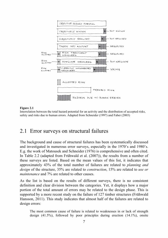
Every engineering task has a hazard potential (Schneider, 1997) which the structural engineer seeks to control. It is of great importance to recognize this hazard potential in order to ensure structural safety. Some hazards are not known, objectively to science in general or subjectively to the individual structural engineer. Some risks may even be ignored in the process. Risks may also be consciously accepted or managed by safety measures (e.g. design codes). This means that every decision will contain residual risks, as illustrated in Figure 2.1.
6
7
Figure 2.1 Interrelation between the total hazard potential for an activity and the distribution of accepted risks, safety and risks due to human errors. Adapted from Schneider (1997) and Faber (2003)
2.1 Error surveys on structural failures
The background and cause of structural failures has been systematically discussed and investigated in numerous error surveys, especially in the 1970’s and 1980’s. E.g. the work of Matousek and Schneider (1976) is comprehensive and often cited. In Table 2.2 (adapted from Frühwald et al. (2007)), the results from a number of these surveys are listed. Based on the mean values of this list, it indicates that approximately 43% of the total number of failures are related to planning and design of the structure, 35% are related to construction, 15% are related to use or maintenance and 7% are related to other causes.
As the list is based on the results of different surveys, there is no consistent definition and clear division between the categories. Yet, it displays how a major portion of the total amount of errors may be related to the design phase. This is supported by a more recent study on the failure of 127 timber structures (Frühwald Hansson, 2011). This study indicates that almost half of the failures are related to design errors:
The most common cause of failure is related to weaknesses in or lack of strength design (41.5%), followed by poor principles during erection (14.1%), onsite
7

8
alterations (12.5%) and insufficient or lack of design with respect to environmental actions (11.4%). In total, about half of the failures are caused by the designer and about one fourth of the failures are caused by the personnel working at the building site. (Frühwald Hansson, 2011)
Table 2.2 Percentage of errors by the phase in which they were made. Adapted from Frühwald et al. (2007)
Reference Planning & design%
Construction% Use/ maintenance %
Othera% Total%
Matousek & Schneider 1976
37 35 5 23 98d
Brand & Glatz 2005
40 40 - 20 100
Yamamoto & Ang 1982
36 43
21 - 100
Grunau 1979 40 29 31b - 100
Reygaerts 1976 49 22 29b - 100
Melchers et al. 1983
55 24 21 - 100
Fraczek 1979 55 53 - - 108c
Allen 1979 55 49 - - 104c
Hadipriono 1985 19 27 33 20 99 a Includes cases where failure can not be associated with only one factor and may be due to several of them b Building materials, environmental influences, service conditions c Multiple errors for single failure case d Should be 100% (authors comment)
8

9
3 Uncertainties in structural engineering
The task of practitioners of structural engineering is to synthesise a solution which meets their clients requirements. Not only must a structure be designed or assessed to be safe but it must meet functional, performance and environmental requirements and be delivered at an acceptable cost. Uncertainties abound in the engineering and in all the activities associated with it. The engineer however must progress his task. Action is required based on predictions followed by decisions taken despite uncertainty. This is the essence of engineering. (Menzies, 1999)
Uncertainty is a perpetual companion to all structural engineers. Through design, we construct imaginary buildings with uncertain geometry; with materials of uncertain strength and quality; to withstand loads and environmental conditions of uncertain magnitude and kind. To this the human factor is added, which means that an uncertain amount of errors and deviations from what was intended, will be incorporated in the end product.
These uncertainties, and the variation of nature, are sometimes obscured to the practicing engineer as design codes and regulations have evolved to regulate and manage some of the most important uncertainties, e.g. loads and material parameters. This facilitates practice, and the engineer in general probably considers this a postulate rather than a disadvantage. Yet, a more general awareness of the uncertainties related to a certain design may improve the performance and reduce undesirable events.
3.1 Categories of uncertainties
When an engineering problem is transformed into a model, uncertainties will be built in and included in this model. These uncertainties are often categorized with respect to their nature. Aleatory uncertainty relates to an intrinsic randomness (statistical variation) of a phenomenon and may be equated to the flipping of a coin or the throw of a dice. Epistemic uncertainty, on the other hand, is an uncertainty related to lack of data, assumptions and simplifications when models are created (modelling limitations). Normally, epistemic uncertainty is considered possible to reduce (through measurements and testing) while aleatory is not
9

10
(Kiureghian and Ditlevsen, 2009, Elms, 2004). It is important to understand that the same uncertainty may be considered as aleatory in one model but as epistemic in another one. This is shown in the following short example:
Picture yourself standing in front of a steel beam that needs reinforcement due to a new and higher load. When this was designed, its designer had to consider the material properties as aleatory. He prescribed a steel quality on his drawing but did not know the exact properties. For you, on the other hand, the material parameters are epistemic as you have the option to cut out a piece of the beam and test it. By doing so, the total amount of uncertainty also may be reduced. If you instead choose not to test the material, you face yet another uncertainty. Because, what if the beam is not manufactured by the material prescribed in the drawing?
This question leads to a third type of uncertainty mentioned in literature, namely ontological uncertainty (Elms, 2004, Brown et al., 2008). This uncertainty relates to the “difference between an engineer’s assumptions and reality” and includes events of surprising character such as; human error and new or unforeseen phenomena. Human error is, as previously discussed; a major source to structural failure and history has taught that new and unforeseen phenomena occasionally lead to disaster. The Tacoma Narrows bridge is a well-known and well documented example of this; the bridge succumbed due to wind induced undulations and twisting of the bridge deck in 1940, short after its opening (Petroski, 1992c). After this, the development of longer span and lighter deck in suspension bridges was slowed down, but ten years after its failure it had been successfully re-designed and rebuilt. This exemplifies how failure sometimes is the only way in which an ontological uncertainty may be detected and eventually accounted for.
Aleatory and epistemic uncertainties are normally regulated and controlled by design code. They are relatively easy to quantify and to incorporate in load and resistance factor design codes such as e.g. Eurocode (CEN, 2010). At least if compared to ontological uncertainty, which due to its randomness and unforeseeable nature often needs a different approach to control. Normally quality assurance systems based on e.g. ISO9001 are used to control human error by means of different types of checking (El-Shahhat et al., 1995, Booth, 2005). The effect of unforeseeable events and accidents can be mitigated by e.g. additional robustness precautions such as vertical and horizontal tying of structural components to enable alternate load paths to avoid disproportionate collapse.
Often these types of precautions prove to be insufficient, as hazards due to uncertain and improbable events continue to occur. Serious and highly improbable events such as e.g.: the New York World Trade Centre terrorist attack on 9/11, 2001 or the tsunami induced nuclear meltdown in Fukushima on 3/11, 2011, are often named “black swans” (Taleb, 2010). The name refers to the fact that these
10
11
types of events are almost impossible to imagine before they have occurred, which in turn gives an explanation to why they are so difficult to prevent or to mitigate.
3.2 Sources of uncertainties
3.2.1 Physical uncertainty
Physical uncertainty is related to the randomness of a basic variable (Melchers, 1999). The physical uncertainty represents the natural variation of a variable. This can be e.g. steel yield strength, wind load, floor loading or the physical dimensions of a structural component.
3.2.2 Statistical uncertainty
When data with a limited sample size is transformed into statistical estimators such as sample mean and distribution functions, a statistical uncertainty is introduced (Melchers, 1999). The true natural variation (physical uncertainty) is unknown and will be estimated from limited sample data (Nowak and Collins, 2012). A large sample size will reduce statistical uncertainty but can normally not eliminate it.
3.2.3 Model uncertainty
Model(ling) uncertainty is a way of describing how well a model describes, or predicts the “real” behavior of a structure or other type of phenomenon. It is often related to lack of knowledge (Melchers, 1999). It may originate from both uncertain parameters within the model as well as from limitations in the model itself. The latter is sometimes referred to as model limits (Möller and Beer, 2004). It “arises in the abstraction process”; when a structure, imagined or existing, and its behavior is transformed into a mathematical expression. This process is always a simplification connected to a degree of uncertainty.
…all calculations, no matter how sophisticated and complex, cannot be more than rough approximations of the natural phenomenon they try to represent by means of a mathematical model… (Candela, 1973)
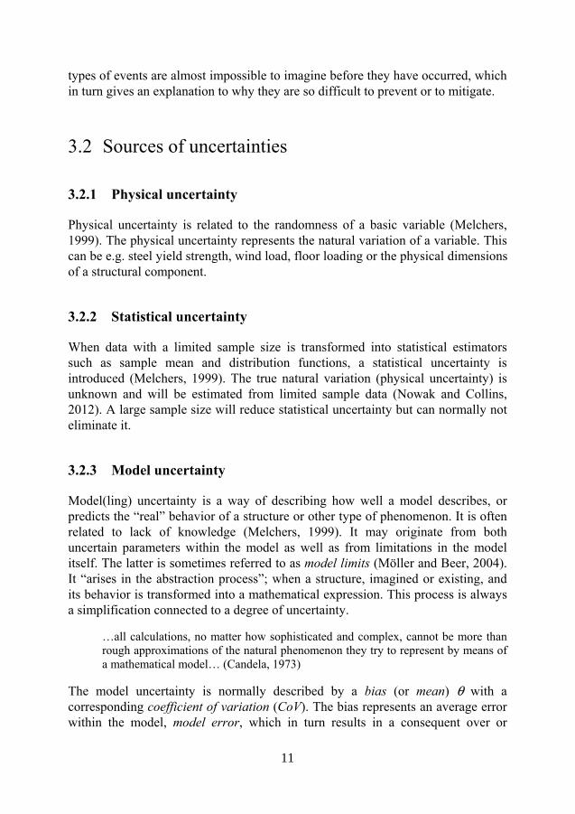
The model uncertainty is normally described by a bias (or mean) θ with a corresponding coefficient of variation (CoV). The bias represents an average error within the model, model error, which in turn results in a consequent over or
11
12
underestimation compared to the real behavior, see Figure 3.1. Equation 3.1 describes how the bias is defined, as the experimental mean Y´ divided by the model prediction Y. = ´
(3.1)
Figure 3.1 Schematic description of model error, adapted from (Melchers, 1999)
According to Bulleit (2008), the model uncertainty is divided into two different parts. The first is defined as “the uncertainty related to how well a prediction equation models test data” and the second as “the uncertainty about how a structure model, e.g. a finite element model, predicts how the structure behaves”. The latter part is a “function of how well the structural engineer models the structure”. This means that subjective decisions related to the engineer’s knowledge, available time, tools and the complexity of the structure, will affect the level of uncertainty.
The Joint Committee on Structural Safety, JCSS (2001), describes how to account for model uncertainty in (i) load calculations models, (ii) load effect calculation models and (iii) local stiffness and resistance models. Neither of these categories includes nor addresses the human effect as suggested by Bulleit (2008).
In order to avoid confusion, this thesis distinguishes the model (and its correctness) from the human influence (how well models are interpreted and constituted to represent structural systems). The first part will still be referred to as model uncertainty while the second will be referred to as engineering modelling uncertainty, EMU, which is described in detail in Paper I.
3.2.4 Contingency
The practicing engineer is constantly administrating things that are not yet certain – or contingent. These are connected to e.g.: geometrical uncertainties (related to the architect’s, mechanical engineer’s or client’s demands) or limited knowledge
12

13
of geotechnical conditions etc. In Ferguson (1992), engineering design is described to be a “contingent process, subject to unforeseen complications and influences as the design develops”. Over time, the design process has adapted to this, and it is often divided into stages with respect to the projects degree of maturity and level of detail. It may be divided into e.g.: conceptual design, preliminary design and detailed design. It is reasonable to believe that the amount of uncertainty due to contingency is reduced throughout the process. The uncertainty is supposed to be small when the detailed drawings are completed, but not eliminated as e.g. deliberate on site alterations may occur. Bulleit (2008) points out that with the respect of contingency; there is a substantial difference between the work of a scientist and an engineer:
A scientist analyzes systems that already exist; engineers must visualize the system they are going to analyze. The visualized system is obviously not the actual system, so contingency is guaranteed to increase uncertainty. (Bulleit, 2008)
A faulty decision due to uncertainty may always be considered an error in retrospective. Thus, it is important to understand that the work of the engineer, in contrast to the work of the scientist, always is accompanied by uncertainty. “Action is required based on predictions followed by decisions taken despite uncertainty. This is the essence of engineering” as formulated by Menzies (1999). This in turn means that an error which occurs as a result of uncertainty, e.g. from limited knowledge or contingency, early in the process, should not be treated as a design error if the adoptions and conditions of the calculation are rationally applied and properly documented; instead this error is related to the process and perhaps rather is an error of communication or quality assurance. This creates a gray area between objectively correct answers and gross errors.
This is supported by decision theory, where a distinction between right and rational decisions are made (Peterson, 2009). A decision made at a certain time, with limited input, may still be considered rational if all available input is used and assessed correctly, even if the result leads to an error (or a decision that is not right). Hence, it is important to distinguish an error due to incomplete or uncertain information, from a gross error – unless the lack of information itself is related to ignorance or omission.
3.2.5 Engineering knowledge and performance
3.2.5.1 Training and education
There is probably no practicing engineer who would claim to possess complete knowledge of the field of structural engineering. As both science and technology constantly evolves, probably no one will ever do. This means that we always have
13

14
to accept an uncertain gap between what is objectively known and subjectively realized (see Figure 2.1). This dilemma was mentioned already by Brooks (1967):
To the professional belongs the responsibility of using both existing and new knowledge to provide services that society wants and needs… and action must always be taken on the basis of incomplete knowledge. (Brooks, 1967)
3.2.5.2 Experience, expertise and conceptual understanding
It takes time for a practitioner to develop sufficient experience to fully master his or her craft. The 10-year rule is an established expression within cognitive psychology and concludes that it takes approximately 10 years of dedicated work to fully master a field that requires creativity (Weisberg, 2006). This rule originates from a study on chess players (De Groot, 1978) but is considered to be valid also for a number of scientific professions, e.g. physicists, which is about problem solving and hence requires creativity and the ability to combine different parts of knowledge.
According to Chi et al. (1981) there is a difference between how an expert solves a problem compared to how a novice solves the same problem. Typically the novice solves the problem at a “surface level”, based only on the available information – the “objects involved”. On the other hand, the expert has the ability to solve the problem and to elaborate a richer understanding of it, based on the underlying principles of the problem. Chi’s study included a comparison between experts and novices of physics, but it is reasonable to believe that it holds also for structural engineers. Weisberg (2006) concluded the characteristics of the performing expert as follows:
Experts have developed knowledge that enables them to analyze a problem at what one would call the conceptual level, and thereby focus on the relevant components of the problem. (Weisberg, 2006)
This ability to analyze and understand a problem at a conceptual level is referred to as conceptual understanding in Paper II and III.
When entering the profession, structural engineers have approximately spent three to five years in their studies of applied science (bachelor or master level). By combining this with the 10 year rule, it is reasonable to believe that it takes at least five to seven years of practice to master the craft. At this stage the practitioner does not necessarily has become an expert, but has developed an experience level that enables him or her to independently contribute in a creative manner and to solve problems on a conceptual level.
3.2.5.3 Time
An increase of time to decide will reduce uncertainty (Bulleit, 2008). This is reasonable to a certain point, when additional time will have no or only limited
14

15
effect on the level of uncertainty. Too long decision time will be both inefficient and costly.
The concept of Efficiency-Thoroughness Trade-Off (ETTO) is used in resilience engineering (Hollnagel, 2009). A practitioner often faces the challenge to balance efficiency with thoroughness and needs both “time to think” and “time to do” in order to perform an action with acceptable accuracy. When the time available is less than the sum of the “time to think” and “time to do” a trade-off is required. If the “time to do” is prioritized, the level of uncertainty will increase.
3.2.5.4 Subjectivity and different opinions
Disagreements among engineers regarding how to interpret theories and design codes are common. These may take place in the design process, especially when different engineering firms interact in the same project; but more frequently this occurs after the design process, when the building already has been, or is being erected. At this time the dispute often relates to an economical dispute due to the impression of an overly expensive design or, to the other extreme, a structural failure. The latter may be hard to defend if the structure has been constructed according to the final drawings. In this case it is highly probable that a design error is committed – compare with section 2.1. The former, on the other hand, may be related to subjectivity and differing opinions regarding best practice and how to interpret e.g. the design code. This in turn may be related to a number of aspects, such as e.g. limited, unclear or inconsistent code prescriptions or at its worst, as a result of deliberate negligence.
Honfi (2013) describes a differing opinion among Swedish structural engineers about deflection limits, as a result of incomplete code prescriptions and ultimately the lack of scientific knowledge on how to deal with these issues in a consistent manner. The 19 practicing engineers interviewed in his study, presented a large variety of deflection limits and rules of thumb, but no clear consensus. Honfi concludes the following:
There is an uncertainty among designers how to design in the serviceability limit state; a mixture between practice, handbooks and regulations is adopted. (Honfi, 2013)
A similar problem occurs in the design for robustness against disproportionate and progressive collapse for buildings. This issue is discussed by Nygårdh and Niklewski (2013). In this case the problem is related to how different engineers and manufacturers of precast concrete components interpret the code in different ways, and more crucially, which parts of the code to follow; as both EN 1991-1-7 (CEN, 2006) and EN 1992-1-1 (CEN, 2005) regulate this issue and are partly contradictory.
15

16
3.2.5.5 Variations and errors
Two engineers performing the same design task will not end up with exactly the same result. Input (e.g. drawings and design codes) is processed and interpreted differently, values are rounded, different models are chosen and other simplifications are made. Due to this, normally a correct solution is not obtainable. This means that an acceptable solution (connected to a range) is more appropriate than a single value. Values outside of this range may be considered errors.
Hambly’s paradox is an example of how difficult it is to find the correct solution to a redundant structure. It was introduced by Edmund Hambly, who was a structural engineer and former president of the Institution of Civil Engineers. The example concerns how the forces are distributed between the legs of a four legged stool and what load each leg should be designed for (Heyman, 1996). Based on the assumption of a man weighing 600N sitting on the stool, Heyman discusses this problem with respect to elastic and plastic analysis and also takes instability into account. All methods result more or less in a design load of 150N for each leg, whereas the experienced structural engineer quickly realizes that this problem is not the stool itself but rather its boundary conditions. A slightly shorter leg or an uneven floor will at times mean that the load will be carried by only two of the legs, which in turn means that each leg must be able to carry at least 300N.
Many practitioners would suggest that the most correct solution to a problem is achieved by using as many significant figures as possible during the calculation process. This, though, is a bit delusory and will suggest the result of each step to be more accurate than it actually is (Chancey et al., 2005). It also promotes the use of too accurate numerical methods and models (e.g. finite element calculations) despite inaccurate input. The principle of consistent crudeness (Elms, 1985) though illuminates this and points out that the “the level of detail in any part of an engineering procedure must to some extent be governed by the crudest part of the procedure”.
It is important to distinguish between this type of variation and errors – even if a too large variation within practice may lead to reduced structural safety. Nowak and Carr (1985b) make this distinction between variation and errors as follows:
The two major categories of uncertainty which cause failure are variations within accepted practice and departures from accepted practice. This second category will be called human error. The variations within accepted practice include natural hazards, manmade hazards, variations within common practice, and departure from common practice. (Nowak and Carr, 1985b)
Scientific data on the degree of variation in professional performance are relatively scarce. To the best of the authors knowledge, this is limited to one survey in Australia (Stewart and Melchers, 1988) and one in Switzerland (Bürge and
16

17
Schneider, 1994). In addition, Paper I and II of this thesis present the result from a survey on Swedish structural engineers. The results from these surveys are presented in Table 3.1. An interesting finding is that the coefficient of variation CoV increases with structural complexity. It is naturally so as the number of uncertain variables and degrees of freedom increases, but more importantly the quality of the result of the statically indeterminate 3D system is heavily reduced.
Table 3.1 Table listing variability (CoV) of load effect from surveys on practicing structural engineers
Survey Statically determinate structure
Statically indeterminate structure (2D)
Statically indeterminate system (3D)
Applied Design Load
Stewart & Melchers - 19%a - -
Bürge & Schneider - 18%b - 9%
Fröderberg & Thelandersson
- 14%-31%c
27%-33%d
78%-83%e
18%c
24%d,e
Fröderberg 8%f - - 8%f
a Bending moments of a steel portal frame (Stewart and Melchers, 1988) b Design value of column load supporting a concrete slab (Bürge and Schneider, 1994) c Design load on foundations (columns) from a deep beam on three supports (Paper I) d Design shear force on foundations (stabilizing system of a five storey concrete building) (Paper I) e Design moment on foundations (stabilizing system of a five storey concrete building) (Paper I) f Support reaction from a steel truss (Paper II)
3.3 Summary
The different types of uncertainties and their mutual relationship are summarized in Figure 3.2, as a function of time in the design process. It is visualized how gross errors are distinguished from the rest of the uncertainties and that a larger level of uncertainty must be accepted for decisions made at an early stage of the design process. Uncertainties related to engineering knowledge and contingencies; together represent the engineering modelling uncertainty, EMU. The remaining uncertainties; physical, statistical and model uncertainty, are normally handled by the design code, while EMU together with gross errors have to be recognized and handled separately, through quality assurance or supervision.
17

18
Figure 3.2 The total level of uncertainty, as a function of time and different types of uncertainty. Dark gray area represents uncertainty covered by design code. Light gray area represents engineering modelling uncertainty, EMU
18

19
4 Human error
Human error has historically always played a role in the engineering endeavors of mankind. Despite its hazardous potential, errors have paradoxically been a fruitful component and driving force of the technical evolution (Petroski, 2006), at least in retrospect. In the last decades of this evolution the consequences of errors in technology has rapidly grown. An error related to e.g. a nuclear power plant may have a very large consequence compared to the size of the facility it stems from. Even a relatively small power plant has the potential to, in a worst case scenario, affect a very large area. Attention was therefore drawn to human errors in the 1980’s, in an effort to mitigate and to prevent large accidents from happening. This resulted in a number of “studies of errors for their own sake” (Reason, 1990).
4.1 Definition of human error
The term human error has no clear and distinct definition within literature. In Table 4.1, a number of definitions are listed, relevant for the subject of this thesis. Most definitions include; departure or deviation from what is considered acceptable or intended, and is caused by human action.
19

20
Table 4.1 Table listing different definitions of human error
Author Definition
Rigby “a human action that exceeds some limit of acceptability” Rigby 1970, cited by (Stewart, 1993)
Bea “a departure from acceptable or desirable practice on the part of an individual that can result in unacceptable or undesirable results” (Bea, 1994)
Reason and Hobbs “…an outcome that essentially involves a deviation of some kind, whether it is a departure from the intended course of actions, departure from a path of actions planned toward a desired goal or deviation from the appropriate behavior at work.” (Reason and Hobbs, 2003)
Douma “any condition that by itself imperils a structure, would cause sudden failure or severely limit the serviceability of the structure, and which could have been anticipated by a competent designer, is the result of a gross error.” (Douma et al., 1973)
Nowak and Carr “unintended departure from accepted practice” (Nowak and Carr, 1985b)
Love and Josephson “deviation from what is intended and caused by human actions” (Love and Josephson, 2004)
Rasmussen “…instances of man-machine or man-task misfits” (Rasmussen, 1982)
According to Reason (1990) human errors may be divided into slips and mistakes. A slip is a result from incorrect execution of a correct sequence of actions, e.g. an engineer who uses a correct formula but incorrectly puts the numbers into his calculator. A mistake, on the other hand, is a correct execution of an incorrect sequence of actions. In this case, the engineer from the previous example instead picks an incorrect or unsuitable formula for his problem and correctly executes the calculation with the erroneous formula.
4.1.1 Human errors, gross errors or gross human errors
The terminology for the human errors, related to structural engineering and structural safety, varies in literature. The terms “human error” (Nowak and Carr, 1985b, Allen, 1986, Frangopol, 1988), “gross errors” (Douma et al., 1973, Ditlevsen, 1983) and “gross human errors” (Melchers et al., 1983) are used alternately. The latter was suggested by Melchers et al. in order to define a consistent description and they define gross human errors to include:
• Error of concept
• Error of calculation
• Error of design
• Error of construction
20

21
• Error of maintenance
Even though human errors and gross errors often are equated (see e.g Canisius et al. (2011)) it sometimes may be relevant to maintain a distinction. By adding gross to error, it is somehow implied that the magnitude of the error is large or perhaps that the attitude of the error maker is questionable (negligence, deliberate omission etc). In Paper I the term gross error is used to mark that there is a gray area between a correct decision (objectively error free) and an indisputable error, due to uncertainties from e.g. the design process and the engineers’ knowledge or experience. Decisions are often made with limited information or knowledge. This means that we have to distinguish between erroneous, rational and right decisions, as discussed in section 3.2.4. A rational decision based on limited information which leads to failure, should therefore not be considered a gross error. On the other hand, the inability to detect this erroneous decision later in the process (if and when the contingency is reduced), may be considered a gross error. Gross error is therefore in this thesis defined by adding “or rational” to the definition of human error from above. Hence, gross errors include: departure or deviation from what is considered acceptable, intended or rational, and is caused by human action.
It is important to realize that this means that gross errors are related to both time (contingency) and engineering knowledge (more is expected from e.g. an expert). A decision may be considered rational if made by an inexperienced engineer but as a gross error if made by an expert. This rather philosophical discussion does not mean that we in general should lower the acceptance level regarding errors leading to failure if the decision is taken by a young and inexperienced engineer. Instead it is reasonable to argue that the responsibility for this particular error should be pushed towards the management of the company at which the person works, which in this case has failed in manning the task.
Dealing with contingency and uncertainty in general in the design and construction process requires feedback loops to assure quality, see Figure 4.1. Design in particular is a cyclic and iterative process which requires quality assurance to cope with uncertainty (Booth, 2005). Therefore it may be argued, that in addition to the five bullet points representing gross human errors listed above should be added: Error of quality assurance. A deviation from a previous decision (or design) is acceptable only if, through a feedback loop, the deviation is re-communicated with the original decision maker. Otherwise uncertainty is induced and control over structural safety is lost. The importance of this is sometimes neglected. E.g., attention was drawn to this after the collapse of the three storey building in Ystad 2012. Even though it was not the primary source of the collapse, the investigation found numerous deviations from the original drawings that had not been documented nor communicated (Karanikas and Dahlberg, 2013).
21

22
Figure 4.1 Flow of building production – with quality assurance feedback loop. Adapted from Sugano (2005)
4.1.2 Constant and variable error
It is sometimes relevant to distinguish between constant (systematic) error and variable error. A constant error may be predictable, or at least traceable, as it is related to a process that produces an erroneous outcome in a consequent manner. A variable error has, on the other hand, a much more random and unpredictable outcome (Reason, 1990). These two types of errors are illustrated in Figure 4.2.
A constant error for a structural engineer may originate from faulty or “buggy” knowledge (individual or developed as practice within a group of colleagues) (Woods et al., 2010a), faulty guidelines or tools (bugs and errors in computer programs are relatively common). In this way errors may be replicated and duplicated. This was mentioned already by Pugsley (1966) who warned against “the frequent adoption of faulty doctrine by a whole profession”, and used the previously mentioned Tacoma Narrows bridge as an example. As no external checking is prescribed in Sweden, faulty tradition may easily develop. This type of error is probably unintended in most cases, but there are examples of e.g. unsound and deliberate misinterpretation of design code that has become developed into “best practice” and then duplicated, especially if the code is incomplete or contradictory as described in section 3.2.5.4.
22

23
Figure 4.2 Variable vs constant errors, explained as target patterns by two shooters, where the first has no constant error but a large variable error; while the second has a considerable constant error but small variable error. Adapted from Reason (1990)
4.2 Design errors
As previously mentioned, design errors are responsible for almost half of all structural failures. Design errors are often related to misinterpretations, miscalculations and omissions (Lopez et al., 2010). From a construction management perspective and based on previous work by e.g. Kaminetzky (1991) and Reason and Hobbs (2003), Lopez et al. (2010) classify design errors with respect to the following characteristics:
• Skill- or performance-based errors, (i.e. slips); (e.g., the plan is acceptable, yet the actions are not performed as planned)
• Rule- or knowledge-based errors, (i.e. mistakes); (e.g., the actions are performed as planned, yet the plan will not achieve the outcome intended)
• Intentional violations or noncompliances; (e.g., to industry or organization imposed norms and standards).
This classification relates well to how human errors in general are considered from a structural reliability point of view (Nowak and Carr, 1985a):
• Errors of concept (i.e. mistakes)
• Errors of execution (i.e. slips)
• Errors of intention
23

24
4.3 Error causes
Human errors in the construction process are related to, and induced by, a large variety of factors. Some are related to technological development and some to “engineering climatology” (Pugsley, 1969). This was identified already by the pioneers of structural safety and reliability. Based on accidents and structural failures from the early and mid 20th century, e.g. Sir Alfred Pugsley distilled a set of often cited “general parameters of significance in accident history” (Pugsley, 1973), that is still relevant:
1. new or unusual materials;
2. new or unusual methods of construction;
3. new or unusual types of structure;
4. experience and organization of design and construction team;
5. research and development background;
6. industrial climate;
7. financial climate;
8. political climate.
According to Brown and Yin (1988) engineers and contractors are equally involved in structural errors, but the severity of the errors committed by engineers widely exceeds those of the contractor. It is concluded that the errors committed by engineers often are “critical and costly”. The engineers’ errors are claimed to be mostly related to insufficient knowledge and incorrect assessment of influences, while the errors committed by contractors rather are dominated by “ignorance, thoughtlessness and negligence”. Brown and Yin summarized the error causes from their studies in the following list:
1. Poor training and pay of field inspectors
2. Inadequate preparation and review of contract and shop drawings.
3. Breakdown or misinterpretation of communications between the design-construction-operation communities.
4. Lack of professional design and construction experience, especially when novel structures are needed.
5. Complexity of codes and specifications leading to misinterpretation and misapplication
6. Unwarranted belief in calculations and specified extreme loads and properties.
24

25
7. Frequent personnel changes.
8. Compressed design-construction time.
When it comes to design errors alone, the comprehensive work of Lopez et al. (2010) concludes that design errors often show as bad quality and erroneous design documentation. These errors may stem from three hierarchically different levels: personal, organizational or project level. Lopez et al lists the following error causes:
Personal:
• Loss of biorhythm e.g. unrealistic schedules lead to stress and fatigue
• Adverse behavior e.g. attitude, awareness, belief, boredom, motivation, self-esteem or trust
Organizational:
• Inadequate training of design consultants e.g. insufficient knowledge, ability and skills
• Ineffective utilization of computer aided automation e.g. overdependence on computer-aided automation by overlooking pragmatic considerations
• Inadequate quality assurance e.g. reluctance to embrace quality assurance and to commit the time required
• Competitive professional fees e.g. too low fees with respect to clients’ demands
Project:
• Unreasonable client and end user expectations e.g. poor communication, due to e.g. lack of common language resulting in difficulty for the designer to: understand the client’s needs, to present design options and to report on what is attainable through design
• Ineffective coordination and integration of the design team e.g. related to procurement method, lack of constructability and complexities associated with communication and coordination of a large number of tasks undertaken concurrently
When the different studies are summarized and compared, a number of factors causing errors re-occur. Among others, errors appear to be related to: lack of review (quality assurance), complexity, lack of knowledge and experience, insufficient communication, faulty use of design tools, lack of time etc. In the following sections a number of those issues will be discussed from the perspective and scope of the investigation on which this thesis is based.
25

26
4.3.1 Insufficient checking or lack of review
As mentioned by Lopez et al. (2010), quality assurance systems occasionally malfunction. According to Love et al. (2008) this may be related to: (i) time pressure (even if it is known that checking adds value, engineers choose not to perform it, this may be compared to the efficiency-thoroughness trade-off (ETTO) discussed in section 3.2.5.3), (ii) concurrent or overlapping design activities (e.g. architectural, mechanical and structural engineering) makes checking difficult or “arduous”. A third aspect would be to mention that, despite its name, the quality assurance in itself normally does not assure that something is correct, but rather it regulates that a task has been performed and checked according to a certain protocol.
Quality assurance has a significant limitation: it assures the quality of management systems, but not of their content. It will ensure that all procedures have been followed correctly, but it will not normally pick up whether the result of the procedure is correct or appropriate. That is why independent checks are necessary. (Elms, 2005)
The quality assurance tradition/ strategy among structural engineers in the house-building sector in Sweden, has in general been that structural calculations are checked by self-checking, while design drawings are checked independently. This is discussed in Paper II, and is problematic in the sense that it is much more difficult to detect a mistake than a slip in a calculation. A slip (e.g. faulty calculator input) would typically produce an unreasonable and easy to detect result, while a mistake (conceptual misunderstanding, e.g. faulty choice of calculation model) would be difficult for the person who has committed the error to detect. This is described as “the reduction of error occurrence is relatively small for self-checking” by Stewart and Melchers (1989a).
It is important to keep in mind that all errors will not be detected by a checking procedure, even though large errors typically are easier to detect than small errors. Even if unlimited time is given, only approximately 85% of the total amount of errors will be detected (Stewart and Melchers, 1989b). In order to be able to detect errors, a degree of experience is also required from the checker; this may question the use of self-checking as the only check for the work of young and inexperienced engineers.
4.3.2 Complexity
Failure, then, represents breakdowns in adaptions directed at coping with complexity. Indeed, the enemy of safety is not the human: it is complexity. Stories of how people succeed and sometimes fail in their pursuit of success reveal
26

27
different sources of complexity as the mischief makers – cognitive, organizational, technological. (Woods et al., 2010c)
4.3.2.1 Advanced computer use
Ever since its appearance, as an engineering tool in the 1960s, the computer has been debated with respect to its effect on design quality, error frequency and magnitude. This is not unique for the computer since other changes of tools has faced similar skepticism, e.g. the development from slide rule to the desktop calculator (Petroski, 1992b). It is important to understand that a design tool or aid does more than just substitute an old tool. In a substantial way it changes the way things are done and contribute to the development of new practices (Woods et al., 2010b). In this process it is inevitably so that old knowledge will be replaced by new knowledge. This is not necessarily a problem, but in the twilight between development stages lays an inherent and increased risk of committing errors until the new tool is fully incorporated in practice.
Because structural analysis and detailing programs are complex, the profession as a whole will use programs written by a few. These few will come from the ranks of the structural “analysts”… and not from structural “designers”. Generally speaking, their design and construction-site experience and background will tend to be limited. It is difficult to envision a mechanism for ensuring that the products of such a person will display the experience and intuition of a competent designer. (James G. Macgregor as cited by Petroski (1992c))
In Paper II the computer and its software is described as a black box. The black box metaphor describes how input is transformed into output via a process with limited or no insight. This is described to have a negative effect on the development of the user’s experience. On the one hand, the development of advanced computer tools has provided the structural engineer with powerful design aids, that enables much faster process and the design of complex structures (Petroski, 1992b); advanced tools also do reduce model uncertainty as they often are able to give a more accurate description of the true behavior of a structure. But on the other hand, the design aids tend to pacify the engineer in the process which in turn makes it harder for him/ her to question the outcome of the analysis and to detect errors due to incorrect input:
should there be an oversimplification or an outright error in translating the designer’s structural concept to the numerical model that will be analyzed through the automatic and unthinking calculations of the computer, then the results of the computer analysis might have very little relation to reality (Petroski, 1992b)
A more advanced tool requires more from the engineer with respect to knowledge and understanding of the theoretical background of the software. It also often requires computer skills, which sometimes lead to that it is relatively young and inexperienced engineers who maneuver the software; this is discussed in Paper II.
27

28
These engineers may have the theoretical knowledge but often lack the experience needed to transform an engineering problem into a proper computational model. This means that the introduction of an advanced tool in a project needs thorough supervision and checking in order to produce a more accurate result, especially if the problem is complex. Otherwise, this complexity will overrule the desired reduction of the model uncertainty. This is illustrated in Figure 4.3.
Figure 4.3 The total level of uncertainty, as affected by the introduction of an advanced tool.
A number of structural failures may be connected directly or indirectly to the use of computer tools. The collapse of the Hartford Civic Centre 1978 (Martin and Delatte, 2001) and the sinking of the Sleipner platform 1991 (Jakobsen, 1994) are some well-known and well-documented examples of this.
To make advanced and complex computer software user friendly reduces certain types of errors. Typically the graphic representation of a structure reduces geometrical errors (input slips) that were common when the programs had no
Oversimplified conceptual models
An oversimplified model is often used when diaphragm structures are analyzed; structures such as e.g. deep beams on multiple supports or slabs, used for stabilizing for horizontal loads, supported by elevator shafts or wind bracing. A tradition among engineers has been developed to use frame-analysis software, and to model the diaphragms as beams. By doing so, the considerable stiffness of the slab or deep beam (compared to its supports) often is underestimated, even if the stiffest beam section of the software package is chosen. The error impact of this oversimplification is discussed in detail in Paper I.
28

29
graphic output. Ironically, this evolution has proven to induce new types of errors. E.g., by making software easy to use, less entry requirements from the user are needed. Basic skills in 3D-modelling are often all that is needed in order to use very advanced finite element software to create structures that may look correct but may lack important characteristics of suitable calculation models.
The operator no longer needs to understand engineering processes or computation to obtain a solution… The relative ease of producing calculations also encourages complexity… this complexity may mask, or even encourage, error. (Gardner, 2003)
According to Scheer (2011), a number of disadvantages with computer use may be listed. Scheer points at e.g. the risks of: (i) bad (complicated) designs, (ii) false sense of correctness, (iii) incorrect use, (iv) variability between engineers due to different perspectives on how to model a particular problem, (v) engineers who use it to solve problems they do not understand, and finally (vi) obscure the fact that there is no “right” solution to a redundant system.
It is important to underline that it is not the computer or the software itself that is faulty. The main problem is rather related to how and by whom the tools are used. New tools mean new processes and new ways of working, which in turn requires new ways of quality assurance.
The evidence suggests that most computer-generated errors come from deficiencies in the modelling process, or a lack of understanding of the limitations of the software, rather than the actual computation or errors in the software itself. (Gardner, 2003)
Practitioners often do not desire the ever increasing functionality and complexity of software; instead they learn to trick automation in an attempt to take “control over technology” (Woods et al., 2010b) and to reduce complexity. When incidents occur due to use or misuse of advanced software aids, the engineer is held accountable, paradoxically as it often is induced by a change or adaption to the software in order to be able to maneuver it and to deliver on time. The advanced systems of the Gulf war showed that the new technology, rather than to simplify work, forced the military personnel to: “do more, do it faster and in more complex
Overconfidence in software
During a peer review process of a large span steel roof structure, the reviewer discovered recurrent under-strength in the bolt connections of the steel trusses. The manufacturer dismissed the issue by referring to the current software used for the design. A more thorough investigation of the software, though, revealed a programming error, which overestimated the shear capacity of the bolts with 67%.
29

30
ways” (Cordesman and Wagner, 1996). Hence, advanced computer systems are obviously sources of errors if not carefully dealt with.
4.3.2.2 Design Code complexity
Science is continuously refining its chart over nature. In a well-intended strive for effective material utilization and sustainable development, design codes evolve accordingly. The modern design codes of today (e.g. Eurocode) have therefore developed into complex regulations that take much effort to understand and master for the practitioner. This intrinsic complexity of Eurocode consist of both a “hard” (from quantity of technical provisions and their cross references); and a “soft” part
Coarse finite element mesh and unfortunate results presentation
A finite element software package was used to derive section forces for a concrete slab. The slab was modelled with shell elements. It was found that this software used an unfortunate technique to present the result values. The stress and force distribution was visualized based on the nodal values, which meant that in areas with abrupt changes of forces (e.g. the shear-force distribution of a continuous slab over a support, where the shear force changes sign), and in combination with a coarse FE-mesh, a significant error was induced as illustrated below:
An experienced engineer would typically reject this result as unreasonable. But in the present case this unexpected limitation of the software was found very late, which resulted in undesirable shear reinforcement and drawing revision.
30

31
(from standardization, needs of stakeholders, codification of standard and interpretation of users), (Angelino et al., 2014). The experienced structural engineer Anthony Hunt, key note speaker at the Nordic Symposium on Structures in Architecture at Ven (Sweden) 24 June 2014, uttered the following:
Codes of practice has become so complex – to the worse… European codes are insane in their complexity.
Similar to the computer software, an advanced design code formula may be very hard to understand. This means that it also may be compared to a black box, with the same effect on the development of experience. This is particularly important when engineering students undertake their studies in structural engineering. Complex expressions take valuable time both from lectures and self-study to master, which risk producing engineers with deep but scattered knowledge if these issues are not carefully dealt with within academia. This is discussed in Paper III.
In times when legal issues and lawsuits are common in the building industry, focus is often on what is described by the code. This is unfortunate; because even if the codes often are comprehensive and complex, they do not cover everything:
The correct view of the relationship between codes and design is not that design is essentially a matter of following codes, but rather, that design should principally focus on those matters not covered by codes. (Elms, 2005)
Both advanced design tools and sophisticated code expressions give a notion of accuracy. As discussed in section 3.2.5, accuracy is governed by the accuracy of input. A precise numerical method cannot improve accuracy of imprecise input. On the other hand, a too crude numerical method (high model uncertainty) can distort and ruin the best of input data. Chancey et al. (2005) stresses that it is the engineers who are responsible to understand the limitations of precision with respect to both design codes and design methodology, and to apply this knowledge accordingly. Even more important is that the presence of human errors in general has a large effect on the relevance of a design calculation. This is mentioned by Brown and Elms (2007) who with this in respect claims that “further precision will not improve accuracy…”.
Complex design code expressions are sometimes difficult to interpret and to use correctly. This means that a complex code expression itself may lead to an increase of error occurrence (Bulleit, 2008). This is supported by Busby (2001), who describes how code and norm, introduced as a result of previous errors, cause new errors. It is though not new to find design codes complex. Already Smith (1976) related the problem with too complex codes to a number of bridge failures.
31
32
4.3.3 Change of personnel
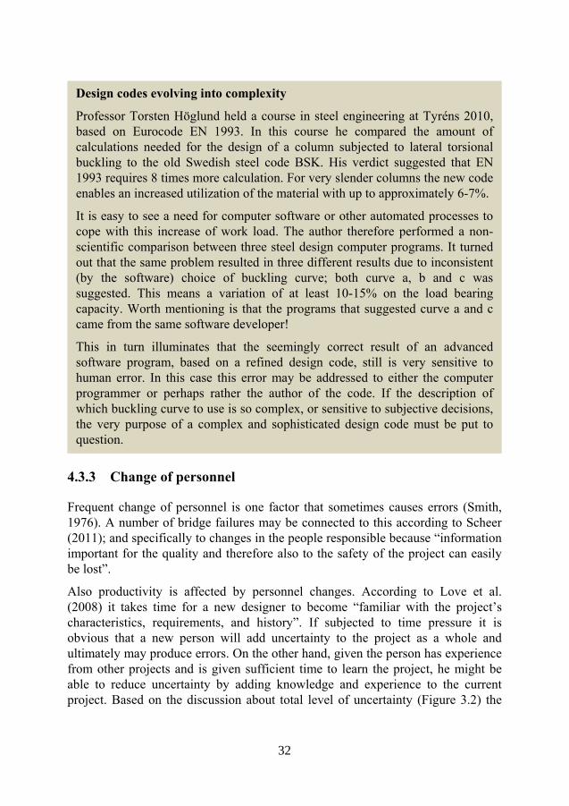
Frequent change of personnel is one factor that sometimes causes errors (Smith, 1976). A number of bridge failures may be connected to this according to Scheer (2011); and specifically to changes in the people responsible because “information important for the quality and therefore also to the safety of the project can easily be lost”.
Also productivity is affected by personnel changes. According to Love et al. (2008) it takes time for a new designer to become “familiar with the project’s characteristics, requirements, and history”. If subjected to time pressure it is obvious that a new person will add uncertainty to the project as a whole and ultimately may produce errors. On the other hand, given the person has experience from other projects and is given sufficient time to learn the project, he might be able to reduce uncertainty by adding knowledge and experience to the current project. Based on the discussion about total level of uncertainty (Figure 3.2) the
Design codes evolving into complexity
Professor Torsten Höglund held a course in steel engineering at Tyréns 2010, based on Eurocode EN 1993. In this course he compared the amount of calculations needed for the design of a column subjected to lateral torsional buckling to the old Swedish steel code BSK. His verdict suggested that EN 1993 requires 8 times more calculation. For very slender columns the new code enables an increased utilization of the material with up to approximately 6-7%.
It is easy to see a need for computer software or other automated processes to cope with this increase of work load. The author therefore performed a non- scientific comparison between three steel design computer programs. It turned out that the same problem resulted in three different results due to inconsistent (by the software) choice of buckling curve; both curve a, b and c was suggested. This means a variation of at least 10-15% on the load bearing capacity. Worth mentioning is that the programs that suggested curve a and c came from the same software developer!
This in turn illuminates that the seemingly correct result of an advanced software program, based on a refined design code, still is very sensitive to human error. In this case this error may be addressed to either the computer programmer or perhaps rather the author of the code. If the description of which buckling curve to use is so complex, or sensitive to subjective decisions, the very purpose of a complex and sophisticated design code must be put to question.
32
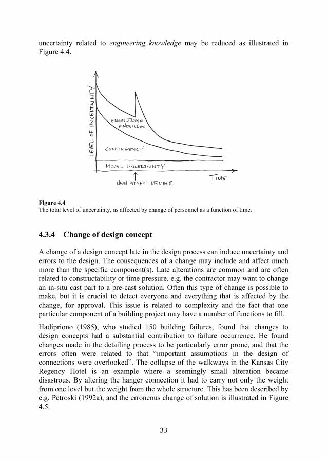
33
uncertainty related to engineering knowledge may be reduced as illustrated in Figure 4.4.
Figure 4.4 The total level of uncertainty, as affected by change of personnel as a function of time.
4.3.4 Change of design concept
A change of a design concept late in the design process can induce uncertainty and errors to the design. The consequences of a change may include and affect much more than the specific component(s). Late alterations are common and are often related to constructability or time pressure, e.g. the contractor may want to change an in-situ cast part to a pre-cast solution. Often this type of change is possible to make, but it is crucial to detect everyone and everything that is affected by the change, for approval. This issue is related to complexity and the fact that one particular component of a building project may have a number of functions to fill.
Hadipriono (1985), who studied 150 building failures, found that changes to design concepts had a substantial contribution to failure occurrence. He found changes made in the detailing process to be particularly error prone, and that the errors often were related to that “important assumptions in the design of connections were overlooked”. The collapse of the walkways in the Kansas City Regency Hotel is an example where a seemingly small alteration became disastrous. By altering the hanger connection it had to carry not only the weight from one level but the weight from the whole structure. This has been described by e.g. Petroski (1992a), and the erroneous change of solution is illustrated in Figure 4.5.
33

34
Figure 4.5 The change made at the Kansas City Regency Hotel that resulted in structural collapse and the death of 114 persons. This alteration was made to simplify the montage of the two-storey walkways hanging from the roof. In the original design, the nut had to be screwed from the bottom of the threaded hanger to fix the position of the upper box-beam. In the actual construction the hanger was divided into two parts, which forced the nut to carry the load from two storeys instead of one. This caused the nut to punch through the flanges of the beam and finally made the walkways collapse.
4.3.5 Time pressure
Time has previously been discussed with respect to its influence on uncertainties. Lack of time may lead to incomplete thought, uncertainty and eventually to errors. In a sense, time pressure is superior to other error causes as it alone can introduce other error causes such as e.g. insufficient checking, lack of communication, over simplifications etc. These are typical examples of efficiency-thoroughness trade-offs (ETTOs). Busby (2001) found that the designers of a complex process plant began to cut corners by neglecting norms (conventions and design codes) when subjected to pressure:
Some of the errors found in this study also showed how readily people will violate conventions if they believe they are unnecessary and they are working under pressure. And it is quite easy to become conditioned to believe that norms are unnecessary if one happens to have had experiences only of events where the norms were not needed. The only robust approach to reducing errors in applying norms is to help designers understand the extent to which they use norms and help them develop a sensitivity to their misapplication. (Busby, 2001)
34

35
Many engineers have experienced how a good night’s sleep has made them realize that yesterday’s decision was faulty. This is sometimes referred to as “engineering conscience” (common expression from the author’s background as a structural engineer). Complex decisions may sometimes require this extra time of reflection. Time is needed to think in order to fully understand the effect of a decision. This is supported by e.g. the thoughts of De Bono (1976), as adapted to human errors in structural engineering by Allen (1986):
A useful experiment to show up the errors in thinking is to try to do things in a great hurry. More mistakes occur because our actions are based on internal patterns triggered off by incomplete information – no time to puzzle over it and fully understand it. (Allen, 1986)
4.3.6 Communication and documentation
Communication within building projects has a large influence on error rate and design quality. This is mentioned in numerous publications, e.g. Douma et al. (1973), Allen (1986) and Chou (2005). Flow of information needs to be well defined. It is not only the direct communication between designers, spoken or written, but also the way decisions from the design process is preserved and made accessible. Proper documentation is the key to every quality assurance system, but experience has shown that background information and documentation (e.g. calculations) sometimes is missing or difficult to interpret. This can create both inefficient solutions as well as errors due to lack of information.
A lack of information about the project and especially the end product may cause a lack of knowledge of how a specific task fits into the total project. This may hinder the creation of a shared mental model and may contribute to suboptimization in projects. (Love and Josephson, 2004)
In Busby (2001), an extensive description of the difficulties in the interaction of different designers, is given. Busby studied 75 errors related to the design of a complex process plant. 27 of these errors were related to the interaction between participants, such as e.g. omissions of: involving others in decisions, to tell about assumptions, understanding how decisions affect others etc. According to Chou (2005) the space shuttle Challenger accident could have been avoided if the report on the condition of the O-rings, that were found to be the cause of the accident, had been communicated to “the proper level of management”.
35

36
4.4 Human error and structural safety
Structural safety is often quantified by using structural reliability measures such as e.g. probability of failure pF or the corresponding reliability index β. Design codes, based on reliability theory are calibrated against these values in order to achieve a certain level of structural safety. In Sweden target β is chosen to be 4.8 for a reference period of 1 year (Boverket, 2013) which in turn represent a pF ≈ 10-6. It is important to know that these values do not represent a real probability of failure, as e.g. the effect of human error is not included and covered by the design code (Frangopol, 1988, Melchers, 2007). Structural safety with respect to human error is instead normally assured and controlled by quality management systems.
4.4.1 Modelling of human errors
Human errors in the design process have been modelled and simulated in a number of studies by e.g. Frangopol (1988), El-Shahhat et al. (1995) and De Haan et al. (2013); in attempts to create measures of their impact on structural safety. Stewart and Melchers (1988) rather successfully managed to simulate the results from a survey performed on structural engineers – the design of a steel portal frame – by performing a Human Reliability Assessment (HRA). Stewart and Melchers modelled the design task by dividing the process into micro tasks. These tasks were given error rates, which represented the probability that an engineer would fail to perform a given task. A Monte Carlo simulation was then used to calculate the probability of failure for both the “error free” and “error included” situations. For one specific load combination, due to frequent misunderstanding of the wind loads, the difference between the error free and error included probability of failure pF, was five orders of magnitude. This is similar to the result presented in Paper I, where pF differed with four orders of magnitude, when the “real” probability of failure was compared to the one regulated by code.
To simulate the effect of human error is possible from a mathematical point of view. A lack of data on human error and occurrence may though limit the relevance of such estimations. To assess the human reliability and its effect on structural safety, the design process must be well defined and ultimately the personality of the “humans” within the process must be known in order to be able to predict their behavior. On the other hand, Vrouwenvelder et al. (2009) suggests that for design purposes, “it seems to make more sense to make overall estimates of the error type and probabilities, even if a great degree of subjectivity is involved”. From a decision making point of view, it therefore may be possible to compare different solutions and optimize them with respect to the influence of human error.
36

37
5 Field study on practicing engineers
5.1 Literature
The literature review that preceded the formulation of research questions and hypotheses, and later the test setup, is summarized in the previous chapters, as a presentation of the topic of interest. Due to the magnitude, complexity and cross-disciplinary character of the topic, this was performed as an overview rather than an in-depth analysis of previous research and knowledge. The most important finding of this review was that, to the best of the author’s knowledge, only two studies on variability of performance, has previously been performed on practicing structural engineers; (Stewart and Melchers, 1988) in Australia and (Bürge and Schneider, 1994) in Switzerland. Much has happened since those investigations with respect to technology, computerized design aids and the development and introduction of new design codes, e.g. Eurocode (CEN, 2010).
5.2 Overview of method and setup
The choice of methodology for this study was based on both the positivist paradigm (based on empirical facts from the tradition of natural sciences) and the interpretivist paradigm (how people interpret the world) (Williamson, 2002). The first, and positivist part, consisted of a quantitative (and to some extent qualitative) data collection part, a round-robin investigation where a number of practicing engineers individually executed two engineering calculation and design tasks. This part was designed to investigate the performance of practicing engineers in a professional context, and was also combined with a questionnaire in order to gather background information of the participants. In the second, and interpretivist part, the participants were interviewed about their everyday work and also with respect to the results of the performed round-robin investigation. This also enabled to gain a better and deeper understanding of the results and to raise new questions based on the quantitative part. The setup is visualized schematically in Figure 5.1.
This combination of data-collection methods, or triangulation of methods, was found to be the most suitable way to investigate the engineer in practice. In Williamson (2002) it is described how “conclusions are likely to be more reliable
37

38
if data is collected by more than one method and from the perspective of more than one source”. A quantitative measure of performance alone is of limited value, especially if the conditions and background are unknown. As discussed in section 3.2.5, performance may be affected by a number of factors such as e.g. education, experience and time available to solve a task. This is of particular interest if the result of this investigation is to be used for: (i) the development of strategies to enhance performance and (ii) to reduce the effect and/ or frequency of human error. As a whole, the quantitative element of this investigation supports an over-all qualitative study.
Figure 5.1 Schematical description of the test setup for the field study on practicing structural engineers.
It may be argued, that the test setup sequence is reversed from a strict traditional research methodology point-of-view. The first, quantitative (deductive reasoning) part is normally used to verify or falsify hypotheses; while the second, qualitative (inductive reasoning) part normally is used to define hypotheses, as conclusions are drawn on a general level, which leads to general relationships and conclusions. On the other hand, in this case the qualitative part was used to complement and deepen the understanding of the outcome of the initial quantitative part on a more general level. It was also used to define new and more general hypotheses regarding the practicing engineer.
Questions and hypotheses
Test 1 Test 2 Question-naire
Pilot Pilot Pilot
Quantitative results
Analysis of results
New questions
Semi-structuredinterview
Conclusions and test of hypotheses
Qualitativeresults
New hypotheses
38

39
5.3 Hypotheses and questions
A number of hypotheses (H) and questions (Q) were defined before the investigation; some of which later was found difficult to verify or answer. The main purpose of these hypotheses and questions was to aid the design of the quantitative, first part. On the basis of: literature studies; the authors experience from practice; and discussion with the projects reference group, the following six hypotheses and questions were formulated:
H1 The engineer’s experience level affects the choice of methodology to solve a problem.
Q1 Will more experience result in simpler models?
H2 An increased use of advanced tools affects engineering practice.
Q2a Do advanced tools prohibit creativity and the ability to think “outside the box”?
Q2b Do advanced tools prohibit the development of understanding of structural systems and the ability to critically question and assess plausibility of calculation results?
H3 Professionals solve problems differently.
Q3a Will the result have a large variability despite a well-defined task?
Q3b Do co-operation and discussion with colleagues reduce the variability of result and error rate?
H4 Engineers’ communication skills are limited.
Q4 Do engineers clearly report what their results represent, and under which circumstances they are valid?
5.4 Participants
The test was submitted to a total number of 17 participants, including one pilot test person. They were all working at medium to large engineering companies and mainly in the three largest cities in Sweden: Malmö, Göteborg and Stockholm. In total 23 companies (or rather the managers of local departments of companies) were contacted to participate, and informed about the investigation in a personal letter. 17 of these chose to participate. The letter gave instructions to the managers regarding the desired profile of the participants, which included that he or she should have at least five years of design experience from structures in concrete,
39

40
steel and timber and preliminary design. The background to why five years is set as a minimum is explained in section 3.2.5.2.
It was clearly stated that the test should not be considered as an exam – it was important for all the participants to feel comfortable in the situation of the test. The manager was asked to pick a suitable person for the investigation. In order to assure a high return rate and to further enhance the impression of real design tasks, the participating companies were financially compensated for up to 8 hours of work per task with an hourly fee of 850 SEK. The time limit was set after a discussion with the projects reference group (with representatives from the building industry) and agreed upon to be reasonable for the present tasks.
It may be argued that the combination of the manager picking the participant and the financial compensation for the work, may introduce bias to the selection of participants. This bias can be introduced in mainly three different ways; (i) as this is a work that will be scrutinized; the manager may want to perform well and therefore pick the very best engineer among the personnel (high focus on quality), (ii) as the remuneration has a limit, the manager may pick the person who is believed to solve the tasks the fastest (less focus on quality), and (iii) a person without the specified requirements, but with little to do, may be picked (no focus on quality).
On the other hand, the manager faces the same possibilities in reality, and therefore this way of selecting the participants was considered to give the best and most representative sample of the population. In contrast, a random sample of e.g. all practicing engineers in Sweden would not be representative, as the present tasks require a relatively high degree of specialized experience and knowledge.
Each participant was contacted in order to select a suitable time schedule for his or her participation. An individual time schedule was chosen in order to avoid collision with deadlines or heavy work load. Typically the participant received the test material for the first task on a Monday morning and was then asked to return the answers the following Friday evening.
Each participant was given a three character code starting with “q2w” in order to ensure anonymity. The reason for a code instead of a digit was to limit the effect of a participant falling off somewhere along the test cycle leaving an empty digit. The code will also limit the possibility to mix up the results for different participants between the tests. The code “q2w” resembles the same participant in both tests which enables comparison of result between the tests. An overview of the 17 participants and which parts each participant completed is presented in Table 5.1.
40

41
Table 5.1 Overview of the participants and which parts of the investigation each person completed.
Participant Test 1 Test 2 Questionnaire Interview Comment
q2w - x - - Pilota
w3e x x x x 1st test-cycleb
e4r x x x x 1st test-cycle
r5t x x x x 1st test-cycle
t6y x - - - 1st test-cycle
u8i x x x x 1st test-cycle
s3d x x x x 1st test-cycle
d4f x x x x 1st test-cycle
g6h x x x x 1st test-cycle
k9l x x x x 1st test-cycle
a2s x - x - 1st test-cycle
z2x x x x x 2nd test-cyclec
x3c x x x x 2nd test-cycle
c4v x x - x 2nd test-cycle
v5b x x x x 2nd test-cycle
n7m x - x - 2nd test-cycle
m8l x x x x 2nd test-cycle
Sum 16 14 14 13 a Performed March-April 2012 b Performed May-July 2012 c Performed September-October 2012
5.5 Round-robin investigation
This investigation was performed using the experimental methodology called “round-robin test”. This method is sometimes also called “profiency testing” or “laboratory performance studies” (Hund et al., 2000). The term “round-robin” is the common term when this method is used to compare how well scientists and engineers predict reality with respect to e.g. (i) structural behavior of concrete (van Mier and Ulfkjœr, 2000) and (ii) fire simulations (Rein et al., 2009). Thus, the term “round-robin” was found appropriate for the current investigation and is used herein.
Round-robin is a method which means that the same test or task is performed multiple times by different scientists or laboratories – or as is in this case by different structural engineers. It is used to measure reproducibility of a method or
41

42
process, or to verify a new type of analysis method. In this case it was used to assess the variability in performance between structural engineers.
A round-robin investigation may be performed in a number of different ways (Rein et al., 2009), e.g.:
• Blind (or a priori), only the initial information about the experiment is given
• Open (or a posteriori), also the results from the experiment is given
• Specified, where e.g. an input file is given
For the present study the “blind” or “a priori” approach was chosen, as the main interest for this investigation lies in how different engineers interpret and process the same initial information.
Typically a round-robin investigation is connected to a specific experiment with real data on physical behavior. As the present study focuses on the design process and structures not yet built, no data of this kind were available. This in turn means that no “correct solution” or “real response”, exists. In its place, a detailed non-linear finite element analysis was performed (Alsuhairi and Hedström, 2013) in order to assess the result of test 1, as presented in Paper I.
5.5.1 Test 1
The first task was designed to resemble a part of a design-build contract project. The project is a five storey semi-precast concrete building in Malmö, Sweden. The first floor will hold public spaces e.g. a restaurant and the remaining four floors will be used for student apartments.
We imagine the following situation:
The engineer (participant) is contacted/ hired by the main contractor (already hired for the project) and is asked to assist him in the design of the building. Initially this commitment means a preliminary structural analysis of the structure: assessment/ checking of dimensions (as suggested in the architectural drawings), load take-down calculation and stability check. This is to provide a good picture of the behavior of the super-structure, which is essential for the first construction step - the installation of the piles. This step will be performed by a sub-contractor; which bases his design on the calculations made by the participating engineer. The super-structure will eventually be detailed designed by another sub-contractor - a pre-cast concrete manufacturer, which at this stage not yet is contracted.
The building is illustrated in Figure 5.2, and the conditions for the task, and how they were presented to the participants, are compiled in Appendix A.1. As this material mainly consists of architectural drawings, the predominant challenges for
42

43
the participants were to: (i) interpret this material and (ii) to transform it into a computational model. The first part involved a number of available decision paths and sources to uncertainty, as for instance:
• The façade material is not described – should a light or heavy weight (brick) alternative be chosen.
• Little is known about the geotechnical conditions apart from the fact that the super-structure requires pile-foundations. It is e.g. not explicitly described whether or not the soil can support a thin floating concrete slab, or if additional support is required.
The second challenge for the participants was to transform the drawings into a computational model, which in turn may be conceptually categorized with respect to its level of detail. The engineer may choose from a number of different options, ranging from simple hand-calculations to advanced three-dimensional finite element calculations, in order to solve the problem. As the time was limited, the engineer had to assess and evaluate which level of detail to pick, in order to create a sufficiently accurate model. As in a real design situation, he or she had to wisely trade efficiency for thoroughness (ETTO), (Hollnagel, 2009). This decision may also be affected by tradition, experience and education.
Figure 5.2 Rendered picture of the building in Test 1.
5.5.2 Test 2
Compared to task 1, the second test was designed to resemble an even earlier stage of the design process – the conceptual design stage. The project is an indoor sports arena in Arboga, Sweden.
43

44
We imagine the following situation:
A property developer is planning for a new indoor sports arena. He has hired an architect to create a set of preliminary drawings for his estimation of the investment costs, and the application for a building permit. In turn, the architect contacts a structural engineer (the participant), to study the roof structure. It is the engineer’s task to (i) suggest the geometry of a cost efficient steel roof structure, (ii) estimate the steel weight of the truss (for cost calculations), (iii) estimate the load effect on the supports (input for the preliminary design of the pre-cast concrete structure) and finally (iv) to roughly sketch an alternative timber solution. A section through the building is presented in Figure 5.3.
Figure 5.3 Principal section of the indoor arena of test 2 (architectural sketch)
The conditions for the task and how they were presented to the participants is compiled in Appendix A.2. In this case, the biggest challenge was in the creative part of the process – to conceive an efficient form for the structure. The participant could choose different paths to find this form, such as: rules of thumb, e.g. Ruddy and Ioannides (2004); iterative hand-calculations; manual iterative computer calculations; graphical form-finding, e.g. Allen and Zalewski (2009); or numerical form-finding and optimization techniques, e.g. Lee and Geem (2004) or Coenders (2008).
5.6 Questionnaire
A questionnaire was used to obtain a clear picture of the participants, their background and how they perceived the round-robin test, see Appendix B. The background questions covered: experience level (number of years and types of projects), education, and office size.
The questions about the tests were designed to give (i) a measure on how they were experienced: if they resembled tasks performed earlier, if time was enough, if they were unclear in any respect, and if they were perceived as real tasks; and (ii) a
44

45
picture of how they were solved: if the solutions had been discussed with a colleague and if computer based tools had been used. These questions were designed as yes/no questions, but in relevant cases it was possible to clarify and specify the answer.
5.6.1 Remark on anonymity
Unfortunately, it turned out that the phrase “dina svar och din medverkan i denna undersökning behandlas helt anonymt” (in English: Your answers and participation in this investigation is treated anonymously, see Appendix B), was used incorrectly; as anonymity means that the respondent’s identity is unknown to the person collecting the data, see e.g. Ejlertsson (2005). Confidentiality would have been a more correct word to use, which on the other hand was possible to understand through the description of the procedure. In Hermerén (2011), though, “anonymizing of information” by “cutting away personal information”, is suggested to ensure anonymity which indicates that the formality was correct from an ethical point of view.
5.7 Interview
In this case a naturalistic semi-structured interview (Ryen, 2004), was chosen to qualitatively study the views of the participants. The naturalistic interview means, according to Ryen, that: (i) the interviewee’s interpretation represents the truth/ her reality, (ii) the results are probably true, and (iii) you get access to the interviewee’s experiences through questions and the content of her story. This is the preferred choice for interpretivists as they (we) are “concerned with meaning”, and that the “social world is interpreted or constructed by people and is therefore different from the world of nature” (Williamson, 2002). The interview is therefore a useful tool to measure this “social world” and how people interpret it.
A number of thematic questions where defined for the interview. These were based on the initial hypotheses and questions as well as the new questions, raised from the results of the quantitative part. An extensive description of the theme questions is presented in Appendix C. The main themes of these questions are as follows:
• Early design stages It was discussed how the interviewee works/ wants to work at this stage, and how much he/she can influence the outcome.
• The test The compiled result from the test series was presented and discussed
45

46
• Calculations Different models may result in different answers and it was discussed how the interviewee choses his/ her models, if different models are used in parallel, experience from the use of Eurocode. At this stage, specific questions regarding the interviewee’s test results were clarified.
• Quality assurance (QA) QA and interaction with colleagues in daily work was discussed; how does drawings and calculations get reviewed – and are you pleased with this, do you have guidelines for calculation documentation and do you have a lot of interaction and discussion among colleagues?
• Structural failures In the light of a number of spectacular structural failures in Sweden, it was discussed how these events had affected the interviewees, if they had made them anxious about their own projects and why so.
All but one interview were held face to face in the interviewee’s office, the exception was carried out via telephone. All interviewees agreed to be recorded through a recording device. Parallel notes were taken. In total 13 interviews were performed with a length ranging from 51 minutes to 1 hour 27 minutes. Mean length of interview was 1 hour 4 minutes.
It is important to keep in mind that the interviewer shared the profession of the interviewees. This was known to the interviewees and may raise a number of questions concerning the validity of the results, as it has a potential of adding bias to the results and answers. Every effort was made, from the interviewer’s perspective, not to let past experience color the assessment of the interviewees’ answers. Still there is an inherent risk that the interviewees adjusted or exaggerated their answers in attempts to give “correct” answers according to what they believed the interviewer wanted to hear and what he sought. On the other hand, the shared profession also meant that it was much easier for the interviewees to communicate their experience and answers to the interviewer. Due to a mutual jargon and technical language, the risk of misunderstanding was kept at a minimum.
5.8 Results
5.8.1 Quality of presentation
The quality of the returned results varied considerably with respect to level of detail, explanation of what the presented values represent and readability. In order to compare the quality of the presented results with this respect, three criteria are
46

47
defined; General account of results, Answer to asked questions and Clarification of assumptions. The first criterion assesses the overall appearance and readability; the second is test specific and checks if the questions asked actually are answered; and the last checks the clarity of what the results represent, and if the question is understood correctly. These criteria are divided into three groups for each test with five sub-criteria respectively:
Test 1
General account of results
1. Report
2. Calculation
3. Results compiled
4. Figures for clarification
5. Basic assumptions (i.e wind terrain type, snow zone etc)
Answer to asked questions
6. Check of concrete dimensions
7. Column dimensions
8. Loads on pile-foundations
9. Stabilizing load – moment
10. Stabilizing load – shear force
Clarification of assumptions
11. Clarified which code that is used
12. Clarified if characteristic values or design values was used
13. Clarified if the load from foundation slab is included in result
14. Clarified if the load from façade is included in result
15. Clarified how the building is stabilized in the longitudinal direction.
Test 2
General account of results
1. Report
2. Calculation
3. Results compiled
4. Figures for clarification
5. Basic assumptions (i.e wind terrain type, snow zone etc)
Answer to asked questions
6. Sketch of steel truss
7. Dimensions reported
8. Steel weight of truss
9. Loads at supports
10. Sketch for timber alternative
Clarification of assumptions
11. Clarified which code that is used
12. Clarified if characteristic values or design values was used
47

48
13. Clarified how the temperature load is managed
14. Clarified of how the steel truss is stabilized against buckling
15. Clarified assumption of load on bridges
Each criterion is assigned with a result value, 0 or 1. This ends up with a maximum conceivable score of 15, for each test. The bold bullets above are considered the most important factors to ensure the quality of the result, according to how the tasks are defined (with all their uncertainties etc). A three-degree scale is suggested to evaluate the quality of the presented material. Based on the presented criteria this scale is defined as:
Satisfactory: Requires total score of 11 and 8 bold points
Somewhat unclear: Requires total score of 8 and 6 bold points
Unclear: Below 8 points or below 6 bold points
The outcome of this assessment is presented in Figure 5.4 for each test. Despite that this is a simplified and somewhat subjective assessment; it still indicates that the majority of the presented results are unclear to some extent. Some criteria are more important than others with respect to structural safety. Worth mentioning is e.g. that 8 of 16 participants failed to clarify in test 1 if their presented values were characteristic or design values. This was though much clearer for test 2, where only 3 of 14 participants failed to clarify this. It may be argued that this is of limited importance as typically the receiver of the result would assume an unspecified value to represent a design value. As two of the result sets from test 1 were presented as characteristic values, this assumption may prove to be wrong, even though these particular sets were clearly defined. This means that under certain circumstances (when two engineers with different opinions on what is common practice, collaborate) the design load may be either over or underestimated. This type of uncertainty is totally unnecessary as the sender of the result information easily can eliminate it.
Figure 5.4 Quality assessment of presented material from test 1 and 2
0
5
10
unclear somewhatunclear
satisfactory
Fre
quen
cy
Quality of presentation test 1
0
5
10
unclear somewhatunclear
satisfactory
Fre
quen
cy
Quality of presentation test 2
48

49
5.8.2 Test 1
The result from test 1 is summarized and given a detailed discussion in Paper I. The summarized result values show the essential components relevant for the thesis but due to the limited format of the scientific article, the reader may miss certain data. A comprehensive data assembly is therefore provided in Appendix D.
5.8.2.1 Concrete dimensions
In general the dimensions suggested in the architectural drawings (concrete walls and slabs) were found sufficient. This enables and makes a further comparison of load results relevant.
The suggested dimensions of the concrete columns were also relatively uniform. With few exceptions the participants found a pre-cast 300x300 mm column to be sufficient. One major exception was suggested from one participant (700x700 mm²). This is questionable, but was found rational as the participant used the columns (as cantilevers) to stabilize the building instead of suggesting bracing.
See also Appendix D.1
5.8.2.2 Design load on foundations (vertical)
The result from the vertical load take-down calculations varied considerably, see Appendix D.2. For each column position the ratio between the highest and lowest value reported varied from 2.9 to 4.4 which of course is totally unacceptable. The high variation is due to e.g.: different use of code (Eurocode vs BKR), differences in assumptions regarding self-weight of facades, load reduction parameters and conceptual structural system for the ground floor. But more importantly, it was found that the result of the models used to calculate the support reactions from a deep beam on three supports, vary with approximately a factor of two. About half of the participants did not account for the stiffness ratio between the beam and its supports; instead they considered the beam to be a flexible beam on rigid supports. The difference is described in Figure 5.5.
In Paper I it is described how the subjective decisions and interpretations of each engineer add uncertainty to the result of his or her calculations; this uncertainty is named engineering modelling uncertainty, EMU. The EMU is divided into one load or input part (how design codes and drawings are interpreted) and one load distribution part, connected to how the structural system and its behavior is transformed and idealized into a mathematical model (with respect to stiffness, boundary conditions, non-linear behavior etc.
It was concluded in Paper I that the results were gross error free. To neglect the stiffness ratio between the deep beam and its supports obviously results in a poor description of the true behavior; yet, the fact that almost half of the participants chose to do this simplification indicates that it is considered accepted practice and
49

50
therefore rational. This uncertainty induced variation (due to lack of engineering knowledge) is therefore not considered a gross error. The model is an oversimplification and generates a faulty and biased result, which may be compared to a constant error (see section 4.1.2). This is probably the result of a questionable tradition and lack of revision of knowledge, and not related to the operation itself.
The crudeness of the idealized engineering model b) in Figure 5.5 is not compatible with the safety format of the design code. The model has been simplified one step too far. An assessment of the structural safety, based on the result from all participants, shows that the safety index β drops from 4.9 (close to the target value of the design code) to 2.6 if the EMU is taken into account. This means that the probability of failure pF increases with an alarming factor of 104.
Figure 5.5 Schematic illustration of extreme models of the relationship between beam and support stiffness.
It is important to keep in mind that this is a redundant system to which no exact solution exists. A range of possible solutions would be more appropriate to consider, which take into account stiffness variations and alternate support conditions. In general, participants who chose to use finite element software to solve this problem performed well. This might indicate that this problem requires an advanced approach. This is not necessary as shown in Appendix F, where a simple hand calculation is used to produce solutions very close to those generated by FE software.
5.8.2.3 Stabilizing loads on foundations
The impact of subjective decisions and EMU was even more significant when the stabilizing system was analyzed; see Paper I and Appendix D.3. For the design shear force on the concrete walls, the ratio between the highest and lowest reported value was 5.5 and the corresponding value for the over-turning moment
50

51
was 67. Both extremes of the latter value are related to poor choice of idealized calculation model. This is a three dimensional problem and the moment from the wind will be balanced by both the three shear walls at ground floor as well as by axial force couples in the edge columns of each concrete walls of the remaining gridlines. This is conceptually shown in Figure 5.6. The participant who suggested the highest overturning moment had only accounted for the effect of the shear walls a), and neglected the effect of the columns b). Both alternatives are possible to use if due care is taken and a consequent approach is used. Using a) alone would though risk the columns to be undersized as a substantial part (>10%) of their load would be neglected. If overloaded they may risk to lose all load-bearing capacity due to buckling. On the other hand, using b) alone would not mean the same problem as this failure mode would not be brittle. Despite this, five participants chose to use strategy a). Combined with the result from the vertical load takedown (where almost half of the participants underestimated the loads of the “edge columns” by neglecting the stiffness ratio), structural safety may be significantly compromised by these simplifications.
Figure 5.6 Schematic illustration of how the stabilizing loads are distributed between two different components of the system, a) the shear walls and b) the columns supporting the concrete walls on floor 2 to 5.
5.8.3 Test 2
The results from test 2 are summarized and discussed in Paper II. In Appendix E, a more detailed presentation of the different alternative roof structure solutions is given.
51

52
5.8.3.1 Geometry of steel structure
It was found that most participants chose to use a geometry close to the one suggested in the architectural sketch (se Paper II and Appendix A.2). The structural depth had a small variation around a mean, almost equal to the depth of the architectural sketch (5.7m which means a span to depth ratio of 12). For roofs with high characteristic snow loads (as the present which has qs = 2.5kN/m²) it would be reasonable to find a slightly lower span to depth ratio (e.g. 10), but the result is well within a reasonable interval. Though, as discussed in Paper II it appears as if the participants rather have focused on detailed analysis of the truss members than finding an efficient macro constitution of the truss. It appears as if this creative and conceiving part of the design process has been given less priority and this may be connected to the fact that all of the participants used the same type of software, which may have limited their ability and proneness to alter the geometry of the macro structure. In other words, frame analysis tools for detailed design are found to have a limiting effect on the creative form finding process.
Gross errors have been detected in two of the designs. The first was due to incorrect idealization. As only half of the structure was analyzed by the use of symmetry an error was introduced with respect to the supporting conditions. By locking the horizontal direction in both ends, an unreasonable arch-effect is introduced, as it requires the supporting structure to be infinitely stiff. The error is illustrated in Figure 5.7. The second is more an indication of an error that is hard to relate to a specific cause. Nevertheless it resulted in a truss with a bottom chord considerably larger than the top chord, which also is unreasonable as the bottom chord is in tension and therefore should be smaller than the compressed top chord.
Figure 5.7 Conceptual error: unreasonable simplification and erroneous use of symmetry, which leads to an unintended arch-effect, large horizontal support reactions and an overall incorrect result.
5.8.3.2 Weight of steel truss
Despite the geometrical similarity of the steel trusses, the steel weight varied considerably (20 to 50 tons). This was found to be related to (i) different perceptions about degree of material utilization and (ii) inefficient member constitution in a number of cases. It should be mentioned that the heaviest truss was designed to carry, apart from snow load, a rather heavy roof (self-weight 2 kN/m² compared to 0.5 kN/m² which was most commonly used).
52

53
5.8.3.3 Support reactions
Due to its well defined and statically determinant characteristics of the structure, the corresponding support reactions had a small variation. Compared to Test 1, EMU was well within limits for the safety format of the design code.
5.8.3.4 Geometry of alternate timber structure
Compared to the geometry of the steel alternatives, the timber versions were much richer and more creative. Partly this may be related to the fact that timber has lower material strength and may require different conceptual strategies compared to steel. More importantly it gives support to the suggestion that the limited variation for the steel geometry is due to the design tools used. When asked to “sketch”, the participants provided a much richer palette of alternatives compared to when asked to “calculate”. It is much easier to iteratively sub-optimize the members of a specific geometry compared to manually move individual nodes to create an alternate geometry, especially if the top chord is sloped as each new node position normally requires both manual calculation and input.
5.8.4 Questionnaire
The result from the general part of the questionnaire gave an overview of the participants, with respect to experience (number of years and types of projects), education and number of colleagues in their office.
5.8.4.1 Experience and education
The professional experience of the participants ranged from 5 to 26 years with a mean of 12.3 years, all with a Master of Science degree. Based on the 10 year rule, this means that all participants qualify as experts with respect to their daily work as structural engineers (see section 3.2.5.2.). It means that they have a total experience level of approximately 5 + 5 years, if their education is included.
Structural engineering may involve a large number of different types of projects which mean that the tasks of this investigation were outside the “comfort-zone” for some of the participants. All participants had been involved in building projects and a majority had been involved in the design of new residential buildings. Industrial buildings, reconstruction of buildings and office buildings were also frequent answers.
5.8.4.2 Office size
The size of the offices at which the participants worked ranged from 8 to 200 structural engineers. The mean size was 35 structural engineers.
53

54
5.8.4.3 Test 1
The results from the questions regarding test 1 is summarized in Table 5.2. Worth mentioning is the fact that half of the participants found the task unclear and as many found the financial time limits insufficient. Yet, most experienced the task as a real task; which in turn indicate that engineers often experience to be subjected to both uncertainty and time pressure. A positive indication is that 10 of 14 discussed how to solve the task with a colleague. This is probably one important component of an informal uncertainty management system within the profession.
Table 5.2 Results from questions about the participants experience from test 1.
Question Yes No
Have you solved similar tasks before? 12 2
Was the task unclear in any respect? 7a 7
Was the time (8h) sufficient? 7 7b
Did you discuss how to solve the task with a colleague? 10 4
Did you use any type of computer based analysis tool? 10c 4
Did you experience the task as a real task? 11 3d a Lack of architectural details and counterpart to discuss alterations with; hard to know exactly what was expected; lack of stabilizing units in longitudinal direction; uninteresting task b More time needed due to e.g.: limited experience of problem type; many loadcases – time consuming to calculate; due to the unclarity of the task; time consuming to build a computational model c Load take down software CAEProgram (1); Concrete Column, Strusoft (2); FEM Design 3DStructure, Strusoft (3); Robot Structural Analysis, Autodesk (1); FEM Design PreDesign, Strusoft (1); FE-software, unspecified (1) d It was not experienced as a real task as: there was no counterpart/ architect to discuss with; unusual with so few walls on ground floor
5.8.4.4 Test 2
The results from the questions regarding test 2 is presented and discussed in Paper II, and also summarized in Table 5.3. Compared to test 1, which most were familiar with, this problem was new to the majority. The other questions were answered with comparable result with one exception, whether or not computer based analysis tools had been used. All participants used virtually the same type of software – frame analysis software based on finite elements. This indicates that this is how this type of problem normally is solved. It should be mentioned that one participant analyzed the structural properties by hand and used the FE-tool only to check the deflections of the roof structure.
54

55
Table 5.3 Results from questions about the participants experience from test 2.
Question Yes No
Have you solved similar tasks before? 5 7
Was the task unclear in any respect? 5a 7
Was the time (8h) sufficient? 6 6b
Did you discuss how to solve the task with a colleague? 7 5
Did you use any type of computer based analysis tool? 12c 0
Did you experience the task as a real task? 8 4d a Questions for instance regarding: how the solutions should be presented; how much that might be altered (e.g. structural type) b More time needed due to e.g.: limited experience of problem type; ability to optimize the structure c Etabs, CSI (1); Frame Analysis, Strusoft (9), Robot Structural Analysis, Autodesk (1); Staad Pro, Bentley (1) d It was not experienced as a real task as: there was no architect to ask; the material provided was insufficient; the participants were not used to the problem type; or the task was too large.
5.8.5 Interview
The recorded results from the interviews were analyzed by organizing the respondents’ quotations into common themes and expressions. This enabled an estimation of the frequency of each thematic quotation, which in turn made a comparison and assessment of different opinion’s and their relevance possible. This summary is presented in Appendix G (in Swedish). The result has been given a discussion in Paper II, with focus on the questions relevant for test 2. A more comprehensive summary related to all the different theme questions is therefore given below:
5.8.5.1 Early design stages
Early stage design is not easily defined. Each participant has his/ her own experience and thus defines this part of the process differently and in different words. Some mention the initial planning stage whilst others connect it to the principal documents – in both cases there is normally an architect and a client as counterpart or co-actor. Some participants connect this stage to the collaboration with a contractor and the search for the most cost effective solution that meet the requirements of a set of tender documents. The correct definition of this is of limited value and therefore not sought for in this investigation.
Despite the differences there are many similar quotations as well. One is the opinion that the early stage is very important from an economical point of view as it gets more and more expensive to make structural changes the longer the process has run. A problem connected to this is the fact that some of the participants
55

56
describe how often the structural engineer gets involved as the last player in the early stage. At this point many experience that there is nothing left but to “solve it” leaving the other possible contributions not desired.
The architect is mentioned by many of the participants to have a key role in the process of creating a good early stage result. Working with a good architect or with the drawings created by such an architect in a slightly later stage is highly valued. In a project with a good architect, the engineer working for the contractor is enabled to create good and simplified solutions, and some also mention that it is possible to hold a higher pace with less time margin to the production. This is often of great importance in the modern building process or as one the participants puts it; “it goes faster and faster in the process - the construction of the building is often started before you finished thinking”.
“Adaptation for production” is another frequently used term described to be important to obtain already in the early stage. Installations are mentioned to be similarly important to adjust to in the early process. One person mentions that he wants to have “enough time to compare different solutions” while others describe how they often have to rely on the very first solution that comes to mind in order to be able to deliver on time. The time to think and to develop good solutions appears to be predominantly scarce in the early stage as well as when the construction documents are produced.
To be able to create good early stage solutions a certain degree of experience is required. One mentions that it requires at least 10 years of work as a structural engineer, before it is possible to add value. Another person stretches this further and means that it normally is one of the managers who do the early stage design.
5.8.5.2 The tests
When the result from the first task is presented the reaction is almost unison. Most of the participants are surprised by the large variation and many conclude it as “frightening” or “alarming”. One person spontaneously claims that “the difference is too big” and another questions the expertise of the fellow participants by saying “you have to know what you are dealing with”.
When we discuss the reason for the differences, the most frequent suggestion is that perhaps someone has used the old code – BKR instead of Eurocode – although some of them also realize that this fact alone cannot explain all of the dispersal. Other suggestions mention the load values and especially the reduction factors (α) for the live load. When the result for all the columns in gridline 2 is presented, at least half of the participants discover and comment on the difference in load distribution between the columns.
In many of the interviews the results of task 1 lead to a discussion of how to approach a problem like this. Some believe that engineers “work differently”. One
56

57
suggests that the difference is due to some using hand calculations while others use FE-tools. Many prefer to use simple hand calculations as they “are easier to understand”, “more easily enables an overall approach” and “are performed faster”. In the early stage some describes how they make quite rough estimations of the load distribution like “50-50 distribution of loads between columns neglecting continuity” and many mentions how it is important to add some extra load to stay on the safe side in every position.
The second task is a bit unusual to many of the participants. The big span and high loads are a bit more demanding and many of the participants have no good reference project to compare it with. One explains that his company “normally do not design trusses of this kind – they are not so good at it”. He continues “when you design a normal house you feel safer compared to when you get to solve a new problem like this truss”. The timber truss alternative is experienced to be even more frightening and one participant claims that “it is dangerous with timber” and refers to a sports arena in Denmark that collapsed. Another has the same opinion and claims “you have to be a timber specialist in order to be able to solve this problem properly” and continues “it is dangerous to create a solution for something you do not master”. This gets along well with another person’s quote that “it is easy to make a mistake” followed by “it is easy to get submerged into details with the effect that you lose overview and sense of plausibility”. This is exemplified by the fact that it gets obvious that two of the participants do not understand that they have committed gross errors in the design of the truss.
One person means that there was no time for optimization of the truss. Connected to this another means that it is hard to find an optimal solution – “you end up with lots of different suggestions”. One of the more experienced participants describes how it “often is rewarding to have a close dialogue with the contractor’s cost calculator – he normally knows what parts to be included”. As both the calculator and the engineer adds a bit of safety margin - especially in a project with limited time and with many uncertainties – he means that it is important for the two to have a close and distinct communication to ensure that this margin not is counted for twice.
5.8.5.3 Calculations
The way calculations are carried out appears to vary considerably. It is obvious that this is more related to the individual rather than to the company, as companies normally do not regulate this. One of the big disagreements, between the participants, concern how and if to use FE-tools. Many claim that, especially a young engineer must be thoroughly trained in hand calculation before being ready to use FE-tools. The reason for this is, as one puts it, that it “requires experience to be able to question the result from analysis software” and that “it is very hard to troubleshoot a calculation file”. He also mentions that “also the FE-engineer gains
57
58
experience from his work that might be used to question the result of future calculations - but it requires much of the user”.
It appears as if the use of FE-programs and analysis software in general is connected to the degree of maturity of the engineer. The younger the engineer the more dependent he or she is of computer software. One describes this as “when you were younger you wanted to solve everything with the computer”. This, combined with the common experience among the participants; that it is normally the younger and inexperienced engineers that perform the big and advanced calculations, means that thorough supervision is required to ensure safety. Normally this is not the case as will be discussed in section 5.8.5.4. The FE-tool does not promote second thought as many of the younger engineers expect the FE-program to provide the correct answer.
Another drawback to the use of FE-tools is that they normally are not well suited to analyze structures consisting of precast elements – at least it requires caution and knowledge when the model is created. Similarly to this problem another person mentions that a FE-program very easily overestimates the stiffness of a structure when it comes to stability calculations by using connection stiffness between elements in a way normally not desired (normally neglected when performing hand calculations).
On the other hand the FE-program, if used correctly, often represents a powerful tool to analyze advanced structures. Many of the participants agree on this. The stability of a geometrically intricate building is often swiftly analyzed and similarly the analysis of the moment distribution of a plate with a hole might be accurately determined. Another advantage of the digital tools is that the calculation often easily may be adjusted and revised due to geometrical changes and rerun fast compared to a calculation made on paper. As one puts it, “most of the time it is not the FE-program in itself that is faulty – instead the quality is dependent of the maneuvering and knowledge of the user”.
Experience in general is something that many mentions. One describes how “I use my experience more and more the older I get”. Along with experience seems also to come a degree of humbleness and one describes this as “the longer you work the more you understand how difficult the craft is”. For this reason many of the participants describe how they often perform more than one calculation for the same problem, e.g. first a hand calculation and then a FE-calculation to check its validity or vice versa.
When it comes to Eurocode the experience differs a lot. Some describe how they not yet [autumn 2012] have made the transition to Eurocode from the previous Swedish code BKR. This is normally due to work in big projects that started before the formal transition date. Some experience Eurocode to be more unmanageable and written with lack of pedagogic language. Despite this, many of
58

59
the participants see the resemblance to the old code and experience that the end result is normally very similar.
5.8.5.4 Quality assurance (QA)
The discussion on review begins with a short description of how the participant’s work is normally reviewed. The overall description of this is very uniform. The review process is normally regulated in each company’s quality management system. Some mention that it is important to have routines and methodical ways to work. Contrary to this many experience that the quality systems are not followed and the reasons for this is for instance lack of time (reviewing gets low priority) and the fact that many experience that the systems do not add quality to the product (just formal and time consuming paperwork). One person asks rhetorically if the management of the companies actually is aware of how the work according to the quality systems is followed – and adds “if the risks do not get eliminated, it is not a good quality system – the quality system must add something to the quality, otherwise you do not use it”. One person adds that “you might lose creativity if you always follow templates and check lists in your work – and sooner or later you encounter a problem that the template is not designed to support”.
To describe what is being reviewed the review process may be divided into two parts - review of drawings and of calculations. The drawings, the end product, are normally reviewed by both the engineer (self-checking) and the task manager of the project before it is distributed as construction document. This is regulated by the quality management systems and is often performed regardless of if the quality assurance, as a whole, is performed or not. The checking of drawings is considered important and the general opinion is that an experienced engineer detects most errors simply by going through the drawings visually.
When it comes to reviewing of calculations, the picture is disappointingly unanimous. Almost all of the participants testify that the calculations normally do not get reviewed. The quality management systems typically only prescribe self-check of the calculations and as mentioned before, the quality assurance is not always completely followed. Self-check of calculations requires, as one person points out, that the engineer understands everything that is to be checked. A check in a check list indicates only that the operation is performed – not that it is performed correctly.
Today it is the individual engineers own responsibility to demand extra review from for instance a colleague or manager. This sometimes takes persistence from the engineer and often only results in a short discussion with a colleague. This means that the individual responsibility of each engineer is great and requires a large amount of self-awareness of what you master and what you do not. As a consequence of this the actual amount of review is highly individual and
59
60
sometimes the persons with little knowledge, and therefore much need for review, get the least amount of review.
Many of the participants would want his or her company to ensure that also the calculations are reviewed similarly to how the drawings are reviewed. Some also suggest that this review might be performed similarly to how calculations for bridges are being reviewed – detailed checking regulated by the authorities. Some claim that it was better before, when the local building committee reviewed both calculations and drawings. Anyhow, the review must be performed by someone with adequate experience to eliminate errors effectively. One claims that “it is possible to find errors in all calculations – no matter how thorough you have been” and continues “it is more important to understand the structural system than to master how the specific element is designed” to explain what is more important to review.
Crucial to enable effective review of calculations is to have explicit guidelines for documentation of calculations. Today this varies very much and depends on both the person who performs the calculation and how much time he has at his disposal. Many of the participants claim that the overall quality of the calculations is increased if they are compiled properly. A calculation report makes it easier to check that everything is included. Guidelines for documentation of calculations are often missing and similar to the review process it is up to the individual engineer to document the calculations correctly. The engineers want to improve their documentation skills and points for instance at problems with traceability of values when hand calculations are combined with computer calculations. Generally it is important to clearly define what the calculations represent and to have a document in each project with the design conditions compiled.
Experience feedback is one thing that appears to be discussed frequently within the companies. The experience is that this always can be better. When it works well it is normally connected to small groups within the companies with a tradition of discussing technical problems but the information normally does not reach outside the group. Some mean that the contractor is a vital part in the experience feedback.
5.8.5.5 Structural failures
Many of the participants express that they are worried that something might fail in their projects. This is most frequent among the younger participants, but the more experienced also describe how they felt worried in their early years. The most common effect is that they periodically suffer from poor sleep – wakes up at night pondering on problems connected to work. One of the participants put it like this: “if I make a mistake, people might get killed” and stresses that “the work we perform is important”.
60

61
A holistic understanding of the structural system is a key factor to create a safe building, as mentioned by many of the participants. Buildings are complex systems and require careful thought if something is to be altered or refined along the process. One problem in the process is mentioned to be that often the contractor for the loadbearing structure wants to make late alterations to the structural system. Especially late changes processed under time pressure must be treated cautiously. Many claim the stabilizing system of the building to be the most important part, and any changes to this should be avoided or at least treated carefully.
A general issue is the fact that the contract for the structural system in many projects is sub-divided into two or more contracts. There is a substantial risk in those projects that crucial information, function and clarification of responsibility is overlooked. Often it is a matter of vital connecting functions, as e.g. ties to prevent from disproportionate collapse of the building or vital parts of the stabilizing system. It is experienced as a problem that the responsibility for the overall function of the structural system in this case also is divided. Many mention the need for a responsible structural engineer who defines the overall system and then follows up and reviews the work of the sub-contractor’s design and how they connect to each other. The need for review is enhanced with the sub-divided contracts. It is also of great importance that the client “knows what he buys”.
Many claim that unapproved alterations to the structural system are common on site. This is because the tempo on site usually is high, which in turn leads to fewer questions asked. The worst kind of alteration is deliberate cheating to reduce cost. How common this type of alterations are is not known but many experience a jargon among contractors, suggesting that the structural engineer always add extra margin to the already high safety factors prescribed in code, which then should justify this kind of unverified alterations.
The serious accidents in recent years, due to structural failure, have led to many thoughts and discussions among structural engineers. The collapse in Ystad has for instance been subject to many theories and many of the interviewed engineers have their own theory of what actually happened – some of which they by hearsay believe to be the truth. One says that hazards in the building industry usually are silenced.
One of the biggest sources of risk is lack of time. This may be caused by both limited budget and high tempo in the project – both are harmful to the quality. One describes the building industry to be very strange as everything is rushed – “fast and cheap” is the motto as he describes it. Many experience that they normally have to stick to the first solution that comes to mind with no possibility to alter it for a better solution. To “push the price of the structural engineer is to trade with safety” as one describes it. In many cases the construction work is performed parallel to the design of the building and this is perceived as a big risk. One points
61

62
out the importance of standing up saying “I cannot deliver this with available resources and the time schedule presented”.
5.8.6 Hypotheses and questions
The hypotheses (H) and questions (Q) formulated early in the project (see section 5.3) are discussed below with respect to the result:
H1 The engineer’s experience level affects the choice of methodology to solve a problem.
The interviews indicate that young engineers prefer to use e.g. FE-tools, and other computer based tools, rather than hand calculation methods.
Q1 Will more experience result in simpler models?
By comparing if, and what type of digital tools different participants used with their experience level, it is found (for the first task) that those who used no digital tool had a mean experience level of 11.9 years, while those who used digital tools were slightly older (12.5 years). Those who used FE-software had in average 9.7 years of experience.
H2 An increased use of advanced tools affects engineering practice.
It is naturally so that new tools affect practice. Practitioners constantly have to adapt to new tools. The way this has been studied in this investigation is discussed in Q2a and Q2b below.
Q2a Do advanced tools prohibit creativity and the ability to think “outside the box”?
As discussed in Paper II, the results indicate that advanced tools, such as FE-software, draw their user’s attention to details rather than the overall behavior of the structure. This may lead to sub-optimization rather than finding creative and efficient structural solutions, if not combined with simplified models or rules of thumb.
Q2b Do advanced tools prohibit the development of understanding of structural systems and the ability to critically question and assess plausibility of calculation results?
As discussed in Paper II, the results indicate that the use of advanced tools prohibit young engineers from developing experience and conceptual understanding of structural systems.
62
63
This is related to the focus on details, as mentioned in the answer to Q2a above.
H3 Professionals solve problems differently.
The results from test 1 indicate that engineers do not follow a certain protocol to solve this type of problem. A mixture of hand-calculation methods and computer based methods were used. On the other hand, the results from test 2 indicate that it is common to use FE-software to analyze this type of truss-structure.
Q3a Will the result have a large variability despite a well-defined task?
The results from test 1 verify that even a well-defined task generate a large variability when performed by different engineers.
Q3b Do co-operation and discussion with colleagues reduce the variability of result and error rate?
A specific answer is not possible to give based on this investigation. It is reasonable to believe that co-operation and discussion has a positive effect on the variability. But there is also an indication that this discussion (especially in smaller groups of engineers) may lead to biased knowledge and the development of unsound best practice. Especially if no independent checking is performed. The fact that approximately half of the participants neglected the deformability of the supports in test 1 supports this, as it (even though it is obviously wrong) appears to be considered as best practice.
H4 Engineers’ communication skills are limited.
Their communication skills are not possible to evaluate based on this study; albeit, the evaluation of the quality of the presented material (section 5.8.1), indicate that many engineers consider the communication of calculation results to be of subordinate importance.
Q4 Do engineers clearly report what their results represent, and under which circumstances they are valid?
The result presented in section 5.8.1 shows that many engineers fail to clearly report what their results represent.
63

64
6 Error and uncertainty mitigation strategies
This section is dedicated to different strategies that may or may not be part of the quality assurance (or quality plan) for a specific project, which has been defined according to a quality management system based on the principles of e.g. ISO 9001. The section is not about the principles of this standard in specific, but it is relevant to mention as more or less all structural engineering companies work according to quality systems based on this standard, whether or not the companies are certified. Instead a more general discussion is held about strategies and approaches that may reduce the errors and uncertainties discussed in this thesis.
In order to create a successful and safe building project with respect to error and uncertainty mitigation, a number of requirements are needed. According to Chou (2005) three major aspects must be considered in order to minimize human errors, which is relevant from this respect:
• Communication
• Responsibilities
• Design
As previously discussed in section 4.3.6 it is of great importance to ensure that every decision of the process gets proper documentation and thereby make it possible to communicate these. Not only is it important for the people receiving the information, but the mere compilation of a result or decision into a communicable entity also has the effect that the engineer easier detects logic errors when forced to summarize it.
To clarify the responsibility for a certain part or solution is very important. According to Chou (2005), responsibility is often debated when accidents have happened. Naturally, a clarification of this beforehand would have been desirable, yet this is a common dispute in building projects when it is obviated that apparently no one is responsible for e.g. certain connections. To clarify responsibilities may of course be difficult sometimes. From a structural safety point of view, an improvement is needed in this matter. This was mentioned and found problematic in the interviews of the field study, and especially the
64

65
responsibility for the larger issues such as; stabilizing system and strategies to prevent progressive collapse, needs clear definitions.
To minimize errors, much of the efforts need to be on the design itself. If a task is performed completely and correctly from the beginning, the quality naturally will be improved and errors kept at a minimum, especially if the alternative is that everyone relies on the quality check before delivery to detect all errors. The following sections are therefore dedicated to in-design error and uncertainty mitigation strategies.
6.1 Communication
6.1.1 Documentation
It is well known that a set of properly compiled calculations (digital or on paper), with cross-references, figures and a summary, facilitates e.g. communication of calculation results. It is also reasonable to believe that these results will contain fewer errors compared to a scattered set of unprepared calculations. The process of compiling and summarizing what has been performed, perhaps under time pressure, will provide an opportunity for the engineer to get a holistic check of the content and its quality. Yet, based on the results from the interviews, many engineering firms in Sweden lack a systematic and standardized approach in how to present and report calculations. The overall systematics and Swedish requirements are presented by Wikström (2013), but no detailed guidelines are given. Instead, guidelines for these details may be found in e.g. the Danish instruction 223 (Aagaard and Feddersen, 2009) from by SBi (Statens Byggeforskningsinstitut).
6.1.2 Building information modelling (BIM)
The software industry is continuously providing new tools for safer and more efficient communication and documentation. This means that BIM has evolved from vision to reality in only a few years, and is now often considered as standard in house building projects.
From an error mitigation perspective, clash and interference management has improved and reduced the number of on-site conflicts. The procedure means that e.g. the drawings from the architect, structural engineer and the mechanical engineers are put together, and checked by a dedicated program that identifies clashes and interferences.
65

66
Another example is that most software enables a link between the BIM-software and software for structural analysis. This may speed up the input process and reduce geometrical errors in the transformation from drawing to computational model. This automated process may be convenient, but can also introduce new types of errors, if not carefully dealt with by the structural engineer. A structure that looks correct may contain errors with respect to e.g. connections between members and supporting conditions. Love et al. (2011) points at this risk of new errors:
There is a danger that the BIM may become the ‘gospel’ and the underlying latent conditions that influence error generation in construction projects are overlooked. A series of new problems may materialize and become intertwined with those that already exist. (Love et al., 2011)
It is therefore of importance for engineering companies to adapt their quality assurance systems so that they allow BIM users to benefit from the advantages and to mitigate the effect of the potential drawbacks. As opposed to the traditional checking of the finalized paper drawing, this may require more “in-model checking” to ensure that the components are correctly modeled and connected, which in turn means that the checker has to possess basic skills of the software being used.
6.2 Checking
To detect errors and to deal with uncertainties in general require active strategies. Allen (1986) points out that we need “thinking tools” to do this, and what he described gives a conceptual version about what checking is about:
The best way to recognize mistakes (and correct them) is to develop thinking tools for this purpose. In order to find mistakes one pays attention to the situation, looks for clues which generate ideas and gradually one comes to an understanding which tells you there is a mistake. (Allen, 1986)
Checking is a vital part of all quality assurance. The efficiency of different types of checking methods were evaluated by Stewart and Melchers (1989a). They studied three different types of checking:
• self-checking
• independent detailed design checking
• overview checking.
In Booth (2005) the checking process is instead related to effort and thus divided into; (1) spot-checking, (2) 100% checking or (3) independent parallel calculation.
66

67
Booth also underlines that “It is fundamental, however, that the designer carrying out a particular procedure is responsible for its correctness, irrespective of the number of checks to be carried out by others, and self-checking is essential in all cases”, which accentuate the importance of clear responsibilities and of doing it right from the beginning, and that the latter is achieved by self-checking.
6.2.1 Self-checking
Self-checking has an important role to play in order to mitigate the effect and to reduce the occurrence of slips, and especially slips such as errors of omission:
There is evidence (Rabbitt 1978) that self-checking efficiency for so-called "omission" errors (i.e., failure to perform a task) is substantially lower (by more than an order of magnitude) than self-checking efficiency for errors of "commission" (incorrect performance of a task). (Stewart and Melchers, 1989a)
Self-checking is important also if the document shall undergo independent detailed checking. Partly because there is a limit to how many errors that may be detected through one checking round (approximated to 85% by Stewart and Melchers (1989a)); but also because a lot of more or less harmless slips on a drawing (such as e.g. faulty references to other drawings, etc) has a tendency to obscure the checker from more severe errors.
6.2.2 Independent detailed checking
To avoid the development of unsound and biased accepted practice (as described in the results from test 1) it is important to harmonize knowledge through independent checking. Self-checking alone, does not have the capability to question models of fundamental behavior as it is related to engineering knowledge and conceptual understanding. It is therefore reasonable to believe that the farther (hierarchically) away the checker is from the person doing the actual design work, the less sensitive the checking system (e.g. system for quality assurance) is to develop unsound engineering knowledge and biased beliefs.
Pattern checking as suggested and presented by Knoll (1986), is a simplified version of the independent detailed checking. In short, this technique means that a detailed check is performed on one specific component of the structure, e.g. a part of a concrete slab. If this part is found satisfactory, “numerical extrapolation” may be used to evaluate the other parts of the slab. With respect to the bending reinforcement, this numerical extrapolation will be based on the fact that the bending moment is proportionate to the span width l raised to the power of two. This in turn means that the bending reinforcement in any position may be estimated by multiplying the amount from the first (old) section by a factor:
67

68
(6.1)
Regardless of which checking strategy is used, it is important that it, or at least parts of it, is performed as a part of the design process itself. Not as something performed in retrospect. If used as part of the process: value will be added; errors will be detected, and perhaps most importantly; the proneness to accept bad design solutions is minimized as the re-work needed is limited. Then checking has the potential to reduce the uncertainties with respect to engineering knowledge as illustrated in Figure 6.1.
Figure 6.1 The total level of uncertainty, as affected by independent checking, as a function of time.
When it comes to checking of advanced computer analysis, sometimes slightly different strategies are required. As the calculation is normally “hidden” within the software, checking is limited to input and output. To check the relationship between input and output is of great importance. One way is to manually sum the input loads and compare those to support reactions. The deformation figure of a structure may reveal faulty boundary conditions or connection errors between elements. To verify the design check of structural components may require hand calculations and simplified versions are often sufficient, see e.g. Muttoni A. (2012). Bulleit (2008) highlights that the use of simple methods reduce both model uncertainty and human errors:
Check complex analyses with more simple methods where possible (reduces model uncertainty and human error). (Bulleit, 2008)
It is often convenient to use a simplified version of the primary computational model, a checking model (IStructE, 2002), to check the validity of the result. In
68
69
order to increase the overall reliability of the calculation, the result of the check must undergo critical assessment as:
• Similar results may indicate a correct computational model, but it may also be incorrect as the similar result can stem from the same (or different) errors within the two models.
• Differing results may indicate an incorrect computational model, but it may as well be the checking model that is erroneous.
6.3 Simplicity and conceptual understanding
A simple solution to a complex problem is often desirable. It makes the solution easier to overlook (and to conceptually understand) and less sensitive to errors. To “compensate complexity with simplicity” has been suggested by Taleb (2010) as one principle in order to create robust solutions to mitigate the effect of unpredictable events with large impact (black-swans). This principle is designed for economic life, but it is reasonable to believe that it is applicable also in a complex building project.
In order to understand a complex system, it is of vital importance for the engineer to be able to conceptualize its components and to break them down into their simple functionalities. As humans we need to simplify things in order to understand a system by using concepts.
Concepts are the way the human mind simplifies the world around. If you do not use concepts, then you are working with detail. It is impossible to move sideways from detail to detail… Complex systems work best when there are sub-systems, each of which has a simpler organization which is integrated into the whole… (De Bono, 1998)
To conceptually understand a solution is especially important when it is a part of a system. Both in design and during construction, naturally, a simplified solution is easier to understand compared to a complex one. This means that it then may share the characteristics of a concept rather than a complex detail.
…the use of simple concepts in design and construction procedures is important in preventing the generation of mistakes. The reason is that the human mind (not only the one that conceived it) can understand why it works. (Allen, 1986)
An intricate and complex solution is typically hard to understand in retrospect. This means that simplicity is also relevant with the respect to the use of a building, and especially when it is being re-designed and re-constructed. A strive for
69

70
simplicity is therefore of great importance for the structural safety throughout the whole life cycle of the building, as it reduces uncertainty in every stage.
6.4 Robustness
Robustness measures are normally used to mitigate the effect of unforeseen events and accidents. The structure may be given additional strength to withstand an unknown impact or to prevent from disproportionate collapse if one or more components are removed for whatever reason. Gross errors and this type of unexpected accidental events are therefore in a sense related, which means that robustness measures may be used to mitigate the effects of gross errors. This is suggested by both Vrouwenvelder et al. (2009) and Canisius et al. (2011).
Human errors, generally considered as the main cause of accidents, should be taken into account in decision making concerning structural robustness. (Vrouwenvelder et al., 2009)
This is reasonable, even if Canisius et al. (2011) points out that this strategy can be very expensive or even impossible to use and stresses that this is best controlled by good supervision and quality control. The collapse of Hälsans hus in Ystad 2012 (Karanikas and Dahlberg, 2013), exemplifies why robustness measures might be insufficient for certain types of errors. In this case, three erroneous columns were copied into the CAD-drawing using a copy/paste command. This meant that three adjacent columns had insufficient strength due to the same and systematic error. To give the surrounding structural components additional strength would have been fruitless in this case. Yet, and especially together with good quality assurance, robustness measures may be an important strategy to mitigate the effect of gross errors overall.
6.5 Uncertainty screening
In the Conclusions section of Paper I, the idea of a simple method to screen a specific task for uncertainties, at a system level, was introduced. The idea is based on the identification of the extremes of each decision. Primarily this approach is supposed to be used for contingencies, things that is not certain at an early stage but that can be imagined. For example: the position of joints and hinges in steel and precast structures; the stiffness of stabilizing concrete units (pre-stressed or not); heavy or light façade material; geotechnical conditions etc.
70

71
Despite these uncertainties, decisions may be required to meet a tight time schedule. The piles must perhaps be driven before the detailed design of the superstructure is finished. To avoid late and costly reinforcement of the foundations, a consequent approach to deal with contingencies is needed. This may be achieved by e.g. the following conceptual strategy:
1) Identification of potential uncertainties. This requires experience and conceptual understanding, but may be trained and even enhanced by involving young and inexperienced engineers in this brainstorming process.
2) Identification of the extremes of each uncertainty. When identified, it is easy to quantify the extreme effects of an uncertainty, by the introduction of a contingency safety factor, Γcon described in section 6.5.1 below.
3) Rank the uncertainties. When quantified, the uncertainties may be ranked with respect to how they affect the outcome.
4) Treat the uncertainties. When the picture is clear on the present uncertainties and their effect, rational decisions are enabled. We can either: (i) consider the uncertainty insignificant and neglect it, (ii) take it into account by utilization of the contingency safety factor with e.g. the load effect, or (iii) to control the uncertainty by prescribing and restricting the design and execution with respect to this uncertainty. Regardless of which strategy used, thorough documentation is required. The effect of uncertainty screening on contingency is illustrated in Figure 6.2.
Figure 6.2 The total level of uncertainty, as affected by uncertainty screening, as a function of time.
71

72
6.5.1 Contingency safety factor
To compare and rank the uncertainties, it is convenient to quantify them by giving a measure of the relationship between the maximum Ymax and minimum Ymin outcome of the uncertainty. This is enabled by the introduction of a fictitious mean Ymean: = (6.2)
If the maximum value Ymax is used as a reference, the contingency safety factor (that must not be mistaken for a partial safety factor as it is not related to any kind of statistical variation) then may be defined as: = (6.3)
If the load effect is calculated with respect to the mean value Ymean, this safety factor may be used to account for a contingent uncertainty. Based on the designations of Eurocode, this would result in a maximum load effect:
, , = ∙ , ( ) (6.4)
and a minimum load effect:
, , = (2 − ) ∙ , ( ) (6.5)
6.6 Education, knowledge and understanding
From my own experience I have found a link between errors and lack of conceptual understanding. Knowledge, and particularly scattered knowledge, as normally taught in universities, needs bridging links of conceptual understanding. This was identified already by Brooks (1967) and is still relevant. A more holistic understanding and perception is extremely important when advanced structural systems are to be analyzed. Otherwise it is very easy to commit errors connected to the overall function and behavior, even if each individual part is correctly analyzed and designed. This type of conceptual error is particularly difficult to detect. Examples of this may be e.g. analysis of precast structures, soil/ building interaction or stabilizing systems. This is structures and systems that the engineers more and more prefer to use advanced tools to analyze, but which are very sensitive to input variation and choice of conceptual model (Morgenthal, 2013, Borthwick et al., 2012, Scheer, 2011). The advanced model will then provide a
72

73
false sense of security and increased risk of failure – especially if used to compensate for lack of knowledge and more importantly conceptual understanding.
To develop understanding takes time, as previously mentioned in section 3.2.5.1, and also requires the right conditions. Paper II discusses how the conceptual understanding and its development is negatively affected by the use of advanced tools. It is not suggested that engineers should stop using advanced computer software – they are truly needed and facilitates the design process. Instead, the key is to take control over the tools and to use them in a sound way. An engineer needs to develop, not only a conceptual understanding, but also a confidence in this understanding. Otherwise he/she will risk to blindly rely on the result from a software, even if experience and knowledge tells that it is unreasonable.
In the following list it is suggested how the negative influences presented in Paper II (time pressure, solitude, automatisation and focus on details, etc), conceptually may be balanced; to enable a young engineer to develop a sound experience and holistic confidence:
• Coaching and supervision. Experienced colleagues help young engineers to develop professional skills in a controlled way.
• Ensure sufficent time; to study, reflect and develop skills.
• Parallell use of simple methods. Provides a tool for reduction of model uncertainty, conceptual design and error detection.
• Holistic approach. Focus on overall behavior rather than specific details.
• Checking. Provides external input, harmonizes knowledge and enables a sound and unbiased development of best practice.
Knowledge, experience and understanding is probably the most powerful tool in error and uncertainty detection and mitigation. An intuitive feel for what is right or wrong may often prove more efficient than a checklist prescribed by quality assurance. The result of the study presented in this thesis gives a rather pessimistic picture; yet, structural failures occurs very seldom. This indicates that despite a large variation of the calculation results, the decisions made in design is often right or at least sufficient. The human factor may sometimes have a negative influence on structural safety, but more often it is the skills of these practicing humans that prevent accidents from happening.
73

74
Different error sources - similar outcome - saved by the human factor
Professor Milan Holický gave me an interesting example of how different sources may produce the same, and relatively common erroneous outcome, namely the top reinforcement of a cantilever slab being placed as bottom reinforcement. (i) The engineer may draw the reinforcement in the wrong position. He may mix up the placement due to previous experience from regular slabs on two supports, or due to incorrect calculation input. (ii) The construction worker may miss, or ignore to read the drawing correctly and place the reinforcement at the bottom, based on his experience from regular slabs on two supports. (iii) The reinforcement is placed correctly at first but may be misplaced by careless trampling by other construction workers.
The most interesting part of this example lies in the way we design our quality assurance, to prevent these erroneous events from happening. Typically the engineer (or a colleague) would check the drawing against the calculation output. A mix-up error would be detected but not an error due to incorrect input. Similarly, the (ii) error on site may be detected through self-checking or field inspection, provided correct drawings (this system provides no protection from design errors). The last (iii) error would go undetected if the incident takes place after the field inspection.
This example is rather pessimistic, and totally neglects the fact that the error prone human element also has a tremendous potential of error detection; which means that these errors relatively seldom lead to structural failure, even though they frequently occur. Conceptual understanding, experience and common sense are important ingredients for this informal error detection; even a kid would know how to attach a piece of sticky tape to a stack of Lego, to prevent it from breaking, which is analog with the present problem. This example illuminates the importance of conceptual understanding in error mitigation.
74

75
7 Conclusions
7.1 Summary and conclusions
To study the variability in structural design calculations, performed by different engineers, a round-robin investigation was performed on 17 Swedish structural engineers in the house building sector. The investigation consisted of two different tasks: (i) a preliminary design of a five-storey concrete building and (ii) the conceptual and preliminary design of a roof truss for an indoor sports arena.
To assess the effect of the variability in structural design calculations on structural safety, a second-order reliability method (SORM) was used to analyze the results from the first round-robin test. This enabled a comparison between the probability of failure with and without the effect of uncertainties due to the human factor in the design process (subjective decisions related to e.g.: (i) the interpretation of design codes and architectural drawings (ii) different choices of computational models related to experience, knowledge and understanding of the problem)
To study how engineers work and how they experience their role and situation, an individual qualitative interview was conducted with the participants. In this semi-structured interview the following subjects were discussed: early design stages; the test; calculations; quality assurance and; structural failures.
This study has come up with the following findings:
Engineering modelling uncertainty
Engineering modelling uncertainty (EMU) is induced when engineering problems are transformed into computational models. Engineers make assumptions, based on individual experience and knowledge; they also interpret e.g. architectural drawings and design codes in various and often subjective ways. This uncertainty is not necessarily related to human error, but rather to how the inevitable contingencies of the design process affect rational decisions.
Variability and structural safety
In order to ensure structural safety, the present safety format requires well defined and exact solutions to engineering problems. The variability related to EMU therefore affects structural safety – in particular for complex systems. The present study illustrates how the probability of failure pF for a typical concrete building
75

76
may increase with as much as four orders of magnitude, compared to the target reliability, if EMU is taken into account.
Black-box effect
It is indicated that the use of advanced tools and design code-formulae prohibit the development of conceptual understanding. These tools and code-formulae are often opaque to the user, and share a black-box resemblance (input generates output in an unknown way). The engineer is compelled to focus on input details (often of subordinate importance) rather than on the understanding of overall and holistic behavior of a structure.
Reporting of results
Inadequate reporting of calculation results, what they represent and under which circumstances they are valid, induce uncertainty into the design process; especially if the results are to be used as input by other engineers. This investigation has shown that this reporting sometimes is given a low priority.
Review of calculations
In order to harmonize best practice and to reduce constant errors related to biased knowledge among practitioners, the study indicates a need for external influence through independent checking of calculations.
7.2 Future research
Human reliability assessment, HRA
In order to develop strategies for mitigation of engineering modelling uncertainties, there is a need to better understand the decision process of a structural design project. Based on the result of this investigation, it is possible to perform a human reliability analysis (e.g.a Monte Carlo simulation of the design process) to better understand how certain decisions affect the variability and EMU of the end result. It may also aid the development of strategies that in the future are capable of incorporating human error and variability in the safety format, e.g. by categorization of buildings and building components with respect to the complexity of their context; and connect this measure to additional safety to ensure system reliability also for complex systems.
Contingency management and communication at early design stages
There is a need to develop methods for communication and documentation of assumptions and uncertainties in the early design process; as these are fundamental to the validity of the next stages. Decisions made at this stage are often subjected to change, which require a well-defined description on which constraints that
76

77
condition each decision. It is reasonable to believe that this may be achieved through information communication technologies ICT, but there is a need to enhance the knowledge of which information is important, how to communicate it and when it is needed. A survey on the design process, and its participants, is suggested to map enhance knowledge on how this may be improved and implemented.
Man – machine interaction in the structural design process
In order to enable the development of improved design tools, there is a need to better understand the man – machine interaction of the structural design process. It is of particular importance to study how engineers and their development of conceptual understanding are affected by their tools. This knowledge is vital to the future development of well adapted and efficient quality assurance systems. A qualitative study on practicing structural engineers is therefore suggested to enhance this knowledge.
77

78
8 References
AAGAARD, N.-J. & FEDDERSEN, B. 2009. Dokumentation af bærende konstruktioner: Udarbejdelse og kontrol af statisk dokumentation. SBI forlag.
ALLEN, D. E. Human error and structural practice. In: NOWAK, A. S., ed. Modelling Human Error in Structural Design and Construction, 1986. ASCE.
ALLEN, E. & ZALEWSKI, W. 2009. Form and forces: designing efficient, expressive structures, John Wiley & Sons.
ALSUHAIRI, N. & HEDSTRÖM, M. 2013. The effect of uncertainties in the design of complex structural systems by using FEM. Master Thesis, Lund university.
ANGELINO, M., AGARWAL, J., SHAVE, J. & DENTON, S. The development of succesful design standards: understanding the challenges. In: IABSE, ed. IABSE Symposium 2014 Madrid 2014. International Association for Bridge and Structural Engineering, 142-143.
BEA, R. G. 1994. The Role of Human Error in Design, Construction, and Reliability of Marine Structures. DTIC Document.
BLOCKLEY, D. I. 1980. The nature of structural design and safety, Ellis Horwood Chichester.
BOOTH, E. 2005. Quality Management of structural design. In: ELLINGWOOD, B. & KANDA, J. (eds.) Structural safety and its quality assurance. ASCE Publications.
BORTHWICK, A., CARPENTER, J., CLARKE, B., FALCONER, R. & WICKS, J. 2012. Computer analysis models: the growing risk of over-reliance. Proceedings of the ICE - Civil Engineering [Online], 165. Available: http://www.icevirtuallibrary.com/content/article/10.1680/cien.2012.165.1.9.
BOVERKET 2013. Boverkets författningssamling BFS 2013:10 EKS 9. In: BOVERKET (ed.). Boverket.
BROOKS, H. 1967. Dilemmas of engineering education. Spectrum, IEEE, 4, 89-91. BROWN, C. & ELMS, D. 2007. Structural design codes of practice and their limits.
International Journal of Risk Assessment and Management, 7, 773-786. BROWN, C., ELMS, D. & MELCHERS, R. 2008. Assessing and achieving structural
safety. Proceedings of the ICE-Structures and Buildings, 161, 219-230. BROWN, C. & YIN, X. 1988. Errors in Structural Engineering. Journal of Structural
Engineering, 114, 2575-2593. BULLEIT, W. 2008. Uncertainty in Structural Engineering. Practice Periodical on
Structural Design and Construction, 13, 24-30. BUSBY, J. S. 2001. Error and distributed cognition in design. Design Studies, 22, 233-
254. BÜRGE, M. & SCHNEIDER, J. 1994. Variability in Professional Design. Structural
Engineering International, 4, 247-250. CANDELA, F. 1973. New architecture. The Maillart Papers, 119-26.
78

79
CANISIUS, T. G., BAKER, J. & DIAMANTIDIS, D. 2011. Structural robustness design for practising engineers. COST Action TU0601.
CEN 2005. EN 1992-1-1. Eurocode 2: Design of concrete structures - Part 1-1: General rules and rules for buildings European Committee for Standardization.
CEN 2006. EN 1991-1-7. Eurocode 1 - Actions on structures - Part 1-7: General actions - Accidental actions. European Committee for Standardization.
CEN 2010. EN 1990. Eurocode - basis of structural design. European Committee for Standardization.
CHANCEY, R., SPUTO, T., MINCHIN, E. & TURNER, J. 2005. Justifiable precision and accuracy in structural engineering calculations: In search of a little less precision and supposed accuracy. Practice Periodical on Structural Design and Construction, 10, 154-160.
CHI, M. T., FELTOVICH, P. J. & GLASER, R. 1981. Categorization and representation of physics problems by experts and novices*. Cognitive science, 5, 121-152.
CHOU, K. C. 2005. Human Error in Constructed Projects. In: ELLINGWOOD, B. & KANDA, J. (eds.) Structural safety and its quality assurance. ASCE Publications.
COENDERS, J. Parametric and Associative Strategies for Engineering. IABSE Symposium Report, 2008. International Association for Bridge and Structural Engineering, 15-22.
CORDESMAN, A. H. & WAGNER, A. R. 1996. The Lessons of Modern War. Vol. 4, The Gulf War. Boulder, CO: Westview Press.
DE BONO, E. 1976. Practical thinking, Penguin. DE BONO, E. 1998. Simplicity, Viking. DE GROOT, A. D. 1978. Thought and choice in chess, Walter de Gruyter. DE HAAN, J., TERWEL, K. & AL-JIBOURI, S. Design of a Human Reliability
Assessment model for structural engineering. Proceedings of 22nd ESREL 2013 Conference, Amsterdam, the Netherlands, 2013.
DITLEVSEN, O. 1983. FUNDAMENTAL POSTULATE IN STRUCTURAL SAFETY. Journal of Engineering Mechanics, 109, 1096-1102.
DOUMA, A., KETCHUM, M. S., RANDALL JR, F. A., MIRZA, M. S., SVAB, L. E., JOHNSOM, C. D. & STEIMER, T. G. Avoiding Gross Errors in Concept, Planning, Design, and Detailing of Structures. ACI Journal Proceedings, 1973. ACI.
EJLERTSSON, G. 2005. Enkäten i praktiken: en handbok i enkätmetodik, Studentlitteratur.
EL-SHAHHAT, A. M., ROSOWSKY, D. V. & CHEN, W. F. 1995. Accounting for human error during design and construction. Journal of Architectural Engineering, 1, 84-92.
ELMS, D. G. The principle of consistent crudeness. Proc. Workshop on Civil Engineering Application of Fuzzy Sets, 1985. 35-44.
ELMS, D. G. 2004. Structural safety–issues and progress. Progress in Structural Engineering and Materials, 6, 116-126.
ELMS, D. G. 2005. Safety Concepts and Risk Management. In: ELLINGWOOD, B. & KANDA, J. (eds.) Structural safety and its quality assurance. ASCE Publications.
FABER, M. H. 2003. Risk and safety in civil engineering. Lecture Notes, Institute of Structural Engineering.
FERGUSON, E. S. 1992. The Nature of Engineering Design. Engineering and the Mind´s Eye. The MIT Press.
79

80
FRANGOPOL, D. M. 1988. Human errors and structural failure probability. International Journal of Materials and Product Technology, 3, 1-10.
FRÜHWALD, E., SERRANO, E., TORATTI, T., EMILSSON, A. & THELANDERSSON, S. 2007. Design of safe timber structures–How can we learn from structural failures in concrete, steel and timber. Division of Structural Engineering, Lund Institute of Technology, Report TVBK-3053 edn, Lund, Sweden.
FRÜHWALD HANSSON, E. 2011. Analysis of structural failures in timber structures: Typical causes for failure and failure modes. Engineering Structures, 33, 2978-2982.
GARDNER, P. J. Automation of the design process. Proc. 20th Int. Symp. on Automation and Robotics in Construction, 2003.
HADIPRIONO, F. 1985. Analysis of Events in Recent Structural Failures. Journal of Structural Engineering, 111, 1468-1481.
HERMERÉN, G. 2011. God forskningssed, Vetenskapsrådet. HEYMAN, J. 1996. Hambly's paradox: Why design calculations do not reflect real
behaviour. Proceedings of the Institution of Civil Engineers-Civil Engineering, 114, 161-166.
HOLLNAGEL, E. 2009. The ETTO principle: efficiency-thoroughness trade-off, why things that go right sometimes go wrong, Ashgate Publishing, Ltd.
HONFI, D. 2013. Design for servicability: A probabilistic approach. Doctoral thesis, Lund university.
HUND, E., MASSART, D. L. & SMEYERS-VERBEKE, J. 2000. Inter-laboratory studies in analytical chemistry. Analytica Chimica Acta, 423, 145-165.
ISTRUCTE 2002. Guidelines for the use of computers for engineering calculations. JAKOBSEN, B. 1994. The Sleipner accident and its causes. Engineering Failure Analysis,
1, 193-199. JCSS 2001. Probabilistic Model Code Part 3: Resistance models. Model uncertainties.
JCSS Joint Committee on Structural Safety. JOSEPHSON, P.-E. & HAMMARLUND, Y. 1999. The causes and costs of defects in
construction: A study of seven building projects. Automation in Construction, 8, 681-687.
KAMINETZKY, D. 1991. Design and Construction Failures Lessons From Forensic Investigations, McGraw-Hill.
KARANIKAS, M. & DAHLBERG, P. 2013. Slutrapport RO 2013:03 Husras på Aulingatan i Ystad, Skåne län, den 25 maj 2012, in Swedish. Statens Haverikommission.
KIUREGHIAN, A. D. & DITLEVSEN, O. 2009. Aleatory or epistemic? Does it matter? Structural Safety, 31, 105-112.
KNOLL, F. Checking techniques. Modeling human error in structural design and construction, 1986. ASCE, 26-42.
LEE, K. S. & GEEM, Z. W. 2004. A new structural optimization method based on the harmony search algorithm. Computers & Structures, 82, 781-798.
LOPEZ, R. & LOVE, P. E. 2011. Design error costs in construction projects. Journal of Construction Engineering and Management, 138, 585-593.
LOPEZ, R., LOVE, P. E., EDWARDS, D. J. & DAVIS, P. R. 2010. Design error classification, causation, and prevention in construction engineering. Journal of Performance of Constructed Facilities, 24, 399-408.
80

81
LOVE, P. & JOSEPHSON, P. 2004. Role of Error-Recovery Process in Projects. Journal of Management in Engineering, 20, 70-79.
LOVE, P. D., EDWARDS, D., HAN, S. & GOH, Y. 2011. Design error reduction: toward the effective utilization of building information modeling. Research in Engineering Design, 22, 173-187.
LOVE, P. E., EDWARDS, D. J. & IRANI, Z. 2008. Forensic project management: An exploratory examination of the causal behavior of design-induced rework. Engineering Management, IEEE Transactions on, 55, 234-247.
MALMGREN, L. 2014. Industrialized construction-explorations of current practice and opportunities. Lund University.
MARTIN, R. & DELATTE, N. J. 2001. Another Look at Hartford Civic Center Coliseum Collapse. Journal of Performance of Constructed Facilities, 15, 31.
MATOUSEK, M. & SCHNEIDER, J. 1976. Untersuchungen zur Struktur des Sicherheitsproblems bei Bauwerken, Inst. fur Baustatik & Konstruktion, ETH Zurich.
MELCHERS, R. E. 1999. Structural Reliability Analysis and Prediction, John Wiley & Sons Ltd.
MELCHERS, R. E. 2007. Structural reliability theory in the context of structural safety. Civil Engineering & Environmental Systems, 24, 55-69.
MELCHERS, R. E., BAKER, M. J. & MOSES, F. Evaluation of experience. Proceedings - IABSE Workshop 1983: Quality Assurance within the Building Process (International Association for Bridge and Structural Engineering). 1983 Rigi, Switz. Int Assoc for Bridge & Structural Engineering, 21-38.
MENZIES, J. B. 1999. What researchers do and what practitioners need. Structural Safety, 21, 349-356.
MORGENTHAL, G. 2013. On the Subjectivity of Engineering Design. Structural Engineering International, 23, 247-247.
MUTTONI A., F. R. M. 2012. Levels-of-approximation approach in codes of practice. Structural Engineering International, 2, 190-194.
MÖLLER, B. & BEER, M. 2004. Fuzzy randomness: uncertainty in civil engineering and computational mechanics, Springer.
NOWAK, A. S. & CARR, R. I. CLASSIFICATION OF HUMAN ERRORS. Structural Safety Studies. Proceedings of the Symposium held in conjunction with the 1985 ASCE Convention., 1985a Denver, CO, USA. ASCE, 1-10.
NOWAK, A. S. & CARR, R. I. 1985b. Sensitivity analysis for structural errors. Journal of structural engineering New York, N.Y., 111, 1734-1746.
NOWAK, A. S. & COLLINS, K. R. 2012. Reliability of structures. NYGÅRDH, K. & NIKLEWSKI, J. 2013. Required robustness in precast concrete
structures. Master Thesis, Lund University. PENTTILÄ, H. 2006. Describing the changes in architectural information technology to
understand design complexity and free-form architectural expression. ITcon. PETERSON, M. 2009. An introduction to decision theory, Cambridge University Press. PETROSKI, H. 1992a. Accidents waiting to happen. To engineer is human: The role of
failure in successful design. Vintage books New York. PETROSKI, H. 1992b. From Slide Rule to Computer. To engineer is human: The role of
failure in successful design. Vintage books New York. PETROSKI, H. 1992c. To engineer is human: The role of failure in successful design,
Vintage books New York.
81

82
PETROSKI, H. 2006. Success through failure: The paradox of design, Princeton University Press.
PUGSLEY, A. 1966. The safety of structures, Edward Arnold London. PUGSLEY, A. The engineering climatology of structural accidents. Proceedings.
International Conference on Structural Safety and Reliability, 1969. PUGSLEY, A. 1973. The prediction of proneness to structural accidents. The structural
engineer, 51, 195-196. RASMUSSEN, J. 1982. Human errors. A taxonomy for describing human malfunction in
industrial installations. Journal of Occupational Accidents, 4, 311-333. REASON, J. T. 1990. Human error, Cambridge university press. REASON, J. T. & HOBBS, A. 2003. Managing maintenance error: A practical guide,
Ashgate Publishing, Ltd. REIN, G., TORERO, J. L., JAHN, W., STERN-GOTTFRIED, J., RYDER, N. L.,
DESANGHERE, S., LÁZARO, M., MOWRER, F., COLES, A., JOYEUX, D., ALVEAR, D., CAPOTE, J. A., JOWSEY, A., ABECASSIS-EMPIS, C. & RESZKA, P. 2009. Round-robin study of a priori modelling predictions of the Dalmarnock Fire Test One. Fire Safety Journal, 44, 590-602.
RUDDY, J. L. & IOANNIDES, S. A. 2004. Rules Of Thumb For Steel Design. Bridges, 10, 173.
RYEN, A. 2004. Den naturalistiska intervjun. Kvalitativ intervju. Liber AB. SCHEER, J. 2011. Failed bridges: case studies, causes and consequences, Wiley. com. SCHNEIDER, J. 1997. Introduction to safety and reliability of structures, Iabse. SIGFRID, L. & PERSSON, M. 2007. Fel och brister i nya bostäder-vad kostar det
egentligen? Defects in new dwellings, what does it cost, in Swedish). Karlskrona: Boverket.
SMITH, D. Bridge failures. ICE Proceedings, 1976. Thomas Telford, 367-382. STEWART, M. G. 1993. Structural reliability and error control in reinforced concrete
design and construction. Structural Safety, 12, 277-292. STEWART, M. G. & MELCHERS, R. E. 1988. Simulation of human error in a design
loading task. Structural Safety, 5, 285-297. STEWART, M. G. & MELCHERS, R. E. 1989a. Checking models in structural design.
Journal of structural engineering New York, N.Y., 115, 1309-1324. STEWART, M. G. & MELCHERS, R. E. 1989b. Error control in member design.
Structural Safety, 6, 11-24. SUGANO, S. 2005. Quality Management in Construction. In: ELLINGWOOD, B. &
KANDA, J. (eds.) Structural safety and its quality assurance. ASCE Publications. TALEB, N. N. 2010. The Black Swan:: The Impact of the Highly Improbable Fragility,
Random House LLC. VAN MIER, J. & ULFKJŒR, J. 2000. Round-Robin analysis of over-reinforced concrete
beams—Comparison of results. Materials and Structures, 33, 381-390. WEISBERG, R. W. 2006. Creativity: Understanding innovation in problem solving,
science, invention, and the arts, John Wiley & Sons. WIKSTRÖM, J. 2013. Byggkonstruktörens uppdrag. Omfattning och redovisningsnivå,
Svensk Byggtjänst. WILLIAMSON, K. 2002. Research methods for students, academics and professionals:
Information management and systems, Elsevier. WOODS, D. D., DEKKER, S., COOK, R., JOHANNESEN, L. & SARTER, N. 2010a.
Bringing knowledge to bear in context. Behind human error. Ashgate Publishing, Ltd.
82

83
WOODS, D. D., DEKKER, S., COOK, R., JOHANNESEN, L. & SARTER, N. 2010b. How practitioners adapt to clumsy technology. Behind human error. Ashgate Publishing, Ltd.
WOODS, D. D., DEKKER, S., COOK, R., JOHANNESEN, L. & SARTER, N. 2010c. Part I: An introduction to the second story. Behind human error. Ashgate Publishing, Ltd.
VROUWENVELDER, T., HOLICKY, M. & SYKORA, M. Modelling of human error. Joint Workshop of COST Actions, Ljubljana, Slovenia, 2009. 55-64.
83

84
Appendix A A.1 Test material 1
Hej!
Översänder härmed underlag för första testuppgiften.
Uppgifter om projektet:
En entreprenör har blivit ombedd av en byggherre att lämna pris på denna byggnad. Entreprenören behöver hjälp med en genomgång av stommen och med att ta fram laster till grund.
• Nybyggnad av 40st studentrum med restaurangverksamhet i bottenvåningen.
• Belägen i Västra hamnen i Malmö.
• Ritningsunderlag A100 och A101 + 3st 3D-bilder
• Ska pålas eftersom marken består av fyllnadsmassor
• Lägenhetsskiljande väggar av 200mm betong och bjälklag av 220mm betong av akustikskäl
• Entreprenören vill använda skalväggar och plattbärlag
• Teknikrum på plan 6 av lättelement typ masonite (vägg+tak)
Entreprenören behöver din hjälp med följande punkter:
• Kontroll att angivna betongdimensioner är tillräckliga (enl ovan samt A-underlag)
• Pelardimensioner i bottenvåning (prefab betongpelare)
• Laster till grund för dimensionering av pålfundament och pålar
• För stabiliserande enheter anges även moment och tvärkraft
Jag vill ha ditt resultat senast fredag denna vecka.
Tack på förhand!
Hälsningar/ Martin Fröderberg
84

85
Picture 1
Picture 2
Picture 3
85

86
Drawing A100 – Floor plans
Drawing A101 – Façade drawings
UPUP
UPUP
1 2 3 4 5 6 7 8 9 10
A
B
C
D
11
AA100
AA100
RESTAURANG
KÖK TEKNIK
HWC WC WC WC
HWC WC WC WC
HISS
36003600 3600 3600 3600 3600 3600 3600 3600 3600
4800
4800
2200
1 2 3 4 5 6 7 8 9 10
A
B
C
D
11
AA100
AA100
KÖK
WC HALL
ALLRUM
KÖK
WC HALL
ALLRUM
HISS
KÖK
WCHALL
ALLRUM
KÖK
WC HALL
ALLRUM
KÖK
WCHALL
ALLRUM
KÖK
WC HALL
ALLRUM
KÖK
WCHALL
ALLRUM
KÖK
WC HALL
ALLRUM
KÖK
WCHALL
ALLRUM
KÖK
WCHALL
ALLRUM
1 2 3 4 5 6 7 8 9 10
A
B
C
D
11
AA100
AA100
LÄGENHETSFÖRRÅD/ TEKNIK
HISS
Plan 1+0.000
Plan 1+0.000
Plan 2+3.900
Plan 2+3.900
ABCD
Plan 3+6.650
Plan 3+6.650
Plan 4+9.400
Plan 4+9.400
Plan 5+12.150
Plan 5+12.150
Plan 6+14.900
Plan 6+14.900
Plan 7+17.900
Plan 7+17.900
UPPDRAG.NR RITAD/KONSTR. AV HANDLÄGGARE
DATUM ANSVARIG
SKALA NUMMER BET
U:\
Dok
t ora
ndpr
ojek
t\T
e stu
ppgi
fter
\Tes
t 1
ritn
inga
r.rv
t20
12-0
1-20
10:
59:3
3
1 : 100
KAJKANTEN 12
NYBYGGNAD STUDENTBOENDE
KALKYLUNDERLAGHAVSUTSIKT
2012-01-19
A100
PLANER
921382 mf M Fröderberg
a-LAGET
E
I
A
M
V
K
BET ÄNDRINGEN AVSER DATUM SIGN
PLAN 1
PLAN 2-5
PLAN 6
SEKTION A-A
1234567891011
1 2 3 4 5 6 7 8 9 10 11
ABCD
A B C D
UPPDRAG.NR RITAD/KONSTR. AV HANDLÄGGARE
DATUM ANSVARIG
SKALA NUMMER BET
U:\
Dok
t ora
ndpr
ojek
t\T
e stu
ppgi
fter
\Tes
t 1
ritn
inga
r.rv
t20
12-0
1-20
10:
59:3
5
1 : 100
KAJKANTEN 12
NYBYGGNAD STUDENTBOENDE
KALKYLUNDERLAGHAVSUTSIKT
2012-01-19
A101
FASADER
921382 mf M Fröderberg
a-LAGET
E
I
A
M
V
K
BET ÄNDRINGEN AVSER DATUM SIGN
FASAD MOT NORR
FASAD MOT SÖDER FASAD MOT ÖSTER
FASAD MOT VÄSTER
86

87
A.2 Test material 2
Hej!
Översänder härmed underlag för testuppgift 2 enligt ök.
Uppgifter om projektet:
Byggherren har anlitat en arkitektfirma för att ta fram ett förslag på utformning av en ny inomhusarena. Bilagt finns arkitektens första skisser.
Byggnaden
• Nybyggnad av inomhusarena.
• Belägen i Arboga
• Temperaturen i hallen varierar mellan -5°C och +25°C.
• Ritningsunderlag; plan + sektion
• Egenvikt jumbotron (storbildsskärm) 2ton (placerad centriskt i byggnaden), bryggor 50kg/m², installationer 30kg/m²
• c/c takfackverk 9200mm
Resultat från konsult
Din uppgift är att förse arkitekten med uppgifter för hans arbete med bygglovsansökan samt att designa ett kostnadseffektivt förslag på takkonstruktion. Följande resultat ska presenteras;
• Skiss över takkonstruktionens geometri med dimensioner och huvudmått redovisade. Fackverk av stål är huvudalternativet
• Stålvikt takfackverk – för beställarens kalkyl
• Laster vid upplag – input till stomleverantör
• Alternativt förslag i trä. Presenteras som grövre skissförslag.
Jag vill ha ditt resultat senast fredag denna vecka.
Hälsningar/ Martin Fröderberg
87

88
PLAN 3 – Floor plan level 3
SEKTION A-A – Section drawing A-A
88

89
Appendix B Questionnaire
Konstruktionsteknik, Box 118, 22100 Lund, Telefon 046-222 73 97 E-post [email protected] Webbadress www.kstr.lth.se
Enkät – Konceptuell design av bärande system
Allmänna frågor 1. Hur länge har du jobbat som konstruktör? ...................................
2. Vilken utbildning har du? ……........................................................................
3. Vilken typ av projekt arbetar du vanligtvis med?
……………………………………………….....................................................................
.......................................................................................................................
.......................................................................................................................
4. Hur många konstruktörer arbetar på di� kontor/ avdelning? .....................
Uppgi� 1 – Studentboende Malmö 5. Har du löst liknande uppgi�er �digare?
6. Var uppgi�en otydlig i något avseende? – om ”JA” beskriv kor�a�at
varför…..……………………………………………………………………………………………………
…………………………………………………………………………………………………………………
…………………………………………………………………………………………………………………
7. Var �den (8h) �llräcklig? - om ”NEJ” beskriv kor�a�at varför
…………………………………………………………………………………………………………………
…………………………………………………………………………………………………………………
……………………………………………….....................................................................
8. Diskuterade du hur du skulle lösa uppgi�en med någon kollega?
9. Använde du någon typ av datorbaserat beräkningsverktyg? – om ”JA”
vilket/ vilken typ? .........................................................................................
………………………………………………………………………………………………………………….
………………………………………………………………………………………………………………….
JA NEJ
89

90
10. Upplevde du uppgi�en som en verklig/ skarp uppgi�? – om ”NEJ” varför?
…………………………………………………………………………………………………………………
…………………………………………………………………………………………………………………
………………………………………………………………………………………………………………….
Uppgi� 2 – Arena Arboga 11. Har du löst liknande uppgi�er �digare?
12. Var uppgi�en otydlig i något avseende? – om ”JA” beskriv kor�a�at
varför …………………………………………………………………………………………………….
…………………………………………………………………………………………………………………
………………………………………………………………………………………………………………….
13. Var �den (8h) �llräcklig? - om ”NEJ” beskriv kor�a�at varför
…………………………………………………………………………………………………………………
…………………………………………………………………………………………………………………
………………………………………………………………………………………………………………….
14. Diskuterade du hur du skulle lösa uppgi�en med någon kollega?
15. Använde du någon typ av datorbaserat beräkningsverktyg? – om ”JA”
vilket/ vilken typ? .........................................................................................
.......................................................................................................................
.......................................................................................................................
16. Upplevde du uppgi�en som en verklig/ skarp uppgi�? – om ”NEJ” varför?
…………………………………………………………………………………………………………………
…………………………………………………………………………………………………………………
………………………………………………………………………………………………………………….
Tack för din medverkan!
Dina svar och din medverkan i denna undersökning behandlas helt anonymt
Återsänd dina svar �ll: mar�[email protected]
JA NEJ
JA NEJ
90

91
Appendix C Theme questions for interview
Tidiga skeden
• När du arbetar i tidiga skeden – hur arbetar du då?
• Upplever du att det mesta är avgjort/uppstyrt redan eller kan du påverka på ett aktivt och positivt sätt?
• Hur vill du jobba i detta skede?
Testet
Presentera resultatet från round robin testet på mötet. Diskutera resultatet. Beskriv hur vissa ligger högt och andra lågt
• Vem är du av dessa staplar – var ligger du?
• Fråga vad de tror att spridningen beror på.
Beräkningar
Olika beräkningsmodeller kan ge olika svar (jmf ovan).
• Vad styr dina val av modell?
• Testar du olika modeller?
• Hur har du upplevt övergången till Eurokod?
• Ta upp frågor kring beräkningsuppgifterna om något behöver klargöras:
Granskning
Diskutera granskning och kontakt med andra kollegor i det dagliga arbetet.
• Granskas dina ritningar och beräkningar?
• Hur skulle du vilja att detta gick till?
• Riktlinjer för dokumentation av beräkningar?
• Diskuterar ni mycket inom företaget – erfarenhetsåterföring etc.
Ras
• De senaste åren har ett antal ras inträffat som kan kopplas tillbaka till konstruktören på olika vis.
• Känner du oro inför att något liknande skulle kunna inträffa i något av dina projekt?
• Vad är det som gör dig orolig i så fall?
91

92
Appendix D D.1 Results from Test 1 – concrete dimensions
Conc
rete
dim
ensi
ons
Test
pers
onSl
ab a
bove
pla
n1Sl
ab a
bove
pla
n Sl
ab a
bove
pla
n Sl
ab a
bove
pla
n Sl
ab a
bove
pla
n Sl
abW
alls
Colu
mns
Slab
Wal
lsBj
älkl
ag V
ägga
rSl
abW
alls
Slab
Wal
lsG
L A
GL B
GL C
GL D
On
draw
ing
220
200
--
--
220
200
220
200
220
200
220
200
w3e
okok
-30
0*30
030
0*30
030
0*30
0ok
okok
okok
okok
oke4
rok
ok-
300*
300
300*
300
300*
300
okok
okok
okok
okok
r5t
280
ok30
0*30
030
0*30
030
0*30
030
0*30
0ok
okok
okok
okok
okt6
yok
ok-
350*
350
350*
350
350*
350
okok
okok
okok
okok
u8i
ok25
0-
700*
700¹
700*
700
700*
700
okok
okok
okok
okok
a2s
okok
-30
0*30
030
0*30
030
0*30
0ok
okok
okok
okok
oks3
dok
ok-
300*
300
300*
300
300*
300
okok
okok
okok
okok
d4f
okok
-40
0*40
040
0*40
040
0*40
0ok
okok
okok
okok
okg6
hok
ok-
270*
270
290*
290
240*
240
okok
okok
okok
okok
k9l
okok
-30
0*30
030
0*30
030
0*30
0ok
okok
okok
okok
okz2
xok
ok-
300*
300
300*
300
250*
250
okok
okok
okok
okok
x3c
okok
-40
0*40
040
0*40
040
0*40
0ok
okok
okok
okok
okc4
vok
ok-
300*
300
300*
300
300*
300
okok
okok
okok
okok
v5b
okok
RHS
300*
300
300*
300
300*
300
okok
okok
okok
okok
n7m
okok
-30
0*30
030
0*30
030
0*30
0ok
okok
okok
okok
okm
8lok
ok-
300*
300
300*
300
300*
300
okok
okok
okok
okok
¹Co
lum
n B1
,B6,
B11
is su
gges
ted
as 5
00x5
00
92

93
D.2 Design load on foundations
Value for a2s calculated from characteristic load value according to Eurocode (max of load combination 6.10a and 6.10b)
Loads on columns gridline B
B1 B2 B3 B4 B5 B6 B7 B8 B9 B10 B11 CodeFzmax Fzmax Fzmax Fzmax Fzmax Fzmax Fzmax Fzmax Fzmax Fzmax Fzmax
q2ww3e 450 1069 1011 984 717 - 718 986 1011 1069 450 Eurocodee4r 508 601 601 601 601 863 601 601 601 601 508 Eurocoder5t 508 508 508 508 508 508 508 508 508 508 508 BKRt6y 610 610 610 610 610 610 610 610 610 610 610 BKRu8i 572 1145 1145 1145 1145 1145 1145 1145 1145 1145 572 Eurocodea2s 1456 1456 1456 1456 1456 1456 1456 1456 1456 1456 1456 Eurocodes3d 330 530 810 810 530 530 530 810 810 530 330 Eurocoded4f 601 1048 1051 1037 1028 875 1023 1050 1040 962 594 Eurocodeg6h 595 1190 1190 1190 1190 1190 1190 1190 1190 1190 595 Eurocodek9l 1392 1294 1619 1619 1359 2150 1359 1619 1619 1294 1392 Eurocodez2x 485 970 970 970 970 970 970 970 970 970 485 Eurocodex3c 680 1100 1100 1100 1100 1230 1100 1400 1100 1100 680 Eurocodec4v 1350 1350 1350 1350 1350 1350 1350 1350 1350 1350 1350 Eurocodev5b 636 968 951 961 874 989 886 960 963 969 638 Eurocoden7m 600 1100 1100 1100 1100 1100 1100 1100 1100 600 BKRm8l 755 1090 1085 1065 945 950 1065 1085 1090 755 BKR
Loads on columns gridline C
C1 C2 C3 C4 C5 C6 C7 C8 C9 C10 C11 CodeFzmax Fzmax Fzmax Fzmax Fzmax Fzmax Fzmax Fzmax Fzmax Fzmax Fzmax
q2ww3e 1054 1081 1070 819 824 1070 1081 1054 Eurocodee4r 340 1420 1420 1420 1420 528 1420 1420 1420 1420 340 Eurocoder5t 508 508 508 508 508 508 508 508 BKRt6y 1100 1100 1100 1100 1100 1100 1100 1100 BKRu8i 1061 1061 1061 1061 1061 1061 1061 1061 Eurocodea2s 1758 1758 1758 1758 1758 1758 1758 1758 Eurocodes3d 330 1500 1500 1500 1500 530 1500 1500 1500 1500 330 Eurocoded4f 1061 1130 1103 1051 1069 1097 1371 707 559 Eurocodeg6h 1465 1465 1465 1465 1465 1465 1465 1465 Eurocodek9l 1630 1556 1543 1669 1669 1543 1556 1630 Eurocodez2x 296 1184 1184 1184 1184 592 1184 1184 1184 1184 296 Eurocodex3c 860 1400 1400 1400 1400 1450 1400 1400 1400 1400 860 Eurocodec4v 1350 1350 1350 1350 1350 1350 1350 1350 Eurocodev5b 1051 1345 1350 1348 1280 1309 1283 1334 1344 1335 1057 Eurocoden7m 1100 1100 1100 1100 1100 1100 1100 1100 BKRm8l 1035 1070 1070 945 955 1070 1075 1035 BKR
Loads on columns gridline D
D1 D2 D3 D4 D5 D6 D7 D8 D9 D10 D11 CodeFzmax Fzmax Fzmax Fzmax Fzmax Fzmax Fzmax Fzmax Fzmax Fzmax Fzmax
q2ww3e - 643 688 703 548 - 548 702 687 642 - Eurocodee4r 168 476 476 476 476 335 476 476 476 476 168 Eurocoder5t 508 508 508 508 508 508 508 508 BKRt6y - 330 330 330 330 330 330 330 330 - BKRu8i 393 393 393 393 393 393 393 393 Eurocodea2s 808 808 808 808 808 808 808 808 Eurocodes3d - 580 580 580 580 - 580 580 580 580 - Eurocoded4f - 465 488 489 452 450 485 476 385 - Eurocodeg6h - 900 900 900 900 - 900 900 900 900 - Eurocodek9l 1004 940 940 940 940 940 940 1004 Eurocodez2x 593 593 593 593 593 593 593 593 Eurocodex3c 680 1100 1100 1100 1100 1230 1100 1100 1100 1100 680 Eurocodec4v 1350 1350 1350 1350 1350 1350 1350 1350 Eurocodev5b 726 842 844 850 835 920 835 857 845 845 727 Eurocoden7m 600 600 600 600 600 600 600 600 BKRm8l 690 735 745 655 665 745 735 690 BKR
93

94
D.3 Stabilizing loads on foundations
Load
dis
trib
u�on
on
stab
ilizi
ng u
nits
Win
d ag
ains
t lon
g sid
e of
bui
ldin
g
Base
line
1Ba
selin
e 6
Base
line
11To
tal
M [k
Nm
]V
[kN
]M
/ΣM
M/Σ
M(Σ
V%
VM
[kN
m]
V [k
N]
M/Σ
MM
/ΣM
(ΣV
%V
M [k
Nm
]V
[kN
]M
/ΣM
M/Σ
M(Σ
V%
VΣ
M [k
Nm
]ΣM
(ΣV)
*Σ
V [k
N]
w3e
362
0,23
693
0,45
486
0,32
1541
00
e4r
1016
260
0,25
0,10
0,25
2032
520
0,50
0,21
0,50
1016
260
0,25
0,10
0,25
4064
9880
1040
r5t
--
--
--
0t6
y30
62,4
350
0,33
0,31
0,33
3062
,435
00,
330,
310,
3330
62,4
350
0,33
0,31
0,33
9187
,299
7510
50u8
i74
683
0,25
0,24
0,25
1492
166
0,50
0,47
0,50
746
830,
250,
240,
2529
8431
5433
2a2
s32
4081
00,
330,
140,
3332
4081
00,
330,
140,
3332
4081
00,
330,
140,
3397
2023
085
2430
s3d
1700
250
0,25
0,14
0,20
3400
760
0,50
0,28
0,60
1700
250
0,25
0,14
0,20
6800
1197
012
60d4
f0
00
g6h
4150
460
0,25
0,24
0,25
8300
920
0,50
0,47
0,50
4150
460
0,25
0,24
0,25
1660
017
480
1840
k9l
4065
454
0,25
0,24
0,25
8130
908
0,50
0,47
0,50
4065
454
0,25
0,24
0,25
1626
017
252
1816
z2x
2961
315
0,33
0,33
0,33
2961
315
0,33
0,33
0,33
2961
315
0,33
0,33
0,33
8883
8977
,594
5x3
c10
7226
80,
250,
110,
2521
4453
60,
500,
210,
5010
7226
80,
250,
110,
2542
8810
184
1072
c4v
1560
400
0,33
0,14
0,33
1560
400
0,33
0,14
0,33
1560
400
0,33
0,14
0,33
4680
1140
012
00v5
b80
021
60,
180,
070,
1928
0072
00,
640,
260,
6380
021
60,
180,
070,
1944
0010
944
1152
n7m
900
300
0,30
0,08
0,25
1200
600
0,40
0,11
0,50
900
300
0,30
0,08
0,25
3000
1140
012
00m
8l77
209
0,31
0,01
0,25
9643
10,
380,
010,
5177
209
0,31
0,01
0,25
250
8065
,584
9
94

95
Appendix E

96

97

98

99

100

101

102

103

104

105

106
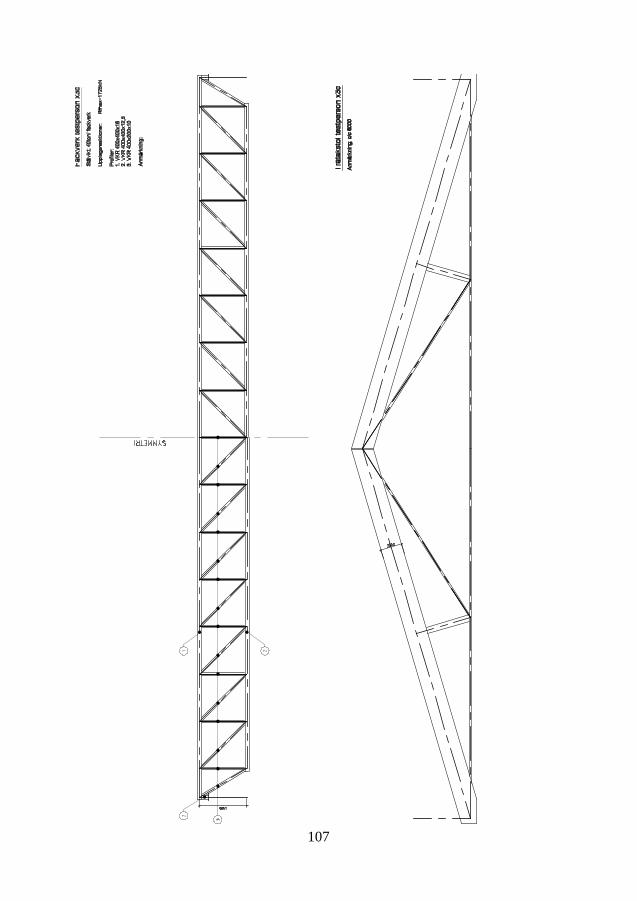
107

108

109
Appendix F
Hand calculation test 1Conditions - from Paper I
109

110
Input - design loads STR 6.10a
g1 37.4kNm
g2 26.8kNm
g3 6.8kN
m22.75m 4 74.8
kNm
G1 37.2kN
G2 13.4kN
q1 3.9kNm
q2 6.9kNm
Calculations This calculation is based on the assumption that the wall will act as a monolit on spring supports. Hence, thedisplacement of the wall will be a vertical movement, dy, and a rotation dr. This is analogue with how e.g. thestresses of a beam section is calculated. Plane surfaces remain plane even when loaded.
For a wall on three symmetrical and equally stiff spring supports and with symmetrical load, this would mean thatdr=0. This is analogue with a beam section with only axial load. This in turn means that a wall on symmetricallyplaced spring supports, but with an assymetrical load, as in the present case, may be considerred as a beamsection with both axial load and moment. The moment, M, acting on the cross section may be expressed as theaxial load, Qtot, times the excentricity of the load, eQ.
For the present problem the excentricity, e, will be defined as the distance from the loads center of gravity to theequivalent center of the supports, which in this case coincides with the middle support C. This is calculated asfollows:
Sum of loads:
Qtot g1 4g2 q1 4q2 11.8m g3 9.6m 4G1 4G2 2.998 103 kN
eQ
g1 4g2 q1 4q2 11.8m11.8m
24.8m g3 9.6m 0 4G1 4.8m 4G2 7m
Qtot0.649m
The "axial" load, Qtot will be evenly distributed over the supports B, C and D as they have the same springstiffness, E*A/l.
110

111
RQQtot
39.995 105 N
The excentricity moment, M, will be balanced by a couple of opposite forces +/-RM:
M Qtot eQ 1.947 103 kN m
RMM
2 4.8m2.028 105 N
The reaction forces of each support will be:
RB RQ RM 1.202 106 N
RC RQ 9.995 105 N
RD RQ RM 7.967 105 N
The percentual distribution will be as follows:
δBRBQtot
40.096 %
δCRCQtot
33.333 %
δDRDQtot
26.57 %
111

112
By comparing this to the result of the FE-calculation for "real response" we see that this simple calculationcorresponds very well:
The deviation from the "correct" value for each column position will be:
ErrorBRB
1155kN1 4.093 %
ErrorCRC
1028kN1 2.774 %
ErrorDRD
788kN1 1.104 %
Also the percentual distribution follows very well.
112

113
Appendix G Results and quotations from interviews, the number of participants who has mentioned the same issue or argument within brackets (xx), if more than one.
Tidiga skeden 1. Behov av duktig arkitekt och väl genomarbetat underlag (3) 2. Viktigt att det man gör anpassas till produktionen (2) 3. Det är i tidiga skeden man kan påverka mest – det blir dyrare senare. (2) 4. Även installationer behöver hanteras tidigt 5. Personen är van vid att jobba i tidiga skeden 6. Det är ibland svårt att se igenom vad som är viktigt för arkitekten 7. Vill få tydliga uppgifter serverade – gilla läget och lösa uppgiften 8. Det stabiliserande systemet är en av de viktigaste bitarna. (2) 9. Det är viktigt att diskutera med arkitekten för att hitta en bättre lösning (2) 10. Det är bäst om man kan hålla sig inom ramarna som ges i
arkitektunderlaget – minskar risken för fel och samordningsmissar (speciellt för prefabprojekt).
11. Vill gärna jobba i sena skeden. 12. Krävs mycket erfarenhet för att jobba i tidiga skeden – minst 10år 13. Entreprenören är mer öppen för ändringar än arkitekten om det finns
möjlighet till besparing 14. Ingen är intresserad av en ändring som inte innebär besparing 15. Brukar vara någon av cheferna som jobbar i tidiga skeden 16. Det finns tumregler för att bestämma avstånd mellan bärande väggar etc. 17. Entreprenören betalar oftast inte för en djupare analys i tidiga skeden utan
det är bättre att förenkla systemet istället. 18. Jobbar man åt en entreprenör blir den arkitektoniska intentionen sekundär. 19. Vill ha ett så enkelt stomsystem som möjligt för att slippa problem och
risker. 20. K kommer ofta in sist i det tidiga skedet 21. Ofta blir man bara ombedd att lösa uppgiften och se till så att det håller. 22. Gäller det stora vikter, spännvidder eller krafter har man ingen känsla
längre 23. Önskar arbetssprocess som på brosidan – checklistor etc. 24. Det är viktigt att få kvitto på att man gjort rätt – speciellt som ung 25. Skriver ihop ett dokument med förutsättningar i det tidiga skedet 26. Vill ha gott om tid att pröva olika lösningar i tidigt skede 27. Det går snabbare och snabbare i processen – bygget påbörjas innan man
tänkt klart 28. Hans bidrag brukar uppfattas som positivt 29. Det är i de tidiga skedena man vill vara med och jobba 30. Jobba med de stora dragen – hitta systemet och utvärdera byggmetoder 31. Man är sällan först in som konstruktör i ett projekt – Arkitekten först oftast 32. Om det gäller ett FFU till TE kan TE:s konstruktör ändra fritt – det rör sig
mer om ett underlag för upphandling.
113

114
33. Uppdagas ett statiskt problem i bygghandlingsskedet blir svaret från beställaren ofta ”det får ni lösa”
34. Man ska hitta en lösning som passar beställaren 35. Man måste identifiera vilka parametrar som är viktiga för arkitekten 36. Hitta ett system som passar 37. I komplexa projekt (t ex) sjukhus liknar systemskedet
bygghandlingsskedet ganska mycket. 38. Viktigt att försöka se vad det ska bli 39. Tidiga skeden är ofta ganska sena 40. Man känner sig ibland som en ”bromskloss” 41. K-sidan betraktas ibland bara som nåt som måste göras 42. Det faktum att det sällan sker ras har lett till att många utgår ifrån
(jargong) att vi har ”både hängslen och livrem” 43. Det finns ibland en intressekonflikt mellan arkitektens visioner och
byggnadens krav Testet Test 1 1. Kommentarer som ”skrämmande”, ”oroväckande”, ”sensationell
spridning”, ”väldigt intressant”, när resultatet presenterades. (10) 2. Kommenterar lastfördelning som orsak till spridning (4) 3. Tror att en anledning till spridning är om man använt BKR eller Eurokod
(6) 4. Tror att en anledning är att vi ”jobbar olika” (2) 5. Man utrycker att man känner sig trygg med sin lösning ”Jag tror jag har
rätt” 6. Försvar av ”byggmek-balken”, dvs modell med vek balk på styva stöd. 7. Ser sig som konservativ och vill räkna förhand 8. Lättare att förstå handberäkningar 9. ”Man måste veta vad man sysslar med” 10. Personen förstår inte att den gjort fel 11. Bra att kombinera det stabiliserande och det bärande systemet 12. Det är för stor skillnad mellan resultaten i undersökningen 13. Skillnaden kan bero på modellen eller lastvärdena 14. Lastfördelningen är framtagen procentuellt genom modellering av balk i
ramanalys [vek balk på styva stöd] 15. Oro över hur branschen ska emot resultatet ifrån studien. 16. Betraktade förutsättningarna som givna i uppgiften – ville inte lägga till
stabvägg i tvärled 17. ”Jag måste rätta in mig – inte ifrågasätta” 18. Tror det blir spridning till följd av att vissa använt FE-program och andra
räknat för hand. 19. ”Det är lätt att göra fel” 20. Räknar med fördelningen 50%-125%-50% – ”får lite extra last – det känns
tryggast” 21. Räknar ofta både med dator och för hand. Om de överensstämmer har man
rätt. 22. Prefab eller ”sammanplockkonstruktioner” ska skicka krafter till varandra
- det är en risk
114

115
23. Entreprenören vill gärna ha enkelhet istället för optimering. 24. Har gjort analyser i FE-programmet som han inte förstår och kan redogöra
för. 25. Upplever ingen större skillnad mellan Eurokod och BKR 26. ”En del kollegor fortsätter räkna enl BKR trots att de inte får” 27. ”Ingen alfa-reduktion i tidigt skede”, menar att möjligheten till
lastreduktion pga belastad yta inte används. 28. Bra att göra två olika beräkningar för att bedöma rimligheten om man
löser en sorts uppgift för första gången. 29. Gjorde först en handberäkning som kontrollerades med en FE-beräkning 30. ”Man kan lätt låsa sig om man bara använt FE-program – speciellt som
ung” 31. Man måste börja från grunden med handberäkningar 32. ”Brukar räkna 50-50 fördelning i tidiga skeden”, dvs en väldigt förenklad
modell av lastfördelningen som inte tar hänsyn till inpänningsförhållanden.
33. ”Stabiliteten kan betraktas på olika sätt” 34. Är skolad i handberäkningar men ser möjligheterna med FEM 35. Yngre konstruktör som kör FE-beräkningar får ofta inte med alla aspekter
– missar helheten 36. Yngre konstruktörer tror att FEM ger det rätta svaret 37. Det är viktigt att ifrågasätta svaret ifrån FE-beräkningar 38. FE-beräkningar tar mer tid initialt – det är inte säkert man får betalt för
detta 39. Anser inte att spridningen är så alarmerande med tanke på alla osäkerheter 40. FEM-programmet upplevdes som ypperligt för detta problem eftersom det
hanterar stabiliteten också. 41. FE-programmet överskattar styvheten i tvärled genom att beakta
ramverkan. 42. ”De 3-4-5 första åren av karriären bör man endast räkna för hand eller med
enkla program”. 43. Anledning till spridning kan vara lastreduktionsfaktorer på nyttig last (jmf
27) 44. ”Bättre att ligga för högt än för lågt i tidigt skede” 45. Det krävs att man tydligt ställer upp sina förutsättningar för att kunna ge
ett jämförbart svar Test 2 1. Personen förstår inte att den gjort fel (2) 2. Menar att resultatet inte borde skilja så mycket i denna uppgift 3. ”Det är lätt att göra fel” 4. Lätt att grotta ner sig och tappa överblicken och känslan för rimlighet 5. Eurokod är inte så svår 6. Eurokod tar tid att lära sig 7. ”Man utnyttjar sin erfarenhet mer och mer ju äldre man blir” 8. Man behöver vara specialist på trä för att kunna lösa detta problem med
trä. 9. Farligt att ta fram en lösning för något man inte behärskar. 10. Indelningen av vertikaler viktig för optimering
115

116
11. ”Det är farligt med trä” 12. Dimensionerar helst inte fackverk - inte så duktiga på det [deras företag] 13. När man dimensionerar ett vanligt husprojekt känner man sig mer trygg än
när det är en ny problemställning som fackverket. 14. Inte rädd för att fråga kollegor, prestigelös 15. ”Ju längre man jobbar desto mer förstår man hur svårt det man sysslar med
är”. 16. Tog i lite på egenvikten till taket eftersom den uppgiften var osäker 17. ”Svårt att ta fram en optimal lösning – blir lätt massor med förslag” 18. Saknades tid för optimering 19. Olika erfarenhet leder till olika lösningar 20. Trodde att höjden på takkonstruktionen var given 21. Inte lika många val på lasterna borde ge mindre spridning 22. I ett förstaläge är det bättre att ha med några ton till. Värre att lägga på
senare 23. Det gäller att ha en tät dialog med entreprenören som gör kalkyl för att inte
lägga på säkerhetsmarginal dubbelt. Kommunikation och tydlighet 24. Beroende på hur mycket man vet och hur mycket tid man har behöver man
lägga på olika mycket säkerhetsmarginal 25. Det är lärorikt att ha en tät dialog med en erfaren kalkylator – de vet vad
som ska finnas med normalt sett. 26. Denna uppgift skulle han normalt sett lägga ner mer tid på innan han
skickade ut. 27. Takstolen han ritat ”skulle man kunna producera” Beräkningar 1. Personen kan inte redogöra för vad den gjort – svamlar 2. Gör alltid handberäkningar 3. Kontrollerar beräkningar med datorn 4. Stor skillnad mellan handberäkning och FE-beräkning för en hel byggnad
– ”aldrig samma” 5. Ändras något måste FE-beräkningen köras på nytt 6. ”Räknar du förhand har du säkerhetsmarginal i varje moment” 7. Olämpligt att göra FE-analys för prefabbyggnader 8. Lätt att invaggas i säkerhet när ”datorn säger att det funkar” 9. Viktigt att förstå hur byggnaden fungerar utan datorhjälp 10. Ser sig själv som konservativ och försiktig – det är bra att ha lite reserv
speciellt i tidiga skeden. 11. ”Materialleverantörer som dimensionerar lägger sig gärna på 99%” - dvs
ingen marginal 12. Upplever Eurokod som opedagogiskt skriven och svår att hitta i. 13. Gör ofta flera beräkningar för att kontrollera rimligheten 14. Stomanalysen görs förhand medan detaljdimensioneringen görs med
datorstöd 15. Komplicerade geometrier är lämpliga att analysera med datorstöd 16. Hur man väljer att jobba – för hand eller med dator - är väldigt individuellt 17. Övergången till Eurokod har gått bra men vissa beräkningsprogram saknas 18. Det är oftast de yngre som kör de tunga och avancerade beräkningarna
idag.
116

117
19. Beräkningsprogrammen (ramprogram t ex) har fördelen att man slipper räkna om allting om det sker en geometrisk förändring.
20. ”Det är oftast inte FEM-programmet i sig som gör fel utan kvaliteten beror på handhavandet och kunskapen hos den som använder programmet”.
21. ”Det krävs erfarenhet för att kunna ifrågasätta resultat ifrån beräkningsprogram”.
22. Det är svårt att felsöka beräkningsfiler. 23. Även FEM-användaren skapar sig erfarenhet som används för att
ifrågasätta resultat ifrån andra beräkningar. Men det kräver mycket av användaren
24. Vill ha beräkningsgången och resonemanget på papper – kompletterar med andra beräkningar.
25. När man var yngre ville man göra allt med dator 26. Ju mer man jobbar som handläggare desto mindre tid finns över för att
göra beräkningar. 27. Oftast nyutexaminerade civilingenjörer som gör beräkningar. 28. Använder fortfarande BKR även om han helst inte berättar det 29. Generellt omständligare med Eurokod 30. Gör mycket överslag i sitt arbete – även med datorverktyg 31. Gör ofta flera beräkningar för att ”gaffla in sig” 32. Han menar att det behövs mer granskning 33. Det är väldigt individuellt hur man väljer att redovisa sina beräkningar 34. Man måste förklara vad man gör – det vi gör är till stor del en pedagogisk
uppgift i tidiga skeden Granskning 1. Granskning sker genom egenkontroll, (checklistor) (7) 2. Ritningar granskas (10) 3. Använder sig av bollplank utanför projektet (2) 4. Kontrollplan fylls i – rutiner finns för granskning (4) 5. Beräkningar granskas med egenkontroll (6) 6. Konstruktörens erfarenhet är viktig 7. Kontrollsystem efterlevs inte (3) 8. Ofta tidspress i projekten (2) 9. Viktigt att planera för granskning (4) 10. Kommunikation och tydlighet är viktig (2) 11. Kommunikation med de som ska producera är viktig (se pkt 2 Tidiga
skeden) (3) 12. Viktigt med rutiner, metodiskt arbetssätt (2) 13. Det finns risk att saker faller mellan stolar när många aktörer är inblandade 14. Huvudkonstruktör kontrollerar helheten. 15. Ibland ritar man som allmänkonstruktör bara grunden men ska granska
övriga delar. 16. Stomleverantören vill ofta ändra på bärningsprinciper som slagits fast i
systemskedet vilket leder till risk för fel. 17. Beräkningar lagras digitalt 18. Brister i dokumentation beror på hårt pressade priser (2) 19. Förr redovisades beräkningar för byggnadsnämnden (2) 20. Det var bättre förr – granskning av byggnadsnämnden (3)
117
118
21. Det blir mindre fel om man tvingas ställa samman sitt resultat. 22. Erfarenhetsåterföringen kan bli bättre (2) 23. Granskar beräkning med nytt datorprogram för hand 24. Snabba ändringar kräver extra försiktighet 25. Viktigt att använda en så flexibel lösning som möjligt så att en liten
ändring kan tas upp 26. Positiv till eurokod – beskriver bättre hur man ska göra. 27. Varje projekt bör ha ett dokument med beräkningsförutsättningar 28. Problem med att beräkningsprogram har olika teckenregler 29. Utför rimlighetskontroll av dimensioner, yngre kollegors resultat
kontrollberäknas överslagsmässigt (3) 30. Granskning utelämnas vid tidspress (3) 31. Individberoende hur mycket tid som läggs på granskning 32. Tid för projektering innan byggstart för snål. 33. Totalentreprenader speciellt utsatta för korta projekteringstider. 34. Entreprenören är en viktig del i erfarenhetsåterföringen 35. Riktlinjer för dokumentation av beräkningar saknas 36. Det är den enskilde ingenjörens eget ansvar att dokumentera det den gör
korrekt. (2) 37. Vill bli bättre på att dokumentera beräkningar etc 38. Spårbarhet mellan handberäkning och datorberäkning saknas 39. Använder gamla projekt för att jämföra mot 40. ”Om man inte anstränger sig själv utan bara använder andras erfarenhet
utvecklar man inte sin egen förmåga som konstruktör”. 41. Man måste ha en känsla för vad som är bra för att kunna föreslå ändringar 42. Äldre kollegors arbete granskas inte lika noggrant (2) 43. Önskar att det skedde extern granskning från ett annat företag (2) 44. Jämför med hur det går till på brosidan 45. Extern granskning skulle leda till kunskapsåterföring i branschen 46. Beräkningar granskas inte (4) 47. Erfarenhetsåterföring sker bara inom små grupper 48. Grova missar fångas genom ritningsgranskning innan utskick 49. Projekteringen pågår ofta samtidigt som man bygger. 50. Korta projekteringstider äventyrar kvaliteten 51. Önskar att samhället ställde krav på granskning 52. Det finns inte tid att förbättra en dålig lösning 53. Granskningen beror mycket på vilken som är uppdragsansvarig 54. Ingenjörens ansvar att det som räknas granskas 55. Kontrollplanen tillför ingen kvalitet – bara för att uppfylla
kvalitetssystemet 56. Det är frågan om företagsledningen egentligen vet hur det går till i arbetet
med kvalitetssystemet 57. Om riskerna inte försvinner är det inget bra kvalitetssystem 58. Kvalitetssystemet måste tillföra något till kvaliteten – annars använder
man det inte 59. Ingen kund klagar på att det tar en dag extra för att granska handlingarna. 60. Sammanfattar beräkningar i beräkningsrapport ”då tänker man igenom det
och ser så att man fått med allting” 61. Mycket diskussion om beräkningar inom gruppen
118

119
62. Tidigt i projektet sätter sig ett antal erfarna för att diskutera den aktuella problematiken och ställer samman konstruktionsförutsättningar
63. ”Det ligger på individen att begära granskning” 64. Önskar att företaget såg till att beräkningar granskas 65. ”Granskas inte beräkningarna kan någon göra ett jobb som den inte
förstår” 66. ”Kunden förstår inte om beräkningarna är rätt eller fel” 67. Företaget har ett generellt system för dokumentation 68. Man måste trycka på för att få till granskning av beräkningar ”här vill jag
att någon ska granska” (jmf pkt 63) 69. Om man får till granskning så blir det oftast i form av diskussion med
”bollplank” 70. Önskar motsvarande system för granskning av beräkningar som finns och
fungerar för ritningar 71. I ett nytt projekt tas en handläggare in som gjort ett liknande projekt vid
startmötet 72. Det är svårt att beskriva hur en beräkning ska ställas upp när det rör
allmänkonstruktion – problemen är så olika. 73. Om det är någon som kommer direkt från skolan så granskas
beräkningarna 74. Erfarenheten hittar många fel utan regelrätt granskning 75. Olika kunder ställer olika krav på granskning 76. Alla företag har kvalitetssystem 77. Kvaliteten varierar mycket inom företag och mellan företag 78. ”Alla kvalitetssystem jag sett hittills handlar bara om hur man skyfflar
papper – de granskar inte tekniken”. 79. ”Egenkontroll kräver att man förstår allt man ska bocka i – mäter oftast
bara att man gjort ett moment – inte om det man gjort är rätt”. 80. ”Det behövs ett system för granskning av beräkningar där den som
granskar har tillräcklig erfarenhet.” 81. ”Det går att hitta fel i alla beräkningar – oavsett hur noggrann man varit.” 82. ”Förståelsen för det statiska systemet är viktigare än hur det enskilda
elementet beräknas.” 83. ”Det lättaste sättet att komma runt ett problem är att aldrig inse det” 84. ”En optimal lösning för kunden behöver inte vara en optimal
konstruktionslösning” 85. I FFU beskriver han ganska detaljerat hur byggnaden ska fungera och att
det sedan är entreprenörens ansvar att det blir så. 86. ”Det gäller att ha koll på helheten för att inte saker ska falla mellan
stolarna” 87. ”Beställaren har ett ansvar att veta vad han köper - speciellt viktigt i
delade entreprenader.” 88. ”Den enskilde konstruktören har ett stort ansvar” 89. Kvalitetssystemet är ofta bara en ”pappersgrej” 90. Kvalitetssystemet är tidskrävande att uppfylla samtidigt som det inte höjer
kvaliteten 91. Det är fördyrande med extern granskning 92. ”Man måste skriva och förklara vad man gör i sina beräkningar” 93. Problem med att äldre beräkningsfiler inte går att läsa i ny programvara.
119

120
94. Deras avdelning har en öppen och prestigelös kultur som gynnar erfarenhetsåterföring
95. Han känner idag stor tillfredsställelse över att kunna sitt yrke 96. Man kan tappa kreativitet om man arbetar efter mallar och checklistor 97. Om man bara jobbar utifrån mallar stöter man förr eller senare på ett
problem som mallen inte är lämpad för. Ras 1. Känner oro och är upprörd pga byggnader som rasat (4) 2. Det är problem med uppstyckat ansvar. (se även pkt 13. Granskning ) 3. Menar att den undersökning jag gör är aktuell 4. Konstruktörer känner ofta en ständig oro för ras och liknande. (4) 5. Helhetsförståelse är det viktigaste för att en byggnad ska bli säker (2) 6. Byggnader är komplexa system 7. Granskning blir viktigare och viktigare 8. ”Det sker saker på arbetsplatserna – det utförs ofta inte enligt handling”
(2) 9. ”Liten risk för ras eftersom säkerhetsmarginalerna är stora.” (2) 10. Enligt ryktet skulle Ystadraset bero på felaktig montageordning [behov av
information] 11. Grubblat på det som hände i Ystad – undrar vad man (haverikommisionen,
authors remark) kommer fram till. 12. ”Det vi konstruktörer gör är viktigt” 13. Tror inte certifiering av konstruktörer skulle hjälpa 14. Tror inte på myndighet som granskar K-ritningar skulle hjälpa 15. Skador eller ras i byggbranschen tystas oftast ner 16. Vaknar mitt i natten – sover dåligt periodvis (3) 17. ”Det är så lätt att göra fel.” 18. ”Gör jag fel så kan folk dö” 19. ”Märklig bransch – allting stressas fram – fort och billigt” 20. ”Extern granskning skulle dra ner tempot” 21. Tvingas av tidsbrist välja den första lösningen han kommer på 22. Att pressa priset på konstruktören är att ”förhandla om säkerheten” 23. Har funderat på att byta jobb 24. Det är viktigt att rekrytera rätt person som konstruktör. 25. Om man inte har helhetsgreppet så riskerar ibland saker att falla mellan
stolarna 26. I delade entreprenader är det ofta otydligt vem som har ansvaret för
helheten (2) 27. Beställaren bör ha en konstruktör kopplad direkt till sig 28. Det saknas en generation konstruktörer (mellan 40-50år) vilket leder till
att man som väldigt ung nu flyttas upp som UA eller ansvarig konstruktör 29. Det behövs en granskningskultur i branschen 30. Konstigt att man får bygga höga hus som inte granskas av tredje part. 31. Konstruktören måste stå på sig och säga ifrån ”jag kan inte lösa detta med
dessa resurser och den tidplanen” 32. ”Stabiliteten är det viktigaste att ha koll på.” 33. Det gäller att förstå systemet – speciellt vid ombyggnad där kanske
dokumentationen är dålig eller ofullständig.
120

121
34. Man måste lägga på större marginal på det man gör i projekt med stora osäkerheter
35. Hans företag råkade ut för ett ras för några år sedan pga att smidesfirman ändrat en infästning
36. Även i utförandeledet går det snabbt 37. Det värsta är medvetet fuskande – av kostnadsskäl 38. Entreprenören utnyttjar ibland att det finns stora marginaler i
dimensioneringsreglerna 39. Upplevde stor oro när han var yngre 40. Det händer att man kommer ut på arbetsplatsen och ser att det inte alls ser
ut som man tänkt sig. 41. Det är viktigare att tänka hela varvet runt än att få mer tid – ”kan du inte
något spelar det ingen roll om du får en eller tre dagar på dig” 42. Man bygger ofta samtidigt som man projekterar – stor risk 43. Ett bra och genomtänkt A-underlag minskar risken om tempot är högt.
121