Embed Size (px)
Citation preview
The HKIE Structural Examination – Written Examination 2015
Section 2: Design Questions
(80% of the Written Examination)
Date: 26 November 2015 (Thursday)
Time: 12:00 nn - 06:00 pm
Answer ONE question only
Question 1 An Observation Tower
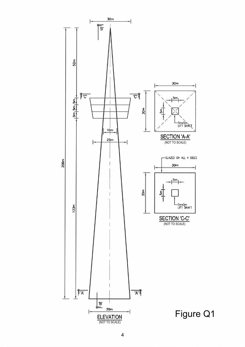
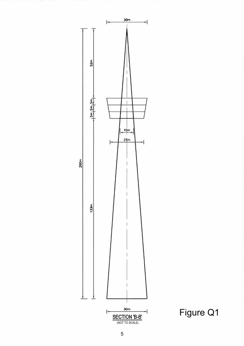
Client’s Requirements The following client's requirements must be met: 1. A 200m high Observation Tower (the Tower) is proposed near the Victoria
Harbour as shown in Figure Q1. 2. The on plan base dimensions of the Tower are 30m by 30m. In the middle of the
Tower, a space of 5m by 5m is designated for the construction of 4 passenger lifts.
3. At 133m a glass enclosed three storey visitor/eatery block is built to allow
visitors/diners to have a clear view of the Harbour. 4. The enclosed visitor/eatery block should have the following dimensions: 30m at
the top; 25m at the base and a storey height of 5m. 5. The top of the foundations should be at least 3m below the ground surface. This
is to avoid interfering with existing utility services within the site. 6. A minimum 2‐hour fire resistance rating is required for all elements of
construction for the Tower.
Imposed Loads (on the visitor/eatery block) 7. Roof 5 kN/m2
Intermediate floors 5 kN/m2
Site Conditions 8. The site is flat and is located near the sea front. The wind loads shall be in
accordance with the current Hong Kong Wind Code.
1
Ground Conditions 9. Ground conditions as revealed by the ground investigation boreholes are:‐
Ground water is found at 1.5m below the existing ground level. From the ground level to a depth of 5m – very loose and compressible Fill, N values range from 2 to 4. From 5m to 8m – Alluvium in the form of medium dense silty sands, N values range from 12 to 20. From 8m to 12m – Soft dark marine clay, N values range from 2 to 4. From 12m to 30m – Completely decomposed tuff in the form of dense to very dense silty sands, N values range from 50 to 180. From 30m onwards – Moderately decomposed (Grade III) tuff with total core recovery greater than 85%.
Omit from Consideration 10. Design of glass façade. 11. Lift shaft.
2
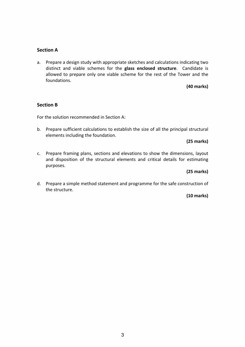
Section A a. Prepare a design study with appropriate sketches and calculations indicating two
distinct and viable schemes for the glass enclosed structure. Candidate is allowed to prepare only one viable scheme for the rest of the Tower and the foundations.
(40 marks)
Section B For the solution recommended in Section A: b. Prepare sufficient calculations to establish the size of all the principal structural
elements including the foundation. (25 marks)
c. Prepare framing plans, sections and elevations to show the dimensions, layout
and disposition of the structural elements and critical details for estimating purposes.
(25 marks) d. Prepare a simple method statement and programme for the safe construction of
the structure. (10 marks)
3
(NOT TO SCALE)
(NOT TO SCALE)
(NOT TO SCALE)
Figure Q1
4
(NOT TO SCALE)
Figure Q1
5
Question 2 Sports Hall
Client’s Requirements The following client’s requirements must be met: 1. A new sports hall is to be built in a new town park in Hong Kong to provide
sports facilities for the residents, on a fast track programme. 2. The sports hall is to accommodate four badminton courts which, if required, can
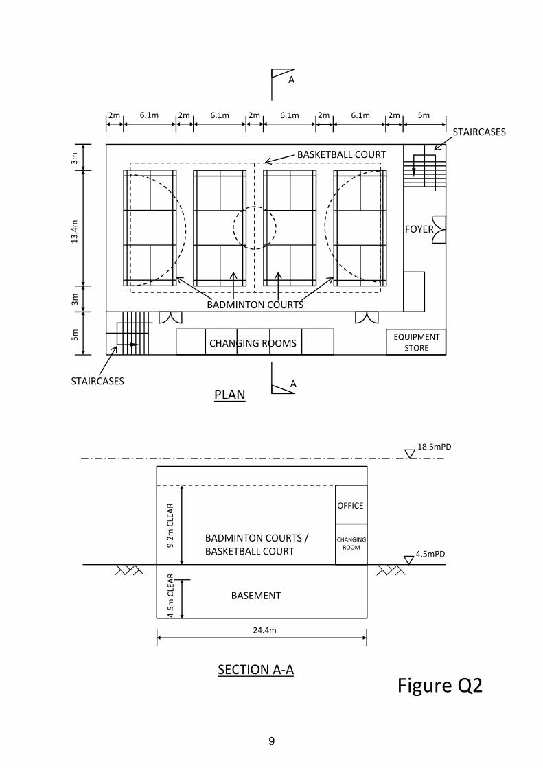
be converted to a basketball court. 3. Each badminton court measures 6.1m x 13.4m on plan, with a minimum of 2m
clear space surrounding all the outer lines of the courts, including a space of 2m between any two courts. A clear height of 9.2m is required.
4. The badminton courts can be converted to a basketball court when required,
which has a plan dimension of 29m x 15m, with a maximum clear height of 9.0m. A 2m clear space is also required around the court.
5. A 5m strip of space is to be provided along one of perimeters of the hall for
changing rooms, equipment store and other auxiliary facilities. Offices will be on top of these spaces. No vertical elements are allowed within this strip and the space around the badminton/basketball courts.
6. A one level of basement is provided for lockers, back of house facilities and
other building services equipment, having a clear headroom of 4.5m. 7. The foyer and refreshments booths are provided at the entrance. 8. The exterior wall will be built of concrete or brick, with window at the higher
level to provide natural lighting. Vertical elements protruding beyond the court space are allowed.
9. There is currently no requirement for overhead loadings within the hall. 10. The required clear width and height of the sports hall is shown on Figure Q2. 11. The ground floor is at 4.5 mPD. There is a height restriction of 18.5 mPD on this
site.
6
12. The following finishes/services requirements will apply:
Floor Finishes Building Services Zone ‐ Ground Wood floor on 50mm screeding 1.2m ‐ Basement Hardener 0.6m ‐ Roof 300mm thick waterproofing
Imposed Loads 13. The imposed loads should be in accordance with the current Hong Kong Code of
Practice for Dead and Imposed Loads.
Wind Loads 14. The wind loads shall be in accordance with the current Hong Kong Wind Code.
Site Conditions 15. Ground conditions:
Ground level – 3.0m Loose Fill 3 m – 10 m Sand/gravel, SPT N‐value = 25 Below 10 m Bedrock Ground water is found at 2.0m below the existing ground level.
Omit from Consideration 16. Design of staircases, changing rooms and offices.
7
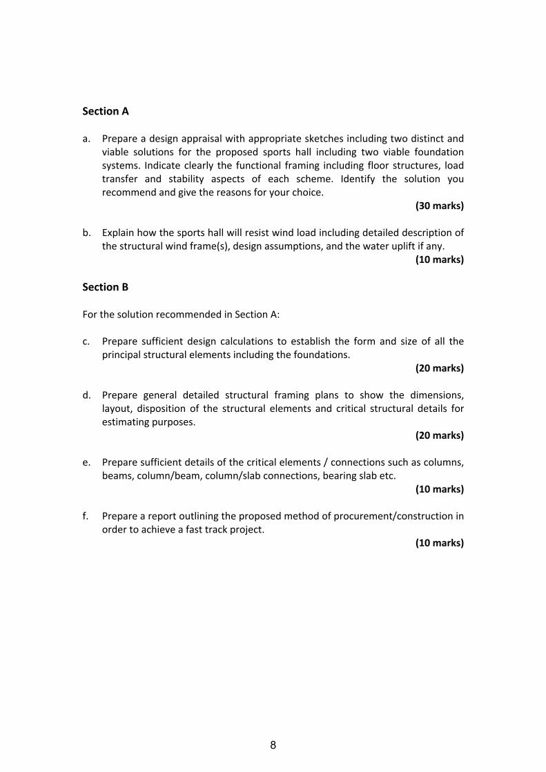
Section A a. Prepare a design appraisal with appropriate sketches including two distinct and
viable solutions for the proposed sports hall including two viable foundation systems. Indicate clearly the functional framing including floor structures, load transfer and stability aspects of each scheme. Identify the solution you recommend and give the reasons for your choice.
(30 marks) b. Explain how the sports hall will resist wind load including detailed description of
the structural wind frame(s), design assumptions, and the water uplift if any. (10 marks)
Section B For the solution recommended in Section A: c. Prepare sufficient design calculations to establish the form and size of all the
principal structural elements including the foundations. (20 marks)
d. Prepare general detailed structural framing plans to show the dimensions,
layout, disposition of the structural elements and critical structural details for estimating purposes.
(20 marks) e. Prepare sufficient details of the critical elements / connections such as columns,
beams, column/beam, column/slab connections, bearing slab etc. (10 marks)
f. Prepare a report outlining the proposed method of procurement/construction in
order to achieve a fast track project. (10 marks)
8
FOYER
CHANGING ROOMS
STAIRCASES
STAIRCASES
BADMINTON COURTS
EQUIPMENT STORE
5m 2m 2m2m2m 2m 6.1m 6.1m 6.1m 6.1m
3m
3m
5m
13.4m
BASKETBALL COURT
A
APLAN
SECTION A‐AFigure Q2
24.4m
4.5m CLEAR
9.2m CLEAR
4.5mPD
18.5mPD
OFFICE
CHANGING ROOM
BASEMENT
BADMINTON COURTS / BASKETBALL COURT
9
Question 3 Office Building
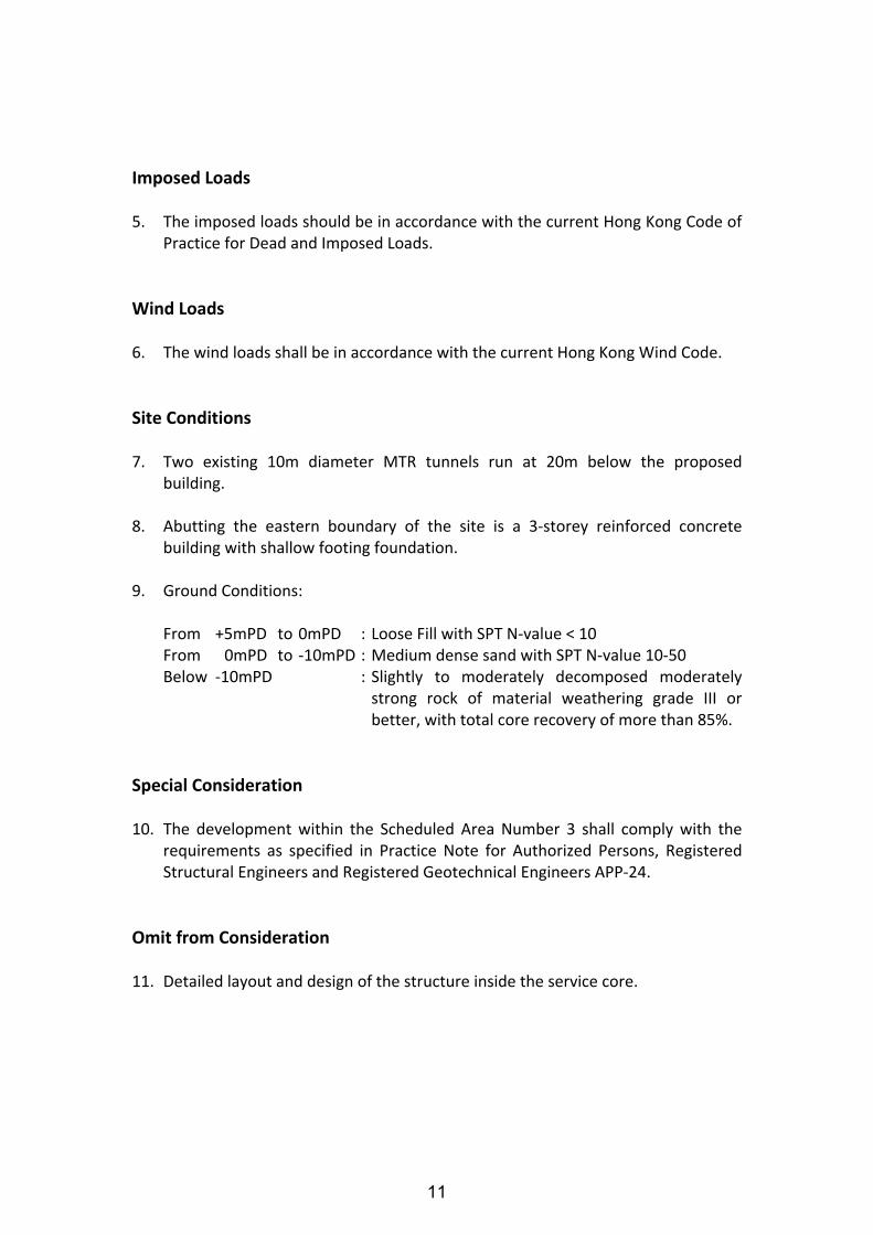
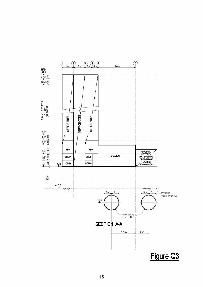
Client’s Requirements The following client’s requirements must be met: 1. An office building is proposed within Scheduled Area Number 3 as defined in the
Buildings Ordinance. See Figure Q3. 2. The proposed use of office building with the minimum headroom requirements
and fire resistance rating is listed as follows:
Floor Mark Usage Minimum Clear Headroom* (m)
Fire Resistance Rating
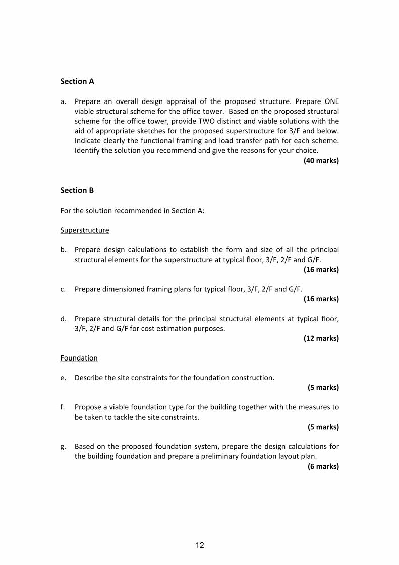
3/F – 27/F (Typical floor)
Office 2.5
1 hour
2/F E&M rooms 2.5
1/F Shop 3.5
G/F Stadium
8 (From gridline 4 to 5)
11.5 (From gridline 5 to 6)
Lobby 3.5
* The minimum clear headroom is the floor height clear of all structures and building services. A service zone of minimum 300mm depth should be allowed for underneath all floors.
3. The restrictions on the location of vertical structural elements are as follows:
Floor Mark Area Restrictions
3/F – 27/F (Typical floor)
Office ‐ No internal columns permitted.
2/F E&M room ‐ No restriction.
1/F Shop ‐ No internal columns permitted.
G/F Lobby and stadium
‐ No internal columns permitted.
4. The main roof structure above office tower and flat roof structure above
stadium shall not be inverted.
10
Imposed Loads 5. The imposed loads should be in accordance with the current Hong Kong Code of
Practice for Dead and Imposed Loads.
Wind Loads 6. The wind loads shall be in accordance with the current Hong Kong Wind Code.
Site Conditions 7. Two existing 10m diameter MTR tunnels run at 20m below the proposed
building. 8. Abutting the eastern boundary of the site is a 3‐storey reinforced concrete
building with shallow footing foundation. 9. Ground Conditions:
From +5mPD to 0mPD : Loose Fill with SPT N‐value < 10 From 0mPD to ‐10mPD : Medium dense sand with SPT N‐value 10‐50 Below ‐10mPD : Slightly to moderately decomposed moderately
strong rock of material weathering grade III or better, with total core recovery of more than 85%.
Special Consideration 10. The development within the Scheduled Area Number 3 shall comply with the
requirements as specified in Practice Note for Authorized Persons, Registered Structural Engineers and Registered Geotechnical Engineers APP‐24.
Omit from Consideration 11. Detailed layout and design of the structure inside the service core.
11
Section A a. Prepare an overall design appraisal of the proposed structure. Prepare ONE
viable structural scheme for the office tower. Based on the proposed structural scheme for the office tower, provide TWO distinct and viable solutions with the aid of appropriate sketches for the proposed superstructure for 3/F and below. Indicate clearly the functional framing and load transfer path for each scheme. Identify the solution you recommend and give the reasons for your choice.
(40 marks)
Section B For the solution recommended in Section A: Superstructure b. Prepare design calculations to establish the form and size of all the principal
structural elements for the superstructure at typical floor, 3/F, 2/F and G/F. (16 marks)
c. Prepare dimensioned framing plans for typical floor, 3/F, 2/F and G/F.
(16 marks) d. Prepare structural details for the principal structural elements at typical floor,
3/F, 2/F and G/F for cost estimation purposes. (12 marks)
Foundation e. Describe the site constraints for the foundation construction.
(5 marks) f. Propose a viable foundation type for the building together with the measures to
be taken to tackle the site constraints. (5 marks)
g. Based on the proposed foundation system, prepare the design calculations for
the building foundation and prepare a preliminary foundation layout plan. (6 marks)
12
HKIE Structural Examination 2015 Chief Examiner : Ir C M WONG Question 3 – Office Building
4
Version 1.0 (Updated on 16 Sep 20
8m 8m 5m 4m 26m
4m
13m
24m
13m
13m
24m
13m
8m 8m 26m5m 4m
13
HKIE Structural Examination 2015 Chief Examiner : Ir C M WONG Question 3 – Office Building
5
Version 1.0 (Updated on 16 Sep 20
8m 8m 26m5m 4m
8m 8m 5m 4m 26m
13m
13m
24m
13m
24m
13m
14
HKIE Structural Examination 2015 Chief Examiner : Ir C M WONG Question 3 – Office Building
6
Version 1.0 (Updated on 16 Sep 20
Y
17 m 9 m
8m 8m 26m5m 4m
5m 5m 5m5m
15m
4.5m
4.5m
6m(5
/F T
O 25
/F)
=73.5
m3.5
m x 2
1 STO
REYS
3.5m
3.5m
3.5m
3.5m
15
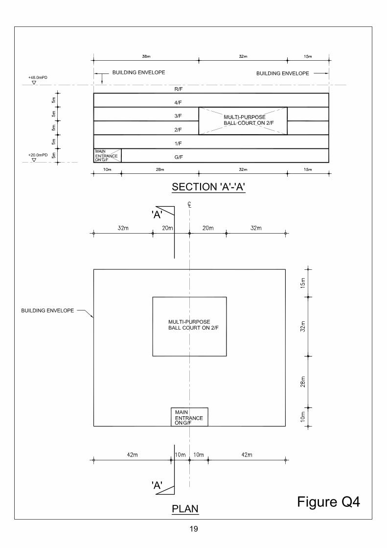
Question 4 Community Center
Client’s Requirements The following client’s requirements must be met: 1. A five storey community center, in an open site, is to be constructed in Tseung
Kwan O, NT. (See figure Q4). 2. No structure, including foundation, is permitted outside the building envelope. 3. Under the lease conditions, no structure can be built above +48mPD. 4. Minimum column spacing (center to center) is to be 12m. 5. No structure is allowed at the entrance lobby on the ground floor. 6. Minimum clear dimension of “multi‐purpose ball court or hall” on 2/F is to be
32m by 40m. 7. 250mm curtain wall is to be allowed at the perimeter of the building to allow for
natural lighting. 8. Minimum requirements on clear headroom (clear height of all structures,
finishes and building services) are as follows:
Floor Use Minimum Headroom (m)
Finishes & Services Zone (m)
G/F Entrance lobby and office 4.0 0.3 1/F Meeting rooms 4.0 0.3 2/F Multi‐purpose ball court or hall
Office 8.5 4.0
0.5 0.3
3/F Office 4.0 0.3 4/F Library 4.0 0.3 R/F Maintenance purpose (accessible) N/A N/A
9. A minimum 2‐hour fire resistance rating is required.
16
Imposed Loads 10. The imposed loads should be in accordance with the current Hong Kong Code of
Practice for Dead and Imposed Loads.
Wind Loads 11. The wind loads shall be in accordance with the current Hong Kong Wind Code.
Site Conditions 12. The site is located in Tseung Kwan O, NT at a datum level of about +20mPD. 13. Ground conditions are:
Ground level – 2m Fill, SPT N‐value less than 10 2m – 20m Alluvium, SPT N‐value = 100 20m – 40m Completely decomposed granite, SPT N‐value = 200 Below 40m Highly decomposed granite, SPT N‐value greater than 300 Ground water is encountered at 1.5m below ground level.
17
Section A a. Prepare a design appraisal with appropriate sketches including two distinct and
viable solutions for the proposed community center including two viable foundation systems. Indicate clearly the functional framing, load transfer and stability aspects of each scheme to meet all client’s requirements. Identify the solution you recommend and give the reasons for your choice.
(30 marks) b. Explain how the building structure will resist wind load including detailed
description of the structural wind loads and design assumption. Prepare a detailed wind load calculation for the proposed community center.
(10 marks)
Section B For the solution recommended in Section A: c. Prepare sufficient design calculations to establish the form and size of all the
principal structural elements including the foundation system. (20 marks)
d. Prepare general detailed structural framing plans to show the dimensions,
arrangement of the structural elements and details of all critical structural elements for estimating purposes.
(20 marks) e. Prepare a detailed method statement for the safe construction of the building
including excavation / lateral support and foundation works but excluding curtain wall installation.
(10 marks) f. Prepare a detailed construction program from commencement of foundation to
completion of structural works. (10 marks)
18
PD
PD
ON 2/F
ON
ON 2/F
ON
Figure Q4
19
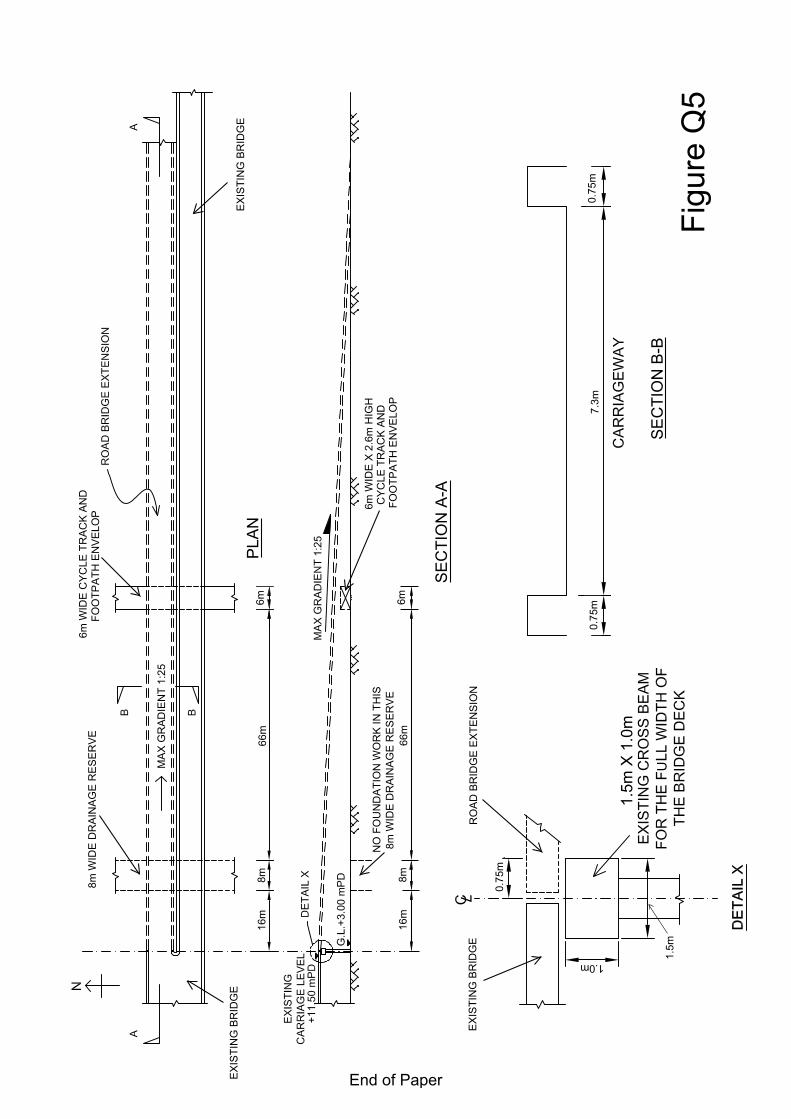
Question 5 Road Bridge Extension
Client’s Requirements The following client's requirements must be met: 1. As required by the traffic demand, a new road bridge extension from an existing
highway bridge is to be constructed over an existing park, cycle track and footpath in urban area as shown in Figure Q5.
2. The bridge extension will carry a two‐lane carriageway and the longitudinal
gradient of the new bridge deck shall not exceed 1:25 as required by the Transport Department.
3. The supporting point in the existing highway bridge has been designed with
sufficient strength to take up the future vertical loads from the new road bridge extension but not taking up any horizontal load as shown in Figure Q5.
4. No permanent or temporary work may be placed within the cycle track and
footpath envelops. Any permanent structure shall have at least 1m clearance to the cycle track and footpath envelops.
5. The structural form of the existing bridge is of beam and slab deck, therefore for
aesthetic reason, the structural form for the new road bridge extension shall not be of truss or cable supported type.
Imposed Loads 6. Vertical traffic loads UDL = 10.0 kN/m2
Invariable KEL = 120 kN per traffic lane Horizontal traffic loads 1500 kN, applied parallel to the carriageways
across the full width of the bridge deck
20
Site Conditions 7. The site is in the urban area. Basic wind speed is 46m/s based on a 3 second
gust; the equivalent mean hourly wind speed is 23m/s. 8. Ground conditions as revealed by boreholes are:
Ground level – 0.8m Made up ground 0.8m – 12.0m Soft clay with undrained shear strength, Cu = 40.0 kN/m2 Below 12.0m Moderately decomposed rock with allowable bearing
pressure = 3,000 kN/m2 Ground water was encountered at 2.8m below ground level.
Omit from Consideration 9. Design calculations for bridge parapet and bridge retaining walls.
21
Section A a. Prepare a design appraisal with appropriate sketches indicating two distinct and
viable schemes for the proposed bridge structure. The functioning framing, load transfer, safety and stability aspects of your schemes must be clearly indicated. Identify the solution you recommend and give the reasons for your choice.
(40 marks)
Section B For the solution recommended in Section A: b. Prepare sufficient design calculations to establish the form and size of all main
components including the bridge abutment and foundations. (25 marks)
c. Prepare general arrangement drawings including sufficient plans, elevations,
sections etc. for the bridge structure for quantity taking off purposes. (20 marks)
d. Prepare a simple method statement and programme for the safe construction of
the bridge. (15 marks)
22
EX
ISTI
NG
BR
IDG
E
16m
8m6m
66m
8m W
IDE
DR
AIN
AG
E R
ES
ER
VE
6m W
IDE
CY
CLE
TR
AC
K A
ND
FOO
TPA
TH E
NV
ELO
P
6m W
IDE
X 2
.6m
HIG
H
8m W
IDE
DR
AIN
AG
E R
ES
ER
VE
NO
FO
UN
DA
TIO
N W
OR
K IN
TH
ISC
YC
LE T
RA
CK
AN
DFO
OTP
ATH
EN
VE
LOP
6m66
m8m
16m
0.75
m0.
75m
7.3m
0.75
m
EX
ISTI
NG
BR
IDG
E
RO
AD
BR
IDG
E E
XTE
NS
ION
EX
ISTI
NG
BR
IDG
E
1.5m
X 1
.0m
U1.
5m
1.0mM
AX
GR
AD
IEN
T 1:
25
Figu
re Q
5
SE
CTI
ON
A-A
PLA
N
SE
CTI
ON
B-B
End of Paper

![Court Interpreter Written Examination: Overview Interpreter Oral Examination: Test Administration Standards [1] Court Interpreter Written Examination: Overview ... (the specific form](https://img.dokumen.tips/doc/110x75/5b497a207f8b9aa82c8b6312/court-interpreter-written-examination-overview-interpreter-oral-examination-test.jpg)