Embed Size (px)
Citation preview

THE HISTORY AND DEVELOPMENT OF A NEW SOHIC TEST
METHOD
C. Fowler
1 and J.M. Gray
2
1EXOVA Group, 182 Halesowen Road, Netherton, Dudley, West Midlands DY2 9PL, UK
2Microalloyed Steel Institute, 5100 Westheimer, Houston, Texas 77056, USA
Keywords: Sour Service, NACE, SOHIC, Test Methods, HAZ, Linepipe, Hardness,
HAZ Softening
Abstract
Stress Orientated Hydrogen Induced Cracking (SOHIC) has been the mechanistic cause of a
number of pipeline and pressure vessel failures, operating under sour service conditions. The
crack morphology is now recognized in NACE MR0175/ISO 15156 as being caused by an
independent mechanism. Within the Testing Appendix the standard says “other test methods
under development can be used,” such a method is now available. Previous test method NACE
TM0103, published by NACE, has now been withdrawn. This paper will follow the history of
SOHIC, the development of a new small-scale, short duration test method, and the possible
relationship with hardness and microstructure. Now that a true test method is available, the
mechanism of SOHIC can now be better studied and understood. Finally, the control of yield
strength and ferrite hardness by use of niobium will be considered.
Introduction
Stress Orientated Hydrogen Induced Cracking (SOHIC) was first reported in the early 1980s
during a testing program aimed at qualifying spiral welded linepipe for sour service [1]. It was
immediately recognized that residual stress played an important part in promoting the cracking
mechanism. From the early work a test method was developed and eventually published as
OTI95635 [2] by the UK Health and Safety Executive (HSE). This method was called the Full
Ring Test, and by its name the method was designed for linepipes, using a full section of linepipe
as the test piece.
Over the course of some years, an API sponsored project was undertaken and a test method was
eventually published by NACE International (TM0103) [3]. This method used what was termed
“double beam” samples. This method has subsequently been withdrawn at the instigation of the
original author. Thus a void in the testing armoury still exists.
A significant number of years ago, three organisations: Bodycote (now EXOVA), Force Institute
and TWI, joined forces in an attempt to design and validate a genuine SOHIC test method. After
7 years of work, a method has been defined that can be used on both pressure vessel plate and
linepipe (although the Full Ring Test is still favored for circumferentially welded pipe). This
work was followed up by a student from Aalen University undertaking his Bachelor Thesis on
the test development – Ulrich Pflanz [4].

Now that a test method is available, the study of the cracking mechanism can begin. In the
following sections, examples of SOHIC failures will be given, the new test method will be
described with early results, and further work will be proposed that will lead to the understanding
of this cracking mechanism. One such study has already been started and the first results will be
published at the NACE 2013 Conference in Orlando.
Background
SOHIC has been reported as the failure mode on at least 12 major pipelines, in addition,
numerous reports of SOHIC occurring in pressure vessels are in the literature. Reference [5]
contains some details of documented failures. Figure 1 illustrates a SOHIC pipeline failure.
Figure 2 illustrates a micrograph of a SOHIC crack.
Figure 1. SOHIC failure of spiral welded pipe, courtesy Shell Canada.

Figure 2. Microstructural features of SOHIC.
Generally the cracking is known to occur adjacent to a weld, however, one reported failure in
Germany was in seamless pipe [6]. Results from the early investigations indicated the
importance of residual stress, not only its magnitude, but also and probably more importantly, its
direction.
Figure 3 illustrates the residual stress effect in a large diameter linepipe. Besides overlap,
longitudinal displacement can be also observed.
Figure 3. Residual Stress, a “Critical Factor” – cut section of linepipe exhibiting displacement
due to residual stress.
ISO 15156/NACE MR0175 [7] and EFC 16 [8] attempt to account for the loss of residual stress
when a small sample is cut from a plate or pipe by increasing the load conditions. However, this
applied load is all in the same direction and does not reflect the true stress distribution. A tri-
axial stress is required to simulate the real conditions. Hence, some of the test methods cited in
the test standards will not show if a material is SOHIC susceptible or not.
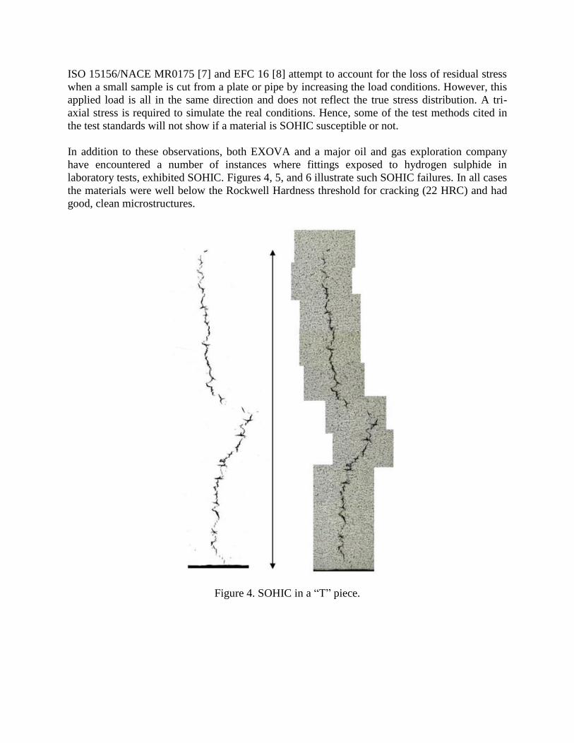
In addition to these observations, both EXOVA and a major oil and gas exploration company
have encountered a number of instances where fittings exposed to hydrogen sulphide in
laboratory tests, exhibited SOHIC. Figures 4, 5, and 6 illustrate such SOHIC failures. In all cases
the materials were well below the Rockwell Hardness threshold for cracking (22 HRC) and had
good, clean microstructures.
Figure 4. SOHIC in a “T” piece.

Figure 5. SOHIC in a dished end.
Figure 6. SOHIC in a reducer.

Thus the project aims were:
Small scale test method;
Short duration;
Definitive Go/No Go test criteria;
Reproducible.
Experimental
From the outset of this work, the complex stress distribution within linepipes and particularly
welded linepipes, was recognized. Some residual stress measurements have been performed,
however, they only provide the residual stress levels up to 1 mm from the surface. So, a more
direct approach was embarked upon.
The concept of ‘twist and bend’ was chosen, because when a spiral pipe is pressurized the weld
is effectively twisted, and as most failures have been in spiral pipe it was logical to start with this
assumption.
Several carbon steel materials were available, some known to be SOHIC resistant and some with
known susceptibility.
In outline, an extended four point bend sample was chosen that could also have a small degree of
twist imparted.
The design of a suitably useable rig was the most challenging part of this work; several designs
were built and discarded prior to the eventual final approved design.
The details of the design work are contained in the Thesis of Ulrich Pflanz [4].
The original plan was to load the different materials to set angles of twist, viz., 5, 10, 15 degrees,
etc., and then apply a four point bend load. As the testing program went through an iteration
process, it became evident that only a small amount of twist was required to separate good from
poor material, and eventually a 2 degree twist and 50% SMYS (specified minimum yield
strength) bend was settled upon.
The final rig design is shown in Figure 7. The full details and dimensions will be published later
this year.

Figure 7. New SOHIC test rig.
Load stability trials were undertaken, and strain gauges were used throughout to monitor loads
and strains.
Results
In essence, numerous trials were undertaken at different load/twist levels on several materials.
Figure 8 illustrates a typical set of samples post exposure test.
All exposure testing has been undertaken at 25 oC, using NACE Solution A for a 10 day
duration.
As stated earlier, a 2 degree twist is all that is required if a material has a SOHIC susceptibility.
For materials that did not show cracking, a 25 degree twist was used and cracking was not
generated. (The samples remained twisted after test.)
As can be seen in Figure 8 the data does not need much interpretation, the SOHIC cracks are
clearly visible to the naked eye.

Figure 8. Test Results - Control, 2 degree, and 5 degree twist (from left to right).
Metallurgical Perspective
The metallurgy of steels for use in sour environments has advanced steadily since the early
1970s following the unfortunate accident involving a BP pipeline in the Arabian Gulf.
Great emphasis has been placed on reducing HAZ hardnesses to less than 248 HV 10 which
simultaneously improves SCC resistance and eliminates any risk of hydrogen related delayed
cracking.
Current steels are typically Nb-V, Nb-Mo or Nb-Cr designs and derive their excellent
combinations of strength and toughness from low temperature controlled rolling practices,
followed by rapid cooling with water, ie. the so-called Thermomechanical Controlled Processing
(TMCP) technology.
The excellent SSC and delayed cracking resistance are attributable to the low carbon content and
particularly low Pcm values. Thus, hardnesses are very low even when low heat input welding
processes are used, such as when girth welding using mechanized processes (Figure 9). The
headlong rush to move to lower and lower carbon and alloying contents to facilitate low heat
input welding may have overlooked or neglected potential concerns for HAZ softening at higher
heat inputs that are associated with the pipe seam weld and double joint girth welds produced by
submerged arc welding. The longitudinal weld may involve a heat input, when using a multiple
arc set up, of 6.0 kJ/mm or higher, and the double joint process up to 4.0 kJ/mm. One may also
encounter intermediate heat inputs for weld repairs.

The likelihood of troublesome HAZ softening is illustrated by the data in Figure 9. When such
steels with Pcm values between 0.10 and 0.14 are welded with a heat input of 3.5 kJ/mm
(35 kJ/cm) the hardness approaches the levels associated with the incidence of SOHIC in the
present paper. Higher heat inputs could definitely lead to problems. Furthermore, the steel in
Figure 9 contained 0.095% niobium (plus 1.57%Mn and 0.27%Cr), whereas lower levels of
niobium and absence of chromium would have accentuated the softening tendency.
Figure 9. Effect of carbon equivalent (Pcm) and heat input on HAZ hardness of
0.03%C 1.57%Mn 0.27%Cr 0.095%Nb X70 linepipe [9].
Issues related to HAZ softening have generally surfaced when welding ultra high strength steels
having yield strengths of 80 ksi and above, or when the linepipe was to be installed and operated
using strain-based design principles.
The present paper now suggests that even lower strength steels, such as X60 to X70, may suffer
degradation due to SOHIC cracking when they are not properly formulated to be reasonably
resistant to softening.
When a TMCP steel is welded, the mechanical properties developed via that thermomechanical
process are basically destroyed and replaced in the HAZ region with microstructures which

depend on the austenite to ferrite transformation temperature, which is a function of chemical
composition and cooling rate, Figure 10.
Figure 10. Transformation behaviour for simulated HAZ (peak temperature 1350 °C)
of HTP steel with 0.03%C - 0.10%Nb and 1.75%Mn [10].
In the case of this heavily microalloyed steel, the hardness in the simulated HAZ does not fall
below the "SOHIC threshold" until the 800 to 700 °C cooling rate drops to 0.40 °C/s. Such
cooling rates are associated with welding processes such as flash butt welding which are rarely
used or promoted today for these applications. However, the particular steel in question stood up
well when joined by that process, Figure 11.
It should be recognized and noted that more conventionally formulated Nb-V linepipe steels
performed poorly during SAW, tending to have HAZ hardnesses which can drop below
HV 10 190 even at moderate heat inputs, as shown in Table I.

Table I. Hardness Traverses (HV 10) for DSAW Weld in 30 mm X65 Linepipe.
Heat Input 6 kJ/mm
Location Body HAZ Weld HAZ Body
OD 217 177 188 191 216 211 208 191 178 165 218
Center 196 171 174 193 212 208 215 190 170 174 197
ID 219 178 185 192 219 210 217 196 188 185 215
CHEMICAL COMPOSITION wt.%
C Mn Cr Nb V Ti Pcm
0.04 1.54 0.17 0.045 0.02 0.013 0.14
Figure 11. Tensile properties of a flash butt weld [10].
Hardness traverses for two X80 steels, having the chemical compositions shown in Table II, are
presented in Figures 12a and 12b.

Table II. Chemical Compositions of X80 Steels Submitted to Hardness Measurements
Steel Sampling
Chemical Composition (wt.%)
CE C Si Mn P S Mo Nb V Ti B
Al
sol
A Product 0.07 0.28 1.66 0.017 0.001 0.13 0.033 0.075 - - 0.035 0.39
B Product 0.05 0.21 1.89 0.011 0.001 0.25 0.044 - 0.025 0.0014 0.035 0.42
Figure 12. Hardness distribution of seam welds in 48" OD x 0.75" wt pipe,
welded with a heat input of 4.7 kJ/mm [11].

Further investigation of the interactions between hardness, microstructure and residual stress on
SOHIC resistance is clearly required.
Conclusions
A dedicated SOHIC test method which is reproducible and has a short duration, has been
developed which can be used for both pressure vessel steels and linepipe steels.
Although validated in-house, an interlaboratory validation needs to be undertaken and welded
samples need to be used to check the loading requirements.
Further Work
The effects of the following variables on SOHIC susceptibility now need to be investigated:
Manufacturing Route;
Microstructure;
Hardness;
Chemistry;
Weld and HAZ Properties;
Level of Hydrogen Charging.
References
1. C. Fowler, W. Haumann and F.O. Koch, “Influence of Residual Stresses to the SSCC
Resistance of SAW-pipe,” 3R International, 25 (5) (1986), 255-260.
2. C. Fowler and J. Bray, “A Test Method to Determine the Susceptibility to Cracking of
Linepipe Steels in Sour Service” (Offshore Technology Report OTI 95 63, UK Health and Safety
Executive, 1996).
3. NACE Standard Test Method “Laboratory Test Procedures for Evaluation of SOHIC
Resistance of Plate Steels Used in Wet H2S Service” TM0103-2003.
4. U. Pflanz, “Development and Verification of a New SOHIC Test Method” (Bachelor thesis,
Exova Corrosion Centre, Aalen University, 2010).
5. R. Pargeter, “Susceptibility to SOHIC for Linepipe and Pressure Vessel Steels - Review of
Current Knowledge” NACE Corrosion 2007, Paper No. 07115.
6. W. Bruckhoff et al., “Rupture of a Sour Gas Line Due to Stress Orientated Hydrogen Induced
Cracking – Failure Analyses, Experimental Results and Corrosion Prevention” NACE
Corrosion/85, Paper No. 389.

7. BSI. “Petroleum and Natural Gas Industries – Materials for Use in H2S-containing
Environments in Oil and Gas Production” – Part 2: Cracking-resistant Carbon and Low Alloy
Steels, and the Use of Cast Irons. BSI 2001, ISO 15156-2.
8. European Federation of Corrosion, Publications No. 16, A Working Party Report on
Guidelines on Materials Requirements for Carbon and Low Alloy Steels for H2S-containing
Environments in Oil and Gas Production (London, UK: The Institute of Materials, 3rd
edition,
2009).
9. N. Nozaki et al., “Carbon-niobium Steel Designed for Accelerated Cooling,” AIME,
Accelerated Cooling of Steel, 19-21 August, 1985.
10. K. Hulka and J.M. Gray, “High Temperature Processing of Line-pipe Steels,” Proceedings of
International Symposium Niobium 2001, published by TMS, 587-612.
11. Private Communication - Production Test Results of X80 Line Pipe. NKK Report
January 1983.


![Stress-oriented hydrogen-induced cracking (SOHIC) in H2S ...ltsm.mead.upatras.gr/lab/public/image/conference...571 recommended practice [1] while the assessment of hydrogen damage](https://img.dokumen.tips/doc/110x75/6020d052a1d52c293713dc2b/stress-oriented-hydrogen-induced-cracking-sohic-in-h2s-ltsmmead-571-recommended.jpg)
![The LHAM log-structured history data access method · The LHAM log-structured history data access method ... [Bec96], the two-level time ... The LHAM log-structured history data access](https://img.dokumen.tips/doc/110x75/5b9e73fc09d3f2d0208bc99d/the-lham-log-structured-history-data-access-method-the-lham-log-structured-history.jpg)