Embed Size (px)
Citation preview

The German Wartime Struggle to catch up with Allied Power Magnetron Technology
Arthur O. Bauer Chairman of the Foundation: Centre for German Communication and related Technology Stg. C.V.D. & T. Diemen, The Netherlands 29 December 2009 www.cdvandt.org After the Germans discovered British H2S equipment in a crashed Stirling aircraft south-east of Rotterdam, they very swiftly realised the potential danger of this revolutionary type of radar equipment. Unprecedentedly for German wartime circumstances, they responded very rapidly; within two weeks there was established a committee furnished with far reaching powers. This committee was called Arbeitsgemeinschaft Rotterdam (AGR), and its first meeting took place on 22 February 1943. Every knowledgeable expert was contracted to take part in this Committee - nonetheless, the problems to be solved were tremendous! I do not wish to be constrained by an already oft-told and well known story; we will follow, briefly but step by step, the discussions and considerations of the AGR Committee, and in consequence this paper is not held within the restriction of a six page limit.
I. Introduction I have already dealt with several aspects of the AGR committee in my CHiDE and DEHS papers of 1995 and 2006. It is desirable to focus attention upon lesser-known background facts, for these will elucidate the huge struggles encountered as the days of war progressed. Post war papers often give the impression that the Germans did not understand these matters, and that they could not cope with Allied technologies. This certainly is not the case; it was not lack of qualification to respond effectively, but rather the everyday realities of wartime, such as bombing and the lack of qualified engineers, that hampered German attempts to catch up with demands. In the literature the reason why the Germans decided to copy British H2S equipment is often not fully understood. My perception is this was the most logical possible move. When one has to bring possibly novel technology into being within the shortest time, what is more logical than to copy what is proven to work? AGR’s first meeting took place in Berlin on 22nd February 1943, probably in General Martini’s
office [1, p.5]1. On the next day, the 23rd, the first meeting at Telefunken took place. It was quickly decided to meet every eight days (later every two weeks) at the Telefunken Works in Berlin-Zehlendorf. The chairman was to be Dipl.-Ing. Leo Brandt, who held this post until the committee meetings ceased about September 1944. It might sometimes appear as though figures quoted do not mesh with previous minutes. I have however taken the view that we have to follow the journey chronologically, as set out in the AGR minutes.
II. First objectives
These were to unify industry and the scientific community to combat Germany’s technological shortfall in the fields of cm-radar, so as to create a swift response to the menace of cm technology. It was decided to manufacture six (later extended to 20) “Chinese copies” of the H2S set, whose essentials had not yet entirely been made to work again. The advantage of such a move was that, once it had been accomplished, genuine British components could be interchanged with German copies. I believe that this was not a decision of weakness, but the most realistic move given the extreme circumstances.2 Under the best conditions, designing novel technology would take at least, say, one year; this time, it had to be accomplished within weeks, or just a few months.
III. Naxos and Korfu It was also decided that receivers should be developed. The most promising was Naxos, whose concept was very comprehensive. On this occasion, I will not go into great detail, as I have done so in my CHiDE Conference paper of 1995. [2] Naxos basically consisted of a rotatable dielectric antenna (polyrod), followed by a crystal detector and a high-gain low-frequency amplifier having a gain of up to 106. Its response was tuned to the PRF expected, between say 400 and 2000 Hz. The output was fed onto the deflection plates of a CRT. The antenna motor also provided a two-phase
1 I will provide the pdf page numbering and not those of the AGR report. Please note that the AGR minutes consist of 525 pages altogether! 2 Ziele: Der Arbeitsgemeinschaft wurde die Aufgabe gestellt, durch Zusammenfassung aller Erfahrungen von Forschung u.d. Industrie auf dem Zentimeterwellengebiet schnellstens die notwendige Gegenmaßnahmen gegen das verfahren „Rotterdam“ zu schaffen.

signal which created a circular trace on the CRT screen; the arc so painted was synchronised with the position (boreside) of the dielectric antenna arrangement. It was pure coincidence that about that time Mallach got his Ph.D. on this subject.3 Antenna rotation was chosen such that under any circumstances it allowed the Naxos antenna to pass through the H2S scanning beam several times; rotation speed was about 1400 rpm. The Naxos concept was mainly deployed for D/F’ing on cm radar signals, and also to act as an early warning device, the latter being increasingly important to submarines off shore. Naxos was also insensitive to Window (chaff). It was also noted during this session that the first batch of 100 was in production at a rate of four handmade Naxos type I per day, with deliveries daily. A second project was the design of a true super-heterodyne interception receiver, code-name Korfu, initially aimed at the spectrum of about 10 - 8 cm. In the final stages of the war, a plug-in Korfu type saw daylight; this could cover 12.5 – 2.5 cm in several ranges. (I myself have seen only an S- and X- band module; AOB). Dr. Karl E. Steimel of Telefunken attended most AGR sessions representing Telefunken’s valve laboratory. He was put in charge of designing a workable copy of a CV64 magnetron, its later designation being LMS10.4 The second meeting took place on 17 March. It was noted that they could now lay their hands on the remains of a second H2S apparatus. The minutes mentioned that the Germans had compared their own power magnetron sample with the just-recovered British CV64 [3, p.4], so Karl Steimel must have been able to make (and test) a complete copy of the British CV64. It was also noted that serial production was arranged to take place at the ‘Sanitas Works’, a company making mainly X-Ray related devices. This move to an outside company may originate in Telefunken’s inability to cope with all the proposed tasks in this very comprehensive project.5 From the content of Fn 5 we know that the Germans must have already possessed several British magnetron samples, which might sound curious (though in the light of high Allied aircraft losses not unlikely). However, AGR expected the first series-manufactured copies within three weeks. It was also minuted that Rotterdam copy number two was already under investigation. [3, p.3] A crucial point was the situation concerning suitable detector diodes for the cm-spectrum - a field on which some labs across the country had worked, but none was really capable of being
3 Please see Mallach’s wartime paper [2a] 4 L=GAF; M=Magnetron; S=Sende=transmitting; 10=10 kW 5
employed on the newly built cm-radar systems. In this field the Germans had some highly qualified experts, of whom Schottky, Mataré and Welker later became very well known. Without descending into detail, they did eventually manage to manufacture good functioning diodes.[4]6 One interesting aspect, in my view, was that Steimel did find the relationship between an exact central alignment of the cathode inside the magnetron and the fact that, when the cathode was mechanically mounted on a slight tilt (thereby not being exactly in the centre), frequency spreading resulted, perhaps with some loss of power and/or efficiency. This may have been the reason why later German interception reports on monitored British H2S signals during a raid on Berlin found these to be spread over quite a large spectrum, some even operating at 8.9 cm. Prisoner of War (PoW) interrogations confirmed the German expectation that H2S was meant mainly for navigational purposes. [3, p.3] The meeting also discussed whether a German equivalent of the trigatron (CV85) (Hochdruck-Stromtor) existed somewhere in Germany. It may be assumed that they had also to copy the British spark tube, resulting in a German equivalent valve that differed greatly from the British design in that it did not need the special protection net-shielding. These new types received type numbers LG201 and LG203.
IV. AGR meeting of 8 April This meeting first dealt with receivers. The second discovered H2S set had been found in quite a poor condition, particularly the display unit, and its full reconstruction was not yet finished. Nonetheless, they drew the conclusion that they had much to fear, for they had found that a future move to higher frequencies, in order to obtain higher resolution, was very likely to happen in the near future. A major key task was manufacture of suitable SHF detector diodes; from one comment, it may be seen that the situation was sometimes critical. It was also indicated that three Naxos a day could soon be hand-built and delivered.7 [5, p.5]; bear in mind that a batch of 100 had been ordered! Dr. Müller on behalf of BHF (Befehlshaber der Hochfrequenzforschung), the central control of high frequency development and research, gave a report on present situation in Germany. Among other items, there was discussion that consideration be given to future production of cm-test gear being moved to France; LMT’s name was among those brought up. Dr. Schultes of Gema discussed the matter of jamming the IF band of H2S. This would cause interference without the need for the H2S antenna 6 For more on Welker see also: http://www.cdvandt.org/VanDormael.pdf 7
to face the actual position of the jammer. I believe that this had also been discussed in England in 1942, where special 25 MHz jammers (“Shiver”) had been carried in British aircraft to jam German GL radars (Wurzburgs) – a fruitless move, as in contrast to H2S, Würzburg possessed a symmetrical mixer, within which such types of interfering signals are rejected as being in ‘common-mode’. On the Rotterdam apparatus, Mr. Maas told the audience that most schematics were now ready. The only problem now was the PPI presentation unit, as their remains had been too badly damaged. This unit had had to be redesigned to some extent, and for the time being was a simplified version. All mechanical drawings and wooden models were also ready; in a few days the batch production of six Rotterdam apparatus (H2S copies) should begin.
V. Meeting of 19 May
Mr. Maas again mentioned a recently captured H2S apparatus. It had been found that it employed a newly designed antenna, which was expected to be meant for a broader frequency spectrum. It was also stated that the so-called “Nachbau” or Rotterdam copies were already operational; the batch production for aviation trials would be delivered by industry between approximately 1st June and 1st September 1943. From the numbers of Naxos diodes discussed, we may conclude that they were supplied in a series of batches of 500 units, made by PTR (P.T.R., cf. the British NPL) and FFO (a Luftwaffe sponsored research institute at Oberpfaffenhofen in Bavaria.). [6, p.4] However, these early types must be considered as not yet very reliable or sensitive. It was mentioned that 5 ‘Naxos type I’ sets were operational in the German navy (Kriegsmarine, KM); my supposition is that the most likely meaning is that trials were being carried out. It was also noted that a batch of 1000 was in the pipeline. Dr. Steimel stated that the “Chinese copy” of the CV64 had the German designation LMS10, and that four samples had already been delivered; the total number that month might reach 12 to 15 magnetrons. For testing purposes an extra modulator, copying that of H2S, was to be built (a copy of the British Modulator 64, AOB). [6, p.7] It was, among other items, decided that the next session was to be held on 28 May (according to the next minutes, it took place on 1st June), and a special committee should deal with aspects of camouflage.
VI. AGR session of 1st June
Mr. Mass displayed a recently captured new H2S apparatus, which was in a far less destroyed state than the previous sets. It was now clearly recognised that the local oscillator was a ‘klystron’ type.
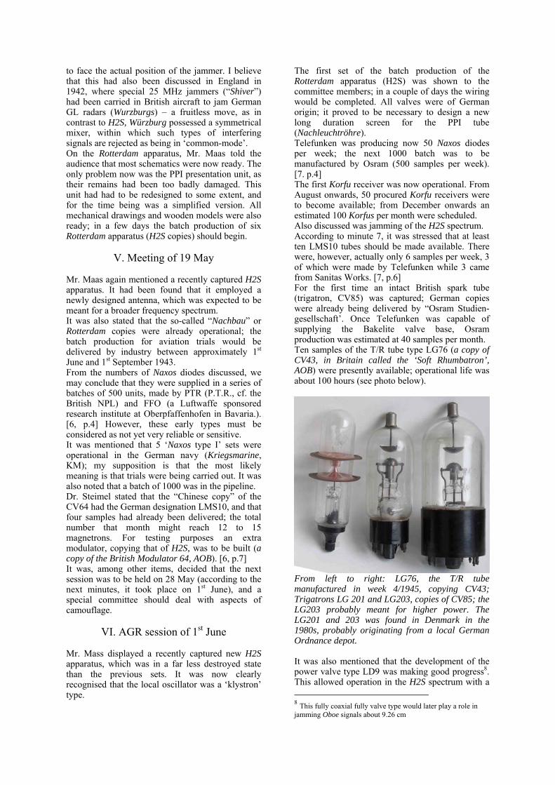
The first set of the batch production of the Rotterdam apparatus (H2S) was shown to the committee members; in a couple of days the wiring would be completed. All valves were of German origin; it proved to be necessary to design a new long duration screen for the PPI tube (Nachleuchtröhre). Telefunken was producing now 50 Naxos diodes per week; the next 1000 batch was to be manufactured by Osram (500 samples per week). [7. p.4] The first Korfu receiver was now operational. From August onwards, 50 procured Korfu receivers were to become available; from December onwards an estimated 100 Korfus per month were scheduled. Also discussed was jamming of the H2S spectrum. According to minute 7, it was stressed that at least ten LMS10 tubes should be made available. There were, however, actually only 6 samples per week, 3 of which were made by Telefunken while 3 came from Sanitas Works. [7, p.6] For the first time an intact British spark tube (trigatron, CV85) was captured; German copies were already being delivered by “Osram Studien-gesellschaft’. Once Telefunken was capable of supplying the Bakelite valve base, Osram production was estimated at 40 samples per month. Ten samples of the T/R tube type LG76 (a copy of CV43, in Britain called the ‘Soft Rhumbatron’, AOB) were presently available; operational life was about 100 hours (see photo below).
From left to right: LG76, the T/R tube manufactured in week 4/1945, copying CV43; Trigatrons LG 201 and LG203, copies of CV85; the LG203 probably meant for higher power. The LG201 and 203 was found in Denmark in the 1980s, probably originating from a local German Ordnance depot. It was also mentioned that the development of the power valve type LD9 was making good progress8. This allowed operation in the H2S spectrum with a 8 This fully coaxial fully valve type would later play a role in jamming Oboe signals about 9.26 cm

pulse power of 5 to 9 kW. The LD9 and related ceramic valves form a remarkable German wartime development9; LD9 is an entirely coaxial constructed valve, even the connections of the filament. In contrast, the well known American ‘lighthouse valve’ is coaxial only in respect of its upper part, whereas the base is a regular type octal. From August 1944 onwards, the LD9 played a role in tuneable jammers, mainly against OBOE signals at about 9.26 cm. Jammers for the SHF spectrum generally have strong limitations, as the frequency spreading employed is wide; a complicating element is the very narrow beam aperture of cm radar systems. Even today, jamming in this spectrum is still problematic.
VII. Session of 22 June 1943 Mr. Maas reported on Rotterdam apparatus Nr. 1. This consisted mainly of original British H2S modules; only in the event that none of the recovered British parts could be used did Telefunken make a substitute unit. Nr. 1 was first installed on top of the ‘Zoo bunker’ about 40 m above ground level; air trials were also undertaken at a flight level of 6000 m. The Germans may have been impressed by the screen presentation; it was, however, noted that picture quality deteriorated towards higher altitudes. In the course of the minutes of meetings, it was several times commented that some PoW interrogations were fruitful; Fl-Hauptingeneur Dr. Ruban10 of GAF suggested that they take onboard one of the test flights the PoW who had passed on such fruitful information, to give his opinion on the quality of the German installation and the original British H2S. [8, p.3] A list of who was receiving which Rotterdam serial type number was tabled. With the exception of Telefunken, who still kept the replica made with some British components, 5 sets were being delivered, to:
• Nr. 1 BHF • Nr.1a Telefunken hybrid type, for
ground tests • Nr.2 FW200 aircraft GAF • Nr.3 German navy (Kriegsmarine) • Nr.4 Fitted in an Me 410, E-Stelle
Werneuchen • Nr.5 GAF site Köthen • all deliveries to be concluded in July 1943
The next subject was the Berlin radar project, which was a German re-designed version of H2S -this being necessary as German aircraft generally had less free space available. Among the many
9 Telefunken. DE756028 appl.18.2.1938, E.Rahn; DE762380 appl. 29.10.1942, G.Tschoepe & W. Willwacher. The Russians copied them and these types still can be found on electronic rallies. 10 Fl = Flieger = Air
items discussed was that one of the Berlin versions should be equipped with a AEG type klystron.11 It was also mentioned that the HF section should be made modular, as this allowed a rapid response to new developments. The HF parts were later also employed in various other radars where the pre- existing measurement system remained intact; considering the highly stressed circumstances, this was a logical move. [8, p.4] The chairman, Leo Brandt, pointed out that the situation to be faced on the availability of various valve types used in radars was very difficult. It was stated that Telefunken made 3, and the Sanitas Works delivered 2, LMS10 copies of CV64 - in my opinion, quite a small number, and such a production must have caused problems; this number was to increase to at least 10 per week. Development of LMS10 for higher frequencies was being worked on by Telefunken. Twelve LG76 T/R tubes were now available, and the number of spark tubes LG201 (Trigatrons) had reached 20, with an additional 14 to be delivered shortly. In my opinion, all these relatively low numbers indicate that German industry had little room for new projects, for they were already over-stretched with multiple demands. Dr. Scheibe noted that Naxos, though designed for 9 cm, also operated on 3 cm.12A special type, Naxos-U for submarines, was discussed and a high pressure 9 (rotatable) antenna arrangement was shown, resisting 35 bar pressure (35 atü). From the text, however, I have the impression that this system later became known as Athos. Blaupunkt had now delivered 4 Korfu prototypes. The broadband valve type LV4 caused Telefunken so much trouble that these were all replaced by type EF14. In one of the discussions the application of an EF50 was mentioned, but the Germans apparently decided to use type EF14. Roderich type D jammers against Rotterdam had been tested, and the results were regarded as good, although its effectiveness could be reduced by decreasing the sensitivity of the Rotterdam radar, a point also valid for British H2S.
VIII. Session of 23 July 1943
The test flight of Rotterdam apparatus serial number 1 was discussed. This proved that the presentation screen did not always display a clear map; however, it gave enough information for typical landmarks. The range of this set was stated as 6 km, although I do not understand what this meant; was this due to ground clutter, or was the system itself insensitive? Bernard Lovell mentions that during the war he himself, on looking at a radar PPI screen, could not make much of it; it needed much training before operators became used to it. (some perhaps never did grasp it! AOB)
11 In Britain Blumlein also favoured the application of a klystron 12 Please refer to my paper on this [ref. 2]

It was of course stressed that a range of at least 20 km should have been possible; Telefunken had to improve both sensitivity and the resistance of the equipment against sparking at height (ionisation, AOB; Höhenfestigkeit). A report was given on the British radar frequencies observed during a night raid on Berlin; Korfu had measured frequencies between 8.9 and 9.3 cm. German intercept stations near the Channel coast in France (Mont Couple?), had also received British shore transmissions up to 1.4 cm; the Germans knew, probably from intelligence, the radar type to be SCR 602. [9, p.4] A new radar type was introduced, called ‘Rotterheim”, based on Rotterdam HF parts, combined with the existing very accurate measuring system of Mannheim radar. Mannheim radar represented the most accurate German system; its specifications were more or less equal to SCR 584, although it worked in the Würzburg spectrum of about 560 MHz. Rotterdam Nr. 6 was to be modified to the latest state of the art, and an additional batch of 14 Rotterdam systems was to be delivered, one system per week, from 1st November 1943 onwards. It was also stressed that extra HF modules should be made available to FFO and others. Shortages of supply had been encountered for:
• the LG76 T/R tube • the RD2Md (RD2Md2) tuneable
magnetron local-oscillator for Korfu, Berlin and, perhaps, Rotterdam apparatus.
• The power convertors (80 V ac), partly based on recovered British modules and Lorenz type LMU 1029
• Magnets; some of the Rotterdam copies were equipped with British magnets and the rest with electromagnets - it is clear that the Germans were in very short supply of high quality magnets!
• LMS10 were now produced at 10 samples per week by Sanitas Works.
The situation on measurement equipment was extremely stretched. It was intended to produce 300 Roderich jammers per week; the bottleneck was, however, the supply of valves.
XI. Session of 2 September 1943 A further report on Rotterdam copy number 1 dealt with tests against “spoof mirrors” at the Schwielowsee, the investigations focussing on the effect on the PPI display13; this Rotterdam apparatus was mounted in a He 111. Then the purpose and location of all 6 H2S copies were 13 Some were known as: Trieberg-Spiegel
summarised successively; it was also mentioned that a Korfu radar search receiver had been placed on the Eiffel tower in Paris.
LMS10 serial number 0835; our museum sample carries number 0587. Note the unconventional bulb on one of the filament glass feeders; this was to keep the vacuum sufficiently high. Dr. Steimel reported that availability of the LMS10s being made at Sanitas Works was for the moment sufficient [10, p.4]. It was, however, noted that, in the time between the meeting and the writing /editing of the minutes, the Sanitas branch where LMS10 was manufactured had been totally destroyed. In an emergency meeting it was decided that Telefunken should start producing LMS10 again, at up to 5 units per month! It was stressed that every precaution should be taken to safeguard the lifespan of the scarce LMS10s; all unnecessary tests should be stopped for a period until delivery resumed [10, p.5]. It was noted that the lifespan of the LG201 trigatron spark tube was still too short, and efforts were undertaken to increase this figure. Ten samples were supplied per week, and at this stage the situation was regarded as being satisfactory. LG76 production was 3 to 4 samples per week. Dr. Steimel reported that safety measures should be taken when operating the tuneable magnetron RD2Md2 in a cavity, and suggested it was better to use an external Lecher system [11, p.24]. It may be of interest to British historians that they mentioned that the prototype copy of the British reflex klystron (Reflector Klystron CV67), used as the tuneable local oscillator in H2S, would be available within 3 to 4 weeks. Steimel also dealt with problems in increasing the power of German magnetron copies up to 150 kW; the pulse voltage was to be increased up to 40 kV. It is also noted that the chance of tuning the resonant frequency of German magnetron copies for a few mm (λ) were estimated to be good.14 Production figures were given for the availability of Roderich D jammers.15 [10, p.6]
14 By means of manipulating its strapping? If that was the case, they must have understood what strapping was actually used for. 15

XII. Session of 11 September 1943 A report was given on trials with different kinds of electronic spoofing. Various sorts of techniques were dealt with, among them Trieberg-Spiegel (Trieberg-mirrors); these are reflectors which reflect signals approaching from any direction back towards their origin, causing a very intense reflection on presentation screens, broader in appearance than the actual size of the reflector. Landmarks such as lakes and rivers could thus be camouflaged. [12]
XIII. Session of 22 October 1943 It was announced that Dr. Plendl was to be replaced by Dr. Rössler on behalf of BHF. 16[12, p.4] Prof. Esau emphasised, among several points, that the Germans should be strongly motivated never again to be faced with a fundamental shortfall in modern radar development without German interception (intelligence) having noticed the fact.17 The next point was a report on the position regarding valves for the cm spectrum. Three entities were involved in designing magnetrons for the spectrum of 4 to 6 cm. They had achieved powers comparable with that of CV64 on 9 cm18; however, their mechanical size was different. Telefunken had built a 100 kW magnetron for 9 cm, though it was not yet able to test this through lack of an appropriately powerful pulse modulator. There followed a report on attempts to make a tuneable power magnetron. A representative on behalf of Lorenz spoke about trials on a British detector discovered in a crashed British aircraft near Amsterdam; this, following German practice, had been code-named ‘Amsterdam’. It had been found that this detector diode was relatively insensitive to shock vibrations (besonders unempfindlich) [13, p.7-8] AGR then dealt with the situation regarding test equipment. Wavemeters were now available from 2.5 cm onwards. A bottleneck was the availability of power signal generators (Leistungsmeßsender). They possessed only two sensitivity generators (Empfindlichkeitsmeßsender). New test gear was under development for the spectrum of 5 to 30 cm. It was also apparent that they lacked Signal Standards (Normale). [13, p.9] Mr. Maas reported on the state of development of long persistence CRT screens. German tubes were not yet satisfying requirements and they could only investigate enemy screen fragments, as so far all CRTs discovered were broken.
16 Plendl was regarded as responsible for Germany’s failures on suitable cm radar techniques 17
18 FFO at Gräfelfing Bavaria, Sanitas Works and Telefunken
The Skiatron (Black trace tube = Blauschrift-Röhre) was discussed as a way of achieving long screen persistence at will (as it was in Britain). [14]. Mr. von Wrangel reported that it had been discovered that British fighter aircraft used a new type of radar system at 9 cm (10 cm?). It was regarded as most likely that these kinds of panoramic radars were also operational in Britain’s backyard (Hinterland). [13, p.10] Capt. Dr. Becker reported on a trial between a Seetakt radar on 80 cm, a Telefunken experimental set called Eisvogel on 20 cm consisting of two small Würzburg antenna mirrors (one for receiving, the other one for transmitting), and a Rotterdam apparatus. Although this last system was 10 times less sensitive, its results were equal to, perhaps even better than, the first two. It was significant that the H2S copy was far smaller than Seetakt and Eisvogel.19 It was also reported that Rotterdam set Nr. 4 was far more sensitive than the other copies, and had been forwarded to the GAF Establishment Werneuchen (Erprobungsstelle also known as E-Stelle) near to Berlin; its range was between 60 and 70 km.
Berlin A pulse-transformer for stepping up the pulses from the delay-line circuit to feed into the LMS10 magnetron In my opinion this might originate from various coincident factors, such as a better mixer diode, a better performing LMS10 and, perhaps, the pulse modulator performing better. As we have already noted, the Germans faced serious shortages of good high µ materials; a significant component in H2S-like radars is the pulse step up transformer between the pulse-modulator (British Modulator 64) and the magnetron.
19

HT delay-line of the Berlin type A pulse modulator, perhaps originating from a FuMO81 apparatus in Denmark. Right capacitor marked week 42/1944 As in normal production runs, it can happen that on occasion all variables work in a positive direction. This implies that the potential specs of the components are being met, but also that sometimes local factors or temporary situations might have been influenced by the circumstances of the war. It was also reported that a Naxos Z, placed on Telefunken’s test tower (auf dem Turm) detected the direction of enemy bomber aircraft at distances between 180 and 200 km! (reference 2).
XIV. Session of 11 December 1943
First, the holders of the initial five Rotterdam sets were set out20. A batch of 14 Rotterdam sets was in production at Telefunken; however, owing to bomb damage at the factory at Schulze-Wechsungen, production had been delayed. Everything possible had been done to keep the time lost as short as possible. [15, p.4] Flight chief engineer Huschka (Flieger-Haupt-ingenieur) reported that towns could be seen at distance of 45 to 50 km. Comparing Naxos Z interceptions of both Rotterdam and enemy radars, it was concluded that enemy pulse power was achieving much higher output levels. It was also recognised that the CW pulse power of the Roderich D radar jammers was as yet very insufficient. Dr. Goos made the point that it is important to improve the performance of the cathode of the LMS10. The cathode was also a bottleneck, as this was the source of electrons directed towards the cavities. As I x U = P, it is clear that when one can
20
increase the parameter I, output accordingly increases; this phenomenon resulted in British patents, and my reference [16] links the reader to the key British patents. It was pointed out that Telefunken could only deliver 5 LMS10 samples per month (!) but that by the end of December, Sanitas would have started up production again (perhaps at another site, after the bombing). The production target was 100 units per month, so as more realistically to meet the demand. Telefunken was to provide to Sanitas Works a special test set (Prüfsender) for testing the parameters of the LMS10 magnetron. Gema were to loan a pulse modulator of 60 kW, probably to Telefunken, as they were working on high power magnetrons. It was also decided that Gema would build pulse modulators for testing LMS100 types (100 kW). The first prototype of LMS11 providing 15 kW at 5.18 cm was also ready. Telefunken were also working on a 3 cm magnetron type (10 kW). Dr. Kretzmar of RLM was to look for applications; note here the CIOS report on the visit to the Philips Works Eindhoven in September 1944, where he is quoted several times [17]. An interesting question would be whether they were in fact copying a captured American 3 cm magnetron, or whether this was research on their own behalf. According to this CIOS report, Kretzmar was evidently heavily involved in this field. PTR (the NPL equivalent) was now successfully working on the production of SHF diodes. The first synthetic samples were delivered to Telefunken for testing. Brandt stated that new test equipment for diode testing was now available. On Naxos Z trials it was noticed that even scattered radar pulses could be picked up; Naxos range was about 100 km. A batch of 200 Naxos Z had been acquired. Historians may find it of interest that Brandt pointed that short duration DF systems should be provided, for he expected that in the foreseeable future the Allies might be forced to switch on their radars for only a short period when nearing their targets, and in the second half of 1944 this actually was the case. The Allies’ lavish deployment of HF signals of all sorts was becoming a most useful source of information for the Germans.21 It was also stated that a special receiver was under development at LMT in France for 5 – 15 cm, employing velocity-tubes - “geschwindigkeits-gesteuerte Röhren”.
21 [18, p.59-60 ] para. 345. Discussions and argument swayed round all these points until 22 July 44, when the Chief Signals Office recommended to the Air Staff that Monica, H2S and A.G.L. (T) should be kept switched off until the Bomber Force was within 40 miles of enemy territory.... 348. Before the end of the War in Europe, H2S was being restricted not only on the approach, but also, due to the intruder menace, on the return flight as well. This was not the only reason; the Germans tracked bomber aircraft almost constantly due their lavish transmissions.

XV Session of 25 February 1944
Brandt opened the meeting with the announcement that Albert Speer had established a “Funkmess-Sonderkommission” headed by Dr. Rottgardt, who was also technical director of Telefunken.22 [19, p.3] Brandt also noted that a central depot with a laboratory for captured equipment had been established, housed in a bunker in Berlin; all major companies and institutions would be joined in this project. The audience was also told that all Rotterdam test flights would be coordinated, headed by Dr. Kotowski (Telefunken). Mr. Maas gave a report on the situation concerning the Berlin-A radar, based on the principles of H2S, though adapted for German specifications. It consisted of four modules: Antenna, Module I (Feld I), Module II (Feld II) and the PPI display unit (SG224, AOB). It was stated that its total size was half of that of H2S, and the total weight was also reduced by 60 %.
Basic concept of the Berlin A radar system [19]
Later in 1944 this concept was realised with success, although by autumn 1944 the war situation had so much changed in favour of the Allies that it was rarely used by one of its main promoters, the Luftwaffe (GAF); the navy (KM) did use it, with some success. The major change was that the antenna motor with integrated deflection goniometers was replaced by a much smaller version employing selsyns instead. One important advantage was reduction in weight, and the selsyn system allowed up to three external (slave) PPI displays to be linked onto the system. This was mainly for navy applications, but their capital ships were no longer operating.23 When we view this illustration, we can see that various modules must have been built and perhaps tested; noting that this
22 Speer was minister for armament and ammunition 23 Steuergerät = control unit; Sichtgerät = PPI unit; Feld I contained the pulse section; Feld II incorporated the HF stages with transmitter and receiver front-end.
meeting took place on 25th February 1944, we may assess that Berlin A was designed after, say, March 1943 and that one prototype must have been ready about the end of 1943 or the beginning of 1944 - considering the war situation and totally novel techniques, a real challenge!
The Museum’s Berlin A, PPI apparatus, serial number 446. It is clear that the PPI photo shown left is equivalent to our unit produced at least in late 1944 or early 1945 In contrast to British practice, the dielectric antenna (Polyrod) rotated at 400 rpm! It is also noted that test flights in a FW200 had shown that the new Berlin A radar performed as well as the Rotterdam copies. Practical application in the German air force might cause problems, as the screen presentation was quite different from what they were used to. In this respect we have to remember Bernard Lovell’s wartime comment: “that he was really astonished that the radar operators could recognise anything”! “Berlin U” designed for submarines was also discussed; they did not as yet know that the beam aperture was far too narrow, and that this concept would not prove suitable for U-boats. A list of users was provided for the Berlin A test sets (‘Versuchsmuster’, V 1 to V9) – a fact which means that at least 9 Berlin A sets had already been built (0-Serie). It was also noted that the supply of LMS10 was extremely poor, and Mr. Helbig of Sanitas was specially invited to explain the circumstances. XVI. Capture of “Meddo apparatus”, H2X
When exactly this 3 cm set was captured is not recorded; however, my estimate is that it must have been in late 1943. ‘Meddo’ is a tiny village in Holland near to the German border. For a crashed aircraft the remains of this set are in a remarkably good condition! It is no wonder that the Germans had immediate access to 3 cm (actually 3.2 cm) technology. Once again, they responded swiftly, and they must have managed to copy the 3 cm magnetron within weeks, since according to interrogated Philips staff [17] they had met with Dr. Kretzmar some time earlier than September 1944.
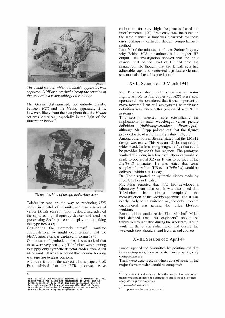
The actual state in which the Meddo apparatus was captured. [19]For a crashed aircraft the remains of this set are in a remarkably good condition. Mr. Grimm distinguished, not entirely clearly, between H2X and the Meddo apparatus. It is, however, likely from the next photo that the Meddo set was American, especially in the light of the illustration below24.
To me this kind of design looks American
Telefunken was on the way to producing H2X copies in a batch of 10 units, and also a series of valves (Musterröhren). They restored and adapted the captured high frequency devices and used the pre-existing Berlin pulse and display units (making this type Berlin D). Considering the extremely stressful wartime circumstances, we might even estimate that the Meddo apparatus was captured in spring 1943! On the state of synthetic diodes, it was noticed that these were very sensitive; Telefunken was planning to supply only synthetic detector diodes from April 44 onwards. It was also found that ceramic housing was superior to glass versions. Although it is not the subject of this paper, Prof. Esau advised that the PTR possessed wave 24
calibrators for very high frequencies based on interferometers. [20] Frequency was measured in the same manner as light was measured; for those days perhaps a difficult, though comprehensive, method. Item VI of the minutes reinforces Steimel’s query why British H2S transmitters had a higher HF output. His investigation showed that the only reason must be the level of HT fed onto the magnetron. He thought that the British sets had adjustable taps, and suggested that future German sets must also have this provision.25
XVII. Session of 13 March 1944 Mr. Kotowski dealt with Rotterdam apparatus flights. All Rotterdam copies (of H2S) were now operational. He considered that it was important to move towards 3 cm or 1 cm systems, as their map definition was much better (compared with 9 cm systems). This session assessed more scientifically the implications of radar wavelength versus picture definition (Auflösungsvermögen, Ersatzdipol), although Mr. Stepp pointed out that the figures provided were of a preliminary nature. [20, p.6] Among other points, Steimel stated that the LMS12 design was ready. This was an 18 slot magnetron, which needed a less strong magnetic flux that could be provided by cobalt-free magnets. The prototype worked at 2.7 cm; in a few days, attempts would be made to operate at 3.2 cm. It was to be used in the Berlin D apparatus. He also stated that some samples of new 3 cm T/R cells (Nulloden) would be delivered within 8 to 14 days. Dr. Rothe reported on synthetic diodes made by Prof. Günther in Breslau. Mr. Maas reported that FFO had developed a laboratory 3 cm radar set. It was also noted that Telefunken had almost completed the reconstruction of the Meddo apparatus, and it was nearly ready to be switched on; the only problem encountered was getting the reflex klystron working. Brandt told the audience that Field Marshal26 Milch had decided that 150 engineers27 should be transferred to industry; during the week they should work in the 3 cm radar field, and during the weekends they should attend lectures and courses.
XVIII. Session of 5 April 44 Brandt opened the committee by pointing out that this meeting was, because of its many projects, very comprehensive. Trials were described, in which data of some of the major German radars could be compared: 25 In my view, this does not exclude the fact that German pulse transformers might have had difficulties due to the lack of their adequate magnetic properties 26 Generalfeldmarschall 27 I suppose academically educated

• Seetakt λ = 80 cm, 1.5 kW • Würzburg λ = 55.1 cm28, 8 kW • Mannheim λ = 53.6 cm, 12 kW • Eisvogel λ = 21.2 cm, 5.5 kW • Rotterheim λ =9.1 cm, 8 kW29
Pro and cons were discussed; the advantage of cm radar was very significant for low level interceptions. [22, p.6] I regard this list as interesting in that it shows the way in which the AGR committee was approaching its many tasks. These tests were carried out near Travemünde (NVK Pelzerhaken) to investigate the radar response from the impact of target reflections, such as from aircraft, periscopes, submarine conning tower, and also on shell bursts30 for 15 and 28 cm calibres on the water surface. Much technical and theoretical effort was put in. An item of discussion was whether what they saw was the impact on the water surface or the ionisation of the shell trajectory.
Experimental type “Eisvogel” radar apparatus (20 cm), with separated transmitter and receiver, both employing Würzburg frames. The front unit incorporates the receiver, the rear the transmitter One of the topics discussed was the nature of the property of reflection of various materials, such as stone, brick wall, iron, etc.; they called this the “colour” of the reflection31. Nowadays, with modern radar techniques this is possible. [22, p.18] Also debated was the maximum resolution of cm radar. They observed that the pulse-width by itself already represented a transit range of 200 to 300 meters (as in the Rotterdam apparatus); consequently, this only could be countered by means of sharper (smaller) antenna beams32 and with shorter radar pulses. It was also discussed whether it was practical to use additional reflectors to camouflage potential targets. Wide ranges of trials were discussed during many
28 This means that it operated at a lower than usual frequency 29 Mannheim apparatus fitted with Rotterdam HF modules combined with the existing measuring sections 30 Geschosseinschlägen 31 Equivalent dipole number 32 Antennebündelung
AGR committee meetings, though it proved to be nearly impossible to cover wide areas like lakes and industrial targets. Attempts were made to camouflage lakes, but it was discovered that simply by reducing the sensitivity of the radar system a lake was still visible. Smaller “spoof” targets could provide more reflections than expected, which might confuse radar operators. Trials with the Rotterdam apparatus “Wiesbaden”: a British bomber had crashed near Wiesbaden, and its H2S like radar set captured scarcely damaged. Restored to functioning again, and compared with the sets captured previously, it gave far better pictures, and also provided a longer measuring range. It was stated that German flights at 2000 m altitude, displayed radar targets up to 250 km. [22, p.33]. The quality of the picture was also far better than that of the early H2S apparatus. It was, however, not yet known why it performed so much better; perhaps it was the improved antenna design. Dr. Rottgardt thought that it might be helpful to interchange the Wiesbaden modules step by step to find out what really made the difference. (It will be recalled that the Rotterdam apparatus was in most respects a copy of the H2S equipment). It was also noted that an additional British radar set had been captured near Gütersloh. This set could not yet be exploited as the antenna was not extant (perhaps destroyed by the crash, AOB) [23, p.34]. Dr. Knoll suggested that the antenna of the Wiesbaden apparatus should be connected onto the Gütersloh set. Fishpond was also a matter of discussion.33 Brandt told the audience that measurements of the output power of the Wiesbaden apparatus gave the figure of 12 kW. Next to be discussed was the finding of new “Meddo” type radar modules. Among many photos, one of the American 723 reflex klystron was displayed. As this type is very well known, I have omitted it; the Germans must have known of the existence of this type of signal source since, say, late 1943 or early 1944. It was suggested that owing to the fact that the American permanent magnet was covered by “Papp Maché-Masse” (4 mm) its properties must be porous. In contrast to British practice, the Americans employed thyratrons instead of sparking Trigatrons. The Lorenz-designed Hohentwiel (FuG200) radar used also thyratrons in its pulse modulator. [23a] The Germans must also have captured a “Norden bombsight”. Mr. Grimm reported on various difficulties encountered with German Rotterdam apparatus. [22, p.44]
33
I do not know whether this code-name originated from post war editing or that it was known via PoW interrogations

Combining various items of information dispersed in the text, we can assume that the 9 cm spectrum was called range A (Wellenbereich), and that of 1 cm was known as range E. It was also reported by Capt. Giessler that they intercepted on the Channel Coast British radar signals at 3.2 cm with a PRF of 650 Hz, and that after 3 to 4 antenna rotations this system was (temporarily?) switched-off; its transmission had been recorded on gramophone records. [22, p.51] 30 specimens of Naxos Z were now available, though not yet to the forces, meaning, I believe, application in fighter aircraft. Brandt stressed that larger quantities could only be acquired by means of a ‘Special Production Programme” (Sonder-aktion). Two Naxos ZX apparatus for combined 9 and 3 cm were now available; it was expected that problems encountered would soon be solved. A series of 1000 Navy Naxos-Finger was in production with some modifications; with attached reflector this was called Fliege. Also noted was that the “Tunis”34 apparatus would soon enter service, covering 9 and 3 cm (this code-name was not mentioned, but the set was later thus designated. [23]). Though not specifically minuted, a talk might have been given on a “magnetic flux compass” for navigation, probably captured from a crashed Allied bomber35. [22, p.53]
IXX. Session of 26 April 44 The first item was the capture of an intact US B24 Liberator aircraft which had made an emergency landing near Calais. This was the first untouched Meddo type apparatus that had so far fallen into German hands. I do not know exactly when this happened; I estimate about early April 1944. However, it was stationed at Wilmington and/or Dunkeswell36 [24, p.21, 19]. This aircraft was later transferred to Werneuchen and flown with German designations37 [24, p.7] There commenced many flights with this excellent aircraft. In the course of discussion, quite some time was spent on a summary made during the interrogation of a US PoW radar operator, probably the one from the crash-landed Liberator; he spoke also about its application against German submarines. One question relevant to this paper was raised by the interrogated PoW; he asked why the Germans had stopped jamming of their radar in October 1943 when the plane was near the Spanish coastline of the Biscay Bay, as it had not been encountered along the French coastal line? The implication of
34 Also known as Cuba I 35
36 It is not entirely clear whether this person (PoW) belonged himself to the Dunkeswell site 37 Hoheitzeichen
this query is that we may assess that the Meddo apparatus was operational from, say, early 1943 onwards! However, every time they encountered this jamming, which made radar observations impossible, they had to search a sector with a radius of 30 miles, to find out what had caused this nuisance. The first time he encountered equivalent jamming was near the Bermudas on, from his memory, 20 May 1943.
German photo of the captured radar PPI console of AN/APS15, from a US B24 Liberator aircraft which landed almost untouched near Calais The next subject dealt with was Düppel or Window (chaff). German trials had proven that the only way to get rid of Window interference was to move to the cm spectrum, where to obtain a particular level of radar jamming the quantity of window needed multiplied in the ratio maybe 1: 25. In British sources [18, p. 2] it was pointed out that: On this theme, it is probably true to say that the enemy had at the close of the War reached a point of technical development – long foreseen and always expected – beyond which there would have been great difficulty in pursing him further; the reference is to centimetric radar which, had it appeared earlier, might well have given the enemy an overwhelming advantage. … Leo Brandt the chairman gave an account of the work of the AGR committee which had then existed for just over a year. The availability of wavemeters for the SHF spectrum was increasing, but was still very unsatisfactory for the upper regions. It is illustrative that many dates for expected delivery for some items go out to December 1944![24, p.32] Another subject considered was experience with Korfu receivers in the 9 and 3 cm spectrum.

The Museum’s Korfu receiver of late 1944 or early
1945. It is equipped with plug-in units for the S-Band; there exist also plug-ins for X-band
The latter used frequency tripling for the local oscillator (Oberwellenmischung). This caused considerable reduction of sensitivity38, and consideration was given to adopting a 3 m parabola antenna, to compensate for this signal loss. [24, p.54] Mr. Grimm gave a report on bringing Rotterdam X (H2X) back to working order again. Mechanically all was now in order; missing modules were adapted from the Rotterdam apparatus (H2S copy). Since April practical trials had been underway at tower “Frieda”; the achieved range was not yet satisfactory. One of the major problems was the replacement of the first local oscillator on 3 cm; the German RD2Mg magnetron was not working reliably. We will see later that they finally resolved this problem when they redesigned the US 723 reflex klystron, given type number LD20. [24a] One of the problems encountered was caused by the German version of the rotary antenna; in some sectors, the wave guide matching jumped and in these sectors the beam was getting a split-pattern (bore-side was a null). A wide range of points on the implications of PPI projection was also dealt with. Some of these were known as “radial distortions”; another problem was that H2S used electrostatic deflection, whereas the German Berlin A PPI was, like the US Meddo apparatus, equipped with magnetic deflection. The disadvantage of using deflection plates is that the sensitivity for both X and Y sections is not equal. Dr. Goos of the Luftwaffe establishment Werneuchen reported on trials with the Wiesbaden apparatus. It will be recalled that that this was a new type of H2S apparatus which fell into German hands complete, including the antenna. In the previous talk distortions as against a map had been discussed. Goos noted that they had seen a mountain at 130 km distance. He also reported that some cities were visible and some invisible on the PPI display, and explained why this could happen. [24, p.82] Reports were also given on the radar
38 Due to the reduced level of mixing power. Also known as mixing current
visibility of U-boats. A large range of photos was shown which compared the screen resolution of the Wiesbaden apparatus compared with their own Rotterdam apparatus (H2S copy); screens were shown together with the associated map, i.e. what an operator actually saw and what it theoretically was. He mentioned, probably proudly, that the close- range resolution of their Rotterdam apparatus was better than that of the original British Wiesbaden apparatus. [24, p.89] We must, however, remember that the Rotterdam copy at Werneuchen performed better than some other H2S copies. The tendency was that all H2S copies were, step by step, performing better. Dr. Angenetter (who later crashed on an FW200 test flight) reported on Berlin A screen pictures. While the Berlin A screen picture (CRT type LB9N) was brighter than that of Rotterdam apparatus, it was on the other hand a little more “lumpy” (etwas unruhiger). The Germans used in their early Berlin A radars (FuG 224) a heavy, complicated goniometer which provided the radial sweep (deflection from the centre of the PPI tube); the nuisance was proven to be due to the mechanical tolerances of the mechanism, and later they adopted a simpler selsyn system. The problems mentioned might have been caused by this phenomenon. [25] Another problem encountered was the fact that the dielectric antenna arrangement (Polyrod) displayed so called radiation gaps, owing to the principle of their antenna-phasing-technique. This caused some height-dependent gaps (Nullstellen), particularly in the vertical plane. It was noted that very comprehensive antenna research was necessary, particularly in respect of 3 cm radar.
XX. Session on 31 May 44 Dr. Kotowski started this new session with a report on aspects of navigation with cm radar. It was desirable that radar should achieve short range recognition down to about 100 m, but the German systems available until then (Rotterdam and Berlin A) often had 2 - 3 km minima. It was not yet clear what caused this problem; it was noted that asymmetry inside the (antenna) deflection gonio-meter might be one cause of elliptical radial screen distortions. [26, p.3] However, steady technical improvements had already reduced this nuisance. When all faulty parameters were at their worst value, a 20 % system error was possible.39
39

Further consideration was given to the application of cm radar as a bombing aid, which might appear curious as the GAF relied on defence tactics.
This radar screen photo was taken from Berlin A serial number 5 (V5) at an altitude of 500 m of the Scharmützel-lake In the course of this report it was mentioned that the Rotterdam apparatus Nr. 2 at NVK in Pelzerhaken has been improved considerably and it was considered that it performed as the Wiesbaden apparatus (a genuine improved H2S, mark II?). Dr. Goos of Werneuchen told the audience that their FW200 aircraft with Berlin A serial number 5 onboard had crashed. It was noticed that the irregular instability of the screen centre (locus) was at maximum 4 x 4 mm², and still caused by mechanical imperfections in the antenna goniometer. Trials were carried out to counter system imperfections of various kinds. [25, p.12] It is also clear that the Germans had commenced considerable fundamental studies on the properties of Düppel (Window, chaff). Mr. Maas reported on trials with the Rotterdam X apparatus (German copy of H2X). They still encountered problems with the signal of the first local oscillator, as this was still a magnetron whose signal was multiplied to cover the 3 cm spectrum (Oberwellen zur Mischung). Owing to the reduction of the signal level injected, sensitivity was reduced to 1: 2 to 1: 3. A copy batch of 10 samples was in the pipeline. Drawings of the front-end wave guides were handed out to the attendees. It is interesting to compare the design differences between British H2X and US AN/APS15. It is clear that these details were studied to derive later their own 3 cm radar concept, which most likely would be in some respects a copy of both techniques. [26, p.45, 46]
The upper drawing shows the front-end of British H2X and the lower drawing the American improved design used in the Meddo apparatus (AN/APS15). The next minute does not entirely reflect the status of 31 May 1944, but was modified later and reflects the position at 1st July 1944.40 For this occasion Mr. Maas dealt with the demands of GAF and the German navy (KM). Both would acquire Berlin A derivatives (Abkömmlingen). [26, p.48] To overcome the problems caused by the so-called “black sectors” (Nullstellen) it was decided to mount the dielectric antenna arrangement on a kind of elevator mechanism (Fahrstuhl) to determine the position where these nulls had the least effect; the results and positions found should then indicate the exact position of the Berlin radar antenna for a given aircraft type.41 Then he continued with: Von dem Gerät “Berlin A” sind bisher ca. 35 Stück ausgeliefert worden. Now for the first time we have a tangible figure! This proves that Stephen Travis’ point in his 1995 40 Because the minutes were edited later, new facts have to be covered 41

dissertation is not correct; he might have followed a (summary?) translation of the AGR minutes, but certainly has not read it entirely. He states not 35, but 10, samples were actually produced, which might have been based on the 10 Berlin A experimental prototypes V0-V9. [27] Then Mr. Maas noted: Es befindet sich von dieser Anlage eine Nullserie und eine Groß-Serie in Fabrikation, so daß in einigen Monaten schon erhebliche Stückzahlen dieses Gerätes zur Verfügung stehen werden. We might now assess that the 35 already delivered Berlin A radar sets was part of the ‘null’ batch. [26, p.49]
Berlin A transmitter and receiver front-end, based on H2S technology. Nevertheless, the German design differs as their pulse forming network is an integral part of this module, whereas British H2S mounted it in the modulator unit. The electro-magnet for the magnetron field is also visible. Please note its serial number, 216. We must, however, take into account that the fortunes of war had changed so rapidly against Germany that the planned large production numbers of Berlin A apparatus might not have been reached - although in fact the maximum industrial output of radar systems was reached in December 1944! To my knowledge, 500 systems were built, of which 100 might have been operational when the war ended. Perhaps 150 HF modules, containing the transmitter and receiver front-end (including the IF section) were mounted in adapted radar systems. For instance, some Freya LZs were converted into Renner I and II, and some Mannheim sets were converted into Rotterheim. Likewise, night-fighter aircraft had 9 cm radars like Berlin N 1 and/or FuG240/1, which was operational in the final days of the war when it achieved several victories. [28, p. 118-124] However, Mr. Maas then discussed Berlin N1 for night-fighters, which had the HF components of Berlin A though using the SN2 radar display. An interesting feature of this system was that it had inside the aircraft nose a steerable parabola dish of 70 cm diameter, directed by means of a joystick. The first 50 samples of Berlin N1a were to be delivered in July, as result of a ‘special program’ (Sonderaktion). Berlin N2 was scheduled to have a larger antenna which provided four sectors (quadrants).
Egerland Anlage, consisting of Kulmbach and Marbach
LD 20, the German reflex klystron, derived from a captured US 723 reflex klystron tube. Courtesy of Mr. Trochelmann, Germany Berlin N3 was meant to be based on Berlin A, though employing a special antenna rotating at 400 rpm. Berlin N4 was also under consideration. Kulmbach FuMG74, based on Berlin A (HF), for Flak control was also in the pipeline. This set was operational early in 1945, the first test version being scheduled for 1 August 1944. E-boats (S-Boote) were to be equipped with “Berlin S”. Renner I and II were based on a regular Seetakt though with Berlin HF modules, including the IF section; Renner II had a panoramic (PPI) display based on the Lorenz PPI (Sternschreiber). On page [26, p.58] Mr. Maas reported on the new 3 cm sets under development known as “Berlin D”. For obvious pragmatic reasons, only the 3 cm HF section was newly designed, whereas the rest of the system relied on the Berlin A units (Feld I, available in larger numbers). They encountered some problems with their local oscillator magnetron. It was also stated that the German LMS12, based on the American 3 cm magnetron, was giving twice

the output power of the Germany H2X magnetron copy42 (2: 1). [26, p. 58] The next topic, given by Dr. Knoll, was on fluorescence substances for PPI screens. He stated that the properties of the American PPI CRTs were much better than the German and British PPI screens; he then explained the use of a two layer screen. Lorenz was ordered to produce samples of the modified properties. It was planned that in the next AGR session comparative results should be available. The trials were thus between both Telefunken and Lorenz screens in respect to the American PPI screen. Dr. Steimel next reported on aspects of spark tubes (trigatrons); he stressed that the actual voltage of the transmit pulse had an important impact on the transmit frequency. He then continued that the American Meddo apparatus took very great care to keep this within narrow limits; use of a thyratron was favoured. On the LMS10, Steimel stated that it had proven to be possible to increase output power up to 50 kW when the anode pulse voltage was increased by 20 %. With the magnetic field also increased by 10 %, the power factor would be then about 30 %. It was hoped that this would also work for the 3 cm LMS12. First trial samples of LMS100 had been made.
XXI. Session of 26 July 44 Brandt opened the session and told the audience that from now on invitation cards would be introduced; access to the meeting would only be possible by those having one. This was enforced for security reasons. It was also laid down that this session would deal mainly with fundamental topics, and that every second AGR meeting would focus on theoretical aspects. Without going into detail, what was reported included:
• Dielectric properties of reflectors at very high frequencies.
• reflection coefficient of sea water; • dipole equivalence; • reflection of rocket exhaust flame gases;
reflection properties of fixed targets; • radar formula; reflexion properties of flat
and convex planes; • dipole equivalence of various aircraft types
versus wavelength; • Düppel (chaff);
The next topic of discussion was the actual state of development of valves for SHF.
42
• LMS100; 9 cm, 100kW - research completed
• LMS11; 5 cm, development cancelled • LMS12; 3 cm, 10 kW - research
completed • LMS13; 1.5 cm, 5 kW, research to be
completed shortly • LMS101; 9 cm, 1000 kW, research in
progress [29, p.20] Scheduled to arrive was a magnetron for 1.05 cm A report was then made on magnetrons designed at FFO, PTR and elsewhere. [29a] Work on klystrons was also in progress and new results were due. Dr. Labus’ tuneable klystron was noted (9.6 – 11.4 cm). [29, p.24]
FFO designed a magnetron copy for 1.5 cm43; whether this really was for 1.5 cm is not known to me. The curious black glass envelope attached to one of the filament legs contains getter material, which must have been done to keep the vacuum high. Allied magnetrons lacked this facility, but possessed much better glass to metal seals, using gold plating. It was however, noted that the actual production capacity was too low, and assistance was necessary from other sources. In one of the AGR sessions it was noted that making a single test valve sample caused the hold up of a production line for one valve type for a day! T/R cells operating between 3 to 1 cm had been investigated and future prospects were fair. However, a major obstacle was the capacity of the
43 [29, p.21]

cell; it was considered that ceramics might provide the solution. Next to be considered were tuneable power magnetrons, such as LMS20 for 9 cm and LMS22 for 3 cm; the RPF (Reichspost-Forschungsamt) was also working on this subject. It was discussed how the Meddo magnetron might be tuned in frequency; it was clear that a kind of membrane was used and eventual tuning must be an exception. With the dimensions (properties) of the internal structure of the Meddo magnetron copy, it was possible to operate at λ = 1.55 and 1.05 cm. It was noted that tolerances might be a limiting factor. [29, p.33] The next item dealt comprehensively with aspects of “temperature inversion” causing abnormal ranges (refraction in the troposphere, troposcatter?). Dr. Steimel’s final report was on “pulse modulators”; it was noted that the AN/APS15 (Meddo apparatus) showed signs of special attention to keep the pulse amplitude as constant as possible.
XXII. Session of 1 September 44 This is the last recorded session of the AGR Committee. Dr. Fränz of Telefunken and Dr. Goos of the E-Stelle Werneuchen presented a further report on Rotterdam and Wiesbaden apparatus trials. Next they dealt with Flak guiding systems controlled by radar, particularly focussing on servo control mechanisms. [30, p.2]; also of interest is the ‘prediction’ (Vorhalterechnung) of targets. An item of interest is the implication of the travelling time of flak shells, which might take say 20 seconds.44 A major problem is the variance of system parameters of various kinds (statistisch schwankenden Grösse), such as the accuracy of the radar plot; the transfer of the data such as distance bearing in azimuth and elevation; the transmission of these data towards the predicting system, often accomplished by means of servos and analogue computers; and the delay in passing on these data. Taking an aircraft with an air speed of say 360 km/h (V = 100 m/s), it is evident that the travelling time of 20 seconds (representing 2000 m) might involve drift by wind speeds at higher altitudes. Also important is the speed with which the predicting system works in handling the various data. This must also be conveyed to the flak
44
(translated in local bearing and fuse-timer setting). It is clear that all these factors play a significant role in finally hitting a flying (moving) target. These implications are of a fundamental nature and so were not only of concern to the Germans, but valid for everyone engaged in this field. Of course, not all system parameters vary in the absolute worst direction; sometimes these will move favourably, sometimes not, and this will have a smoothing effect on the overall results. Most people might think that returning radar signals are steady, but this is seldom the case. Most radar signals are of a flickering nature (neglecting the Doppler aspect) and this is a complicating factor. The remainder of the report was given over to showing detailed PPI screen photos of Wiesbaden and the Meddo apparatus, and this duplication would be out of this paper’s scope of dealing with the German wartime struggle to catch up in cm radar technology. Conclusion We have briefly followed the way in which the Germans approached the task of resolving their shortfall in cm radar technology. They first had to accept that they had a shortfall and that they had to cope with a huge variety of aspects. Equally, quick decisions had to be taken, and these structured future developments. Stephen Travis in his dissertation wondered why the Germans began by copying British radars, and not designing systems themselves. I believe that such a move would have been stupid; they needed comparable systems themselves, and so why not copy systems already proven to be effective? These they called the Rotterdam apparatus, more or less Chinese copies of H2S, and the first test versions were already delivered a few months later. Their performance was not very good as regards sensitivity and height resistance (HT ionisation at increasing altitude). They had to put together their knowledge from devices that were often severely damaged in crashing to earth; all these scrap parts were collected and, when possible, reassembled. Within about a month British H2S was brought to life again, sometimes with the help of German-made or -adapted modules; for instance, some time elapsed before the capture of an intact reflex klystron acting as first local oscillator - the Germans encountered very many difficulties in making their tuneable magnetrons RD2Md2 reliable for use as the tuneable first local oscillator in the Berlin A45 They also encountered scarcely imaginable difficulties in producing sufficient numbers of power magnetrons type LMS10. After the bombing of the Sanitas Works, Telefunken was only able to provide 5 specimens per month! Although not a 45 The adoption of a copy of the British reflex klystron (Sutton tube) was not possible inside the Berlin A radar PPI module, as the internal space was not available

subject of the AGR minutes, they finally concluded that this might have been due to dispersion of their industries to less vulnerable areas. It had become common practice to relocate and disperse German production sites, the down-side being that for a while production fell. An unforeseeable factor was that most industries had been sited at major railway and main road locations; they were now often located at remote locations lacking these well maintained facilities, and later this often proved to be lethal! The second step undertaken was the decision to build their own version based on H2S; this program was to become type Berlin A. We have seen in the minutes of February 1944 that the photos shown are identical with the later well known Berlin A set (FuG224). The photos were shown in February, and we may assume that the Berlin photos were taken in say the October/December 1943 period (maybe originating from prototype V0). This is still a remarkably fast process, especially given that the war situation was against Germany. Berlin A was based on more or less “Chinese copying” only of the HF parts; all the rest was genuine German mechanical design. The electrical circuitry was still often based on the H2S concept, but employing German valves and components. During the AGR meeting of 31 May 1944 it was stated that 35 Berlin A sets had already been acquired by the forces for military trials; this about six months after the prototype was ready to be photographed! It was also mentioned that a big order was in the pipeline; let us estimate 100, and that maybe later a batch of 1000 was to be contemplated, of which about 100 sets were operational about the end of the war. The Museum’s Berlin A PPI unit carries serial number 446. It was estimated that about 500 systems had actually delivered to military services, and that might accord with our estimate. The navy gave Berlin A the nomenclature FuMO81; we possess a copy of a detailed Danish circuit description of this latter apparatus. Several of these Berlin-like sets were brought to England, and maybe also to the US. Hoffmann-Heyden was brought to TRE Malvern where he was interrogated and there brought the Egerland GL system into operation again. [32, p.239-276] So, considering the various serial numbers available, we may consider that up to 1000 LMS10s were made. The estimate of > 500 Berlin sets is again in accordance with these figures. We may assess too that at least > 100 to 150 Berlin-like HF modules had been fitted in radar systems to convert them for operation in the SHF spectrum. We may also estimate that at least 2000 Naxos-like sets had been operational; given the desperate wartime circumstances, quite an achievement! We may consider too that the route from Boot and Randall’s power magnetron discovery towards a military operational system might have taken at least a year before systems were accepted. It is also known that about three prototypes of 3 cm radars
existed in Germany, with the code-name Bremen, although in the AGR minutes it was called Berlin D (DX?). So we may take the view that Germany ultimately bridged this gap. What must be taken into account is that in the meantime the wartime conditions for the Germans deteriorated enormously. Around September 1944, the Allies were about to cross the western German borders. Once the Americans in particular started systematically bombarding Germany’s petro-chemical industry, existing shortages in synthetic fuel and its by-products increased to such a level that transportation faced a near standstill sooner or later. In the autumn of 1944 Germany’s air defence systems virtually collapsed. Where they could easily send up 200 to 400 night fighters in early 1944, they could then hardly mobilise 40 to 80. In plain words, they had lost the War. Notwithstanding the foregoing, in some fields Germany still possessed the power to produce new weapon systems, not only V2 and other rocketry, but also the maximum output of German radars was in December 1944. Germany was technically on the brink of implementing these new technologies. In post war publications this is often a neglected fact. Those in Britain and the US who did not have to consider public opinion, recognised these aspects. Let us conclude with what Bomber Command and Dr. Cockburn of TRE both put on paper in 1945: From the information now available (late 1945, AOB), it is also clear that the Germans were beginning to close the gap, which existed about the end of 1944, between the technical development of the two sides. The enemy was well on the way to producing centimetric radar of all kinds, which would have been extremely difficult to counter. Had the war gone on another twelve month, the enemy well have advanced far in this particular field, development in which was sharply stimulated by the impact of R.C.M.[18, p.66] Cockburn: It must be admitted, however, that consideration of these deficiencies in the German war effort only emphasises its remarkable achievement in demanding for its defeat the entire effort of the three most powerful economics in the world. With the scales so heavily weighted against them the Germans were only beaten after years of fierce endeavour and at the end were only just prevented from serious embarrassing their opponents with a series of remarkable new weapons…. [31, p. 87] We must be very grateful that the War ended Nazi tyranny, and that we can live now in a peaceful world!

References [1] AGR protocol of 22 February 1943 [2] ‘Naxos, the history of a German mobile radar direction finder’ http://www.cdvandt.org/naxos.htm [2a] Mallach’s ZWB-GBN paper:
http://www.cdvandt.org/ZWB2-10Mallach.pdf
[3] AGR protocol volume III, session held on 17 March 1943 [4] Anfänge der Halbleiterforschung und – Entwicklung. Dargestellt an den Biographien von vier deutschen Halbleiterpionieren. Ph.D. Dissertation of Kai Christian Handel, TH Aachen 29 June 1999:http://darwin.bth.rwth-aachen.de/opus3/volltexte/2008/2517/pdf/Handel_Kai.pdf [5] AGR Protocol, minutes of 8 April 1943. http://www.cdvandt.org/AGR%20Chapter
%203.pdf [6] AGR Protocol, minutes of 19 May 1943 http://www.cdvandt.org/AGR%20Chapter
%204.pdf [7] AGR Protocol, minutes of 1 June 1943 http://www.cdvandt.org/AGR%20Chapter
%205.pdf [8] AGR Protocol, minutes of 22 June 1943 http://www.cdvandt.org/AGR%20Chapter %206.pdf [9] AGR Protocol, minutes of 23 July 1943 http://www.cdvandt.org/AGR%20Chapter%207.pdf [10] AGR Protocol, minutes of 2 September 1943, http://www.cdvandt.org/AGR%20Chapter%208.pdf [11] My paper on Airborne radars, DEHS AS06 http://www.cdvandt.org/German%20airborne%20radar%20def.pdf [12] AGR Protocol, minutes of 11 September http://www.cdvandt.org/AGR%20Chapter%209.pdf [13] AGR Protocol, minutes of 22 October’43 http://www.cdvandt.org/AGR%20Chapter%2010.pdf [14] http://www.cdvandt.org/Blauschrift-Roehre.pdf [15] AGR Protocol, minutes of 11 December http://www.cdvandt.org/AGR%20Chapter%2011.pdf [16] http://www.cdvandt.org/boot_and_randell.htm [17] CIOS III-1 visit to the Philips Works September 1944 http://www.cdvandt.org/CIOS%20III-1.pdf [18] Radio Countermeasures in Bomber Command Europe 1939 – 1945, October 1945 [19] AGR Protocol, minutes of 25 February 44 http://www.cdvandt.org/AGR%20Chapter%2012.pdf
[20] FIAT Final Report No. 895: Progress in Time and Radio Frequency Measurements at the P.T.R. Heidelberg [21] AGR Protocol, minutes of 13 March 44 http://www.cdvandt.org/AGR%20Chapter%2013.pdf [22] AGR Protocol, minutes of 5 April 44 http://www.cdvandt.org/AGR%20Chapter%2014.pdf [23] Tunis FuMB26 manual http://www.cdvandt.org/fumb26-tunis.htm [23a] Hans Juckers paper on FuG200 radar http://www.cdvandt.org/Fug200-paper-Hans-Jucker.pdf [24] AGR Protocol, minutes of 26 April 44 http://www.cdvandt.org/AGR%20Chapter%2015.pdf [24a] cm-Technik, report of Telefunken lab. EL5, by Dr. Bück, special section on LD20 and its testing. http://www.cdvandt.org/cm-technik.htm [25] Berlin circuit description, date 1944. http://www.cdvandt.org/FuG%20224%20instruction.pdf [26] AGR Protocol, minutes of 31 May 44 http://www.cdvandt.org/AGR%20Chapter%2016.pdf [27] From Birmingham to ‘Berlin’, Ph.D. Dissertation of Stephen Travis, Bristol University 1995 [28] Die deutschen Funkmeßverfahren bis 1945, Fritz Trenkle, Motorbuchverlag 1979 [29] AGR Protocol, session of 26 July 44 http://www.cdvandt.org/AGR%20Chapter%2017.pdf [29a] Vielschlitz-Hochtatst-Magnetfeldröhren, F.F.O. paper given to the „Arbeitskreistagung“ held on 27-28 March 1944 http://www.cdvandt.org/Trochelmann-FFO-1944.pdf [30] AGR Protocol, minutes of 1 September 44 http://www.cdvandt.org/AGR%20Chapter%2018.pdf [31] The Radio War, T.R.E,. autumn 1945 [32] Die Funk-Messgeräte der deutschen Flakartillerie (FAS III) 1938-1945, Hoffmann-Heyden, ≈ 1953 Recommended documents T.R.E. Rep. T.1858 (brief transcript) The German magnetron type LMS10 (G). LMS10 versus CV64 (May 1945, signed by Brian Callick) http://www.cdvandt.org/LMS10_vs_CV64.pdf Berlin A manual: g. 4119/1, of June 1944 http://www.cdvandt.org/FuG224-WS-4119-1.pdf