Embed Size (px)
Citation preview

JOHN L. MacARTHUR, PAUL C. MARTH, JR., and JOSEPH G. WALL
THE GEOSAT RADAR ALTIMETER
The GEOSA T radar altimeter is an improved version of the one flown on Seasat. The characteristics of the return signal from the ocean surface are discussed as a basis for understanding the altimetry process. The primary measurements provided by the altimeter are listed along with a description of altimeter hardware implementation. The processing and corrections to the raw measurements to yield the end-user data products are presented, followed by a summary of the altimeter's in-orbit performance.
INTRODUCTION
The GEOSA T radar altimeter is similar to the Seas at altimeter in its mechanical, thermal, and electrical interfaces. Changes include the use of a 20-watt long-life traveling wave tube amplifier, an 8085 microprocessor for improved radiation tolerance, a digitally synthesized transmit waveform generator (i.e., a linear FM or "chirp" pulse), and a gallium arsenide field-effecttransistor preamplifier for the receiver front end.
RETURN SIGNAL CHARACTERISTICS
The characteristics of a signal reflected from the ocean surface strongly influence an altimeter's design and impose limits on the precision attainable, even for a perfect instrument. A pulse-limited mode of operation is used in which the intersection of a spherical shell (representing the locus of points equidistant from the radar) with the ocean's surface defines regions where the lateral extent is small compared to that defined by the antenna beamwidth; i.e., the surface area corresponding to the range resolution of the altimeter is much smaller than that encompassed by the antenna beam (Fig. 1).
The earliest signal returns come from wave crests. Reflecting facets deeper in the waves then gradually contribute, accompanied by an increase in the illuminated area within a range resolution cell, until a point is reached where the surface of constant range reaches the wave troughs. Beyond that point, the illuminated area within a range resolution cell remains essentially constant. The signal amplitude would also remain constant, except for the antenna pattern attenuation that imparts an exponential decay in amplitude. The result is a waveform whose average shape is given by the double convolution of the system's point target response, the ocean-surface height distribution, and the two-way antenna pattern. The angles involved are much steeper than Fig. 1 suggests (less than 1 degree); thus, the effects of earth curvature and changing geometry have been ignored.
The sharply rising leading edge of the waveform is the basis for the precise height estimation. The half-
The authors are members of the Space Department , The Johns Hopkins University Applied Physics Laboratory, Laurel , MD 20707.
176
Antenna pattern decay
- 27 - 7 0 7 27 37 47
t =7} Time 27 Illuminated area at 37 47
Figure 1-Pulse-limited geometry (SWH is the significant wave height).
power point conforms closely to mean sea level. The instrument tracks the location of that point with respect to the transmitted pulse, and the height measurement is telemetered to the ground. The slope of the leading edge directly affects the measurement precision and degrades performance with increasing wave height. This is counteracted in part by adaptively increasing the width of the tracking gate that senses the location of the leading edge. The addition of adjacent high-resolution samples to form a wider gate leads to a reduction in noise.
As part of the overall height and wave-height estimation process, the amplitude of the ocean-return signal is normalized via an automatic gain control loop. Properly calibrated, the automatic gain control setting is a measure of the backscatter coefficient at the surface that, in turn, is dependent on wind speed.
In summary, the altimeter provides three basic measurements with precisions specified as
1. Height: 3.5 centimeters for 2 meters significant wave height (SWH),
Johns Hopkins APL Technical Digest, Volume 8, Number 2 (1987)

2. SWH: 10 percent of the SWH or 0.5 meter (whichever is greater),
3. Wind speed: 1.8 meters per second over the range 1 to 18 meters per second.
ALTIMETER IMPLEMENTATION l
The altimeter functions as a 13.5-gigahertz nadirlooking pulse compression radar; major characteristics are listed in Table 1. The altimeter's two major subsystems are an RF section and a signal processor (Fig. 2). The RF section consists of a 2-inch-thick honeycomb panel with the various subsystems attached to one sur-
face and a parabolic dish antenna attached to the opposite surface (Fig. 3).
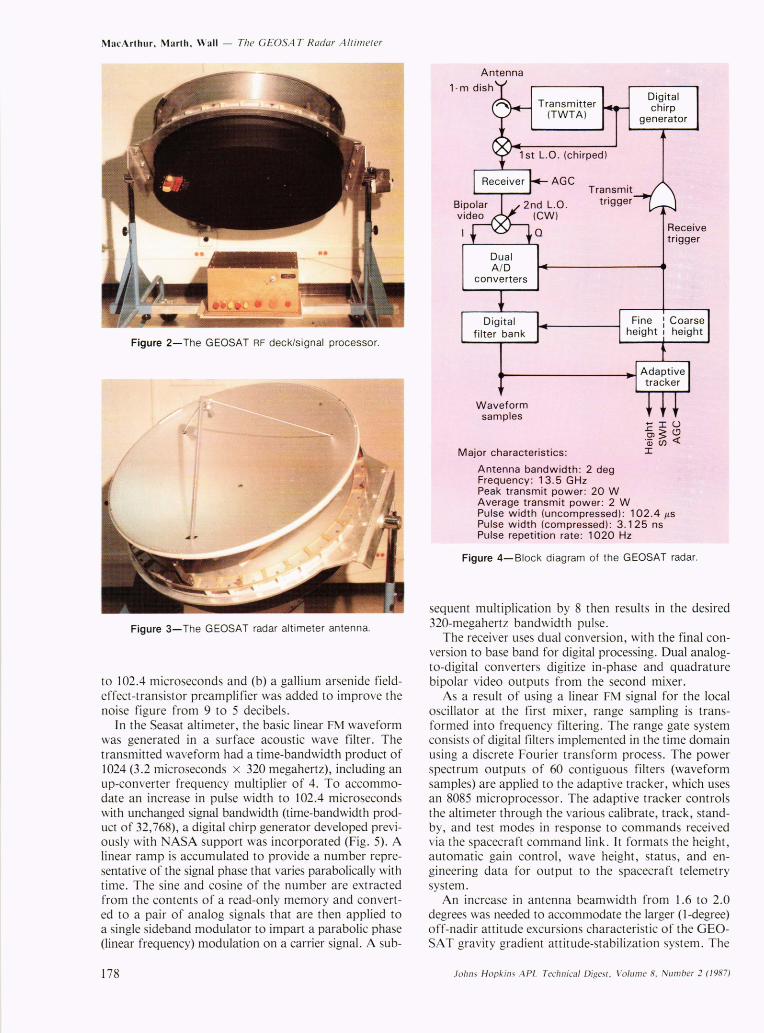
Figure 4 is a simplified block diagram of the altimeter. The system generates a linear FM (chirp) pulse waveform for transmission by a traveling wave tube amplifier. The 2-kilowatt amplifier used on Seasat and GEOS-3 gave evidence of not being able to support more than a few thousand hours of operation. Therefore, an existing 20-watt amplifier, space qualified and in production for the Landsat program, was selected for GEOSAT. Two design changes were made to compensate for the reduction in transmit power from 2 kilowatts to 20 watts: (a) the uncompressed pulse width was increased from 3.2
Table 1-Characteristics of the G EO SAT radar altimeter.
Waveform: Type Center frequency Pulse width Bandwidth Interpulse period Generation
Transmitter: Type Peak power (RF)
Power consumption (28 volts DC bus)
Signal processor: A I D converters (2) Digital filters
(range gates) Height least significant bit Adaptive tracker
Telemetry outputs: Digital (serial)
Frame size
Frame rate Contents (words)
Analog
Linear FM pulse 13.5 gigahertz 102.4 microseconds 320 megahertz 980 microseconds Digital synthesis
Traveling wave tube 20 watts (minimum) 70 watts
4 bits + sign 63
0.7325 centimeter 8085 processor
850 bits (85, lO-bit words)
10 per second 16 science 63 waveform samples
(range gates) 4 model status 1 engineering channel ID 1 engineering data
(50 channel subcom.)
12 channels (conditioned by altimeter) 10 channels (temps) (conditioned by spacecraft)
Operation modes: Standby I and II Track (4 modes) Calibrate Test (7 modes)
Johns Hopkins A PL Technical Digest, Volume 8, N umber 2 (1 987)
Antenna: Type Gain Beamwidth
Receiver: Type
I-meter parabolic > 37.6 decibels 2.0 degrees
Dual conversion 500 megahertz (lst IF),
o hertz (2nd IF)
Automatic gain control o to 63 decibels (l-deci bel steps)
Inputs: Bus 24 to 33 volts DC
Frequency reference Commands
5 megahertz 8-pulse digital data
Weight: Signal processor RF section
Power requirements: Standby
(lO-bit parallel)
47 pounds 144 pounds
103 watts Track 146 watts
Envelope (inches): RF section 41.25 dia. x 11.5 high = 15,369
Antenna
cubic inches (less antenna)
41.25 dia. x 19.125 high = 25,559 cubic inches (including feed)
Signal processor 20 long x 13.5 wide x 10 high = 2700 cubic inches
177
MacArthur, Marth, Wall - The GEOSA T Radar A lliJlleler
Figure 2-The GEOSAT RF deck/signal processor.
Figure 3-The GEOSAT radar altimeter antenna.
to 102.4 microseconds and (b) a gallium arsenide fieldeffect-transistor preamplifier was added to improve the noise figure from 9 to 5 decibels.
In the Seasat altimeter, the basic linear FM waveform was generated in a surface acoustic wave filter. The transmitted waveform had a time-bandwidth product of 1024 (3.2 microseconds x 320 megahertz), including an up-converter frequency mUltiplier of 4. To accommodate an increase in pulse width to 102.4 microseconds with unchanged signal bandwidth (time-bandwidth product of 32,768), a digital chirp generator developed previously with NASA support was incorporated (Fig. 5). A linear ramp is accumulated to provide a number representative of the signal phase that varies parabolically with time. The sine and cosine of the number are extracted from the contents of a read-only memory and converted to a pair of analog signals that are then applied to a single sideband modulator to impart a parabolic phase (linear frequency) modulation on a carrier signal. A sub-
178
Dual AI D
converters
Waveform samples
Transmitter (TWTA)
AGe Transmit
trigger
Major characteristics :
Antenna bandwidth: 2 deg Frequency : 13.5 GHz Peak transmit power: 20 W Average t ransmit power : 2 W
Digital chirp
generator
Receive trigger
Pulse width (uncompressed): 102.4 J.l.S Pulse width (compressed): 3.125 ns Pulse repetition rate : 1020 Hz
Figure 4-Block diagram of the GEOSAT radar.
sequent multiplication by 8 then results in the desired 320-megahertz bandwidth pulse.
The receiver uses dual conversion, with the final conversion to base band for digital processing. Dual analogto-digital converters digitize in-phase and quadrature bipolar video outputs from the second mixer.
As a result of using a linear FM signal for the local oscillator at the first mixer, range sampling is transformed into frequency filtering. The range gate system consists of digital filters implemented in the time domain using a discrete Fourier transform process. The power spectrum outputs of 60 contiguous filters (waveform samples) are applied to the adaptive tracker, which uses an 8085 microprocessor. The adaptive tracker controls the altimeter through the various calibrate, track, standby, and test modes in response to commands received via the spacecraft command link. It formats the height, automatic gain control, wave height, status, and engineering data for output to the spacecraft telemetry system .
An increase in antenna beamwidth from 1.6 to 2.0 degrees was needed to accommodate the larger (I -degree) off-nadir attitude excursions characteristic of the GEOSAT gravity gradient attitude-stabilization system. The
Johns Hopkins APL Technica l Digesi, Volume 8, Number 2 (1987)
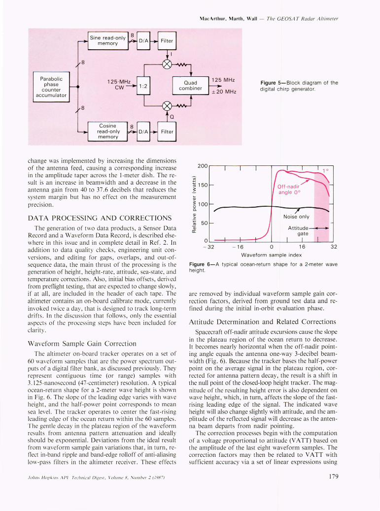
Parabolic phase
counter accumulator
Sine read-only memory
Cosine read-only memory
Filter
change was implemented by increasing the dimensions of the antenna feed, causing a corresponding increase in the amplitude taper across the I-meter dish. The result is an increase in beamwidth and a decrease in the antenna gain from 40 to 37.6 decibels that reduces the system margin but has no effect on the measurement precision.
DATA PROCESSING AND CORRECTIONS
The generation of two data products, a Sensor Data Record and a Waveform Data Record, is described elsewhere in this issue and in complete detail in Ref. 2. In addition to data qualit y checks, engineering unit conversions, and editing for gaps, overlaps, and out-ofsequence data, the main thrust of the processing is the generation of height , height-rate, attitude, sea-state, and temperature corrections. Also, initial bias offsets, derived from preflight testing, that are expected to change slowly, if at all, are included in the header of each tape. The altimeter contains an on-board calibrate mode, currently invoked twice a day, that is designed to track long-term drift s . In the discussion that follows, only the essential aspects of the processing steps have been included for clarity.
Waveform Sample Gain Correction
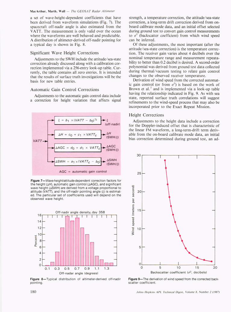
The altimeter on-board tracker operates on a set of 60 waveform samples that are the power spectrum outputs of a digital filter bank, as discussed previously. They represent contiguous time (or range) samples with 3. 125-nanosecond (47-centimeter) resolution. A typical ocean-return shape for a 2-meter wave height is shown in Fig. 6. The slope of the leading edge varies with wave height, and the half-power point corresponds to mean sea level. The tracker operates to center the fast-rising leading edge of the ocean return within the 60 samples. The gentle decay in the plateau region of the waveform results from antenna pattern attenuation and ideally should be exponential. Deviations from the ideal result from waveform sample gain variations that, in turn, reflect in-band ripple and band-edge rolloff of anti-aliasing low-pass filters in the altimeter receiver. These effects
JOhIlS H opkins APL Technical Digesr. \ 'olume 8. Number 2 (198 7)
MacArthur, Marth, Wall - The GEOSA TRadal' A /fill/ efer
Figure 5-Block diagram of the digital chirp generator.
200~--~--~--~----r---~--~---'----'
(J)
~ 150 ~
Q)
~ 100 0. Q)
> .~ 50 Q) a:
O~~~~~~~~ __ ~~ __ ~ __ ~ - 32 - 16 0 16 32
Waveform sample index
Figure 6-A typical ocean-return shape for a 2-meter wave height.
are removed by individual waveform sample gain correction factors, derived from ground test data and refined during the initial in-orbit evaluation phase.
Attitude Determination and Related Corrections
Spacecraft off-nadir attitude excursions cause the slope in the plateau region of the ocean return to decrease. It becomes nearly horizontal when the off-nadir pointing angle equals the antenna one-way 3-decibel beamwidth (Fig. 6). Because the tracker bases the half-power point on the average signal in the plateau region, corrected for antenna pattern decay, the result is a shift in the null point of the closed-loop height tracker. The magnitude of the resulting height error is also dependent on wave height, which, in turn, affects the slope of the fastrising leading edge of the signal. The indicated wave height will also change slightly with attitude, and the amplitude of the reflected signal will decrease as the antenna beam departs from nadir pointing.
The correction processes begin with the computation of a voltage proportional to attitude (V A TT) based on the amplitude of the last eight waveform samples. The correction factors may then be related to V A TT with sufficient accuracy via a set of linear expressions using
179
MacArthur, Marth, Wall - The GEOSA T Radar A ltimeter
a set of wave-height-dependent coefficients that have been derived from waveform simulations (Fig. 7). The spacecraft off-nadir angle is also estimated from the V A IT. The measurement is only valid over the ocean where the waveforms are well behaved and predictable. A distribution of altimeter-derived off-nadir pointing for a typical day is shown in Fig. 8.
Significant Wave Height Corrections
Adjustments to the SWH include the attitude/ sea-state correction already discussed along with a calibration correction implemented via a 256-entry look-up table. Currently, the table contains all zero entries. It is intended that the results of surface truth investigations will be the basis for new table entries.
Automatic Gain Control Corrections
Adjustments to the automatic gain control data include a correction for height variation that affects signal
VATT
tJ.H = Co + c1 x VATTc
tJ.AGC dO + d1 x VA TTc
tJ.SWH = a1 x (VATTc - bO)
~ (off-nadir)
tJ.H (SWH/O
tJ.AGC ( SWH/~ )
tJ.SWH ( SWH/~ )
AGC = automatic ga in control
Figure 7-Wave-height/attitude·dependent correction factors for the height (tJ.H) , automatic gain control (tJ.AGC), and significant wave height (tJ.SWH) are derived from a voltage proportional to attitude (VATT), and the off·nadir pointing angle (~) is estimat· ed. The particular set of coefficients used will depend on the observed wave height.
Off-nadir angle density, day 358 16~~~~~--~~~~~~--r-~~~~
14
12
.... 10 c::
~ 8 Q)
CL 6
4
2
O~~~~w-~~~~~u-~~~~~~~
0.10.30.50.70.91.1 1.3
Off-nadar angle (degrees)
Figure 8-Typical distribution of altimeter-derived off-nadir pointing .
180
strength, a temperature correction, the attitude/ sea-state correction, a long-term drift correction derived from onboard calibrate mode data, and an initial offset selected during ground test to convert gain control measurements to aD (backscatter coefficient) from which wind speed can be inferred.
Of these adjustments, the most important (after the attitude/ sea-state correction) is the temperature correction. The receiver gain varies about 4 decibels over the nominal temperature range and measurement repeatability to better than 0.2 decibel is desired. A second-order polynomial was derived from ground test data collected during thermal/vacuum testing to relate gain control changes to the observed receiver temperature.
Derivation of wind speed from the corrected automatic gain control (or from aD) is based on the work of Brown et al. 3 and is implemented via a look-up table having the relationship indicated in Fig. 9. As with sea state, reported surface truth correlations will suggest refinements to the wind-speed process that may also be incorporated prior to the Exact Repeat Mission.
Height Corrections
Adjustments to the height data include a correction for the Doppler-induced offset that is characteristic of the linear FM waveform, a long-term-drift term derivable from the on-board calibrate mode data, an initial bias correction determined during ground test, an ad-
30r-------.--------.--------.-------~
25
=0 c:: 0 20 u Q) (/)
a; a. ~ ~ 15 Q)
E 'D Q) Q)
a. (/)
'D 10 c::
~
5
O~ ______ ~ ______ ~ ________ ~ ______ ~ o 5 10 15 20
Backscatter coefficient (00 , decibels)
Figure 9-The derivation of wind speed from the corrected backscatter coefficient.
Johns Hopkins APL Technical Digesl, Volume 8, Number 2 (/987)

justment to reference the altimeter height measurement to the center of gravity of the spacecraft, and the attitude/ sea-state correction already discussed. The validity of these adjustments is not as readily assessable via surface truth correlations as is that of the wave height and gain control/wind-speed data. The long-term drift of the height measurement can be monitored during the signal injection phase of the on-board calibrate mode. A sample of the transmitted pulse is coupled into the receiver, processed through the system, and tracked as a point target. The result is shown in Fig. 10. With the exception of the anomalies that occur during the full sun periods (which reflect calibrate mode artifacts), the drift has been negligible, i.e., less than I centimeter. A conversion from time domain to frequency domain processing at an early point in the signal flow, along with digital frequency analysis, results in a system that is inherently free from drift.
The precision of the height measurement is also of interest. Ground test data have established that the altimeter noise level approaches 2 centimeters at low wave height for I-second averaging. Data spans of tens of seconds are required to make that measurement. To perform an equivalent evaluation in orbit would involve a data span of over 100 kilometers on the surface. Within the span, small-scale geoidal or oceanographic features and possibly atmospheric effects will typically result in an observed height variability that prevents centimeterlevel instrument precision from being verified. Instead, in-orbit performance has been evaluated by computing the standard deviation about a linear fit to IO-sample (I-second) sets of height data, repeating this for 10 consecutive sets, and averaging the results. In this case, only the surface variability over a much shorter I-second (7-kilometer) span will affect the measurement. It happens that for the tracking-filter time constant used (0.25 second), the standard deviation about a fit to 10 samples is nearly the same as the standard deviation of the average of 10 samples. The agreement between ground test data for I-second averages and the in-orbit data com-
Joh ns Hopkins APL Technica l Digesl, Volum e 8, Num ber 2 (198 7)
MacArthur, Marth, Wall - The GEOSA T Radar A ltimeter
91~----~-----.------.------,-----.
90 E u 89
E 88 Cl
~ 87
860
Calibrate mode step 30
100 200 500 Days from turn-on
Figure 10-Long-term height drift as monitored by an in-flight calibration mode has been less than 1 centimeter. The negative peaks are anomalies that occur during periods of full sun .
puted as described is quite good and, in either case, is close to theoretical predictions.
GEOSA T ALTIMETER PERFORMANCE SUMMARY
In support of the primary geodesy mission, an altimeter height precision of 3.5 centimeters for a 2-meter SWH has been demonstrated during ground testing and in-orbit operation.
The wave height and wind speed accuracies achieved by the altimeter are the subject of ongoing investigations (see the article by Dobson et aI., this issue). The available results indicate that the desired accuracies of 10 percent or 0.5 meter for wave height and 1.8 meters per second for wind speed are being realized.
The GEOSA T altimeter continues to operate and has exceeded the design life requirement of 18 months.
REFERENCES
I W. E. Frain, S. C. Jones, C. C. Kilgus, and J. L. MacArthur, " The Navy GEOSAT Mission Radar Altimeter Satellite Program , Monitoring Earth's Ocean, Land and Atmosphere from Space-Sensors, Systems and Applications," Prog. Astronaut. Aeronaut. 97, 440-463 (1985).
2 GEOSAT-A Data Users/Ground System Interface Control Document (ICD) , JH UlAPL 7292-9510 Rev. I (1985) .
3 G . S. Brown, H . R. Stanley, and N. A . Roy, "The Wind-Speed Measurement Capability of Spaceborne Radar Altimeters," IEEE 1. Oceanic Eng. OEAi, 59-63 (1982) .
181