Embed Size (px)
Citation preview

The geometric description - SDO_GEOMETRY data type1
With Spatial, the geometric description of a spatial object is stored: 1) in a single row; 2) in a single column of object type SDO_GEOMETRY 3) in a user-defined table4) where all geometry share the same coordinate system (SDO_SRID attribute).Any table that has a column of type SDO_GEOMETRY must have another column, or set of columns, that defines a unique primary key for that table. Tables of this sort are sometimes referred to as spatial tables or spatial geometry tables.
1 http://gerardnico.com/wiki/oracle_spatial/geometry
Spatial tableNUM GEOMETRY NAME
SDO_GEOMETRY data type

SDO_GEOMETRY data type conceptual model2

SDO_GTYPE
SDO_SRID
SDO_POINT
SDO_ELEM_INFO--------------------------------------SDO_STARTING_OFFSET
SDO_ETYPESDO_INTERPRETATION
SDO_ORDINATES----------------------X1,Y1,X2,Y2, ...
SDO_GEOMETRY data type and its elements (standard Geometry Object Model for the OGIS Simple Features for SQL)2
create type SDO_GEOMETRY as object( SDO_GTYPE number, SDO_SRID number, SDO_POINT SDO_POINT_TYPE, SDO_ELEM_INFO SDO_ELEM_INFO_ARRAY, SDO_ORDINATES SDO_ORDINATE_ARRAY);
create type SDO_POINT_TYPE as object( X number, Y number, Z number);
create type SDO_ELEM_INFO_ARRAY as varray(1048576) of number;
create type SDO_ORDINATE_ARRAY as varray(1048576) of number;
2 http://gerardnico.com/wiki/oracle_spatial/geometry
3

SDO_GTYPE
SDO_SRID
SDO_POINT
SDO_ELEM_INFO--------------------------------------SDO_STARTING_OFFSET
SDO_ETYPESDO_INTERPRETATION
SDO_ORDINATES----------------------X1,Y1,X2,Y2, ...
SDO_GTYPE element (geometry type)
The SDO_GTYPE attribute indicates the type of the geometry and is 4 digits
in the format dltt, where: 1) d identifies the number of dimensions (2, 3, or 4);2) l identifies the linear referencing measure dimension for a three-dimensional linear referencing system (LRS) geometry;3) tt identifies the geometry type (00 through 07, with 08 through 99 reserved for future use).The number of dimensions reflects the number of ordinates used to represent each vertex. Points and lines are considered two-dimensional objects.
In any given layer (column), all geometries must have the same number of dimensions. For example, you cannot mix two-dimensional and three-dimensional data in the same layer (column). The following methods are available for returning the individual dltt components of the SDO_GTYPE for a geometry object: 1) Get_Dims; 2) Get_LRS_Dim;3) Get_Gtype.
4

Value Geometry Type Description dl00 UNKNOWN_GEOMETRY Spatial ignores this geometry dl01 POINT Geometry contains one point
dl02 LINE or CURVE
Geometry contains one line string that can contain straight or circular arc segments, or both. (LINE and CURVE are synonymous in this context.)
dl03 POLYGON
Geometry contains one polygon with or without holes. For a polygon with holes, enter the exterior boundary first, followed by any interior boundaries.
dl04 COLLECTION Geometry is a heterogeneous collection of elements. COLLECTION is a superset that includes all other types.
dl05 MULTIPOINT Geometry has one or more points. (MULTIPOINT is a superset of POINT.)
dl06 MULTILINE or MULTICURVE
Geometry has one or more line strings. (MULTILINE and MULTICURVE are synonymous in this context, and each is a superset of both LINE and CURVE.)
dl07 MULTIPOLYGON
Geometry can have multiple, disjoint polygons (more than one exterior boundary). (MULTIPOLYGON is a superset of POLYGON.)
DL08 SOLID
Geometry consists of multiple surfaces and is completely enclosed in a three-dimensional space. Can be a cuboid or a frustum.
DL09 MULTISOLIDGeometry can have multiple, disjoint solids (more than one exterior boundary). (MULTISOLID is a superset of SOLID.)
5

SDO_GTYPE
DLTT, whereD – number of dimensions;L – for Linear Referencing System) TT – from 00 to 09 geometry types.
SDO_GTYPE=2003 2 dimensions polygon (3)
6

SDO_GTYPE
SDO_SRID
SDO_POINT
SDO_ELEM_INFO--------------------------------------SDO_STARTING_OFFSET
SDO_ETYPESDO_INTERPRETATION
SDO_ORDINATES----------------------X1,Y1,X2,Y2, ...
SDO_SRID elementThe SDO_SRID attribute can be used to identify a coordinate system (spatial reference system) to be associated with the geometry. If SDO_SRID is null, no coordinate system is associated with the geometry. If SDO_SRID is not null, it must contain a value from the SRID column of the SDO_COORD_REF_SYS table, and this value must be inserted into the SRID column of the USER_SDO_GEOM_METADATA view. All geometries in a geometry column must have the same SDO_SRID value.
SDO_GTYPE = 2003 2 dimensions polygon (3)SDO_SRID = NULL
7
SDO_GTYPE
SDO_SRID
SDO_POINT
SDO_ELEM_INFO--------------------------------------SDO_STARTING_OFFSET
SDO_ETYPESDO_INTERPRETATION
SDO_ORDINATES----------------------X1,Y1,X2,Y2, ...
SDO_POINT element (point coordinates)
The SDO_POINT attribute is defined using the SDO_POINT_TYPE object type, which has the attributes X, Y, and Z, all of type NUMBER. If the SDO_ELEM_INFO and SDO_ORDINATES arrays are both null, and the SDO_POINT attribute is non-null, then the X and Y values are considered to be the coordinates for a point geometry. Otherwise, the SDO_POINT attribute is ignored by Spatial. You should store point geometries in the SDO_POINT attribute for optimal storage; and if you have only point geometries in a layer, it is strongly recommended that you store the point geometries in the SDO_POINT attribute.
create type SDO_POINT_TYPE as object( X number, Y number, Z number);
8

Geometry – point (X, Y)
SDO_GTYPE = 2001 2 dimension point (1) SDO_SRID = NULLSDO_POINT = SDO_POINT_TYPE(12, 14, NULL) coordinates of point
insert into LAYER1 values (90, SDO_GEOMETRY(2001, NULL,SDO_POINT_TYPE(12, 14, NULL), NULL, NULL), '1. point');
select *from LAYER1 c where c.GEOMETRY.SDO_POINT.X = 12;
G_NUM GEOMETRY(SDO_GTYPE, SDO_SRID, SDO_POINT(X, Y, Z), SDO_ELEM_INFO, SDO_ORDINATES G_NOS---------------------------------------------------------------------------------------------------------- 90 SDO_GEOMETRY(2001, NULL, SDO_POINT_TYPE(12, 14, NULL), NULL, NULL), '1.point')
9

SDO_GTYPE
SDO_SRID
SDO_POINT
SDO_ELEM_INFO--------------------------------------SDO_STARTING_OFFSET
SDO_ETYPESDO_INTERPRETATION
SDO_ORDINATES----------------------X1,Y1,X2,Y2, ...
SDO_ORDINATES element (coordinates)
The SDO_ORDINATES attribute is defined using a varying length array (1048576) of NUMBER type that stores the coordinate values that make up the boundary of a spatial object. This array must always be used in conjunction with the SDO_ELEM_INFO varying length array. The values in the array are ordered by dimension:
1) a polygon whose boundary has four two-dimensional points is stored as {X1, Y1, X2, Y2, X3, Y3, X4, Y4, X1, Y1}.
2) if the points are three-dimensional, then they are stored as {X1, Y1, Z1, X2, Y2, Z2, X3, Y3, Z3, X4, Y4, Z4, X1, Y1, Z1}.
The values in the SDO_ORDINATES array must all be valid and non-null. There are no special values used to delimit elements in a multielement geometry. The start and end points for the sequence describing a specific element are determined by the STARTING_OFFSET values for that element and the next element in the SDO_ELEM_INFO array. The offset values start at 1. SDO_ORDINATES(1) is the first ordinate of the first point of the first element.
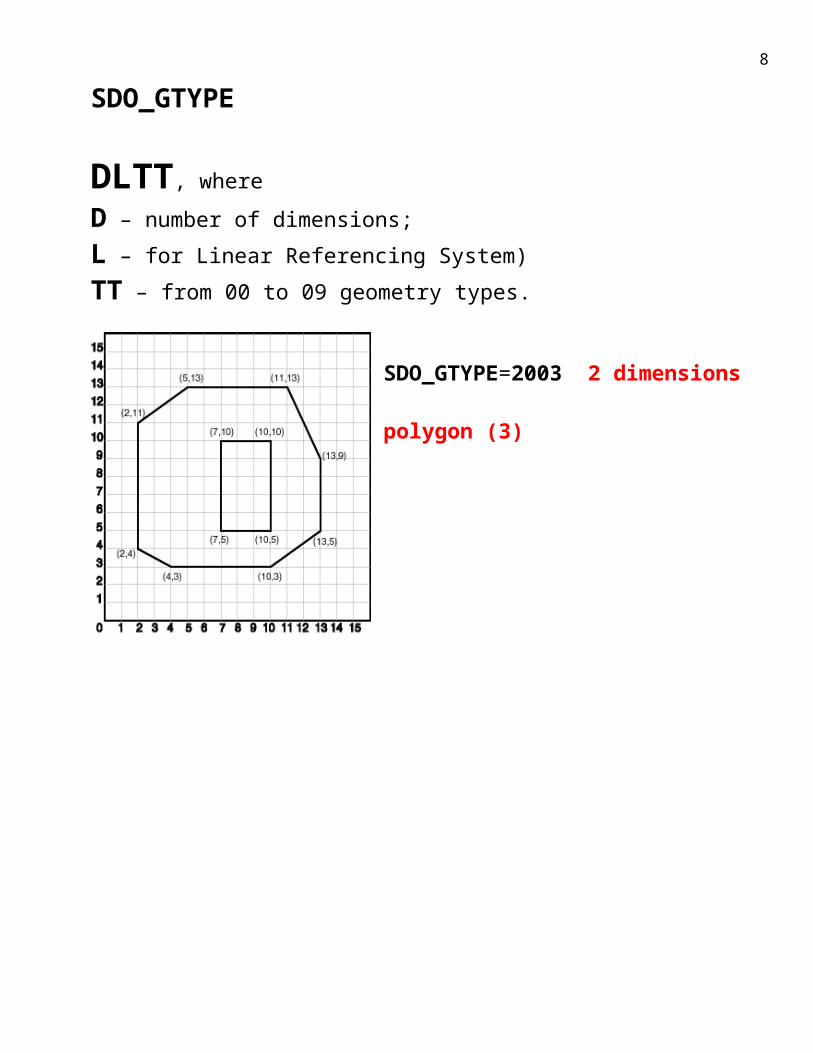
. . . SDO_ORDINATES SDO_ORDINATE_ARRAY,. . .
create type SDO_ORDINATE_ARRAY as varray(1048576) of number;Divu dimensiju ģeometrijām:{X1, Y1, X2, Y2, X3, Y3, X4, Y4, X1, Y1}. Triju dimensiju ģeometrijām:{X1, Y1, Z1, X2, Y2, Z2, X3, Y3, Z3, X4, Y4, Z4, X1, Y1, Z1}.
10

SDO_GTYPE = 2003 2 dimension polygon (3)SDO_SRID = NULLSDO_POINT = NULLSDO_ELEM_INFO = (1,1003,1, 19,2003,1)1003 – simple outer poligon2003 – inner polygon19 – starting coordinate (inner polygon) SDO_ORDINATES = (2,4, 4,3, 10,3, 13,5, 13,9, 11,13, 5,13, 2,11, 2,4, 7,5, 7,10, 10,10, 10,5, 7,5).
First must be defined exterior polygon
11

SDO_GTYPE
SDO_SRID
SDO_POINT
SDO_ELEM_INFO--------------------------------------SDO_STARTING_OFFSET
SDO_ETYPESDO_INTERPRETATION
SDO_ORDINATES----------------------X1,Y1,X2,Y2, ...
SDO_ELEM_INFO element (interpretation of coordinates)
This attribute lets you know how to interpret the ordinates stored in the SDO_ORDINATES attribute. The SDO_ELEM_INFO attribute is defined using a varying length array of numbers with triplets.
SDO_STARTING_OFFSETIndicates the offset within the SDO_ORDINATES array where the first ordinate for this element is stored. Offset values start at 1 and not at 0. Thus, the first ordinate for the first element will be at SDO_GEOMETRY.SDO_ORDINATES(1). If there is a second element, its first ordinate will be at SDO_GEOMETRY.SDO_ORDINATES(n), where n reflects the position within the SDO_ORDINATE_ARRAY definition (for example, 19 for the 19th number.
12

SDO_ETYPE element (indicates the type of the element)
Simple elements (SDO_ETYPE values 1, 2, 1003, and 2003)
They are defined by a single triplet entry in the SDO_ELEM_INFO array. For SDO_ETYPE values 1003 and 2003, the first digit indicates exterior (1) or interior (2): 1) 1003: exterior polygon ring (must be specified in counterclockwise order);2) 2003: interior polygon ring (must be specified in clockwise order).You cannot mix 1-digit and 4-digit SDO_ETYPE values in a single geometry. If you use 4-digit SDO_ETYPE values, you must use 4-digit SDO_GTYPE values.
Compound elements (SDO_ETYPE values 4, 1005, and 2005)
They contain at least one header triplet with a series of triplet values that belong to the compound element. For SDO_ETYPE values 1005 and 2005, the first digit indicates exterior (1) or interior (2): 1) 1005: exterior polygon ring (must be specified in counterclockwise order)2) 2005: interior polygon ring (must be specified in clockwise order)You cannot mix 1-digit and 4-digit SDO_ETYPE values in a single geometry. If you use 4-digit SDO_ETYPE values, you must use 4-digit SDO_GTYPE values. The elements of a compound element are contiguous. The last point of a subelement in a compound element is the first point of the next subelement. The point is not repeated.
13

SDO_INTERPRETATION
If SDO_ETYPE is a compound element (4, 1005, or 2005), this field specifies how many subsequent triplet values are part of the element.
If the SDO_ETYPE is not a compound element (1, 2, 1003, or 2003), the interpretation attribute determines how the sequence of ordinates for this element is interpreted. For example, a line string or polygon boundary may be made up of a sequence of connected straight line segments or circular arcs.
If a geometry consists of more than one element, then the last ordinate for an element is always one less than the starting offset for the next element. The last element in the geometry is described by the ordinates from its starting offset to the end of the SDO_ORDINATES varying length array.
For compound elements (SDO_ETYPE values 4, 1005, or 2005), a set of n triplets (one for each subelement) is used to describe the element. It is important to remember that subelements of a compound element are contiguous. The last point of a subelement is the first point of the next subelement. For subelements 1 through n-1, the end point of one subelement is the same as the starting point of the next subelement. The starting point for subelements 2…n-2 is the same as the end point of subelement 1…n-1. The last ordinate of subelement n is either the starting offset minus 1 of the next element in the geometry, or the last ordinate in the SDO_ORDINATES varying length array.
14
SDO_ETYPE and SDO_INTERPRETATION elemets values
SDO_ETYPE
SDO_INTERPRETATION Explanations
1 1 Point type.1 0 Orientation for an oriented point. 1 n > 1 Point cluster with n points.2 1 Line string whose vertices are connected by straight
line segments.2 2 Line string made up of a connected sequence of
circular arcs.Each circular arc is described using three coordinates: the start point of the arc, any point on the arc, and the end point of the arc. The coordinates for a point designating the end of one arc and the start of the next arc are not repeated. For example, five coordinates are used to describe a line string made up of two connected circular arcs. Points 1, 2, and 3 define the first arc, and points 3, 4, and 5 define the second arc, where point 3 is only stored once.
1003 or 2003
1 Simple polygon whose vertices are connected by straight line segments. You must specify a point for each vertex; and the last point specified must be exactly the same point as the first (within the tolerance value), to close the polygon. For example, for a 4-sided polygon, specify 5 points, with point 5 the same as point 1.
1003 or 2003
2 Polygon made up of a connected sequence of circular arcs that closes on itself. The end point of the last arc is the same as the start point of the first arc.Each circular arc is described using three coordinates: the start point of the arc, any point on the arc, and the end point of the arc. The coordinates for a point designating the end of one arc and the start of the next arc are not repeated. For example, five coordinates are
15

SDO_ETYPE
SDO_INTERPRETATION Explanations
used to describe a polygon made up of two connected circular arcs. Points 1, 2, and 3 define the first arc, and points 3, 4, and 5 define the second arc. The coordinates for points 1 and 5 must be the same (tolerance is not considered), and point 3 is not repeated.
1003 or 2003
3 Rectangle type (sometimes called optimized rectangle). A bounding rectangle such that only two points, the lower-left and the upper-right, are required to describe it. The rectangle type can be used with geodetic or non-geodetic data. However, with geodetic data, use this type only to create a query window (not for storing objects in the database).
1003 or 2003
4 Circle type. Described by three distinct non-colinear points, all on the circumference of the circle.
4 n > 1 Compound line string with some vertices connected by straight line segments and some by circular arcs. The value n in the Interpretation column specifies the number of contiguous subelements that make up the line string.The next n triplets in the SDO_ELEM_INFO array describe each of these subelements. The subelements can only be of SDO_ETYPE 2. The last point of a subelement is the first point of the next subelement, and must not be repeated.
1005 or 2005
n > 1 Compound polygon with some vertices connected by straight line segments and some by circular arcs. The value n in the Interpretation column specifies the number of contiguous subelements that make up the polygon.The next n triplets in the SDO_ELEM_INFO array describe each of these subelements. The subelements can only be of SDO_ETYPE 2. The end point of a subelement is the start point of the next subelement, and it must not be repeated. The start and end points of the polygon must be exactly the same point (tolerance is ignored).
16

SDO_ETYPE
SDO_INTERPRETATION Explanations
1006 or 2006
n > 1 Surface consisting of one or more polygons, with each edge shared by no more than two polygons. A surface contains an area but not a volume. The value n in the Interpretation column specifies the number of polygons that make up the surface.The next n triplets in the SDO_ELEM_INFO array describe each of these polygon subelements.A surface can be two-dimensional or three-dimensional..
1007 n = 1 or 3 Solid consisting of multiple surfaces that are completely enclosed in a three-dimensional space, so that the solid has an interior volume. A solid element can have one exterior surface defined by the 1006 elements and zero or more interior boundaries defined by the 2006 elements. The value n in the Interpretation column must be 1 or 3.Subsequent triplets in the SDO_ELEM_INFO array describe the exterior 1006 and optional interior 2006 surfaces that make up the solid element.If n is 3, the solid is an optimized box, such that only two three-dimensional points are required to define it: one with minimum values for the box in the X, Y, and Z dimensions and another with maximum values for the box in the X, Y, and Z dimensions. For example:SDO_GEOMETRY(3008, NULL, NULL, SDO_ELEM_INFO_ARRAY(1,1007,3), SDO_ORDINATE_ARRAY(1,1,1, 3,3,3))
17

Rectangle
SDO_GTYPE = 2003 2 dimension polygon (3) SDO_SRID = NULLSDO_POINT = NULLSDO_ELEM_INFO = (1, 1003, 3)
SDO_STARTING_OFFSET 1 first coordinateSDO_ETYPE 1003 simple polygonSDO_INTERPRETATION 3 rectangle
SDO_ORDINATES = (1,1, 5,7) Left lower corner and right upper corner coordinates
insert into GEOMETRIJAS values(21, 'rectangle', SDO_GEOMETRY(2003, NULL, NULL,SDO_ELEM_INFO_ARRAY(1,1003,3),SDO_ORDINATE_ARRAY(1,1, 5,7) ));

Polygon with hole
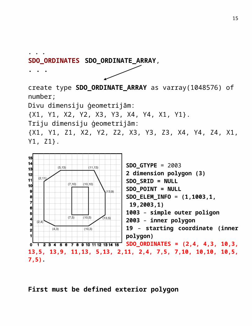
SDO_GTYPE = 2003 2 dimension polygon (3)SDO_SRID = NULLSDO_POINT = NULLSDO_ELEM_INFO = (1,1003,1, 19,2003,1)1 – exterior polygon first coordinate1003 – exterior polygon1 – straight lines use
19 – interior polygon first coordinate 2003 – exterior polygon 1 – straight lines use
SDO_ORDINATES = (2,4, 4,3, 10,3, 13,5, 13,9, 11,13, 5,13, 2,11, 2,4, 7,5, 7,10, 10,10, 10,5, 7,5).
19

Point cluster with 5 pointsSDO_ELEM_INFO = (1, 1, 5)
SDO_STARTING_OFFSET 1 first coordinateSDO_ETYPE 1 pointSDO_INTERPRETATION 5 five points
20

Line string with straight line segmentsSDO_ELEM_INFO = (1, 2, 1)
SDO_STARTING_OFFSET 1 first coordinateSDO_ETYPE 2 line stringSDO_INTERPRETATION 1 straight line segments
Line string with arcuate segmentsSDO_ELEM_INFO = (1, 2, 2)
SDO_STARTING_OFFSET 1 first coordinateSDO_ETYPE 2 line string
SDO_INTERPRETATION 2 sequence of circular arcs
21

Polygon made up of a connected sequence of circular arcsSDO_ELEM_INFO = (1, 1003, 2)
SDO_STARTING_OFFSET 1 first coordinateSDO_ETYPE 1003 simple polygon
SDO_INTERPRETATION 2 sequence of circular arcs
22

Circle typeSDO_ELEM_INFO = (1, 1003, 4)
SDO_STARTING_OFFSET 1 first coordinateSDO_ETYPE 1003 simple polygon
SDO_INTERPRETATION 4 circle type
23

Compound line string with some vertices connected by straight line segments and some by circular arcs 1.segment 2. segment 3.segmentSDO_ELEM_INFO = (1, 4, 3, 1, 2, 1, 5, 2, 2, 13, 2, 1)
SDO_STARTING_OFFSET 1 first coordinateSDO_ETYPE 4 compaund line
SDO_INTERPRETATION 3 segments
Compound line string with some vertices connected by straight line segments and some by circular arcs. The value n in the Interpretation column specifies the number of contiguous subelements that make up the line string.The next n triplets in the SDO_ELEM_INFO array describe each of these subelements. The subelements can only be of SDO_ETYPE 2. The last point of a subelement is the first point of the next subelement, and must not be repeated.
24

Compound polygon with some vertices connected by straight line segments and some by circular arcs 1.segment 2. segment SDO_ELEM_INFO = (1, 1005, 2, 1, 2, 1, 5, 2, 2)
SDO_STARTING_OFFSET 1 first coordinateSDO_ETYPE 1005 compaund polygon
SDO_INTERPRETATION 2 segments
Compound polygon with some vertices connected by straight line segments and some by circular arcs. The value n in the Interpretation column specifies the number of contiguous subelements that make up the polygon.The next n triplets in the SDO_ELEM_INFO array describe each of these subelements. The subelements can only be of SDO_ETYPE 2. The end point of a subelement is the start point of the next subelement, and it must not be repeated. The start and end points of the polygon must be exactly the same point (tolerance is ignored).
25

2 elements jointly 1.element 2. element SDO_ELEM_INFO = (1, 1003, 1, 13, 1003, 4)
SDO_STARTING_OFFSET 1 first coordinateSDO_ETYPE 1003 simple polygon
SDO_INTERPRETATION 1 stright lines 4 ring
26

Polygon with hole (void)
1.element 2. element SDO_ELEM_INFO = (1, 1003, 1, 13, 2003, 3)
SDO_STARTING_OFFSET 1 first coordinateSDO_ETYPE 1003 first simple polygon 2003 second
SDO_INTERPRETATION 1 stright lines 3 rectangle
27

Compound polygon with some vertices connected by straight line segments and some by circular arcs
1.element 1. segment 2. segment 2. elementSDO_ELEM_INFO = (1, 1005, 2, 1, 2, 1 7, 2, 2 17, 2003, 3)
SDO_STARTING_OFFSET 1 first coordinateSDO_ETYPE 1005 first compaund polygon 2003 second
SDO_INTERPRETATION 2 different lines 3 rectangle
Compound polygon with some vertices connected by straight line segments and some by circular arcs. The value n in the Interpretation column specifies the number of contiguous subelements that make up the polygon.The next n triplets in the SDO_ELEM_INFO array describe each of these subelements. The subelements can only be of SDO_ETYPE 2. The end point of a subelement is the start point of the next subelement, and it must not be repeated. The start and end points of the polygon must be exactly the same point (tolerance is ignored).
28

Type 0 (Zero) Element
Type 0 (zero) elements are used to model geometry types that are not supported by Oracle Spatial, such as curves and splines. A type 0 element has an SDO_ETYPE value of 0. Type 0 elements are not indexed by Oracle Spatial, and they are ignored by Spatial functions and procedures.Geometries with type 0 elements must contain at least one nonzero element, that is, an element with an SDO_ETYPE value that is not 0. The nonzero element should be an approximation of the unsupported geometry, and therefore it must have both:- An SDO_ETYPE value associated with a geometry type supported by Spatial- An SDO_INTERPRETATION value that is valid for the SDO_ETYPE value.(The SDO_INTERPRETATION value for the type 0 element can be any numeric value, and applications are responsible for determining the validity and significance of the value.)The nonzero element is indexed by Spatial, and it will be returned by the spatial index.The SDO_GTYPE value for a geometry containing a type 0 element must be set to the value for the geometry type of the nonzero element.Figure shows a geometry with two elements: a curve (unsupported geometry) and a rectangle (the nonzero element) that approximates the curve. The curve looks like the letter S, and the rectangle is represented by the dashed line.
29

The SDO_GTYPE value for the geometry is 2003 (for a two-dimensional polygon).The SDO_ELEM_INFO array contains two triplets for this compound line string. For example, the triplets might be {(1,0,57), (11,1003,3)}. That is:Ordinate Starting Offset (SDO_STARTING_OFFSET)
Element Type (SDO_ETYPE)
Interpretation (SDO_INTERPRETATION)
1 0 5711 1003 3
In this example:- The type 0 element has an SDO_ETYPE value of 0.- The nonzero element (rectangle) has an SDO_ETYPE value of 1003, indicating an exterior polygon ring.- The nonzero element has an SDO_STARTING_OFFSET value of 11 because ordinate x6 is the eleventh ordinate in the geometry.- The type 0 element has an SDO_INTERPRETATION value whose significance is application-specific. In this example, the SDO_INTERPRETATION value is 57.- The nonzero element has an SDO_INTERPRETATION value that is valid for the SDO_ETYPE of 1003. In this example, the SDO_INTERPRETATION value is 3, indicating a rectangle defined by two points (lower-left and upper-right).Example shows a SQL statement that inserts the geometry with a type 0 element into the database. In the SDO_ORDINATE_ARRAY structure, the curve is defined by points (6,6), (12,6), (9,8), (6,10), and (12,10), and the rectangle is defined by points (6,4) and (12,12).
INSERT INTO cola_markets VALUES(13, 'type_zero_element_geom', SDO_GEOMETRY( 2003, -- two-dimensional polygon NULL, NULL, SDO_ELEM_INFO_ARRAY(1,0,57, 11,1003,3), -- 1st is type 0 element SDO_ORDINATE_ARRAY(6,6, 12,6, 9,8, 6,10, 12,10, 6,4, 12,12) ) );
30

Poligons ar caurumu (gredzens) (ne divi poligoni)
SDO_GTYPE = 2003 2 dimensiju poligons (3)SDO_SRID = NULLSDO_POINT = NULLSDO_ELEM_INFO = (1,1003,1, 19,2003,1)1003 – poligona ārējā kontūra2003 – poligona iekšējā kontūra19 – poligona iekšējās kontūras pirmās koordinātes kārtas numurs masīvā SDO_ORDINATES = (2,4, 4,3, 10,3, 13,5, 13,9, 11,13, 5,13, 2,11, 2,4, 7,5, 7,10, 10,10, 10,5, 7,5).
insert into GEOMETRIJAS values(6, SDO_GEOMETRY( 2003, -- divu dimensiju poligons NULL, NULL, SDO_ELEM_INFO_ARRAY(1,1003,1, 19,2003,1), -- poligons ar caurumu SDO_ORDINATE_ARRAY(2,4, 4,3, 10,3, 13,5, 13,9, 11,13, 5,13, 2,11, 2,4, 7,5, 7,10, 10,10, 10,5, 7,5) ), '1. gredzns' );
31

Salikta (compaund) līnija
SDO_GTYPE = 20022 dimensiju līniju segmenti (2) SDO_SRID = NULL.SDO_POINT = NULL.SDO_ELEM_INFO = (1,4,2, 1,2,1, 3,2,2).
1,4,2 – salikta līnija no diviem elementiem1,2,1 – taisnu līniju segments, koordinātes sākas ar pirmo pozīciju (1)3,2,2 – loks, koordinātes sākas ar 3 pozīciju
SDO_ORDINATES = (10,10, 10,14, 6,10, 14,10).
insert into GEOMETRIJAS values(11, SDO_GEOMETRY( 2002, NULL, NULL, SDO_ELEM_INFO_ARRAY(1,4,2, 1,2,1, 3,2,2), SDO_ORDINATE_ARRAY(10,10, 10,14, 6,10, 14,10) ), 'salikta līnija' );
32

Salikts (compaund) poligons
SDO_GTYPE = 2003 2 dimesiju poligonsSDO_SRID = NULLSDO_POINT = NULLSDO_ELEM_INFO = (1,1005,2, 1,2,1, 5,2,2)1,1005,2 – salikts poligons no 2 līniju segmentiem1,2,1 – pirmais segments taisnas līnijas un koordinātes sākas no pozīcijas 15,2,2 – loks, koordinātes sākas no pozīcijas 5SDO_ORDINATES = (6,10, 10,1, 14,10, 10,14, 6,10).
insert into GEOMETRIJAS values(12, SDO_GEOMETRY(2003, NULL, NULL,SDO_ELEM_INFO_ARRAY(1,1005,2, 1,2,1, 5,2,2), SDO_ORDINATE_ARRAY(6,10, 10,1, 14,10, 10,14, 6,10) ), 'salikts poligons');
33