Embed Size (px)
Citation preview

The G3FEW Multi-Band Antennaby E A Rule G3FEW (1487)
The search for the perfect antenna started with the birth of amateur radioand to my knowledge it hasn't yet been found ! All antennas are a compro-mise in one or more aspects, although of course one expects to get fairlyclose to the ideal.
Amateurs with large estates don't have to much of a problem getting adecent antenna installed, but we lesser mortals have to make do with whatwe have. In my case it's a garden of 50 ft. width by 60 ft. long with a fieldbacking on to it which I have permission to put a wire across. Manyamateurs have much less than this.
I decided to set some goals for my "perfect" antenna.1. Must cover at least five HF bands.2. Low SWR at the design frequencies.3. Not need an ATU.4. Have same radiation pattern on each band.5. Be easy to repeat the construction.6. Be adaptable for different locations.
The prototype.Using an antenna design program a number of different models were
tried to see which would come closest to my "perfect" antenna. It wasdecided to go for a full wave system fed a quarter wave in from one end. Thereasons for this choice will become clearer later on. In order to maintain thesame radiation pattern on each band, Traps would be used.
A prototype was constructed for the 10, 12, 15, and 17 metre bands.Traps were constructed using standard receiver type components and thesewere found suitable for QRP up to about 20 watts, enabling tests to becarried out.
The SWR was 1:1 on each band at the design frequency. It was thendecided to build Traps suitable for full legal power and this is whereproblem number one arose !
After two days searching the web and telephoning manufactures itbecame obvious that suitable capacitors were not readily available. I hadalso tried coaxial Traps, (more about these later). It soon became clear thata solution was needed for the capacitor problem. Some years ago I haddesigned a lowpass filter for transmitters using double side printed circuitboard for the capacitors, this was very successful and it was decided to trythis approach for the Traps. A visit to the local pcb manufacture resulted ina generous supply of double sided 1mm thickness Fibreglass off-cuts (somequite large). As the Traps would be wound on 40mm o/d tube 6.5cm long a
34

piece of pcb board was cut to 3.5cm x 6cm and checked on a bridge for itscapacity value. This was 96pf. Several pieces were cut and checked and allcame within the range 96 to 98pf. Consistent enough to design using 100pfas the design value (this was to allow a little extra capacitance for the endsand anchor points.
The new traps were inserted into the prototype antenna. Tests at 100watts continuous showed only a slight heating in the 28Mhz trap and somelesser heating in the 24 Mhz Traps. Under normal SSB and CW no heatingwas detected. No heating was detected at the lower frequencies.
Some contacts were made on 28 Mhz which confirmed that the Trapsbehaved well and no sign of flash over.
L C Traps.As traps are an important part of multi-band antenna systems, some
aspects of the various types may be of interest. There are two main featuresof using a trap. It can be used as an insulator at the design frequency or itcan be used as a loading device by operation at other frequencies.
Consider the dipole antenna of fig 1. This can be used on more than oneband, using one trap in each section. The first section operates on 40metres and the whole works on 80 metres. The Traps are tuned to 7.1Mhz.If the operating frequency is lower than the trap resonant frequency it actsas an inductance, if above, it acts as a capacitor. Inductive loading willelectrically lengthen the antenna and capacitance loading will electricallyshorten the antenna..
Showing current distribution for 7.1 and 3.7 Mhz in a trapped dipole.First section to the trap is 10.5 metres long and overall length is 18
metres. a reduction on 80 metres of 12% in length. The trap used a 100pfcapacitor. L == 5.025 microH. Because the trap is operating at 7.1 Mhz itacts as a high impedance (insulator) at that frequency as can be seen by the
trap Feed point trapTraps tuned to 7.1MHz.
C TTFig 1.
10.5m 10.5m 7.5m7.5m
35

current distribution. On 80 metres it acts as a loading coil reducing thewire length required.
The finished traps where given a good coat of Yacht varnish for weatherprotection. Changing the values of L or C in a trap will effect the final designconsiderably. One can not "just fit a trap" and expect good results. Ingeneral, the smaller the C means a larger L (to maintain resonance) and ashorter antenna wire length. In some quarters a value of 1pf per metrewavelength has been suggested for the capacitor value, however for ease ofconstruction I settled of a value of 100pf for all Traps and in practice thisproved to be satisfactory. The general view is shown below.
End viewshowing pcb
capacitormounted insideformer. also endanchor points.
Typical LC trap.The one shown
is for 10.1 MHz.turn spacing isadjusted forresonance.
pcb capacitor 3.5 x 6cm x 1mm. Note; copperon edges (both sides) istrimmed back from edge
to avoid flash-over.
Original trap usingreceiver components.
C = 150pf
Cutting the pcb boardI found the easy way was to scribe the place you want to cut. Clamp
the capacitor section in the jaws of a bench vice. Deeply score along thescribe line (both sides) using the vice jaws as a guide. Then a firm pushand pull of the unwanted section and a clean break will occur. Thismethod is quicker and cleaner than using a saw.
Cutting the waste pipe.I found this was best cut using a wood workers tenon saw, with the
waste pipe clamped in a bench vice.
36

Coax TrapsTraps constructed from coax are used by many amateurs, however they
operate in a different manner to LC Traps.The use of coaxial-cable to construct antenna traps was first described
in amateur literature in 1981. Coaxial-cable traps are inexpensive, easy toconstruct, stable with respect to temperature variation and capable ofoperation at surprisingly high power levels.
Coaxial-cable antenna traps are constructed by winding coaxial-cable ona circular former. The centre conductor of one end is soldered to the shieldof the other end, and the remaining centre conductor and shield connec-tions are connected to the antenna elements. The series-connected innerconductor and shield of the coiled coaxial-cable act like a bifilar winding,forming the trap inductance, while the same inner conductor and shield,separated by the coaxial-cable dielectric, serve as the trap capacitor.
The resultant parallel-resonant LC circuit exhibits a high impedance atthe resonant frequency of the trap and effectively disconnects everythingafter the trap from the previous section. Traps which are operating belowtheir resonant frequency function as loading coils and shorten the overallphysical length of the antenna. This shortening can be very large and forexample a half wave dipole covering 10, 12 or 17 metres the shorteningeffect can be so large that a "negative" element length would be required!
I have included construction details for those amateurs who want to trythem, but be prepared for a frustrating time in establishing the correctelement lengths !
I used a similar construction to the LCtype and can be seen in the photo's.
Tuning coaxial traps to resonance.Traps are normally tuned to resonance by adjusting the spacing between
turns. However with coax traps this can be difficult due to the "springiness"of the coax. A solution that I use is to make the traps natural frequencyslightly lower than required and to use a "shorted turn" to bring to thecorrect frequency. This is a well known way of increasing the frequency of a
37

tuned circuit. It was used for many years in broadcast receivers to adjustthe padding of oscillator circuits (used in the HRO receiver).
The single turn of copper wire (fitted at the braid end) can be seen in thephoto of the coax trap. This has no effect on the working of the trap apartfrom adjusting the frequency. The capacity is distributed along the length ofthe coax winding and coax traps do not operate in the same way as a LCtrap, they act more like a stub.
Element lengths are effected by many things, type of trap used, heightabove ground, nearby objects, etc.. Always start by getting the higherfrequencies correct first. Because each trap isolates the next lowerfrequency section, adjustments made there will not effect the previoushigher frequency section.
General.Traps should be adjusted to the exact frequency before connecting into
the antenna. This is best done by using a GDO held close to the coil. TheGDO should be calibrated against the station receiver.
It is very important that each trap is tuned to the same frequency as theprevious section of the antenna is designed for. Once final adjustment hasbeen made a good coat of Yacht varnish should be applied.
Coax traps should always be connected the same way round. I.E. Thebraid conductor should go towards the centre of the aerial. They will workeither way but failure to observe this simple procedure may result in anunbalanced system and increased SWR. Do not expect to change from anLC trap to a coax type without major changes to element lengths. Thereduction in length can be quite considerable at the higher frequencies.
Some amateurs have raised concern about losses in trap antennas. Theselosses are very small in practice and compared to the advantages of havinga multi-band antenna can be ignored.
Full details of the LC traps and element lengths used in the full wavemulti-band antenna are given in table 1. Be sure to follow the instructionscarefully.
Limited for space?If space is limited you can reduce the number of bands covered. for
example to cover 28, 24, 21, 18 MHz. In this case you will need traps for28, 24, 21, MHz only. No trap needed for 18 Mhz as it is the last section.
My reason for using a full wave fed at the quarter wave point is that itsuited my situation. My shack is approx. 15 metres from the house and thecoaxial feeder would be almost directly above the shack. A 12 metre mast isattached to the shack end wall, giving support to the weight of the coax.This prevent the antenna sagging at the feed point. The three quarter wavesection goes out across the field and is attached to a tree.
38

60
10 10 10 10
40 OD.
LC Trap Former Material 40 mm OD. White waste pipe.Type = Plumfit PP Pushfit System 40mm/1.1/2
Ends holes also drilled onreverse side.
All Hole Dia = 2mmAll dimensions in mm
Wire used = Enamelled copper 1.2mm od.For winding details see table.
Note:- some traps will need a hole drilled for the winding end atthe half turn position.
Freq Turns microH Capacity
28.4 2.5 0.312 100pf
24.94 3 0.407 "
21.225 3.5 0.562 "
18.118 4 0.771 "
14.2 5 1.256 "
10.15 8 2.458 "
7.1 10.5 5.024 "
Table 1. LC Trap winding details.
Amateurs who have a supply of 100pf high voltage capacitors can ofcourse use these instead of the pcb ones. Values outside the range 90pfto 110pf may need a change in antenna element lengths.
Equipment used for this project.Kenwood TS530s. AT 230. Howes SB32 SWR bridgeLafayette TE18 Grid dip meter.Wayne Kerr Universal Bridge B221Computer program; MMANA-GAL v 1.0.0.45 by JE3HNT.(this can be downloaded free via the link on the RAOTA Web site)Total cost of materials used in final antenna estimated less than £25
(not including the coax traps, coax cost £14)
39

85
10 10 10 10
40 OD.
Coax Trap Former Material 40 mm OD. White waste pipe.Type = Plumfit PP Pushfit System 40mm/1.1/2
Ends holes -a- also drilled onreverse side.
Hole Diaa = 2mmb = 8mm
All dimensions in mm
a ab b
Coax used = Samson BSEN 50117 Low loss 75 ohm copper braidand copper foil. Available from good Radio/TV stockists.
for winding details see table 2.
Freq Turns coax length Capacity
28.4 4.25 0.8 m 56pf
24.94 4.75 0.85 m 60pf
21.225 5.5 1 m 72pf
18.118 6.0 1.06 m 76pf
14.2 7.75 1.34 m 96pf
10.15 10.25 2.36 m 164pf
7.1 15 2.5 m 173pf
Important: Coax length includes 30mm prepared for eachend (see diagrams below), and 20mm (not prepared) inside former at
each end. Length is very critical as you are effecting both inductanceand capacity with any changes. Shorted single turn added at Braidend. Increase former length to 115mm for 10 MHz and to 145 mm
for 7.1 Mhz trap.
Details of coax ends. Showing trap connections.
Table 2. Coaxial Trap winding details.
40
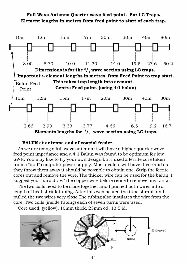
8.00 8.70 10.0 11.30 14.0 19.5 27.6 50.2Dimensions is for the 3/4 wave section using LC traps.
Important :- element lengths in metres. from Feed Point to trap start.This takes trap length into account. Centre Feed point. (using 4:1 balun)
2.66 2.90 3.33 3.77 4.66 6.5 9.2 16.7Elements lengths for 1/4 wave section using LC traps.
10m 12m 15m 17m 20m 30m 40m 80m
10m 12m 15m 17m 20m 30m 40m 80m
Full Wave Antenna Quarter wave feed point. For LC Traps.Element lengths in metres from feed point to start of each trap.
BALUN at antenna end of coaxial feeder.As we are using a full wave antenna it will have a higher quarter wave
feed point impedance and a 4:1 Balun was found to be optimum for lowSWR. You may like to try your own design but I used a ferrite core takenfrom a "dud" computer power supply. Most dealers will have these and asthey throw them away it should be possible to obtain one. Strip the ferritecores out and remove the wire. The thicker wire can be used for the balun. Isuggest you "hard draw" the copper wire before reuse to remove any kinks.
The two coils need to be close together and I pushed both wires into alength of heat shrink tubing. After this was heated the tube shrank andpulled the two wires very close The tubing also insulates the wire from thecore. Two coils (inside tubing) each of seven turns were used.
Core used, (yellow), 10mm thick, 23mm od, 13.5 id.
Balanced
Unbal
a
b
a
b
Balun FeedPoint
41

It is interesting to compare the computer predictions with the actualresult obtained in practice. My antenna is at an average height of 10metres. The table below shows the resonant frequencies and the bandwidthfor an SWR of up to 2:1.
Band FreqMhz
2:1 B/WKHz
FreqMHz
SWR less than2:1 B/WKHz*
80 m 3.61 94 3.65 1.05 300
40 M 7.1 106 7.1 1.5 200
30 m 10.142 123 10.125 1.3 50
20 m 14.129 188 14.0 1.0 350
17 m 18.1 197 18.07 1.5 100
15 m 21.2 260 21.2 1.1 450
12 m 24.94 377 24.9 1.1 100
10 m 28.5 433 29.0 1.2 1700
Computer Actual
Computer showed that with a matched source the SWR was 1:1 atresonance. The actual SWR is shown for the resonant frequency. All theseare without an ATU. The bandwidth in practice is wider than the computerprediction. I don't know why this is but suspect it's due to the type of trapsused, it was a welcome bonus ! (* band limits prevent a full assessment).
For Transistor rigs an ATU is recommended to keep within the rigs SWRlimits across the bands..
Coax feeder, 4:1 Balun and SWR.It is important that you know if your SWR reading is correct. Many SWR
meters are inaccurate. I have three different SWR bridges and all givedifferent readings ! Only one is accurate enough to obtain true SWRreadings. I use The Howes SWB30 for accurate reading but also have aKenwood AT230 and one of unknown make. They all give indications ofSWR and can be used to adjust for a low SWR. However SWR can be greatlyeffected by the coax used and this should be checked before relying onSWR measurements.
The way to do this is first connect a 50 ohm dummy load directly to theoutput of the SWR bridge. If the bridge is accurate it should show a 1:1SWR. Next connect the coax you are going to use in place of the dummyload and transfer the 50 ohm load to the far end of the coax. The SWRshould still be 1:1 if the coax is OK and 50 ohm.
I did this at 3.7MHz and 28.5 MHz and obtained 1:1.
42

I then connected the 4:1 Balun described to the far end of the coax andconnected a 200 ohm dummy load to the output (antenna) side of thebalun. The SWR was still 1:1 on all bands except 3.7 MHz where is was 1.2.This was considered reasonable but indicated that the ferrite (which aidscoupling at low frequencies) could do with improvement at a later date.
These tests showed that the feeder system was satisfactory and that SWRreading with the antenna connected would be reliable.
Another useful check is to add an additional length of the same coax intothe feed line. If all is OK the SWR readings should stay the same. If the SWRvary it may be do to standing wave on the feeder due to an unbalancedsystem. This check should be carried out on each band.
These are all simple checks but help to ensure you are getting optimumresults from your antenna system. A well balanced antenna system will notonly help avoid TVI, BCI and breakthrough on neighbours telephones butalso greatly reduce noise and interference which would otherwise be pickedup on the vertical section of the coaxial feeder. When conducting these testsalways use the minimum amount of power that will give a full scalecalibration with the SWR bridge in its most sensitive setting. Also checkthat the frequency in not in use before conducting tests with the antennaconnected. You should also give you call sign during any tests to complywith licence conditions.
Bargain buy.I had managed to buy (for £5) a 300 metre reel of unknown coax at a car
boot sale. It had an aluminium braid and sheath, solid dielectric andcopper inner wire. I was told by several amateurs (in the know !) that it wasnot suitable for amateur radio. Conducting the tests described it proved tobe 50 ohm very low loss and give a 1:1 SWR at all test frequencies, and, itwas also less weight than normal coax.
Connecting to the braid posed a problem because it was impossible tosolder, but I solved this be fitting a double screw brass connector to thebraid and then soldering the brass connector to the balun. The finishedspreader with balun and coax in place was coated with a generous amountof Yacht varnish.
SWRThe standing wave ratio along the feeder is dependant entirely on the load
presented at the antenna end, and no amount of alteration at the transmitterend can alter the actual SWR.
Take an example of where the SWR is 2:1 due to a mismatched antenna.The SWR meter at the transmitter will show 2:1 (assuming no loses in the
feeder system). Using an ATU to reduce this to 1:1 at the transmitter willnot change the actual SWR and a second SWR meter placed in circuitbetween the ATU and feeder will still show that it is 2:1. However matchingthe transmitter in this way will ensure that (with a transistor rig) the P.A. is
43

protected and also delivering its full power output to the antenna system.However a 2:1 SWR means that some of the transmitted power arriving
at the antenna end of the feeder is being reflected back down to thetransmitter end. As this is mismatched some of that it reflected back up tothe antenna. This goes back and forth until it is dissipated in the feederline. This loss is why a "lossy" coax will show less SWR than a low losscable. In other words, if you improve the quality of the coax used you maywell find the SWR has increased !
What is the effect of this high SWR in practice? In an effort to find out I set up a remote RF indicator to measure the
radiation from the antenna. Starting at the resonant frequency of theantenna on 80 m the SWR was 1.05:1 without an ATU. I set the RFindicator to read full scale.
Changing frequency to get an SWR of 2:1 the RF indicator showed only avery small reduction in radiation. I then used an ATU ( AT230) to adjust theSWR to 1:1, the indicated radiation dropped slightly more ! Most likely dueto losses in the ATU. Checking at both band edges showed the sameresults. Only when the SWR was higher than 3:1 did the ATU show animprovement in the radiated signal.
SWR up to 3:1 seems to have little effect on the radiated signal. In fact theintroduction of the ATU showed a loss of about 0.5dB in radiated power !
However it is important to keep SWR low with transistor P.A. stages toprotect the P.A. transistors and also ensure maximum power output, assome transistor transmitters automatically reduce power output if the SWRis high. It is also good practice in any case to aim for a low SWR with anyantenna system.
These findings should not be taken as conclusive but were unexpectedand seem to indicate that we may worry far to much about high SWR .
Balun.There was a very considerable reduction in received local noise. I believe
this is due to having a balanced system and using a balun, greatly reducingnoise picked up on the coax down lead. On 80 metres the reduction wasaround 5 'S' points.
Results in practice.On transmit reports were good on all bands even though conditions were
very poor. It will take a longer period to fully check the performance, butfirst signs are very encouraging.
It's a real joy to be able to switch bands without having to tune an ATU !
44

Computer prediction ofAntenna Polar Plots28.5 MHz to 3.7 MHz
at a height of 20 metres.
28.5 Mhz 24.94 Mhz
18.1 Mhz21.225 Mhz
14.2 Mhz 7.1 Mhz
3.7 Mhz
The extra lobes at some frequencies are due to the currentdistribution in the unused elements due to the harmonic relation-ship between various amateur bands. This has not proved a problemin practice (see current distribution plots). The plots shown are at thefirst major elevation lobe (small diagram on right hand side of eachplot).
The antenna height will change these elevation angles of radiation.
45

Computer prediction of the current distribution. These are typical of what happens due to the harmonic relationship of
amateur bands. The smaller currents flowing in the other sections causesminor extra lobes to appear in the radiation patterns.
Note 3.7 MHz uses whole antenna so no extra current points.
28.4 MHz
14.2 MHz
7.1 MHz
3.7 MHz
46

Alternative Versions of the Multi-band Antenna.Depending on the amount of space available, you may like to try one of
these.1.5 wavelength centre fed, overall length 101 metres
For this use the 3/4 wave element lengths on both sides and a 4:1 Balun.Half wave centre fed, overall length 33 metres.
For this use the 1/4 wave element lengths on both side a 1:1 Balun (not4:1) may be better in some installations. This version may work without aBalun but this is not recommended.
Radiation.The 1.5 wavelength will have similar radiation to the fullwave version but
with some extra lobes.The half wave version will be similar to a normal dipole, but with some
extra lobes.Height
The height used for the antenna will have considerable effect on theelevation angle radiation. The effect of this can be seen in the Polar diagramplots shown. On 80 metres it will be very high angle unless you happen tohave a 80 metre tower !
Element Lengths.Also nearby trees, buildings and diameter of wire used can effect the
element lengths required. Be prepared to make minor adjustmentsalthough the wide antenna bandwidth found in practice will cover mostsituation. If required the use of an ATU will enable a 1:1 match to beobtained at all frequencies 80m to 10m.
FinallyDid I meet my goals?1. Must cover at least five HF bands. - Covers Eight.2. Low SWR at the design frequencies. - Yes3. Not need an ATU. - No, except for large changes in frequency.4. Have same radiation pattern on each band. - Similar.5. Be easy to repeat the construction. - Repeatable6. Be adaptable for different locations. - Yes
Did I meet my goals ? You be the judge !
47