Embed Size (px)
Citation preview

THE FUTURE OF THE TECHNOLOGIES OF SHELL AND SPATIAL STRUCTURES. BRIDGES
A. Samartin
Professor of Structural Mechanics. ETSI Caminos. Technical University of Madrid Ciudad Universitaria 28040 MADRID e-mail: [email protected]
1. INTRODUCTION
The bridge represents a particular spatial structure with its own personality, function and design characteristics that has generated a very extensive and specialized literature. The bridge aims to solve the conflict produced by the intersection of two or more traffic flows. In other occasions the bridge has to surpass an obstacle either natural (river, valley) or man made one (building). Then it is natural that the birth of the bridge has to be found with the communication needs of the first man [ 1]. Although the bridge corresponds to a very common and extensively used construction, very close to the day by day living, its span very often produces surprise and admiration as it can be noticed by the many bridges existing everywhere with the name "Bridge of the Devil".
The objective of this lecture is try to predict the future of this important type of spatial structures. In this way the activities of the different lASS Technical Working Groups can be stimulated and coordinated in order to play a more relevant role in this future. To grasp a possible evolution of bridges it is convenient a reflection on the bridge history and on their present situation, particularly in relation to the different existing achievements.
In bridge development many interrelated factors have intervened, among which the following ones can be mentioned: (1) Use of new materials. (2) New structural types and methods of analysis. (3) Development of innovative construction techniques (4) Demand for new bridge uses
More recently the worldwide conscience of the limitations of the earth resources and the habitat impact of man's construction have been factors that have influenced the present bridge evolution. In this respect in current bridge designs considerations about milieu, aesthetics, amount of resources demanded and maintenance facilities together with other aspects related to the structural efficiency, construction performance and overall economy can be observed. Currently, in post- industrial countries their transportation systems are nearly completed and therefore the demand for construction of new bridges is diminished, although new mass transport systems, as the TGV in Europe,
open some limited perspectives. This fact introduces a new component in a bridge design, namely the bridge management. In this term, the inspection, detection, tests and eventual replacements of the bridges, i.e. a new and important task for the bridges builders or "pontifices" is included.
This lecture will be divided as follows. First the mechanisms for bridge developments will be discussed. Then the different components, with influence on the bridge design -material, structural type and analysis, construction and management of the bridges- will be subsequently commented on. Finally some illustrative and representative examples of current bridge projects will be shown. Obviously it is not possible, in the framework of this lecture, to be complete in this presentation, due to time and space limitations. Thus, personal taste and the availability of the material presented have played a very decisive role. The paper will be finished with some reflections about the future trends in the bridge technology and how this future can influence on the current technical activities of the different lASS Working Groups.
2. MECHANISMS OF BRIDGE DEVELOPMENT.
The essence of the bridge is to span over an obstacle. This fact represents mainly a technical problem, that means that for a given state of available materials, known structural types, methods of analysis and construction, the design of an specific bridge of a fixed span, soil conditions and traffic demands lies between narrow possibilities assuming a given economic context.
A development in the bridge technology appears when a new solution is introduced in the project. Obviously that occurs in the limit situations, in the very large spans. In the present, the challenges of the Gibraltar and Messina bridges, new problems appear and the design of these bridges is quite far from the one commented by Sejoume in reference to the stone arch bridges " ... the design of a bridge is only question of experience, it is sufficient to observe the past built ones".
In the range of large spans, cable stayed bridges and suspension bridges are dramatically competing one against other for the first place, although for the very large spans the type of the Golden Gate bridge in San Francisco still remains its leadership. However there are bridges like the Bay bridge from Oakland to San Francisco containing both structural types by changing its suspension bridge type into the cable stayed one at the intermediate island Yerba Buena. The Golden Gate is a beautiful bridge (Fig.l) and still remains a symbol of the suspension bridges although its impressive span at that time, 1,280 m, has been surpassed during the last decades. This is a consequence of the continuous advances in the bridge technology as has been reported in a recent survey [2] and can be also observed in table 1.
The longest suspension bridge under construction had been originally designed to carry highway and rail road traffic with a span of 1, 7 68 m but in 1985 a decision was made to change it to only highway traffic with an increase in the span to 1,990 m. i.e. more than the 1.5 times the Golden Gate span. It is a three-span, two stiffening girder system

suspension bridge. The total length of the bridge is 3,910 m with 1,990 m as central span. The width deck is 35.0 m. The bridge has been designed by Honshu- Shikoku Bridge Authority (Japan) for a water current speed of 4.5 m/s, wind speed of 80 m/sand an earthquake of magnitude Richter of 8.5. The estimated cost in 1985 dollars was 2,3 billion. A view of this impressive bridge is shown (Fig. 2).
Figure 1. Golden Gate Bridge Figure 2. Akashi Kaykyo Bridge
Name Centre sgan Country Year Completed 1 Akashi Kaikyo Bridge 1,990 Japan 1998 (est) 2 Great Belt East Bridge 1,624 Denmark 1998 (est) 3 Humber Bridge 1,410 England 1981 4 Jiangrin Br. over Yangtze 1,385 China 1997 (est) 5 Tsing Ma Bridge 1,377 Hong Kong 1997 (est) 6 Verrazano Narrows Bridge 1,298 USA 1964 7 Golden Gate Bridge 1,280 USA 1937 8 Hogsten Bridge 1,210 Sweden 1998 (est) 9 Mackinac Straits Bridge 1,158 USA 1957 10 Minami Bisan-seto Bridge 1,100 Japan 1988
TABLE 1.- Suspension bridges
With the construction of the AK Bridge the proposals made by T.Y. Lin of 5,000 m of span bridge for crossing the Gibraltar Strait and by Freeman Fox to have a span of 3,200 m for the Messina crossing are became more realistic ones.
The competition to the suspension bridges are coming in the shorter spans from the cable stayed bridges. They were first introduced in Germany by Leonhardt and others to reconstruct the destroyed structures occurring during the second word war. Economic and aesthetic reasons explain their spread throughout Europe and other parts of the world. In the range of 200- 600 m, it is the predominant structure but increasing span possibilities are still open. In table 2 some large span cables stayed bridges are reported. It is important to distinguish in these bridges the deck material, steel or concrete. However it can be observed that the largest span bridges, the N ormandie Bridge projected by Virgoleux and his team of the Bridges Division of SETRA in Paris, correspond to composite decks. The main span consists of 620 m of steel orthotropic box
segments and the rest of the bridge deck is made up of concrete box segments.
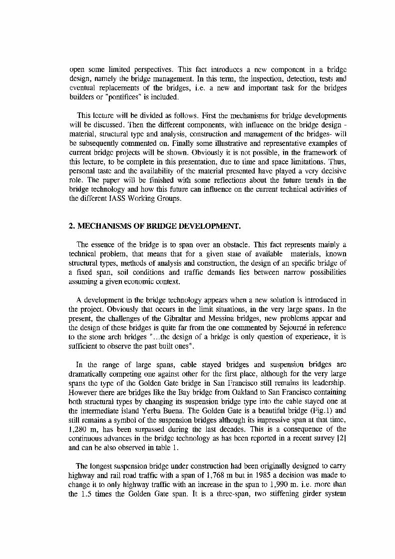
Figure 3. Barrios de Luna Bridge
Name Centre span 1 Normandie 856 2 Tsurumi Tsubasa 510 3 Barrios de Luna 440 4 Annancis Bridge 465 5 Dame Point 396 6 Luling 373
TABLE 2.- Cable stayed bridges.
The Barrios de Luna Bridge has been designed by the Carlos Femandez Casado OT. It is located in the northern of Spain and it crosses a deep reservoir near the city of Leon. The shortest crossing of the reservoir required the impressive span of 440 m and two side spans of 66.7 4 m, and this structure therefore, holds the record for the longest concrete cable stayed span. In the centre portion of the bridge, where axial forces produced by the stays are small, part of the lower flange of the box section was eliminated. The two H-shaped towers have a height over the deck level of 90 m. The deck is monolithic with the counterweight and has a sliding hinge joint at the centre of the main span. The disadvantages of this centre hinge are the discontinuity of the riding surface and the need for the joint to transmit and resist shear and torsional forces. By the contrary, bending moments are reduced along the centre zone of the bridge centre (Fig 3).
Deck Country Year completed Composite France 1995
Steel Japan 1994 Concrete Spain 1983
Steel Canada 1986 Concrete USA 1988
Steel USA 1983
One of the largest cable stayed bridges in the world is the Tsurumi Tsubasa Bridge in Japan. This 1020 m long bridge with a central span of 510 m, single-plan, three-span continuous cable-stayed bridge was constructed over Tsurumi Fairway, which lies between the Daikoku-Futo and Ogishima Island in Yokohama, by Metropolitan Expressway Public Corporation of Japan. The inverted Y shaped towers are 163 m over the deck level. The cable arrangement is the semi-fan type. The single plane disposition for the cables is due to the plan to built a twin parallel bridge to the existing one and avoid unpleasant visual effects. The steel five cells box section is 38,00 m width and 4,00 m hei!!ht.
""
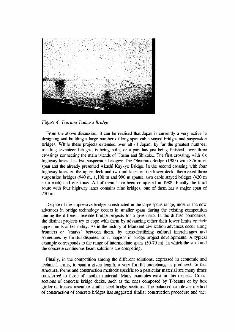
Figure 4. Tsurumi Tsubasa Bridge
From the above discussion, it can be realised that Japan is currently a very active in designing and building a large number of long span cable stayed bridges and suspension bridges. While these projects extended over all of Japan, by far the greatest number, totalling seventeen bridges, is being built, or a part has just being finished, over three crossings connecting the main islands of Hoshu and Shikoku. The first crossing, with six highway lanes, has two suspension bridges: The Ohnaruto Bridge (1985) with 876 m of span and the already presented Akashi Kaykyo Bridge. In the second crossing with four highway lanes on the upper deck and two rail lanes on the lower deck, there exist three suspension bridges (940 m, 1,100 m and 990 m spans), two cable stayed bridges (420 m span each) and one truss. All of them have been completed in 1988. Finally the third route with four highway lanes contains nine bridges, one of them has a major span of 770m.
Despite of the impressive bridges constructed in the large spans range, most of the new advances in bridge technology occurs in smaller spans during the existing competition among the different feasible bridge projects for a given site. In the diffuse boundaries, the distinct projects try to cope with them by advancing either their lower limits or their upper limits of feasibility. As in the history of Mankind civilization advances occur along frontiers or "marks" between them, by cross-fertilizing cultural interchanges and sometimes by fruitful disputes, so it happens in bridge project developments. A typical example corresponds to the range of intermediate spans (50-70 m), in which the steel and the concrete continuous beam solutions are competing.
Finally, in the competition among the different solutions, expressed in economic and technical terms, to span a given length, a very fruitful interchange is produced. In fact structural forms and construction methods specific to a particular material are many times transferred to those of another material. Many examples exist in this respect. Crosssections of concrete bridge decks, such as the ones composed by T -beams or by box girder or trusses resemble similar steel bridge sections. The balanced cantilever method of construction of concrete bridges has suggested similar construction procedure and vice
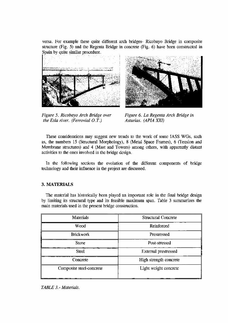
versa. For example these quite different arch bridges- Ricobayo Bridge in composite structure (Fig. 5) and the Regenta Bridge in concrete (Fig. 6) have been constructed in Spain by quite similar procedure.
Figure 5. Ricobayo Arch Bridge over the Esla river. (Ferrovial O.T.)
Figure 6. La Regenta Arch Bridge in Asturias. (APIA XXI)
These considerations may suggest new trends to the work of some lASS WGs, such as, the numbers 15 (Structural Morphology), 8 (Metal Space Frames), 6 (Tension and Membrane structures) and 4 (Mast and Towers) among others, with apparently distant activities to the ones involved in the bridge design.
In the following sections the evolution of the different components of bridge technology and their influence in the project are discussed.
3. MATERIALS
The material has historically been played an important role in the final bridge design by limiting its structural type and its feasible maximum span. Table 3 summarizes the main materials used in the present bridge construction.
Materials Structural Concrete
Wood Reinforced
Brickwork Prestressed
Stone Post -stressed
Steel External prestressed
Concrete High strength concrete
Composite steel-concrete Light weight concrete
TABLE 3.- Materials.
Leaving aside historical materials like stone, brickwork and wood, the two main ones currently used, steel and concrete, together with their combination in the new structural "material" known as composite materials, will be shortly discussed in the following.
(a) Concrete.
The limitation of concrete, represented by the low ratio strength/self weight in comparison with the higher similar ratio of the steel is well known. However in the latter material, its initial cost and the required maintenance against corrosion are the mam disadvantages of its use in range of short spans.
There exist several alternatives within the concrete material and some of them are listed in the second column of table 3. For small spans reinforced concrete decks seem to be sufficient to carry out the gravity loads but they should be changed into prestressedpre or post tensioned- concrete decks as the spans increase. Usually these solutions are linked to prefabrication, but also many cast-in-place bridges are built. In the range of medium spans, the number of applications of prestressed concrete is very large and the current trend is towards to an increase, achieved by introducing high strength and lightweight concrete in order to ameliorate the ratio strength/ self weight of this material. The possibilities introduced by external prestress in the design of new bridges and in the repairing of existing ones are at present dramatically increased. Versatility and replacement facilities are some of the many advantages offered by external prestress, however some disadvantages such as inefficiencies to resist the ultimate load, stress concentration or difficulties in the model of its structural performance still demands further study and special attention.
The future of the concrete bridges can be grasped by observing the existing records in the different bridges types. The summary presented in [3] is given in the following:
(1) Cable stayed bridges. The already mentioned bridge of Barrios de Luna (1983) with its 440 m represents the maximum span. (2) Arch bridges. The potential of this structural type is shown by the 390 m span of San Marcos-KRK (1981) in the Adriatic Sea. (3) Frame bridges. The central span of the 250 m of the prestress bridge with vertical supports for the Oporto Underground has been surpassed in the complete design by a similar bridge with 310 m at nearly the same location. (4) Beam bridges. The current record is represented by the 260 m of main span of the Gateway bridge in Australia.
Summarizing concrete is in comparison to steel very adaptative to any form and aesthetically pleasant material. Its main advantages usually became more in the medium spans range. To improve its structural performance, several possibilities are currently under consideration: (1) Use of high strength or light weight concretes or different concrete materials in the same structure, (2) New structural schemes, (3) Composite materials and ( 4) Substitution of the reinforced steel by special fibres like kevler and arapree.
(b) Steel
The efficiency of steel has been shown since its use as structural material in the railways bridge of Firth of Forth (1890) in Scotland and in 1931 the George Washington in New York, spanning more than one kilometre of span over the Hudson river (1,031 m). The largest spans for each structural type belong to this material as can be noticed in the following summary of the current records.
(1) Cable suspension bridges. The Humber Bridge in UK is the largest (1,410 m) already built steel suspension bridge as it has earlier been noted. (2) Cable stayed bridges. The Annacis bridge with 467 m is also a record in this class but exists a project of a similar type with 780 m. near El Havre (France). (3) Arch bridges. The record is represented by the New-River Gorge in West Virginia USA (1980) with the largest span (510 m). (4) Frame bridges. The record is hold by the viaduct of Sfalassa in Italy (1980) for the autostrada Salerno-Reggio with the span of 376 m subdivided by the inclined struts into 108-160-108 m. (5) Beam bridge. The present largest steel beam bridge, (no trusses are included in the group), is still the well known Niteroi Bridge (1975) with its 300 m span.
It can be concluded that steel will maintain its leadership among the other materials in the very long span bridges due to its high structural efficiency. Steel bridges are also very economic, competitive and suitable in the range of long and medium spans. It can be observed that practically every structural type of bridge has a steel representative with a long span. However the high cost of steel and its maintenance restricts its use in the range of small and very small spans.
(c) Composite materials
The composite materials, i.e. the simultaneous best use in the bridge structure of both materials- concrete and steel- has become an extremely competitive solution due to the need to reduce the cost and the time required for execution. There are two groups of composite bridges: Longitudinally and transversally composite bridges.
It has been already mentioned the recent Normandy bridge that represents an outstanding example of the first group. A part of its 856 m of span is made in steel and the another in concrete. This longitudinally composite solution may be interesting for long spans or in very specific cases where dead weight reduction is mandatory, like large differences between adjacent spans. Others cases of increasing application of this group of composite materials correspond, as the one in the example, to cable stayed composite bridges.
In the transversal composite bridge both structural materials interact one with each other at each cross section of the deck. It corresponds to a frequently adopted solution in the current practice. A recent survey of the situation of these bridges can be seen [ 4] . Most of the transversal composite bridges adopted in the present time belongs to one of
the two types:
(1) Composite decks with two plates girders. They are used extensively in Europe for highway and railway bridges, as TGV in France. The trend of the plate girders is to increase the thickness of the flange plates, reaching 150 mm or more with in situ quality control in welded joints due to the advances existing in the welding technology. An alternative to reduce these large thicknesses is widening the flange, but if large widths are needed (about 1,000 mm) the following solution type may be better.
(2) Single cell composite box girder decks. Usually this solution is more expensive, but it can be advantageous in long span, curved bridges decks and in cases where a high slenderness is adopted for aesthetic considerations as in urban bridges. The possibility in this solution of using a single bridge pier, even in decks several boxes in comparison with the need of introducing a pier cap or several piers to support the different beams of the solution (1) represents an important structural and aesthetic advantage. However it should be taken into consideration when comparing both solutions that, apart from the increased execution time required for box girders, transport is more expensive and difficult due to the limitations produced by road restrictions for the dimensions of the structural parts to be transported.
Among the recent developments carried out, particularly in France, on transversal composite bridge decks the following ones may be cited:
( 1) Trapezoidal box girders with two concrete flanges and webs made of steel stiffened plate or steel trusses.
(2) Triangular box girder where the lower flange is reduced to a steel tube (eventually filled with concrete) and two corrugated steel webs.
(3) Spatial steel truss with a concrete deck slab. An outstanding example of this group on the best use of the modem bridge technology corresponds to the experimental viaduct (Roise bridge) designed by Jean Muller, in which the high strength concrete of the slab in conjunction with an external prestress permits a reduction of the slab thickness to 140 mm.
4. STRUCTURAL FORMS
In a bridge project, every possible structural type can be considered. Some of them, as the column and the wall, are specific of parts of the bridges- piers and abutments. If the bridge superstructure is focused and along the path of the compressive stresses, the arch represents the major load supporting invention of the classic art and a very impressive structure as well. As Torroja wrote [5]: "Si la columna es arquitectura pura, el arco es ingenieria; ... " both have in common the fact of the same resistance pattern by compressive stresses.
When stone was the available material for the bridge engineer, the arch was
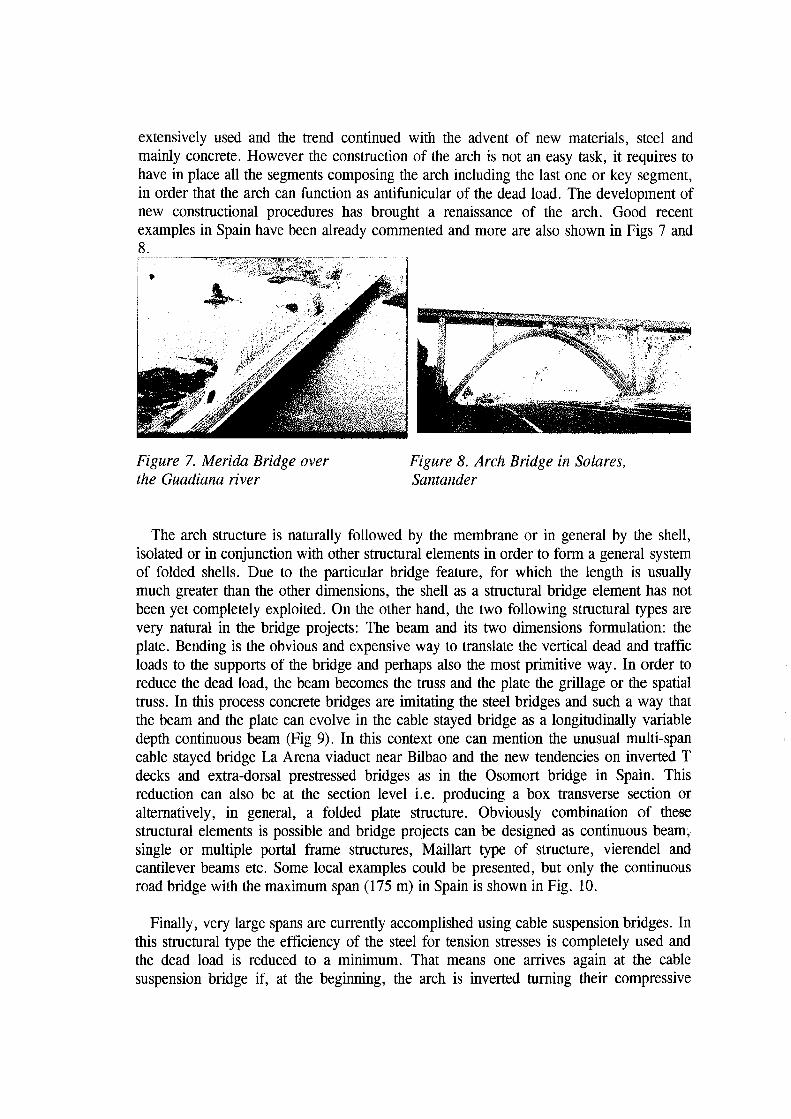
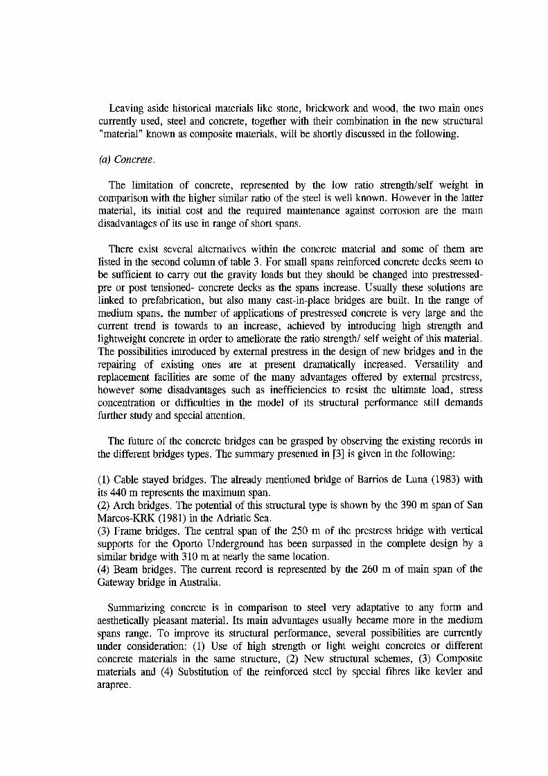
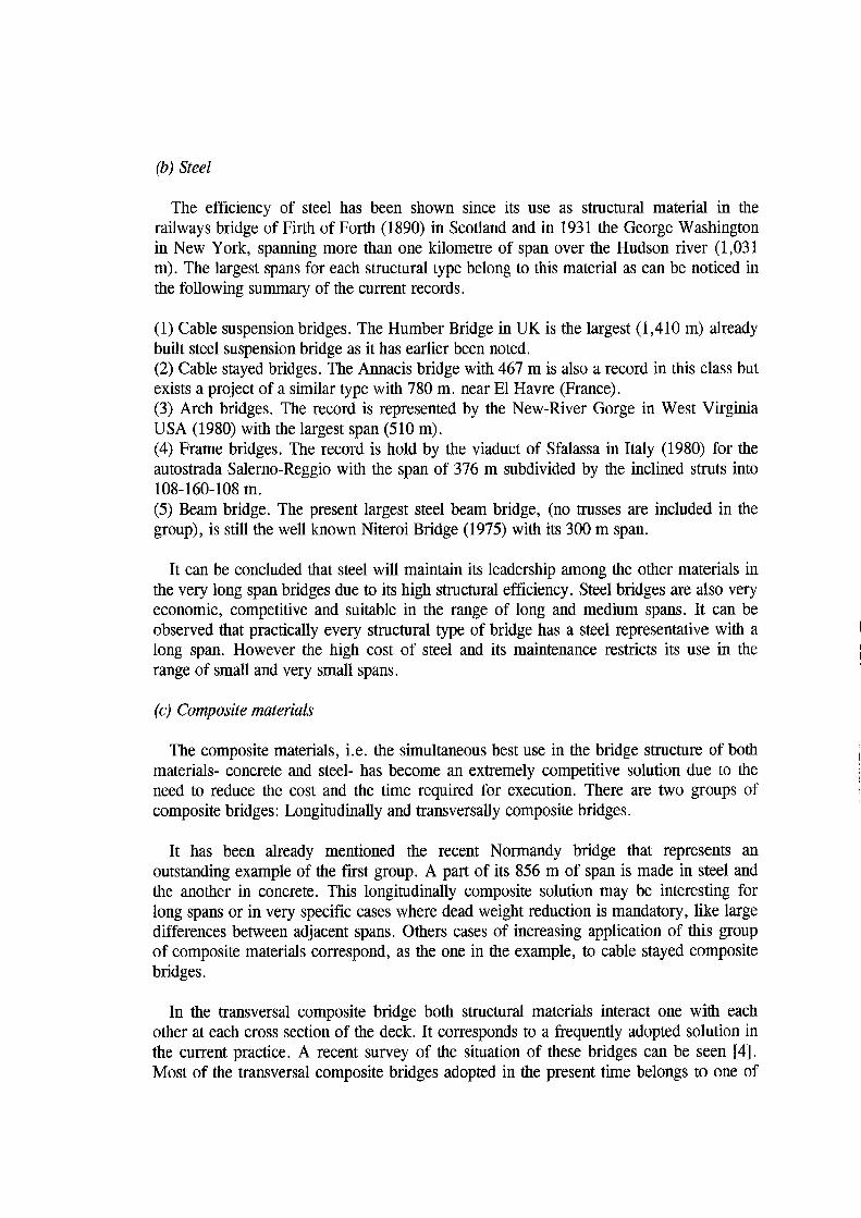
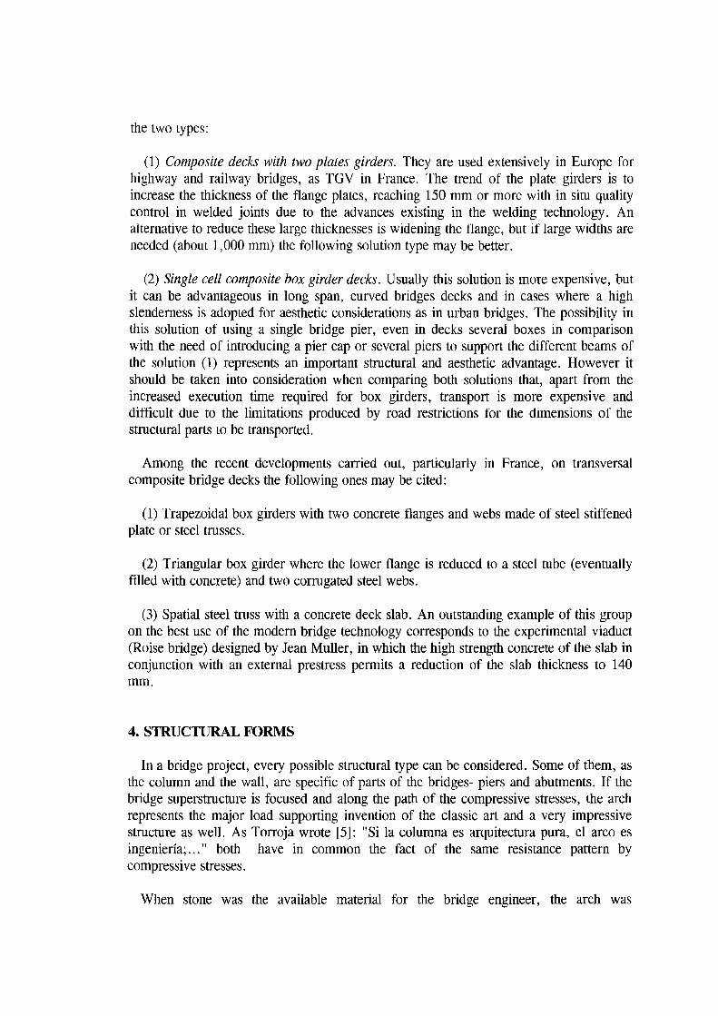
extensively used and the trend continued with the advent of new materials, steel and mainly concrete. However the construction of the arch is not an easy task, it requires to have in place all the segments composing the arch including the last one or key segment, in order that the arch can function as antifunicular of the dead load. The development of new constructional procedures has brought a renaissance of the arch. Good recent examples in Spain have been already commented and more are also shown in Figs 7 and 8.
"
Figure 7. Merida Bridge over the Guadiana river
Figure 8. Arch Bridge in Solares, Santander
The arch structure is naturally followed by the membrane or in general by the shell, isolated or in conjunction with other structural elements in order to form a general system of folded shells. Due to the particular bridge feature, for which the length is usually much greater than the other dimensions, the shell as a structural bridge element has not been yet completely exploited. On the other hand, the two following structural types are very natural in the bridge projects: The beam and its two dimensions formulation: the plate. Bending is the obvious and expensive way to translate the vertical dead and traffic loads to the supports of the bridge and perhaps also the most primitive way. In order to reduce the dead load, the beam becomes the truss and the plate the grillage or the spatial truss. In this process concrete bridges are imitating the steel bridges and such a way that the beam and the plate can evolve in the cable stayed bridge as a longitudinally variable depth continuous beam (Fig 9). In this context one can mention the unusual multi-span cable stayed bridge La Arena viaduct near Bilbao and the new tendencies on inverted T decks and extra-dorsal prestressed bridges as in the Osomort bridge in Spain. This reduction can also be at the section level i.e. producing a box transverse section or alternatively, in general, a folded plate structure. Obviously combination of the-se structural elements is possible and bridge projects can be designed as continuous beam; single or multiple portal frame structures, Maillart type of structure, vierendel and cantilever beams etc. Some local examples could be presented, but only the continuous road bridge with the maximum span (175 m) in Spain is shown in Fig. 10.
Finally, very large spans are currently accomplished using cable suspension bridges. In this structural type the efficiency of the steel for tension stresses is completely used and the dead load is reduced to a minimum. That means one arrives again at the cable suspension bridge if, at the beginning, the arch is inverted turning their compressive

internal forces into tension ones and the concrete into the steel.
Figure 9. Badajoz Bridge over the Guadiana river
Figure 10. Viaduct over the Tag us river in Almaraz.
Summarizing, every structural type can be and has been used in a bridge design. However the maximum span is a key variable among others in the selection of the most economic structural type for a given project. Despite this fact, in many cases there exist fuzzy boundaries between the most suitable structures for a given bridge project. For example very shallow arches and longitudinally variable depth beams can be confused in many prestressed concrete bridges constructed some decades ago. In the future longitudinal and transversal reductions are envisaged as it has been indicated in this section and the interrelated section on the bridges materials.
S. ANALYSIS
The two faces of the analysis- the experimental and the numerical ones- have been dramatically developed during the last decades. The Computer revolution, the Finite Element Method and related mechanical computation techniques, the use of sophisticated electronic devices to control input and measure outputs, the advances in the Materials Sciences and in the theory of Continuum Mechanics are some examples. Due to its availability, economy and prompt output numerical analyses are usually preferred to experimental ones. However there exist situations, as in innovative or with large dimension structures for which experimental analysis together with the numerical computation is advisable. In such cases model tests can discover some unexpected structural behaviour that can not be detected by the numerical analysis, because the numerical analysis only answer the questions proposed by itself. A wind tunnel test could prevent some suspension bridges failures. Besides model tests permit us to consider other aspects than structural stability, like aesthetics, construction procedures and functionality. In any case loading tests in the finished bridge should be compulsory.
In a report on the state of the art of numerical methods [ 6] it has been concluded that numerical models can practically simulate any structural behaviour in the linear and nonlinear range. However, the difficulties are mainly concerning with the data related to the material properties (behavioral models, elastic and plastic coefficient, creep, etc.)
and loading definitions. That means, bridge analysis, as any structural analysis will be expanded in the direction of the branches of Identification methods, Reliability theory, Optimization and as a consequence towards developments of Bridge Expert Systems.
In the bridge design, the analysis should be carried out through the different stages of the bridge life- construction and service and ultimate load. That means, in general, it must study an evolutive structure and therefore the stresses at a given time are very much dependent on the actual history of the random actions supported by the bridge during the time prior to the instant of study. An alternative to the difficult task of obtaining an accurate simulation of the behaviour of the bridge is to check its behaviour by means of a set of specified rules called a format and given in the Codes. The aim of these rules is to assess a similar safety level of the different bridges during their life stages and according to their importance and other social considerations, but these rules do not try to accurately simulate the bridges actual behaviour. The main issue in this approach is to obtain reasonable formats to assess similar levels of structural safety without an extensive analytical research and experimentation. The safety coefficients included in the current formats presently used have a long history and a large statistic background in the sense that structures designed accordingly are reasonably safe, but they do not give any quantitative indication about the safety level reached.
In the future the trend on structural simulation will be directed towards Code unification- already some tentative FIP-CEB are under way- and to set up more reliable and scientific based formats of structural safety. The developments of Code concomitant expert systems are also envisaged. That implies the use of optimization techniques, friendly pre- and efficient postprocessors able to produce output to be used directly in the different bridge project documents as part of the foreseen knowledgment based systems.
6. CONSTRUCTION
Bridge construction demands expensive work outside of the factory. For a long time, efforts have been made in order to translate this work to the fabric, i.e. towards prefabrication. In the future, bridge prefabrication will increase its share in the whole bridge construction. This trend starts with bridge deck of precast double T -beams and cast in situ decks. Later, the decks became multicellular and were completely precast. Other parts of the bridges, such as, piers, abutments and earth retaining walls have also been prefabricated. From initial simply supported bridges now continuous beams with longitudinally variable cross-section and spans up to 80 m are currently constructed in Spain. Even the deck of a cable stayed bridge has been constructed in the factory. The reference [7] corresponds to a recent state-of-art report on the prefabrication in this country.
Regarding the construction in situ, the tendency will be towards the improvement and automatization of the existing construction procedures. The computer will be an ordinary tool for the contractor on the site. Three main groups of methods of erection for bridges can be considered: the staging method, the push-out method and the cantilever method.

First in the deck construction span by span, several tendencies are under way. A common one is to fabricate the transverse crosssection in several phases. Normally a nucleus is fabricated and then, once it is put in place and used as structural support, join to the nucleus the lateral cantilevers. Sometimes the deck is divided in segments that are collocated according to different procedures, provisional piers, cranes etc. (Fig 11).
Figure 11. Viaduct over the Arnoya river in Galicia
The push-out technique has been used successfully in many occasions and has become a standard construction method, particularly in Europe. As it is well known, in this method large sections of the bridge deck are pushed out over the piers on rollers or sliding teflon bearings. The bridge is fabricated or assembled in an erection bay at one or both ends of the structure. The deck can be pushed from one abutment all the way or from the abutments towards the centre. In the Amoya viaduct near 1,000 meter of a continuous bridge, curved in plan and in elevation, is now constructed by this method. Some variations of this method consist in producing a lateral translation of the bridge or in rotating it around a provisional hinged. In particular the rotation permits building the bridge independently on the traffic or the river. An example of this method is the single pier cable stay bridge Ben-Ahin of 168 m span that has been built in Belgium.
Figure 12. Bridge over the Pontevedra Ria
7. BRIDGE FUNCTION AND AESTHETICS
The cantilever method (Fig. 12) is very often used in bridge construction, particularly when it is necessary not to interfere with the traffic below the bridge. The cantilever method corresponds to a very common bridge erection procedure and it can be observed that all the present bridge records of large and very large span bridges have been built by this method.
Throughout history the bridge has been used for other functions different to the original one. Sometimes it has served as dwelling, other occasions as a restaurant in the
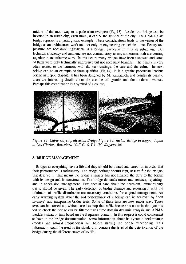
middle of the motorway or a pedestrian overpass (Fig.13). Besides the bridge can be inserted in an urban city, even more, it can be the symbol of the city. The Golden Gate bridge represents a paradigmatic example. These considerations leads to the vision of the bridge as an architectural work and not only an engineering or technical one. Beauty and pleasure are necessary ingredients in a bridge, particular if it is an urban one. But technical efficiency and aesthetic are not contradictory terms, sometimes both are coming together in an authentic work. In this lecture many bridges have been discussed and some of them were only technically impressive but not necessary beautiful. The beauty is very often related to the harmony with the surroundings, the care and the calm. The next bridge can be an example of these qualities (Fig.l4). It is a granite pedestrian Inachus bridge in Beppu (Japan). It has been designed by M. Kawaguchi and besides its beauty, there are interesting details about the use the old granite and the modem prestress. Perhaps this combination is a symbol of a country.
Figure 13. Cable-stayed pedestrian Bridge Figure 14. Iachus Bridge in Beppu, Japan atLas Glorias, Barcelona (C. F. C. 0. T.) (M. Kagawuchi)
8. BRIDGE MANAGEl\tiENT
Bridges as everything have a life and they should be treated and cared for in order that their performance is satisfactory. The bridge heritage should kept, at least for the bridges that deserve it. That means the bridge engineer has not finished the duty to the bridge with its design and its construction. The bridge demands more: maintenance, repairing and in conclusion management. First special care about the occasional extraordinary traffic should be given. The early detection of bridge damage and repairing it with the minimum of traffic disturbance are necessary conditions for a good management. An early warning system about the bad performance of a bridge can be achieved by "non invasive" and inexpensive bridge tests. Some of these tests are now under way. These tests can be carried out without need to stop the traffic because its noise in the dynamic test to check the bridge can be filtered using time domain dynamic analysis and ARMA models instead of tests based on the frequency domain. In this respect it could convenient to have in the bridge documentation, some information about its dynamic performance (modes and natural frequencies) just before starting the bridge functioning. This information could be used as the standard to contrast the level of the deterioration of the bridge during the different stages of its life.

9. CONCLUDING REMARKS.
Bridges represent very symbolic space structures connecting with the primary needs of the human society: Communication. Their continuous developments and advances have taken place by solving different problems: The challenge of the large spans and the inner competition among different solutions for a given bridge project. The bridge progress will be very much depending on the simultaneous development of the ingredients existing in the bridge technology, namely, materials, structural types and analysis, construction procedures and management. In the future the bridge, particularly the urban bridge will be considered no only as an engineering work but also an aesthetic expression of the human artistic soul.
In this context lASS represents a very unique Forum where Architects, Engineers, Builders, Contractors, Researchers among others professionals meet. That means lASS is a very suitable association to treat the different challenges involved in the Bridge technology. The existing WGs can deal some of them, namely the Morphology, Materials (Metal Space Structures and Tension and Membrane Structures) and Numerical Methods. However creation of new WGs, such as, ones related to the structural aesthetics, structural maintenance and repairing, construction techniques and conservation of historical buildings should be considered in order to identify and answer in a comprehensive way the problematic appearing in Bridge technology. To achieve these goals creation of WGs with objectives related to specific structures, such as bridges, is perhaps not convenient but coordination of existing and new WGs tasks seem to be completely necessary.
An enormous literature related to the different aspects of Bridge technology exists. Besides the already cited the references [8] to [14] are recommended for further reading.
10. ACKNOWLEDGMENTS
The author wish to publish express his grateful recognition for the help in documentation received in the preparation of this lecture to the following persons and institutions: A. J. Reis (1ST, Lisbon), S.Perez Fad6n (FERROVIAL), J. Manterola (Carlos Femandez Casado OT), M. JuWi (CUBIERTAS), A. Scordelis (Univ. of California at Berkeley), P.L. Gould (Washington Univ. in St. Louis, USA), J.l. Gonzalez-Esteban (FOMENTO), M. Kagaguchi (Hosei Univ. Tokyo), J.J. Arenas (APIA XXI), M. Buron (PACADAR) y L. Albajar (ALVISA).
11. REFERENCES
1. Wittfoht, H. "Triumph der Spannweiten" Beton Verlag, GmBH, Diisseldorf (1971) pp.lO. 2. Scordelis, A.C. "Cable-suspended bridges- Past, Present and Future" ASCE
Structures Congress, SF Lecture, (May 4, 1989). 3. Aparicio, A. "Los puentes del futuro". OP Num 20 (1991). pp 6-21. 4. Reis, A.J. "Recent developments in composite bridges" in Steel Structures. Eurosteel'95. A.N. Kounadis (Ed). Balkena/ Rotterdam. (1995). pp 383-389. 5. Torroja, E. "Razon y Ser de Ios tipos estructurales". Instituto Tecnico de la Construcci6n. Madrid. 2nd. Ed. (1960). pp-101 6. Samartin, A. "Numerical analysis of shells and space structures". Bulletin of the International Association for Shell and Spatial Structures. Vol 33, No 13.(n.107) December (1991). pp 181-188. 7. Lleyda, J.L. "La prefabricaci6n en obras civiles. Estado del arte en Espafia". Hormig6n y Acero. Num 198. Madrid (1995) pp 127-144. 8. Leonhardt, F. "Briicken. Asthetik und Gestaltung. Bridges. Aesthetics and Design". The Architectural Press: London (1982). 9. Walther, R. and al. "Ponts Haubanes". Presses Po1ytechniques Romandes (1985). 10. Gimsing, N .J. "Cable supported Bridges. Concept and Design". John Wiley and Sons (1983). 10. Podolny, W. and J. B. Scalzi "Construction and Design of Cable-stayed Bridges" . 2nd. edition. John Wiley and Sons (1986). 11. Zienckiewicz, O.C. and Y.K. Cheung "The finite element method for analysis of elastic isotropic and orthotropic slabs". Proc. Inst. Civ. Eng. 28 (1964) pp 471-88. 12. Samartin, A. Q. "01lculo de estructuras de puentes de hormig6n". Ed. Rueda. Madrid (1983). 13. Zienckiewicz, O.C. and R.L. Taylor "The Finite Element Method". 4th edition McGraw-Hill Book Co.Proc. London (1989). 14. Scordelis, A.C. et al. Reports no. UCB/SESM 76-6, 78-2, 79-3, 84-12, 86-7 and 86-13. Department of Civil Enginering. University of California. Berkeley, California.