Embed Size (px)
Citation preview

www.fullswinggolf.com
Maintenance manual cover.indd 1 1/10/11 3:22 PM

1
Screen Frame
Quiet Seamless Screen
Tee Frame
Computer Cabinet
SimulatorEnclosure
LCD WidescreenTouchscreen
Southwest Greens Hitting Matwith Simulated Sand and Rough
Full Swing Golf SimulatorYour Full Swing Golf simulator is a combination of cutting edge software, commercial-grade projector, precise ball tracking technology, and the time-tested durable enclosure. By getting to know your simulator, and keeping up with the little-required maintenance, you can enjoy games, movie, and sports for years to come.
maintenanceManual.indd 1 12/22/10 2:03 PM

2
The Full Swing Golf Simulator is an incredible product, the result of many years of engineering along withproduct research and development. While the simulator is put together as a turnkey unit, it is made up of many different components that create an experience of lifelike realism. Much like your automobile, the Full Swing Simulator will require regularly scheduled maintenance to keep it running optimally. By closely following this maintenance schedule the Full Swing Golf Simulator will provide many years of enjoyment.NOTE: Maintenance Checklists are provided for your convenience at the end of this manual.
1. Inspect the bungee cords around the screen for wear. Look for broken, over-stretched or loose bungees and replace as needed. Replacement bungees can be ordered directly from Full Swing Golf.2. Inspect the ceiling baffles and the flaps around the screen. If they come undone, refasten the Velcro.3. Inspect the screen for rips or tears. These can be caused by broken clubs, wooden tees, or cracked balls. If a tear is present, patch it soon or it will continue to grow to the point that it is impossible to repair.4. Inspect Tees for wear and breakage.5. Clean the clear areas on the Lexan covers with a rag lightly dampened with Windex or water. This will prevent the accumulation of dust, which reduces the sensitivity of the sensors.6. Clean the projector filter. Panasonic recommends this be cleaned every 100 hours and replaced at the same time as the lamp. Refer to your projector’s operation manual for location and instructions. To clean the filter, use a small can of compressed air available at most computer and electronic stores.7. Check the lamp hours on your projector. The lamp-life in a Panasonic projector is roughly 2000 hours (3000 in low power mode). It is recommended that you keep track of the hours used so you can order a spare lamp when you are near your limit. The lamp hours can be accessed through the on-screen menu using your remote control. Please refer to your projector’s operation manual for location and instructions. Replacement lamps can be ordered directly from Full Swing Golf.NOTE: Please see page 7 for more information on projector service.
1. Vacuum the simulator as needed, but do so at least once per month. This will reduce dust in the area and prolong the life of the electronics. Do not vacuum on, over, or near the tracking sensors. This will eventually remove the protective coating on the Lexan covers and static discharge may damage the sensors.WARNING: You must turn the master power switch to the OFF position before vacuuming. Failure to doso could result in damage to the sensors due to static electricity.2. Rotate the hitting mat 90 degrees. This will prolong the life of the mat.3. Check for tracking problems by running NOMASK, the diagnostic program for the simulator (See page 4).
MAINTENANcE
Weekly Maintenance
Monthly Maintenance
The Tracking SystemTracking System OverviewThe Infrared Tracking System in your simulator consists of two tracks or Frames. These Frames contain the electronic sensor boards that track the golf ball as it passes through them. To protect these sensor boards they are covered by highly durable Lexan Covers. The Lexan Covers are visible as you walk into
maintenanceManual.indd 2 12/22/10 2:03 PM

3
Weekly Maintenance
Monthly Maintenance
The Tracking System
the simulator near the Screen. The first frame you come to, the frame closest to the Tee Box, is referred to as the TEE Frame. The second frame, closest to the Screen, is referred to as the ScREEN Frame.
These sensor boards work together to create two Infrared Grids. These Grids cycle at an extremely fast rate and can instantly track a golf ball traveling as slow as 2 mph and faster than 200 mph. As the ball passes through the two Grids, trajectory and velocity are determined. This tells the computer how fast and at what angle the ball left the tee. However, to get an accurate flight path, the computer needs one more piece of data: ball spin. The spin of the ball is tracked after the ball hits the screen and bounces off. Depending on the spin, the ball will bounce off the screen at different angles and pass back through the SCREEN Frame.
Using these three points of reference the computer can accurately determine the path the ball will travel. As you will notice, all of this is calculated in a fraction of a second and instantly displayed on the screen. Due to these highly sensitive tracking sensors it is not necessary to tell the computer what type of club is being hit. In fact you can throw, toss, or roll a ball with the same accurate results. You have purchased a truly unique and amazing machine.
To keep your simulator in optimum condition, it is recommended you run the NOMASK diagnostic program at least once per month. It takes only a few minutes and will keep your simulator running smoothly with a minimum of downtime. NOMASK is a diagnostic tool used to identify problems or potential issues with the Tracking System. Although the system was designed to last several years without failure, sometimes, electronic equipment can be damaged by natural or environmental causes.
NOMASK is designed to quickly find and resolve issues related to the Tracking System. The system isdesigned to work even though certain parts may be damaged. This is known as a redundant system. However, if several parts are damaged, or certain critical parts are damaged, the system will fail. By running NOMASK it is easy to identify potential problems or damaged boards before the entiresystem fails.
NOMASK is based on patterns. Certain patterns indicate specific issues. It is not necessary to interpretthese patterns, only to see if they stray from the normal pattern, referred to as a Good NOMASK. The next page has instructions for running NOMASK as well as pictures of a Good NOMASK and aProblem NOMASK.
Understanding NOMASKThe NOMASK Diagnostic program displays patterns to indicate the overall functionality of the Tracking System. The program looks at both the TEE Frame and SCREEN Frame independently to determine if the system is working properly or if there are electronic or blockage issues. When checking your NOMASK it is not necessary to understand the NOMASK patterns, it is only important to note the change from a normal or GOOD NOMASK (Shown on page 4). If the image strays from a GOOD NOMASK you may have an issue with your system. Please note that a few individual stray lines are normal, and usually do not indicate a problem. As a reference, page 6 shows some examples of Problem NOMASK images. At this point you should contact Full Swing Golf Technical Support for assistance at 1-858-675-1100.
maintenanceManual.indd 3 12/22/10 2:03 PM

4
1. Exit LS Golf and return to Windows. 2. Double-click the NOMASK icon on the Windows desktop. After the program starts you will see a black screen bordered with blue and yellow dots. These dots represent Infrared Receivers on the sensor boards within your tracking system.3. NOMASK for Windows XP
• Using the touchscreen, tap 1-SHOT. This will take a snapshot of the TEE Frame. Compare this image with the GOOD NOMASK image below. If you see something other than the GOOD NOMASK image you may have an issue with your system and should contact Full Swing Golf for assistance. Continue to the next step to check the SCREEN Frame • Using the touchscreen, select NEXT FRAME, then tap 1-SHOT again. This will take a snapshot of the ScREEN Frame. Again compare the image with the GOOD NOMASK image below
NOTE: You can switch between the Tee Frame and the Screen Frame by selecting Next Frame, buteach time you do so, you must also tap 1-Shot to refresh the sensors.
Running The NOMASK Diagnostic Program (Windows XP)
GOOD NOMASK SCREEN:
NOTE: You can switch between the Tee Frame and the Screen Frame by selecting Next Frame, but
maintenanceManual.indd 4 12/22/10 2:03 PM

5
Running The NOMASK Diagnostic Program (Windows XP)
1. Exit LS Golf and return to Windows. 2. Double-click the NOMASK icon on the Windows desktop. After the program starts you will see a black screen bordered with blue and yellow dots. These dots represent Infrared Receivers on the sensor boards within your tracking system.3. NOMASK for Windows 98
• On your keyboard, press Alt+1. This will take a snapshot of the TEE Frame. Compare this image with the GOOD NOMASK image below. If you see something other than the GOOD NOMASK image, you may have an issue with your system and should contact Full Swing Golf for assistance. Continue to the next step to check the SCREEN Frame • On your keyboard, press Alt+F. This will take a snapshot of the ScREEN Frame. Again compare the image with the GOOD NOMASK image on the below
NOTE: You can switch between the Tee Frame and the Screen Frame by pressing Alt+F. There is a thirdframe titled Bounce-back. This frame is always blank. Just press Alt+F again to return to the Tee Frame.
Running The NOMASK Diagnostic Program (Windows 98)
GOOD NOMASK SCREEN:
maintenanceManual.indd 5 12/22/10 2:03 PM
6
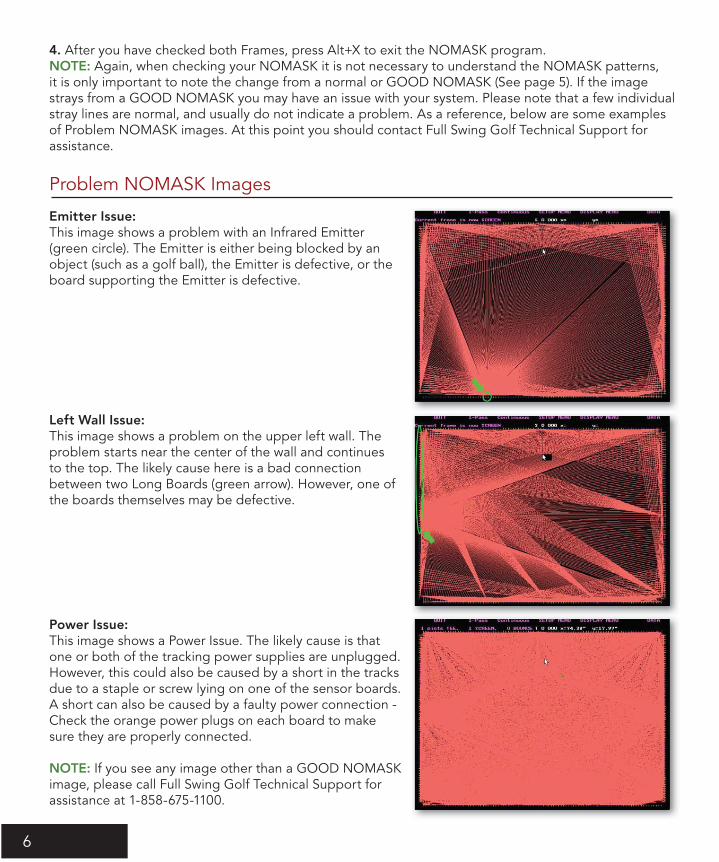
4. After you have checked both Frames, press Alt+X to exit the NOMASK program.NOTE: Again, when checking your NOMASK it is not necessary to understand the NOMASK patterns, it is only important to note the change from a normal or GOOD NOMASK (See page 5). If the image strays from a GOOD NOMASK you may have an issue with your system. Please note that a few individual stray lines are normal, and usually do not indicate a problem. As a reference, below are some examples of Problem NOMASK images. At this point you should contact Full Swing Golf Technical Support for assistance.
Emitter Issue:This image shows a problem with an Infrared Emitter (green circle). The Emitter is either being blocked by an object (such as a golf ball), the Emitter is defective, or the board supporting the Emitter is defective.
Left Wall Issue:This image shows a problem on the upper left wall. The problem starts near the center of the wall and continues to the top. The likely cause here is a bad connection between two Long Boards (green arrow). However, one of the boards themselves may be defective.
Power Issue:This image shows a Power Issue. The likely cause is that one or both of the tracking power supplies are unplugged. However, this could also be caused by a short in the tracks due to a staple or screw lying on one of the sensor boards. A short can also be caused by a faulty power connection - Check the orange power plugs on each board to makesure they are properly connected.
NOTE: If you see any image other than a GOOD NOMASK image, please call Full Swing Golf Technical Support for assistance at 1-858-675-1100.
Problem NOMASK Images
maintenanceManual.indd 6 12/22/10 2:03 PM

7
Problem NOMASK Images
Projector Service Information
Full Swing Golf provides projectors from a variety of manufacturers. Each projector has its own warranty program and maintenance schedule. Always refer to your particular projector’s operation and maintenance manual for specific information on service and warranty.
canon 3 yr. parts and labor 120 day lamp 1-800 652-2666 www.usa.canon.com
Panasonic Special 3 yr. parts and labor (requires manual over ride) 90 day lamp 1-888-411-1996 www.panasonic.com
Sanyo 3 yr. parts and labor 90 day lamp 1-888-337-1215 Quick repair www.sanyolcd.com customer support-projectors-link
Sharp 3yr. parts and labor 90 day lamp 1-888-467-4277 www.sharpusa.com
Sony 3yr. parts and labor 90 day lamp 1-877-350-3477 www.sony.com International warranty - Have projector repaired and pay for it at a Sony owned local repair organization. Send copy of paid invoice to TVS for reimbursement by Sony.
MAKE: ________________________________
MODEL: ______________________________ (found on the projector body, Ex: PT-LB50U)
SERIAL #: ______________________________ (found on the projector body, Ex: SG05532xx)
DATE OF PURcHASE: ___________________ (original installation date or projector purchase date)
International customers:Please contact your local Distributor for warranty and service information regarding your particularprojector. Distributor contact information can be found at www.fsgglobal.com
maintenanceManual.indd 7 12/22/10 2:03 PM

8
Projection Screen Replacement
• Before you begin installation of your projection screen, please be sure to install the plastic black end caps to the end of the screen rods
• After threading the fiberglass rods into the sides of the screen, attach a bungee to the rod at each interval along the screen
• Use TWO bungee cords in the grommets at each corner (See diagram below).
• Then attach the bungee cords to the angle-iron on the simulator in the order shown below • Start at #1 and after attaching the bungees in all four corners, remove the three bungees at the top center and realign them as necessary
• Then attach the other groups of bungees in the order listed below
If, at some point, you choose to replace the projection screen due to long-term wear and tear, please follow the instructions below for proper installation.
16 (re-align)
Top of Screen
1716
14
8
12
10 7 11
13
9
15
2 3
4 5
maintenanceManual.indd 8 12/22/10 2:03 PM

9
Projection Screen Replacement Projection Screen Replacement
After hanging the screen, you will need to re-fasten the lower screen fl ap under the carpet. The excessmaterial should be tucked down between the screen and the booth to create a cup formation. This allows forsome give at the bottom of the screen and will prevent ripping or tearing of the seam. By following these instructions, you should be able to keep your screen taut and eliminate or minimize wrinkles and unevenness.
Pull up the carpet and staples from edge of the simulator, closest to the screen. Remove any loose staples.
Fold back the carpet to the edge of the track.
You should have only 2-3 inches (5-7 cm) of fabric left on top of the wood fl oor panel. This will allow the screen to freely move without putting any strain on the lower fl ap.
Lay the lower screen fl ap fl at on the wood. Starting at the center, push the fl ap about 2 inches (5 cm) down toward the lower angle iron, and work your way out to each end.
maintenanceManual.indd 9 12/22/10 2:03 PM

10
Projection Screen Replacement
Staple the remaining 2-3 (5-7 cm) inches of fabric to the wood fl oor panel.
Space the staples 6-8 (15-20 cm) inches apart.
Staple the carpet back down to the wood, again using a staple every 6-8 inches (15-20 cm).
Place the carpet fl ap down over the wood and screen fl ap.
maintenanceManual.indd 10 12/22/10 2:03 PM

Projection Screen Replacement Projection Screen Replacement
Detail shot of one bungee attached to the frame.
maintenanceManual.indd 11 12/22/10 2:03 PM

maintenanceManual.indd 12 12/22/10 2:03 PM