Embed Size (px)
Citation preview

See discussions, stats, and author profiles for this publication at: https://www.researchgate.net/publication/220636950
The Formal Design Model of an Automatic Teller Machine (ATM)
Article in International Journal of Software Science and Computational Intelligence · January 2010
DOI: 10.4018/jssci.2010101907 · Source: DBLP
CITATIONS
47READS
102,653
5 authors, including:
Some of the authors of this publication are also working on these related projects:
Brain Science: Formal Theories and Brain-Inspired Systems View project
Big Data Algebra (BDA) for Data Science and Engineering View project
Yingxu Wang
The University of Calgary
800 PUBLICATIONS 11,998 CITATIONS
SEE PROFILE
Xuhui Li
Wuhan University
47 PUBLICATIONS 282 CITATIONS
SEE PROFILE
All content following this page was uploaded by Yingxu Wang on 17 May 2014.
The user has requested enhancement of the downloaded file.

102 International Journal of Software Science and Computational Intelligence, 2(1), 102-131, January-March 2010
Copyright © 2010, IGI Global. Copying or distributing in print or electronic forms without written permission of IGI Globalis prohibited.
Keywords: ATM, Design Frameworks, Design Reuse, Formal Design Models, Real-Time Systems, RTPA, Software Engineering, Software Science, System Architecture Specification, System Behaviour Specification, UDM, Unified Data Models, Unified Process Models, UPM
INTRODUCTION
The modeling and description of an Automated Teller Machine (ATM) are a typical design case in safety-critical and real-time systems (Laplante, 1977; Hayes, 1985; McDermid, 1991; Corsetti et al., 1991; Liu, 2000; Wang, 2002, 2007). As a real-time control system, the ATM system is characterized by its high degree of complexity, intricate interactions with hardware devices and
The Formal Design Model of an Automatic Teller Machine (ATM)
Yingxu Wang, University of Calgary, Canada
Yanan Zhang, University of Calgary, Canada
Philip C.-Y. Sheu, Wuhan University, China and Univ. of California, Irvine, USA
Xuhui Li, Wuhan University, China
Hong Guo, Coventry University, UK
ABSTRACTAn Automated Teller Machine (ATM) is a safety-critical and real-time system that is highly complicated in design and implementation. This paper presents the formal design, specification, and modeling of the ATM system using a denotational mathematics known as Real-Time Process Algebra (RTPA). The conceptual model of the ATM system is introduced as the initial requirements for the system. The architectural model of the ATM system is created using RTPA architectural modeling methodologies and refined by a set of Unified Data Models (UDMs), which share a generic mathematical model of tuples. The static behaviors of the ATM system are specified and refined by a set of Unified Process Models (UPMs) for the ATM transition processing and system supporting processes. The dynamic behaviors of the ATM system are specified and refined by process priority allocation, process deployment, and process dispatch models. Based on the formal design models of the ATM system, code can be automatically generated using the RTPA Code Generator (RTPA-CG), or be seamlessly transformed into programs by programmers. The formal models of ATM may not only serve as a formal design paradigm of real-time software systems, but also a test bench for the expressive power and modeling capability of exiting formal methods in software engineering.
DOI: 10.4018/jssci.2010101907

International Journal of Software Science and Computational Intelligence, 2(1), 102-131, January-March 2010 103
Copyright © 2010, IGI Global. Copying or distributing in print or electronic forms without written permission of IGI Globalis prohibited.
users, and necessary requirements for domain knowledge. All these factors warrant the ATM system as a complex but ideal design paradigm in large-scale software system design in general and in real-time system modeling in particular.
There is a lack of systematical and detailed documentation of design knowledge and model-ing prototypes of ATM systems and a formal model of them in denotational mathematics and formal notation systems (Wang, 2008a, 2008b). This paper presents the formal design, specifica-tion, and modeling of the ATM system using a denotational mathematics known as Real-Time Process Algebra (RTPA) (Wang, 2002, 2003, 2007, 2008a, 2008c, 2008d). RTPA introduces only 17 meta-processes and 17 process relations to describe software system architectures and behaviors with a stepwise refinement methodology (Wang, 2007, 2008c). According to the RTPA methodology for system modeling and refinement, a software system can be specified as a set of architectural and operational components as well as their interactions. The former is modeled by Unified Data Models (UDMs, also known as the component logical model (CLM)) (Wang, 2008c), which is an abstract model of system hardware interfaces, an internal logic model of hardware, and/or an internal control structure of the system. The latter is modeled by static and dynamic processes using the Unified Process Models (UPMs) (Hoare, 1978, 1985; Bjorner & Jones, 1982; Wang, 2007, 2008c; Wang & King, 2000).
This paper develops a formal design model of the ATM system in a top-down approach on the basis of the RTPA methodology. This work demonstrates that the ATM system can be for-mally modeled and described by a set of real-time processes in RTPA. In the remainder of this paper, the conceptual model of the ATM system is described as the initial requirements for the system. The architectural model of the ATM system is created based on the conceptual model using the RTPA architectural modeling methodologies and refined by a set of UDMs. Then, the static behaviors of the ATM system are specified and refined by a set of processes (UPMs). The dynamic behaviors of the ATM system are specified and refined by process priority allocation, process deployment, and process dispatching models. With the formal and rigorous models of the ATM system, code can be automatically generated by the RTPA Code Generator (RTPA-CG) (Wang, 2007), or be seamlessly transferred into program code manually. The formal models of ATM may not only serve as a formal design paradigm of real-time software systems, but also a test bench for the expressive power and modeling capability of existing formal methods in software engineering.
THE CONCEPTUAL MODEL OF THE ATM SySTEM
An ATM system is a real-time front terminal of automatic teller services with the support of a central bank server and a centralized account database. This paper models an ATM that provides money withdraw and account balance management services. The architecture of the ATM sys-tem, as shown in Figure 1, encompasses an ATM processor, a system clock, a remote account database, and a set of peripheral devices such as the card reader, monitor, keypad, bills storage, and bills disburser.
The conceptual model of an ATM system is usually described by a Finite State Machine (FSM), which adopts a set of states and a set of state transition functions modeled by a transition diagram or a transition table to describe the basic behaviors of the ATM system. On the basis of the conceptual model of the ATM system as given in Figure 1, the top level behaviors of ATM can be modeled in a transition diagram as shown in Figure 2.
Corresponding to the transition diagram of the ATM as given in Figure 2, a formal model of the ATM system as an FSM, ATMST, is defined as a 5-tuple as follows:

104 International Journal of Software Science and Computational Intelligence, 2(1), 102-131, January-March 2010
Copyright © 2010, IGI Global. Copying or distributing in print or electronic forms without written permission of IGI Globalis prohibited.
ATMST A (S, ∑, s, F, δ) (1)
where
• S is a set of valid states that forms the domain of the ATM, S = {s0, s1, …, s7} where the states are: s0 – System, s1 – Welcome, s2 - Check PIN, s3 – Input withdraw amount, s4 - Verify bal-ance, s5 - Verify bills availability, s6 - Disburse bills, and s7 - Eject card, respectively;
• ∑ is a set of events that the ATM may accept and process, ∑ = {e0, e1, …, e10} where e0 - Start, e1 - Insert card, e2 - Correct PIN, e3 - Incorrect PIN, e4 – Request ≤ max, e5 – Request > max, e6 - Cancel transaction, e7 - Sufficient funds, e8 - Insufficient funds, e9 - Sufficient bills in ATM, and e10 - Insufficient bills in ATM;
• s is the start state of the ATM, s = s1 (Welcome);• F is a set of ending states, F = {s1};• δ is the transition function of the ATM that determines the next state of the FSM, si+1, on the
basis of the current state si and a specific incoming event ei, i.e., si+1 = δ (si, ei), where
δ = f: S × ∑ → S (2)
which can be rigorously defined in the transition table as shown in Table 1 corresponding to the conceptual model of the ATM behaviors as shown in Figure 2.
Based on the above conceptual models and descriptions, an abstract FSM model of the ATM system can be described as shown in Figure 3.
The top level framework of the ATM system can be modeled by a set of architecture, static behaviors, and dynamic behaviors using RTPA (Wang, 2002, 2008a) as follows:
Figure 1. The conceptual model of the ATM system

International Journal of Software Science and Computational Intelligence, 2(1), 102-131, January-March 2010 105
Copyright © 2010, IGI Global. Copying or distributing in print or electronic forms without written permission of IGI Globalis prohibited.
§(ATM) ATM§.ArchitectureST || ATM§.StaticBehaviorsPC || ATM§.DynamicBehaviorsPC (3)
Figure 2. The transition diagram of the ATM behaviors
Table 1. The state transition table of the ATM
si ei si+1 = δ(si, ei)
s0 s1 s2 s2 s2 s3 s3 s3 s4 s4 s5 s5 s6 s7
e0 e1 e2 e3 e6 e4 e5 e6 e7 e8 e9 e10 - -
s1 s2 s3 s2 s7 s4 s3 s7 s5 s7 s6 s7 s7 s1

106 International Journal of Software Science and Computational Intelligence, 2(1), 102-131, January-March 2010
Copyright © 2010, IGI Global. Copying or distributing in print or electronic forms without written permission of IGI Globalis prohibited.
where || indicates that these three subsystems related in parallel, and §, ST, and PC are type suf-fixes of system, system structure, and process, respectively.
The conceptual models of ATM as presented in Figs. 1 through 3 describe the configuration, basic behaviors, and logical relationships among components of the ATM system. According to the RTPA methodology for system modeling, specification, and refinement (Wang, 2008a, 2008b), the top level model of any system may be specified in a similar structure as given in Eq. 3. The following sections will extend and refine the top level framework of ATM§ into detailed architectural models (UDMs) and behavioral models (UPMs).
THE ARCHITECTURAL MODEL OF THE ATM SySTEM
The architecture of a hybrid hardware/software system, particularly a real-time system, is a system framework that represents the overall structure, components, processes, and their in-terrelationships and interactions. This sections specifies the architecture of the ATM system, ATM§.ArchitectureST, by a high-level architectural framework based on its conceptual model as provided in Figure 1. Then, each of its architectural components will be refined as a UDM (also known as Component Logical Model (CLM)) (Wang, 2002, 2007, 2008c).
The Architectural Framework of the ATM System
System architectures, at the top level, specify a list of structural identifiers of UDMs and their relations. A UDM may be regarded as a predefined class of system hardware or internal control
Figure 3. The abstract FSM model of the ATM behaviors

International Journal of Software Science and Computational Intelligence, 2(1), 102-131, January-March 2010 107
Copyright © 2010, IGI Global. Copying or distributing in print or electronic forms without written permission of IGI Globalis prohibited.
models, which can be inherited or implemented by corresponding UDM objects as specific instances in the succeeding architectural refinement processes for the system.
Corresponding to the conceptual model of ATM as shown in Figs. 1 to 3, the high-level speci-fication of the architecture of ATM, ATM§.ArchitectureST, is given in Figure 4 in RTPA. ATM§.ArchitectureST encompasses parallel structures of a set of UDMs such as the ATMProcessorST, CardReaderST, KeypadST, MonitorST, BillStorageST, BillsDisburserST, AccountDatabaseST, and SysClockST, as well as a set of system events @EventsS and a set of statuses &StatusBL. The numbers in the angel brackets indicate the configuration of how many data objects that share the same UDM.
The set of events of ATM are predefined global control variables of the system, as given in Eq. 4, which represent an external stimulus to a system or the occurring of an internal change of status such as an action of users, an updating of the environment, and a change of the value of a control variable. Types of general events, @EventS, that may trigger a behavior in a system can be classified into operational (@eS), time (@tTM), and interrupt (@int) events where @ is the event prefix, and S, TM, and the type suffixes of string, time, and interrupt, respectively, i.e.:
ATM§.ArchitectureST.EventsST @SysInitialS | @tTM = §thh:mm:ss | @SysClock100msInt (4)
In RTPA, a status denoted by sBL is an abstract model of system state in Boolean type with a status prefix , such as an operation result and an internal condition. The ATM statuses as a set of predefined global control variables are as follows:
ATM§.ArchitectureST.StatusST CardReadStatusBL | MonitorStatusBL | KeypadStatusBL | BillStorageStatusBL | BillsDisburserStatusBL | BillsDisburseEngineStatusBL | BillsAvailableBL | BillsDisbursedBL | CardInsertedBL | CardEjectedBL | CancellKeyPressedBL | EnterKeyPressedBL | DataEnteredBL | TimeOutBL | ServiceCompletedBL | ServiceCancelledBL | SystemFailureBL | SysShutDownBL | ValidAmountBL | ValidBalanceBL | ValidCardBL | ValidPINBL (5)

108 International Journal of Software Science and Computational Intelligence, 2(1), 102-131, January-March 2010
Copyright © 2010, IGI Global. Copying or distributing in print or electronic forms without written permission of IGI Globalis prohibited.
The UDM Structures of the ATM System
As modeled in Figure 4, the ATM system encompasses eight UDMs for modeling the system hardware interfaces and internal control structures. It is recognized that UDMs are a powerful modeling means in system architectural modeling (Wang, 2002, 2007, 2008c), which can be used to unify user defined complex data objects in system modeling, and to represent the abstraction and formalization of domain knowledge and structural information. The generic mathematical model of UDMs is tuples. Each of the eight UDMs of the ATM system is designed and modeled in the following subsections, except that the ATMProcessorST will be embodied by its static and dynamic behavioral models (UPMs) in other sections.
a. The UDM of the Card Reader
The card reader of the ATM system, CardReaderST, is an architectural model of the interface device, which accepts an inserted bank card, scans predesigned identification information on the card, and returns the card to users. The UDM model of CardReaderST specifies seven functional fields as shown in Figure 5. The card input port is an input structure consisting of two fields known as the CardInputAddressH and CardInputN. The card insert port is an output structure consisting of two fields known as the CardInsertAddressH and CardInsertEngineBL. The card eject port is another output structure consisting of two fields known as the CardEjectAddressH and CardEjectEngineBL. There are three CardReaderST operating statuses modeled in the fields of CardReadStatusBL, CardInsertStatusBL, and CardEjectStatusBL.
b. The UDM of the Keypad
The keypad of the ATM system, KeypadST, is an architectural model of the interface device for users entering required information such as the personal identification number (PIN) and withdraw amount of money. The UDM model of KeypadST specifies five functional fields with certain design constraints as shown in Figure 6. The field of PortAddressH represents the physi-cal input address of the keypad. The field of InputDigitsH represents information (≤ 4 digits) entered from the keypad. The field of KeypadStatusBL represents the working conditions of the keypad. The fields of EnterPressedBL and CancelPressedBL represent a valid or invalid input entered by the keypad, respectively.
Figure 4. The architectural framework of the ATM system

International Journal of Software Science and Computational Intelligence, 2(1), 102-131, January-March 2010 109
Copyright © 2010, IGI Global. Copying or distributing in print or electronic forms without written permission of IGI Globalis prohibited.
c. The UDM of the Monitor
The monitor of the ATM system, MonitorST, is an architectural model of the output device that displays system operational and status information to users. The UDM model of MonitorST specifies four functional fields with certain design constraints as shown in Figure 7. The field of PortAddressH represents the physical output address to the monitor. The field of OutputIn-formationS represents a string of letters (≤ 255 characters) that will be displayed on the monitor. The field of MonitorStatusBL represents the operational conditions of the monitor. The field of CurrentDisplyS is a system feedback of the latest output information on the monitor.
d. The UDM of the Bills Storage
The bills storage of the ATM system, BillStorageST, is an architectural model of the internal device that stores bills in different notes, which can be sent to the bills disburser in various com-binations. The UDM model of BillStorageST specifies six functional fields with certain design constraints as shown in Figure 8. The bills storage port is an output structure consisting of two fields known as the BillStorageAddressH and BillsAmountN. The bills deliver port is an output structure consisting of two fields known as the BillsDeliverAddressH and BillsDeliverEngineBL. The field of BillStorageStatusBL represents the operational conditions of the bills storage. The field of BillsLevelN represents the current level of bills in the bills storage.
Figure 6. The refined UDM model of the keypad
Figure 5. The refined UDM model of the card reader

110 International Journal of Software Science and Computational Intelligence, 2(1), 102-131, January-March 2010
Copyright © 2010, IGI Global. Copying or distributing in print or electronic forms without written permission of IGI Globalis prohibited.
e. The UDM of the Bills Disburser
The bills disburser of the ATM system, BillsDisburserST, is an architectural model of the output device that delivers bills of requested amount from the bills storage to the customer. The UDM model of BillsDisburserST specifies four functional fields with certain design constraints as shown in Figure 9. The disburser drive port is an output structure consisting of two fields known as the DisburserDriveAddressH and DisburseEngineBL. The field of BillsDisburserStatusBL represents the operational conditions of the bills disburser. The field of AmountDisbursedN is a system feedback signal of bills disbursed to the customer in the current transaction.
f. The UDM of the System Clock
The system clock of the ATM system is an architectural model for event timing, process dura-tion manipulation, and system synchronization. The UDM model of the system clock, Sys-ClockST, is designed as given in Figure 10. SysClockST provides an absolute (calendar) clock CurrentTimehh:mm:ss as the logical time reference of the entire system and a relative clock §tN as a generic counter of the ATM system. The InterruptCounterN is adopted to transfer the system timing ticks at 100ms interval into the second signal. The real-time system clock is up-dated by the process SysClockPC, which will be described in the following section on system static behaviors.
g. The UDM of the System Database
The system database of the ATM system, SysDatabaseST, is an architectural model of the internal centralized database located in the bank`s server where the ATM connects to. The ATM uses the card number scanned from a bank card and the PIN entered from the keypad to access the system database in order to verify the validity of the card and information recorded in the corresponding account in SysDatabaseST, such as the card holder, current balance, and withdraw constraints.
Figure 7. The refined UDM model of the monitor
Figure 8. The refined UDM model of the bills storage

International Journal of Software Science and Computational Intelligence, 2(1), 102-131, January-March 2010 111
Copyright © 2010, IGI Global. Copying or distributing in print or electronic forms without written permission of IGI Globalis prohibited.
The UDM model of SysDatabaseST specifies a set of accounts with seven functional fields as shown in Figure 11. The field of AccountNumN represents a specific account existed in the system that is corresponding to the number assigned to the bank card. The field of AccountStatusBL represents the current status of an account such as active or inactive in the system. The field of PINH represents a user defined PIN (≤ 4 digits) recorded in the system. The field of CardHolderS records the name of person that holds the account. The field of BalanceN represents the current remaining money in the given account. The field of MaxAllowableWithdrawN represents the limit set by the bank for the given account. The field of CurrentWithdrawN specifies the valid user requested amount of withdraw in the current transaction.
The system architectural models specified in this section provide a set of abstract object models and clear interfaces between system hardware and software. By reaching this point, the co-design of a real-time system can be carried out in parallel by separated hardware and software teams. It is recognized that system architecture specification by the means of UDMs is a fundamental and difficult phase in software system modeling, while conventional formal methods hardly provide any support for this purpose. From the above examples in this subsection, it can be seen that RTPA provides a set of expressive notations for specifying system architectural structures and control models, including hardware, software, and their interactions. On the basis of the system architecture specification and with the work products of system architectural components or UDMs, specification of the operational components of the LDS system as behavioral processes can be carried out directly as elaborated in the following sections.
THE STATIC BEHAVIORAL MODEL OF THE ATM SySTEM
A static behavior is a component-level function of a given system that can be determined before run-time. On the basis of the system architecture specifications and with the UDMs of system
Figure 9. The refined UDM model of the bills disburser
Figure 10. The refined UDM model of the system clock

112 International Journal of Software Science and Computational Intelligence, 2(1), 102-131, January-March 2010
Copyright © 2010, IGI Global. Copying or distributing in print or electronic forms without written permission of IGI Globalis prohibited.
architectural components developed in preceding section, the operational components of the given ATM system and their behaviors can be specified as a set of UPMs as behavioral processes operating on the UDMs.
The static behaviors of the ATM system, ATM§.StaticBehaviorsPC, can be described through operations on its architectural models (UDMs). ATM§.StaticBehaviorsPC encompasses eight transactional processes as given in Eq. 1 and Figures 2 and 3, as well as the support processes SysInitialPC, SysClockPC, and SysDiagnosisPC, in parallel as specified below:
ATM§.StaticBehaviorsPC A SysTransactionProcessesPC | SysSupportProcessesPC= (Welcome(<I:: (PNN)>; <O:: (PNN, AccountNumN, ValidCardBL)>; <UDM:: (CardReaderST, MonitorST, SysDatabaseST, SysClockST)>)PC| CheckPIN(<I:: (PNN, AccountNumN)>; <O:: (PNN, ValidPINBL, ServiceCancelledBL)>; <UDM: (MonitorST, KeypadST, SysDatabaseST, SysClockST)>)PC| InputWithdrawAmount(<I:: (PNN, AccountNumN)>; <O:: (PNN, &ValidAmountBL, ServiceCancelledBL)>; <UDM:: (CardReaderST, MonitorST, KeypadST, SysDatabaseST, SysClockST)>)PC| VerifyBalance(<I:: (PNN, AccountNumN)>; <O:: (PNN, AmountToWithdrawN, ValidBalanceBL, ServiceCancelledBL)>; <UDM:: (MonitorST, KeypadST, SysDatabaseST, SysClockST)>)PC| VerifyBillsAvailability(<I:: (PNN, AccountNumN)>; <O:: (PNN, BillsAvailableBL, ServiceCancelledBL)>; <UDM::(CardReaderST, MonitorST, KeypadST, BillStorageST, SysDatabaseST, Sys-
ClockST))>)PC| DisburseBills(<I:: (PNN, AccountNumN)>; <O:: (PNN, &BillsDisbursedBL, ServiceCompletedBL, ServiceCancelledBL)>; <UDM:: (CardReaderST, MonitorST, KeypadST, BillStorageST, BillsDisburserST, SysDatabaseST, SysClockST)>)PC| EjectCard(<I:: (PNN)>; <O:: (PNN, CardEjectedBL)>; <UDM::(CardReaderST, MonitorST)>)PC| SysFailure(<I:: (PNN)>; <O:: (PNN, SystemFailureBL, &CardEjctedBL, &SysShutDownBL)>; <UDM:: (CardReaderST, MonitorST)>)PC )| (SysInitial (<I:: ()>; <O:: (PNN, AccountNumN, CadInsertedBL, SystemFailureBL)>; <UDM::(All_ATM_
UDMsST)>)PC) | SysClock (<I:: ()>; <O:: ()>; <UDM:: (SysClockST)>) PC | SysDiagnosis(<I:: ()>; <O:: ()>; <UDM:: (All_ATM_UDMsST)>)PC ) (6)
Figure 11. The refined UDM model of the system database

International Journal of Software Science and Computational Intelligence, 2(1), 102-131, January-March 2010 113
Copyright © 2010, IGI Global. Copying or distributing in print or electronic forms without written permission of IGI Globalis prohibited.
The following subsections describe how the ATM static behaviors as specified in Eq. 5 are modeled and refined using the denotational mathematical notations and methodologies of RTPA in term of sets of UPMs for the ATM transaction processes and support processes, respectively.
UPMs of the ATM State Transition Processes
The ATM system encompasses eight transaction processes as specified in Eq. 5, i.e., the Wel-comePC, CheckPINPC, InputWithdrawAmountPC, VerifyBalancePC, VerifyBillsAvailabilityPC, DisburseBillsPC, EjectCardPC, and SysFailurePC processes. The following subsections formally describe the UPMs of the eight ATM state transition processes in RTPA.
a. The UPM of the Welcome Process
The welcome process of the ATM system, WelcomePC, as shown in Figure 12, is the first transi-tion process (PNN = 1) that promotes system welcome information until a card is inserted. The ATM system adopts a transaction process number PNN, 0 ≤ PNN ≤ 8, as a global integer variable to represent the current system state, i.e.: (PNN = 0, System), (PNN = 1, Welcome), (PNN = 2, Check PIN), (PNN = 3, Input withdraw amount), (PNN = 4, Verify balance), (PNN = 5, Verify bills availability), (PNN = 6, Disburse bills), (PNN = 7, Eject card), and (PNN = 8, System failure).
WelcomePC reads account information stored in the card via the card reader’s input port address. The obtained account number, AccountNumN, as a global variable of the system as that of PNN is used to seek if there is a corresponding account in the central database and if its status is active. If so, the card is identified as a valid one and the transaction is transferred to the next process CheckPINPC (PNN = 2). Otherwise, the system will terminate the transaction and eject the invalid card by transferring the current process to EjectCardPC (PNN = 7). A timer, SysClockST.Timerss = 10, is introduced in this process, when a valid card is identified, which requests users to enter a PIN within 10 seconds before a timeout termination is resulted in the following process.
It is noteworthy in the first part of the WelcomePC process that a useful safety-critical system design strategy is adopted, in which the key system devices involved are always be checked before a system function is executed. The WelcomePC process checks the conditions of related system devices modeled by the UDMs such as CardReaderST and MonitorST. The functional processes may only go ahead when both of their statuses are normal. Otherwise, exceptional warring message will be generated such as ! (ʻMonitor fault.ʼ) and/or ! (ʻCard reader fault.ʼ).
b. The UPM of the Check PIN Process
The check PIN process of the ATM system, CheckPINPC (PNN = 2), as shown in Figure 13, determines if a valid card matches its PIN. The processes first tests the conditions of related system UDMs operated in this process such as MonitorST and KeypadST, before the functional processes may be carried out. It also checks the 10 second timer set in the preceding process and finds out if a timeout condition has been generated when SysClockST.Timerss = 0, which is updated automatically by the system in the process of SysClockPC.
The CheckPINPC process scans the PIN entered by the user via the keypad of the system. If the PIN is correct and matches the account number, the transaction is transferred to the next process InputWithdrawAmountPC (PNN = 3) after a new 10s timer is set for waiting the customer to enter the requested amount of withdraw. Otherwise, the system will allow the user to retry PIN input up to three times before the transaction is transferred to EjectCardPC (PNN = 7). During the

114 International Journal of Software Science and Computational Intelligence, 2(1), 102-131, January-March 2010
Copyright © 2010, IGI Global. Copying or distributing in print or electronic forms without written permission of IGI Globalis prohibited.
three time trials, if the user gives up by pressing the cancel key, i.e., KeypadST.CancelPressedBL = T, the system will also transfer the transaction to EjectCardPC (PNN = 7).
c. The UPM of the Input Withdraw Amount Process
The input withdraw amount process of the ATM system, InputWithdrawAmountPC (PNN = 3), as shown in Figure 14, captures the user requested amount of withdraw. The processes first tests the conditions of related system UDMs operated in this process such as MonitorST, KeypadST, and CardReaderST, before the functional processes may be carried out. It also checks the 10 second timer set in the preceding process and finds out if a timeout condition has been generated when SysClockST.Timerss = 0.
The InputWithdrawAmountPC process reads the requested amount provided by the user via the keypad of the system. If the amount to withdraw is within the predetermined maximum allow-able limit for the specific account, which is set to be Account(iN)ST.MaxAllowableWithdrawN =
Figure 12. The behavior model of the welcome process

International Journal of Software Science and Computational Intelligence, 2(1), 102-131, January-March 2010 115
Copyright © 2010, IGI Global. Copying or distributing in print or electronic forms without written permission of IGI Globalis prohibited.
$1000 in the system database, the transaction is transferred to the next process CheckBalancePC (PNN = 4). Otherwise, the system will promote the user to reenter a valid withdraw amount. If the user presses ’Yes’ (KeypadST.EnterPressedBL = T) by pressing the Enter key on the keypad, the transaction will remain in the same process with a newly set 10s timer. However, if the user
Figure 13. The behavior model of the check PIN process

116 International Journal of Software Science and Computational Intelligence, 2(1), 102-131, January-March 2010
Copyright © 2010, IGI Global. Copying or distributing in print or electronic forms without written permission of IGI Globalis prohibited.
presses ’No’ (KeypadST.CancelPressedBL = T) by pressing the Enter key on the keypad, the transaction will be transferred to EjectCardPC (PNN = 7).
d. The UPM of the Verify Balance Process
The verify balance process of the ATM system, VerifyBalancePC (PNN = 4), as shown in Figure 15, determines if the current balance of the account is enough for the withdraw request obtained in the preceding process. VerifyBalancePC first tests the conditions of related system UDMs operated in this process such as MonitorST and KeypadST, before the functional processes may be carried out.
The VerifyBalancePC process checks if the requested withdraw amount is less or equal to the current balance of the account maintained in the central database. If so, the transaction is transferred to the next process VerifyBillsAvailabilityPC (PNN = 5). Otherwise, the system will promote the customer to choose either to reenter a smaller amount (KeypadST.EnterPressedBL = T) or give up (KeypadST.CancelPressedBL = T). The former will result in the transaction being transferred to the amount reenter, i.e., PNN = 3, after a new timer is set for limiting the waiting time for entering the new requested amount of withdraw; However, the latter will result in the termination of the current transaction, i.e., PNN = 7.
e. The UPM of the Verify Bills Availability Process
The verify bills availability process of the ATM system, VerifyBillsAvailabilityPC (PNN = 5), as shown in Figure 16, checks if the bills are available in the ATM that meet the demanded withdraw. The processes first tests the conditions of related system UDMs operated in this process such as CardReaderST, MonitorST, KeypadST, and BillStorageST, before the functional processes may be carried out.
The VerifyBillsAvailabilityPC process checks the bills level in the bills storage. If the bills level is higher than the valid withdraw amount, BillStorageST.BillsLevelN ≥ Amount-ToWithdrawN, the system will transfer the current transaction to DisburseBillsPC (PNN = 6) process. Otherwise, the system will find out if the customer wishes to reenter a lower amount by promoting a system message on the monitor and wait for 3 seconds for response. When the customer selects ’Yes’ by pressing the Enter key on the keypad, the system will transfer the cur-rent process back to InputWithdrawAmountPC (PNN = 3), in order to obtaining a new amount for withdraw. However, if the customer selects ’No’ by pressing the Cancel key on the keypad or there was no action after 3 seconds, the system will terminate the transaction by transferring it to EjectCardPC (PNN = 7).
f. The UPM of the Disburse Bills Process
The disburse bills process of the ATM system, DisbureseBillsPC (PNN = 6), as shown in Figure 17, delivers the requested and validated amount of bills from the bills storage to the customer. The process first tests the conditions of related system UDMs operated in this process such as MonitorST, KeypadST, CardreaderST, BillStorageST, and BillsDisburserST, before the functional processes may be carried out.
The DisbureseBillsPC process deducts the balance in the corresponding account, updates the bills level in the bills storage, prepares the exact amount of bills as requested in the bills storage, and deliver them via the output device of the bills disburser. Then, the transaction is successfully completed and is transferred to the next process EjectCardPC (PNN = 7). When bills disburse cannot be carried out because a bill disburser malfunction, the process will promote a

International Journal of Software Science and Computational Intelligence, 2(1), 102-131, January-March 2010 117
Copyright © 2010, IGI Global. Copying or distributing in print or electronic forms without written permission of IGI Globalis prohibited.
Figure 14. The behavior model of the input withdraw amount process

118 International Journal of Software Science and Computational Intelligence, 2(1), 102-131, January-March 2010
Copyright © 2010, IGI Global. Copying or distributing in print or electronic forms without written permission of IGI Globalis prohibited.
system failure information, and the transaction is terminated after the system is transferred to the exception state SysFailurePC (PNN = 8).
g. The UPM of the Eject Card Process
The eject card process of the ATM system, EjectCardPC (PNN = 7), as shown in Figure 18, ter-minates a complete or exceptional transaction, returns the inserted card, and prepares for next service. The process first tests the conditions of related system UDMs operated in this process such as MonitorST and CardreaderST, before the functional processes may be carried out.
There are five designated causes that drive a transaction of the ATM system into the state EjectCardPC, i.e., &ServiceCompletedBL = T, &ServiceCancelledBL = T, &TimeOutBL = T,
Figure 15. The behavior model of the verify balance process

International Journal of Software Science and Computational Intelligence, 2(1), 102-131, January-March 2010 119
Copyright © 2010, IGI Global. Copying or distributing in print or electronic forms without written permission of IGI Globalis prohibited.
&ValidCardBL = F, and &ValidPINBL = F. Except the first condition, all other conditions are due to an operational exception. Therefore, the EjectCardPC process is designed as a switch structure where a different causal event corresponding to different actions before the system returns to WelcomePC (PNN = 1). However, when an unknown cause results in transaction termination, the system will provide a warring information and transfers to SystemFailurePC (PNN = 8).
Figure 16. The behavior model of the verify bill availability process

120 International Journal of Software Science and Computational Intelligence, 2(1), 102-131, January-March 2010
Copyright © 2010, IGI Global. Copying or distributing in print or electronic forms without written permission of IGI Globalis prohibited.
h. The UPM of the System Failure Process
The system failure process of the ATM system, SysFailurePC (PNN = 8), as shown in Figure 19, terminates the system in order to handle an exceptional problem by system maintainers. The SysFailurePC process ejects any card remaining in the machine, provides a warring message on the monitor, and instructs the system dispatching process as shown in Figure 24 to shut down system interactions to customers until it is recovered by maintainers.
UPMs of the ATM Support Processes
In addition to the transaction processing processes of the ATM system as modeled and described in the preceding subsections, a set of system support processes is required for ATM in order to provide necessary system functions. The support processes of the ATM system as specified in Eq. 5 encompass three UPMs such as the SysInitialPC, SysClockPC, and SysDiagnosisPC processes. The following subsections formally describe the refined UPMs of the ATM support processes in RTPA.
Figure 17. The behavior model of the disburse bills process

International Journal of Software Science and Computational Intelligence, 2(1), 102-131, January-March 2010 121
Copyright © 2010, IGI Global. Copying or distributing in print or electronic forms without written permission of IGI Globalis prohibited.
a. The UPM of the System Initialization Process
System initialization is a common process of a real-time system that boots the system, sets its initial states and environment, and preassigns the initial values of data objects of the system such as variables, constants, as well as architectural (hardware interface) and control (internal) UDMs. Initialization is crucially important for a real-time system as well as its control logic specified in the functional processes. The system initialization process of the ATM system, SysInitialPC, is modeled as a UPM in RTPA as shown in Figure 20, where all system architectural and control
Figure 18. The behavior model of the eject card process

122 International Journal of Software Science and Computational Intelligence, 2(1), 102-131, January-March 2010
Copyright © 2010, IGI Global. Copying or distributing in print or electronic forms without written permission of IGI Globalis prohibited.
UDMs are initialized as specified in their UDMs. Then, the system clock and timing interrupt are set to their initial logical or calendar values. However, the system central database, SysDa-tabaseST, is initialized and maintained by the system server of the bank.
b. The UPM of the System Clock Process
The system clock process is a generic support process of a real-time system that maintains and updates an absolute (calendar) clock and a relative clock for the system. The system clock pro-cess of the ATM system, SysClockPC, is modeled in Figure 21. The source of the system clock is obtained from the 100ms interrupt clock signal generated by system hardware, via which the absolute clock with real-time second, minute, and hour, SysClockST.CurrentTimehh:mm:ss, are generated and periodically updated. The second clock in a real-time system is the relative clock, SysClockST.§tN, which is usually adopted for relative timing and duration manipulations. The relative clock is reset to zero at midnight each day in order to prevent it from overflow.
c. The UPM of the System Diagnosis Process
The system diagnosis process of the ATM system, SysDiagnosisPC, as shown in Figure 22 (a) and (b), is a built-in system diagnosis component that is triggered every hour on the hour when there is no current service. The dispatching mechanism of the system diagnosis process is specified at the base-level of system process deployment in Figure 24. SysDiagnosisPC tests all system devices such as the card reader, keypad, monitor, bills storage, and bills disburser. Testing results are diagnosed in order to update the current system operating conditions modeled by a set of global system statuses as shown as part of Eq. 5. It is noteworthy that the built-in-tests (BITs) technol-ogy (Wang et al., 2000) adopted in the ATM system diagnosis process may be further enhanced by additional manual tests regularly conducted by maintainers because many sophisticated tests for the ATM system need interactive operations and feedback of human operators.
Figure 19. The behavior model of the system failure process

International Journal of Software Science and Computational Intelligence, 2(1), 102-131, January-March 2010 123
Copyright © 2010, IGI Global. Copying or distributing in print or electronic forms without written permission of IGI Globalis prohibited.
THE DyNAMIC BEHAVIORAL MODEL OF THE ATM SySTEM
Dynamic behaviors of a system are run-time process deployment and dispatching mechanisms based on the static behaviors modeled in UPMs. Because the static behaviors are a set of com-ponent processes of the system, to put the static processes into a life and interacting system at
Figure 21. The behavior model of the system clock process
Figure 20. The behavior model of the system initialization process

124 International Journal of Software Science and Computational Intelligence, 2(1), 102-131, January-March 2010
Copyright © 2010, IGI Global. Copying or distributing in print or electronic forms without written permission of IGI Globalis prohibited.
run-time, the dynamic behaviors of the system in terms of process priority allocation, process deployment, and process dispatch, are yet to be specified. With the UPMs developed in the pre-ceding section as a set of static behavioral processes of the ATM system, this section describes the dynamic behaviors of the ATM system at run-time via process priority allocation, process deployments, and process dispatch.
Figure 22.
(a) The behavior model of the system diagnosis process

International Journal of Software Science and Computational Intelligence, 2(1), 102-131, January-March 2010 125
Copyright © 2010, IGI Global. Copying or distributing in print or electronic forms without written permission of IGI Globalis prohibited.
Figure 22. continued
(b) The behavior model of the system diagnosis process

126 International Journal of Software Science and Computational Intelligence, 2(1), 102-131, January-March 2010
Copyright © 2010, IGI Global. Copying or distributing in print or electronic forms without written permission of IGI Globalis prohibited.
Process Priority Allocation of the ATM System
The process priority allocation of system dynamic behaviors is the executing and timing re-quirements of all static processes at run-time. In general, process priorities can be specified at 4 levels for real-time and nonreal-time systems in an increasing priority known as: L1: base level processes, L2: high level processes, L3: low interrupt level processes, and L4: high interrupt level processes. The L1 and L2 processes are system dynamic behaviors that are executable in normal sequential manner. However, the L3 and L4 processes are executable in periodical man-ner triggered by certain system timing interrupts. It is noteworthy that some of the priority levels may be omitted in modeling a particular system, except the base level processes. That is, any system encompasses at least a base level process, particularly for a nonreal-time or transaction processing system.
According to the RTPA system modeling and refinement methodology (Wang, 2007), the first step refinement of the dynamic behaviors of the ATM system known as process priority allocation can be specified as shown in Figure 23. It may be observed that all non-periodical processes at run-time including SysInitialPC, SysDiagnosisPC, and the 8 transaction processes such as WelcomePC, CheckPINPC, InputWithdrawAmountPC, VerifyBalancePC, VerifyBills AvailabilityPC, DisburseBillsPC, EjectCardPC, and SysFailurePC, are allocated at the base level (L1). Therefore, there is no high level process in the ATM system. However, the process with strict timing constraints, SysClockPC, is allocated as periodical interrupt processes at L3.
Process Deployment of the ATM System
Process deployment is a dynamic behavioral model of systems at run-time, which refines the timing relations and interactions among the system (§), system clock, system interrupts, and all processes at different priority levels. Process deployment is a refined model of process priority allocation for time-driven behaviors of a system. On the basis of the process priority allocation model as developed in previous subsection in Figure 23, the ATM dynamic behaviors can be
Figure 23. Process priority allocation of ATM dynamic behaviors

International Journal of Software Science and Computational Intelligence, 2(1), 102-131, January-March 2010 127
Copyright © 2010, IGI Global. Copying or distributing in print or electronic forms without written permission of IGI Globalis prohibited.
further refined with a process deployment model as shown in Figure 24, where precise timing relationships between different priority levels are specified.
The dynamic behaviors of the ATM system can be described by the interactions of parallel categories of processes at the base and interrupt levels triggered by the event @SystemInitialS or @SysClockl00msInst, respectively. The ATM system repeatedly executes the eight transaction processes at base level until the event SysShutDownBL = T is captured by the system (§). The system diagnosis process, SysDiagnosisPC, is also deployed at the base level, which is triggered every hour on the hour when the system is idle, i.e., PNN = 1.
When the interrupt-level process occurs per 100ms during run-time of base level processes, the system switches priority scheduling to the interrupt level process SysClockPC. Once it is completed, the interrupt-level process hands over control to the system in order to resume the interrupted base-level functions.
Process Dispatch of the ATM System
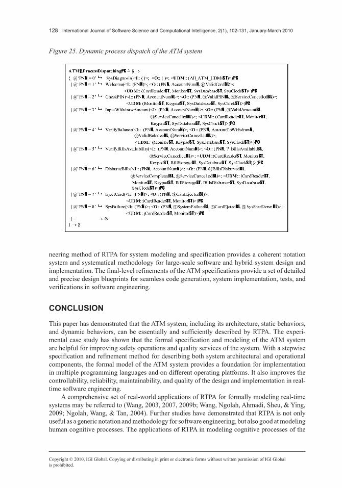
Process dispatch is a dynamic behavioral model of systems at run-time, which refines relations between system events and processes. Dynamic process dispatch specifies event-driven behaviors of a system. In the ATM system, the iterative transaction processing processes, ATM§.Transac-tionProcessesPC, are a complex process that can be further refined in a system process dispatching framework as shown in Figure 25. The ATM process dispatching model specifies that the system iteratively handles transaction processes by a switch structure. In a certain process, one of the eight possible transaction processes determined by the value of current process numbers of the system (PNN) is dispatched. Then, the dispatch process returns control to the system (§).
The formal design models of the ATM system and their refinements demonstrate a typical system modeling paradigm of the entire architectures, static behaviors, and dynamic behaviors according to the RTPA specification and refinement methodology. The practical formal engi-
Figure 24. Dynamic process deployment of the ATM system
128 International Journal of Software Science and Computational Intelligence, 2(1), 102-131, January-March 2010
Copyright © 2010, IGI Global. Copying or distributing in print or electronic forms without written permission of IGI Globalis prohibited.
neering method of RTPA for system modeling and specification provides a coherent notation system and systematical methodology for large-scale software and hybrid system design and implementation. The final-level refinements of the ATM specifications provide a set of detailed and precise design blueprints for seamless code generation, system implementation, tests, and verifications in software engineering.
CONCLUSION
This paper has demonstrated that the ATM system, including its architecture, static behaviors, and dynamic behaviors, can be essentially and sufficiently described by RTPA. The experi-mental case study has shown that the formal specification and modeling of the ATM system are helpful for improving safety operations and quality services of the system. With a stepwise specification and refinement method for describing both system architectural and operational components, the formal model of the ATM system provides a foundation for implementation in multiple programming languages and on different operating platforms. It also improves the controllability, reliability, maintainability, and quality of the design and implementation in real-time software engineering.
A comprehensive set of real-world applications of RTPA for formally modeling real-time systems may be referred to (Wang, 2003, 2007, 2009b; Wang, Ngolah, Ahmadi, Sheu, & Ying, 2009; Ngolah, Wang, & Tan, 2004). Further studies have demonstrated that RTPA is not only useful as a generic notation and methodology for software engineering, but also good at modeling human cognitive processes. The applications of RTPA in modeling cognitive processes of the
Figure 25. Dynamic process dispatch of the ATM system
International Journal of Software Science and Computational Intelligence, 2(1), 102-131, January-March 2010 129
Copyright © 2010, IGI Global. Copying or distributing in print or electronic forms without written permission of IGI Globalis prohibited.
brain and computational intelligence may be referred to (Wang, 2009a, 2009c; Wang & Chiew, in press; Wang & Ruhe, 2007; Wang, Kinsner, & Zhang, 2009; Wang, Zadeh, & Yao, 2009).
ACKNOWLEDGMENT
The authors would like to acknowledge the partial support of Natural Science and Engineering Council of Canada (NSERC) to this work. The authors would like to thank the anonymous review-ers for their invaluable comments that have greatly improved the latest version of this paper.
REFERENCES
Bjorner, D., & Jones, C. B. (1982). Formal specification and software development. Upper Saddle River, NJ: Prentice Hall.
Corsetti, E., Montanari, A., & Ratto, E. (1991). Dealing with different time granularities in formal specifica-tions of real-time systems. Journal of Real-Time Systems, 3(2), 191–215. doi:10.1007/BF00365335
Hayes, I. (1985). Applying formal specifications to software development in industry. IEEE Transactions on Software Engineering, 11(2), 169–178. doi:10.1109/TSE.1985.232191
Hoare, C. A. R. (1978). Communicating sequential processes. Communications of the ACM, 21(8), 666–677. doi:10.1145/359576.359585
Hoare, C. A. R. (1985). Communicating sequential processes. Upper Saddle River, NJ: Prentice-Hall.
Laplante, P. A. (1977). Real-time systems design and analysis (2nd ed.). Washington, DC: IEEE Press.
Liu, J. (2000). Real-time systems. Upper Saddle River, NJ: Prentice-Hall.
McDermid, J. A. (Ed.). (1991). Software engineer’s reference book. Oxford, UK: Butterworth-Heine-mann.
Ngolah, C. F., Wang, Y., & Tan, X. (2004). The real-time task scheduling algorithm of RTOS+. IEEE Canadian Journal of Electrical and Computer Engineering, 29(4), 237–243.
Wang, Y. (2002). The real-time process algebra (RTPA). Annals of Software Engineering, 14, 235–274. doi:10.1023/A:1020561826073
Wang, Y. (2003). Using process algebra to describe human and software system behaviors. Brain and Mind, 4(2), 199–213. doi:10.1023/A:1025457612549
Wang, Y. (2007). Software engineering foundations: A software science perspective. In CRC series in software engineering (Vol. II). Boca Raton, FL: Auerbach Publications.
Wang, Y. (2008a). On contemporary denotational mathematics for computational intelligence. Transactions of Computational Science, 2, 6–29. doi:10.1007/978-3-540-87563-5_2
Wang, Y. (2008b). Mathematical laws of software. Transactions of Computational Science, 2, 46–83. doi:10.1007/978-3-540-87563-5_4
Wang, Y. (2008c). RTPA: A denotational mathematics for manipulating intelligent and computational behaviors. International Journal of Cognitive Informatics and Natural Intelligence, 2(2), 44–62.
Wang, Y. (2008d). Deductive semantics of RTPA. International Journal of Cognitive Informatics and Natural Intelligence, 2(2), 95–121.

130 International Journal of Software Science and Computational Intelligence, 2(1), 102-131, January-March 2010
Copyright © 2010, IGI Global. Copying or distributing in print or electronic forms without written permission of IGI Globalis prohibited.
Wang, Y. (2009a). On abstract intelligence: Toward a unified theory of natural, artificial, machinable, and computational intelligence. International Journal of Software Science and Computational Intelligence, 1(1), 1–17.
Wang, Y. (2009b). The formal design model of a telephone switching system (TSS). International Journal of Software Science and Computational Intelligence, 1(3), 92–116.
Wang, Y. (2009c). On cognitive computing. International Journal of Software Science and Computational Intelligence, 1(3), 1–15.
Wang, Y., & Chiew, V. (2010), On the cognitive process of human problem solving. Cognitive Systems Research: An International Journal, Elsevier, 11(1), 81-92.
Wang, Y., & King, G. (2000). Software engineering processes: Principles and applications. In CRC series in software engineering (Vol. I). Boca Raton, FL: CRC Press.
Wang, Y., King, G., Fayad, M., Patel, D., Court, I., & Staples, G. (2000). On built-in tests reuse in object-ori-ented framework design. ACM Journal on Computing Surveys, 32(1), 7–12. doi:10.1145/351936.351943
Wang, Y., Kinsner, W., & Zhang, D. (2009). Contemporary cybernetics and its faces of cognitive informat-ics and computational intelligence. IEEE Trans. on System, Man, and Cybernetics (B), 39(4), 823–833. doi:10.1109/TSMCB.2009.2013721
Wang, Y., Ngolah, C. F., Ahmadi, H., Sheu, P., & Ying, S. (2009). The formal design model of a lift dis-patching system (LDS). International Journal of Software Science and Computational Intelligence, 1(4), 98–122.
Wang, Y., & Ruhe, G. (2007). The cognitive process of decision making. International Journal of Cognitive Informatics and Natural Intelligence, 1(2), 73–85.
Wang, Y., Zadeh, L. A., & Yao, Y. (2009). On the system algebra foundations for granular computing. International Journal of Software Science and Computational Intelligence, 1(1), 64–86.
Yingxu Wang is professor of cognitive informatics and software engineering, Director of Inter-national Center for Cognitive Informatics (ICfCI), and Director of Theoretical and Empirical Software Engineering Research Center (TESERC) at the University of Calgary. He is a Fellow of WIF, a P.Eng of Canada, a Senior Member of IEEE and ACM, and a member of ISO/IEC JTC1 and the Canadian Advisory Committee (CAC) for ISO. He received a PhD in Software Engineering from The Nottingham Trent University, UK, in 1997, and a BSc in Electrical Engi-neering from Shanghai Tiedao University in 1983. He has industrial experience since 1972 and has been a full professor since 1994. He was a visiting professor in the Computing Laboratory at Oxford University in 1995, Dept. of Computer Science at Stanford University in 2008, and the Berkeley Initiative in Soft Computing (BISC) Lab at University of California, Berkeley in 2008, respectively. He is the founder and steering committee chair of the annual IEEE International Conference on Cognitive Informatics (ICCI). He is founding Editor-in-Chief of International Journal of Cognitive Informatics and Natural Intelligence (IJCINI), founding Editor-in-Chief of International Journal of Software Science and Computational Intelligence (IJSSCI), Associate Editor of IEEE Trans on System, Man, and Cybernetics (A), and Editor-in-Chief of CRC Book Series in Software Engineering. He is the initiator of a number of cutting-edge research fields and/or subject areas such as cognitive informatics, cognitive computing, abstract intelligence,
International Journal of Software Science and Computational Intelligence, 2(1), 102-131, January-March 2010 131
Copyright © 2010, IGI Global. Copying or distributing in print or electronic forms without written permission of IGI Globalis prohibited.
denotational mathematics, theoretical software engineering, coordinative work organization theory, cognitive complexity of software, and built-in tests. He has published over 100 peer reviewed journal papers, 200+ peer reviewed conference papers, and 12 books in cognitive informatics, software engineering, and computational intelligence. He is the recipient of dozens international awards on academic leadership, outstanding contribution, research achievement, best paper, and teaching in the last 30 years.
Yanan Zhang is an MSc candidate in software engineering from at University of Calgary, Canada. She received a BSc degree in computer science from the North Jiaotong University, Beijing, China in 1989. Her main research interests are in software engineering, Internet-based and distributed systems, and real-time process algebra and its applications.
Phillip C-Y. Sheu is currently a professor of computer engineering, information and computer science, and biomedical engineering at the University of California, Irvine. He received his PhD and MSc degrees from the University of California at Berkeley in electrical engineering and computer science in 1986 and 1982, respectively, and his BSs degree from National Taiwan University in electrical engineering in 1978. Between 1982 and 1986, he also worked as a computer scientist at Systems Control Technology, Inc., Palo Alto, CA., where he designed and implemented aircraft expert control systems, and he worked as a product planning engineer at Advanced Micro Devices Inc., Sunnyvale, CA, where he designed and integrated CAD systems. From 1986 to 1988, he was an assistant professor at School of Electrical Engineering, Pur-due University. From 1989 to 1993, he was an associate professor of electrical and computer engineering at Rutgers University. He has published two books: Intelligent Robotic Planning Systems and Software Engineering and Environment - An Object-Oriented Perspective, and more than 100 papers in object-relational data and knowledge engineering and their applications, and biomedical computations. He is currently active in research related to complex biological systems, knowledge-based medicine, semantic software engineering, proactive web technologies, and large real-time knowledge systems for defense and homeland security. His current research projects are sponsored by the National Science Foundation, National Institute of Health, and Department of Defense. Sheu is a Fellow of IEEE.
Xuhui Li received the BSc degree in information science and the MSc and the PhD degrees in computer science from Wuhan University in 1996, 1999, and 2003, respectively. He is currently an associate professor in the State Key Laboratory of Software Engineering, Wuhan University in China. His research interests are programming languages, formal theory, data management and parallel and distributed computing. He is a member of ACM, a member of IEEE and a member of IEEE Computer Society.
Hong Guo is a senior lecturer in software engineering and a member of the Biomedical Computing and Engineering Technologies Applied Research Group (BIOCORE) at Coventry University. She received her PhD from Nottingham Trent University in 2001. She has published many papers in journals and conferences on software quality management, object oriented software engineer-ing, the application of software process assessment improvement in healthcare applications and in Teleworking environments. She is a visiting professor at Beijing Technology and Business University, Beijing, China.
View publication statsView publication stats