Embed Size (px)
Citation preview

www.MyDIYCNC.com
Page 1 of 15 ©MyDIYCNC: Limit Switches Assembly Instructions
Limit Switches Assembly
The following describes how to assemble your DIY Desktop CNC Machine Limit
Switches Kit:
Prep
You will need a copy of the DIY Desktop
CNC Machine Comprehensive Plans &
Manual, a wire cutter (snips/side cutter),
an X-acto knife or scalpel, a crosshead
screwdriver, a 7/64” drill bit and drill, small
cable ties (about 8), electrical tape, a
soldering iron and solder.
Optional items include a wire stripper and
solder flux paste.
When working with
electronic components,
always take the necessary
precautions to avoid static
electricity damage.
1 – Assemble
Parts
Lay out your electronic parts. Press the
switches into position on the mini circuit
boards as indicated on the board in white
print.
www.MyDIYCNC.com
Page 2 of 15 ©MyDIYCNC: Limit Switches Assembly Instructions
2
Solder the switch pins to the underside of
the mini circuit board.
Repeat for all six limit switch mini circuit
boards.
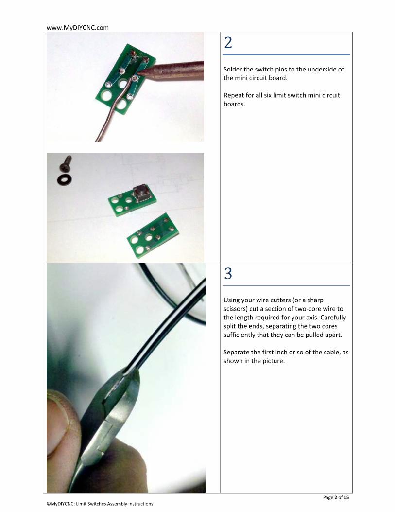
3
Using your wire cutters (or a sharp
scissors) cut a section of two-core wire to
the length required for your axis. Carefully
split the ends, separating the two cores
sufficiently that they can be pulled apart.
Separate the first inch or so of the cable, as
shown in the picture.

www.MyDIYCNC.com
Page 3 of 15 ©MyDIYCNC: Limit Switches Assembly Instructions
4
Using your wire strippers, bare the ends of
the wire. Using your soldering iron, tin the
ends of the wire.
Dipping the ends of the bare wire in solder
paste will help tinning them.
5
Insert the ends of the wire from the
bottom through the two larger strain-relief
holes in the board at the opposite end
from the switch.
The tinned ends should be protruding
through on the side of the switch.

www.MyDIYCNC.com
Page 4 of 15 ©MyDIYCNC: Limit Switches Assembly Instructions
6
Bend the wire ends so that the tinned ends
push through the solder holes nearest the
switch, as shown in the picture.
Solder the wire ends to the solder pads.
7
Using your wire cutters, snip off the
protruding ends of the wires as close as
possible to the solder pad.
8
Your finished limit switch should look like
the one shown in the picture.
Repeat this process for the remaining limit
switches.

www.MyDIYCNC.com
Page 5 of 15 ©MyDIYCNC: Limit Switches Assembly Instructions
9 – Attach to
Machine
Using your carpenter’s square, mark a line
on the inside of each gantry support
upright level with the top of the Y carriage.
Your limit switch needs to be placed below
that mark and in line with the Y carriage
such that the edge of the Y carriage makes
contact with the limit switch before
reaching the gantry support upright.

www.MyDIYCNC.com
Page 6 of 15 ©MyDIYCNC: Limit Switches Assembly Instructions
10
Drill a 7/64” hole at least 1/8” below the
mark you made in step 9.
11
Using the screw and plastic washer
provided, attach the limit switch to the
gantry support upright as shown.
The plastic washer goes between the
screw head and the board.
Repeat for the opposite side of the Y axis.
12
The mounted limit switch should appear as
shown in the pictures.

www.MyDIYCNC.com
Page 7 of 15 ©MyDIYCNC: Limit Switches Assembly Instructions
13 – X Axis
The X axis limit switches both attach to
metal and therefore the surface they
attach to must be insulated from the
solder pads on the back of the mini circuit
board.
Cut a section of electrical tape and stick it
to the protruding face of the X stepper
motor as shown in the pictures.
www.MyDIYCNC.com
Page 8 of 15 ©MyDIYCNC: Limit Switches Assembly Instructions
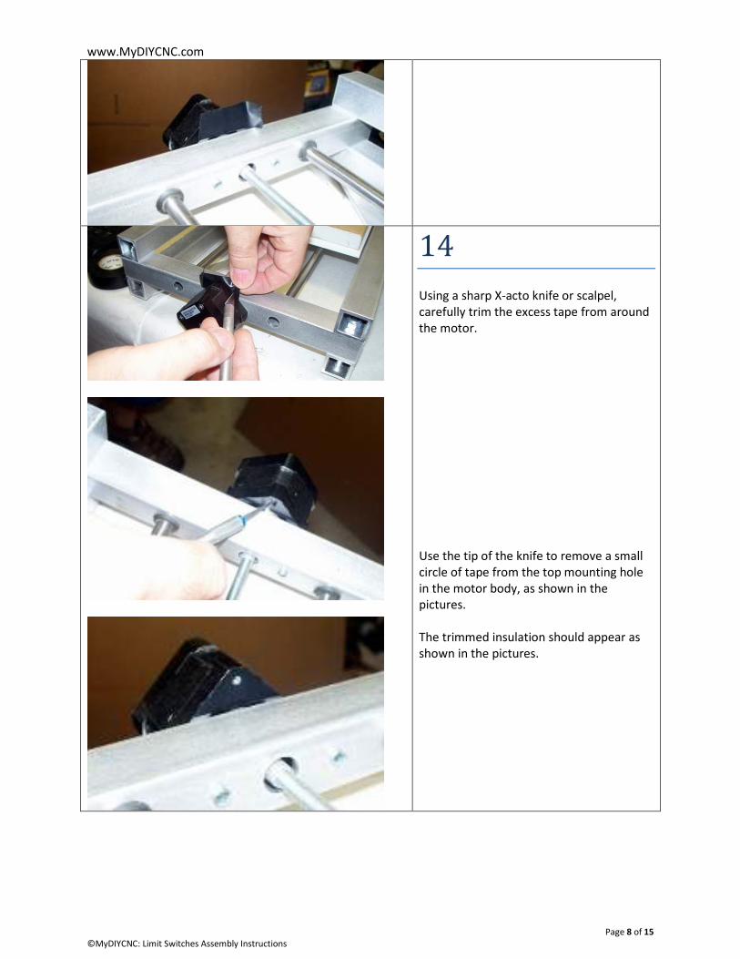
14
Using a sharp X-acto knife or scalpel,
carefully trim the excess tape from around
the motor.
Use the tip of the knife to remove a small
circle of tape from the top mounting hole
in the motor body, as shown in the
pictures.
The trimmed insulation should appear as
shown in the pictures.

www.MyDIYCNC.com
Page 9 of 15 ©MyDIYCNC: Limit Switches Assembly Instructions
15
Using the machine screw provided, thread
the screw through the plastic washer, the
limit switch board and into the top
mounting hole of the stepper motor .
Carefully turn in the screw until snug and
finger-tight. Do not over-tighten as that
could drive the solder pads on the back of
the mini circuit board through the
insulation and into contact with the metal
chassis.
Once mounted, the limit switch should
appear as shown in the pictures.
You may loosen the screw to rotate the
limit switch to get the best alignment with
the edge of the X table.

www.MyDIYCNC.com
Page 10 of 15 ©MyDIYCNC: Limit Switches Assembly Instructions
16 – Z Axis
Position a limit switch on the inside edge
of the Z axis rod mounting blocks, and
mark the mounting hole location with as
pencil, as shown in the pictures.
Do this for both ends of the Z carriage
travel.
17
You will need to use either a compact drill,
or the spindle provided in your MyDIYCNC
kit to make mounting holes in the confined
space.
Drill a 7/64” hole in both Z rod ends
mounting blocks at the locations marked
earlier. A small angle is acceptable on
these holes.

www.MyDIYCNC.com
Page 11 of 15 ©MyDIYCNC: Limit Switches Assembly Instructions
18
Pass the mounting screw provided through
a plastic washer provided and attach the
limit switch assembly to the mounting
hole.
Do this for both ends of the Z carriage
travel.
www.MyDIYCNC.com
Page 12 of 15 ©MyDIYCNC: Limit Switches Assembly Instructions
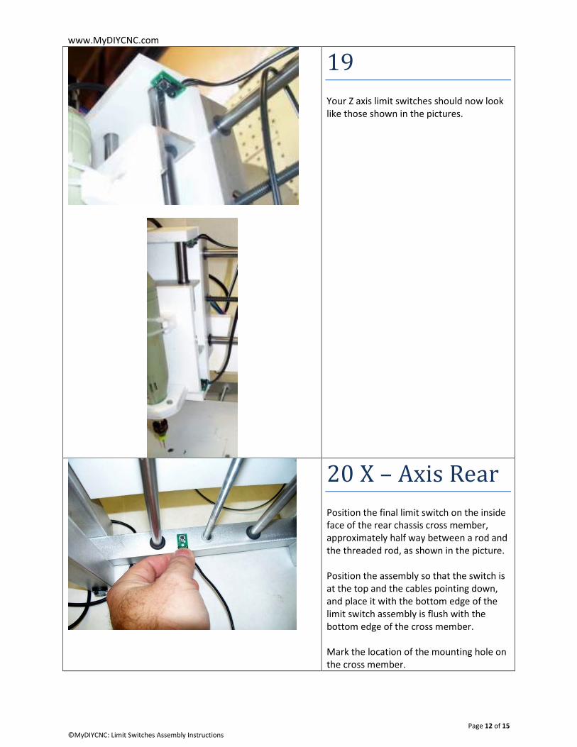
19
Your Z axis limit switches should now look
like those shown in the pictures.
20 X – Axis Rear
Position the final limit switch on the inside
face of the rear chassis cross member,
approximately half way between a rod and
the threaded rod, as shown in the picture.
Position the assembly so that the switch is
at the top and the cables pointing down,
and place it with the bottom edge of the
limit switch assembly is flush with the
bottom edge of the cross member.
Mark the location of the mounting hole on
the cross member.

www.MyDIYCNC.com
Page 13 of 15 ©MyDIYCNC: Limit Switches Assembly Instructions
21
You will need to use either a compact drill,
or the spindle provided in your MyDIYCNC
kit to make a mounting hole in the
confined space.
Drill a 7/64” hole in the rear cross member
at the location marked earlier. A small
angle is acceptable on this holes.
22
Place a piece of electrical tape over the
hole and covering a section of the rear
cross member larger than the limit switch
assembly, as shown in the picture.
Since you will be using the self-threading
screw provided, there is no need to cut a
hole in the electrical tape to expose the
mounting hole, as you did in step 14.
23
Attach the limit switch to the rear cross
member with the screw provided as shown
in the picture.

www.MyDIYCNC.com
Page 14 of 15 ©MyDIYCNC: Limit Switches Assembly Instructions
24 Wiring
Make sure that you have the latest version
of the MyDIYCNC Desktop CNC Machine
Comprehensive Plans & Manual and can
view the wiring diagram.
Bare the ends of the limit switch cables.
Take a moment to plan your cable routing
and layout around your CNC machine. Lay
the cables such that they end up at your
electronics control box.
Take one wire from each limit switch, and
twist them together. Tin the resulting
combined ends. These will become the
ground return line for each switch. If using
heat-shrink tube to insulate the
connection, now is the time to place that
over the cable. Solder the combined
ground lines to one of the free ground
cores in your ribbon cable (connecting the
cable to any pin from number 18 to 25 on
the Db-25 connector). Insulate the
connection.
For each axis, take the remaining two
cables, twist the ends together and tin the
combined end. Solder the combined ends
for that axis to the corresponding ribbon
cable core for that axis’ limit switch, as
shown in the wiring diagram. Insulate the
connections.

www.MyDIYCNC.com
Page 15 of 15 ©MyDIYCNC: Limit Switches Assembly Instructions
25 Test
Within your CNC application, make sure
that it is configured for hardware limit
switches, and that the pin assignments for
each axis’ limit switch matches the
connections you just made and the wiring
diagram.
Your limit switches are “normally-open”
(NO) switches that ground the connection
when pressed. Therefore your CNC
application should expect the limit switch
channel to go “low) (go to ground) when
triggered. If you find that the limit switches
are registering as triggered even though
they are not pressed, use your CNC app’s
settings to invert the logic of the limit
switches.
If your CNC app is set up correctly, pressing
the limit switch on your CNC machine
should instantly prompt a warning and halt
operations. This is easy to test by pressing
any one of the switches.
For technical support and additional resources, please login to your account at www.MyDIYCNC.com