Embed Size (px)
DESCRIPTION
The First Snap Fit Handbook 2005
Citation preview


The First Snap-FitHandbook -
Paul R. Bonenberger
Hanser Publishers, Munich • Hanser Gardner Publications, Cincinnati
2nd Edition
Creating and Managing Attachmentsfor Plastic Parts

Distributed in the USA and in Canada byHanser Gardner Publications, Inc.6915 Valley Avenue, Cincinnati, Ohio 45244-3029, USAFax: (513) 527-8801Phone: (513) 527-8977 or 1-800-950-8977www.hansergardner.com
Distributed in all other countries byCarl Hanser VerlagPostfach 86 04 20, 81631 München, GermanyFax: +49 (89) 98 48 09www.hanser.de
The use of general descriptive names, trademarks, etc., in this publication, even if the former are not especiallyidentified, is not to be taken as a sign that such names, as understood by the Trade Marks and Merchandise MarksAct, may accordingly be used freely by anyone.While the advice and information in this book are believed to be true and accurate at the date of going to press,neither the authors nor the editors nor the publisher can accept any legal responsibility for any errors or omissionsthat may be made. The publisher makes no warranty, express or implied, with respect to the material containedherein.
The Author:Paul R. Bonenberger, 1572 Pebble Creek, Rochester, MI 48307, USA
Library of Congress Cataloging-in-Publication DataBonenberger, Paul R.
The first snap-fit handbook : creating and managing attachments forplastic parts / Paul R. Bonenberger.-- 2nd ed.
p. cm.ISBN 1-56990-388-3
1. Assembly-line methods. 2. Fasteners--Design and construction. 3.Plastics--Molding. 4. Production engineering. I. Title.
TS178.4.B64 2005621.8‘8--dc22
2005015510
Bibliografische Information Der Deutschen Bibliothek:Die Deutsche Bibliothek verzeichnet diese Publikation in der Deutschen Nationalbibliografie;detaillierte bibliografische Daten sind im Internet über <http://dnb.ddb.de> abrufbar.ISBN 3-446-22753-9
All rights reserved. No part of this book may be reproduced or transmitted in any form or by any means, electronicor mechanical, including photocopying or by any information storage and retrieval system, without permission inwirting from the publisher.
© Carl Hanser Verlag, Munich 2005Production Management: Oswald ImmelTypeset by Techset Composition Ltd, Salisbury, UKCoverconcept: Marc Müller-Bremer, Rebranding, München, GermanyCoverdesign: MCP • Susanne Kraus GbR, Holzkirchen, GermanyPrinted and bound by Druckhaus “Thomas Müntzer” GmbH, Bad Langensalza, Germany

Foreword
Over the past decade we have seen a complete redefinition of the expected outcome of
design for manufacture in the product development process. The term, design for
manufacture (DFM), was often applied to a process of using rules or guidelines to assist in
the design of individual parts for efficient processing. For this purpose the rule sets, or lists
of guidelines, were often made available to designers through company specific design
guides. Such information is clearly valuable to design teams who can make very costly
decisions about the design of individual parts if these are made without regard to the
capabilities and limitations of the required manufacturing processes. However, if DFM rules
are used as the main principles to guide a new design in the direction of manufacturing
efficiency, then the result will usually be very unsatisfactory. The end result of this guidance
towards individual part simplicity will often be a product with an unnecessarily large number
of individual functional parts, with a corresponding large number of interfaces between
parts, and with a large number of associated items for connecting and securing. At the
assembly level, as opposed to the manufactured part level, the resulting product will often be
very far from optimal with respect to total cost or reliability.
The alternative approach to part-focused DFM, is to concentrate initially on the structure
of the product and try to reach team consensus on the design structure which is likely to
minimize cost when assembly as well as part manufacturing costs are considered. With this
goal in mind, Design for Assembly (DFA) is now most often the first stage in the design for
manufacture evaluation of a new product concept. The activity of DFA naturally guides the
design team in the direction of part count reduction. DFA challenges the product
development team to reduce the time and cost required for assembly of the product. Clearly,
a powerful way to achieve this result is to reduce the number of parts which must be put
together in the assembly process. DFA is a vehicle for questioning the relationship between
the parts in a design and for attempting to simplify the structure through combinations of
parts or features, through alternative choices of securing methods, or through spatial
relationship changes.
An important role of DFA is to assist in the determination of the most efficient fastening
methods, for the necessary interfaces between separate items in a design. This is an
important consideration since separate fasteners are often the most labor-intensive group of
items when considering mechanical assembly work. To reduce the assembly cost of dealing
with separate fasteners, fastening methods, which are an integral part of functional items,
should always be considered. For plastic molded parts, well-designed snap fits of various
types can provide reliable high-quality fastening arrangements, which are extremely efficient
for product assembly. It is not an overstatement to claim that snap-fitted assembly structures
have revolutionized the manufacturing efficiency of almost all categories of consumer
products.

In this context, The First Snap-Fit Handbook by Paul Bonenberger provides an
extremely valuable resource for product development teams. The concept of complete snap-
fit attachment systems, rather than isolated analyses of the mechanics of the snap-fit
elements, represents a major advance in the design of integral plastic attachment methods.
This concentration on ‘‘attachment level’’ rather than snap-fit ‘‘feature level’’design has been
developed and tested by Paul Bonenberger through years of solving attachment problems
with product development teams at General Motors Corporation. This handbook contains
the best blend of analysis and real-world design experience.
Wakefield, Rhode Island Peter Dewhurst
vi Foreword

Preface to Second Edition
The first edition of this book introduced a systematic way of thinking about snap-fit
attachments. By intent, it did not spend a lot of time or space on calculations of feature
behavior because this information was available elsewhere. That information is still available
in various resources, including on-line sources; therefore, no new calculations have been
added. However, equations for locking feature analysis are available on-line. The reader
should check Appendix A for resources providing snap-fit feature calculations.
This second edition provides the opportunity to add clarification and more detail in some
areas. Most significantly, a new chapter, ‘‘Creating a Snap-Fit Capable Organization—
Beyond Individual Expertise’’ has been added. This chapter is targeted primarily toward
engineering executives and managers. It explains how engineering organizations can and
should leverage their individuals’ snap-fit expertise into organizational capability for
competitive advantage.
After publication of the first edition of ‘‘The First Snap-Fit Handbook’’, I was
approached by the Automotive Learning Center of the American Chemistry Council and
asked to create a class based on the book. That was the start of a very satisfying relationship,
one which has given me the opportunity to teach the subject of snap-fits to many individuals
from a variety of industries. The interaction with class attendees, answering their questions,
and being required to clarify my thinking in response to their challenges has been extremely
valuable to me. This second edition is dedicated to them.
Rochester, Michigan Paul Bonenberger
2005

Preface to First Edition
This book is a reference and design handbook for the attachment technology called snap-fits
or sometimes, integral attachments. Its purpose is to help the reader apply snap-fit
technology effectively to plastic applications. To do this, it arranges and explains snap-fit
technology according to an Attachment LevelTM knowledge construct. The book is intended
to be a user-friendly guide and practical reference for anyone involved with plastic part
development and snap-fits. It is called ‘‘The First Snap-Fit Handbook’’ for two reasons: I
believe it is the first book written that is devoted exclusively to snap-fits. I also hope it leads
to increased interest and more books on the subject.
The reader should consider this book to be a ‘‘good start’’ in the ongoing process of
understanding and organizing snap-fit technology. There is much more to be done, but one
must begin somewhere. Although the original ‘‘attachment level’’ construct (created in 1990
and 1991) has proven to be fairly robust and complete, many details have evolved over the
years as I learned more about the topic. The construct will continue to evolve and I
encourage and welcome reader’s comments on the subject; they will certainly help in the
process.
My interest in the subject of snap-fits grew out of a very real need at General Motors. As
a long-time fastening expert, I had typically been involved with threaded fasteners and
traditional mechanical attachments. In the late 1980’s and early 90’s, as GM embraced
design for manufacturing and assembly, the philosophies of Dr. Geoffrey Boothroyd and Dr.
Peter Dewhurst [Product Design for Manufacture and Assembly, 1988, G. Boothroyd and P.
Dewhurst, Department of Industrial and Manufacturing Engineering, University of Rhode
Island, Kingston, RI] were formally adopted as the corporate direction and rolled out in a
series of intensive training/workshop sessions. As a result, product designers and engineers
began looking for alternatives to traditional loose fasteners, including threaded fasteners.
Snap-Fit attachments immediately became popular but we soon discovered that there was
little design information available in the subject. Calculations for cantilever hook
performance could be found in many supplier design guides or as software but beyond
that, no general snap-fit attachment expertise was captured in design or reference books. GM
needed to bootstrap itself to a level of snap-fit expertise that was not written down anywhere.
An intensive study of snap-fit applications resulted and eventually patterns of good design
practices began to emerge. A ‘‘systems level’’ understanding of snap-fit attachments began to
grow.
I called this systems level organization of snap-fits ‘‘attachment level’’ to emphasize its
focus on the interface as a whole and to distinguish it from the traditional ‘‘feature level’’
approach. I have been teaching about snap-fits according to this attachment level model since
1991. The reaction after each class has been that attendees had indeed reached a new or

better understanding of snap-fits. I trust and hope this book will have the same results for the
reader.
The Attachment Level Construct (ALC) was only a personal vision in 1990. I believed it
had potential and that it represented a unique approach to understanding snap-fit applications
but I needed much more to make it reality. First was verification that I was not just
reinventing or paraphrasing some existing but obscure snap-fit design practices; an extensive
literature search verified that systems-level snap-fit practices were not documented
anywhere. I also needed impartial validation that the model was indeed useful and worth
pursuing. A colleague, Mr. Dennis Wiese who was Manager of the Advanced Product
Engineering Body Components Group at that time, provided that initial validation. He also
gave moral support and generously provided resources including his own engineers and
significant amounts of his own time for debate and discussion of the fledgling snap-fit design
methodology. Those discussions, sometimes ‘‘lively’’ and always useful, drove the insights
that helped shape the original attachment level model. Dennis was certainly the ‘‘mid-wife’’
of the attachment level approach and I cannot thank him enough for his help. Other
GM people involved with the infant methodology included Florian Dutke, Tom Froling,
Daphne Joachim, Colette Kuhl, Chris Nelander, Tom Nistor, Tim Rossiter and Teresa
Shirley.
Finally, Mike Carter, of GM University, deserves special thanks because in early 1990 he
called me up and asked, ‘‘What are you fastening guys going to do about too many loose
fasteners in our products?’’ That phone call was the beginning of my involvement with
design for assembly. Mike, here is your answer.
As pressure of other work grew, the development team dwindled back to one (me). In
1992, Tony Luscher the project manager of a planned snap-fit program at Rensselaer
Polytechnic Institute and I learned of each other’s work and made contact (once again,
thanks to Mike Carter). The RPI program was originally designed around feature level
research but Tony enthusiastically embraced the concept of attachment level thinking. Tony,
with the concurrence of Dr. Gary Gabrielle, the project leader, modified the RPI program to
include some aspects of the attachment level method. Tony’s technical insights, contributed
during many hours of personal discussion and through exchange of correspondence, helped
drive more refinements to the method. Under his guidance some work to apply and extend
the methodology occurred under the RPI program. Tony is now a professor at the Ohio State
University and he has carried his interest and enthusiasm for the subject to his new job. We
continue to exchange ideas on the subject. Tony and I share a long-term vision for snap-fit
technology: that attachment level thinking will lead to evolution of the snap-fit design and
development process from an art to an engineering science.
The original motivation for the attachment level work was to provide support for Design
for Manufacturing and Design for Assembly initiatives at General Motors. Joe Joseph, then
the Director of the GM DFM Knowledge Center, supported my early efforts both verbally
and by providing a site for snap-fit training classes. This also provided the kind of validation
needed to justify continued efforts to develop the methodology. Joe is now Dean of the
Engineering College of the GM University and he continues to provide valued moral
support. The patience and support of Jim Rutledge, Dave Bubolz, and Roger Heimbuch is
also greatly appreciated. They provided an environment in which ongoing development
work could flourish and gave me much encouragement. Tony Wojcik, now with Delphi
x Preface to First Edition

Automotive Systems, also deserves thanks because he first sent a publisher my way. That
marked the beginning of the snap-fit book project.
I must also acknowledge the creative people who designed and developed the numerous
snap-fit applications I have studied. In products from around the world, the level of
cleverness and creativity evident in many snap-fits is truly impressive. My admiration for
and fascination with these designs helped to drive the original ideas behind the Attachment
Level Construct in the following manner:
� Observation: There are many clever, well-designed and complex snap-fit applications in
existence; there are also many poor snap-fits.
� Hypothesis: Many snap-fit designers must possess tacit knowledge that allows them to
develop good snap-fits, others do not.
� Problem: Snap-Fit application design information could not be found as documented
knowledge. Principles of good snap-fit application design were not written down
anywhere.
� Solution: Discover the information and define it. Study successful snap-fit applications
and look for patterns of good design practices. Capture and organize the concepts behind
good snap-fit design.
� Result: A deep understanding of snap-fit concepts and principles organized in a
knowledge construct.
I cannot claim credit for the vast majority of the clever snap-fit applications or concepts I
describe here. Most were found on existing products or inspired by products. I simply
interpreted them, inferred a logical process by which they could have been developed, and
organized them into a knowledge structure. The only new ‘‘invention’’ here is the construct
itself. Hopefully, it will inspire readers to create their own product inventions.
My wife and son have provided endless encouragement and understanding through the
long process of writing this book, putting up with my long hours at the computer and
tolerating (barely) my monopolization of same.
With thanks and appreciation to all.
Rochester, Michigan Paul Bonenberger
Preface to First Edition xi

About the Author
Paul Bonenberger has experience in final assembly, product
test and development, engineering standards and training. As
an engineer with the General Motors North America
Fastening Engineering Center, he was involved with
mechanical attachments for more than 28 years, and is
recognized as a threaded fastener and snap-fit expert. He has
an Industrial Engineering Degree from General Motors
Institute, a Master of Engineering Management Degree from
the University of Detroit and a Master of Training and
Development Degree from Oakland University. In 1991, he
created the Attachment Level1 construct, the basis for this
book. He teaches snap-fit classes independently and through
the Automotive Learning Center of the American Chemistry
Council. He can be contacted at [email protected].

1 Snap-Fits and the Attachment LevelTM
Construct
Any scientific discipline has a need for a specific language for describing and summarizing
the observations in that area. [1]
1.1 Introduction
The traditional snap-fit design process has consisted of calculations for predicting the
behavior of individual locking features; we can describe this as the feature level of snap-fit
technology. For example, the cantilever hook feature (Fig. 1.1) has been a particularly
popular subject of feature level research. To many product designers, the cantilever hook (a
feature) represents the sum total of snap-fit technology. As necessary and important as it is,
however, feature level knowledge alone can not address many of the problems faced by those
who must develop snap-fit applications.
Particularly for the first-time snap-fit designer, feature calculations alone are not enough
and they find themselves learning the subject through trial-and-error, an expensive and time-
consuming proposition. An oft-repeated phrase is ‘‘snap together—snap apart’’. Unfortu-
nately, one or two bad experiences with snap-fits may cause a designer or an organization to
swear off (after swearing at) snap-fits forever. To remain competitive, companies must
utilize all possible design strategies. To ignore snap-fits as a valid attachment strategy is a
mistake.
Part-to-part fastening occurs across a joint or interface. To wait until a component design
is completed and then to begin designing the attachments for that interface is to invite
problems. Much of this book will focus on getting that initial interface concept right. Some
studies [2, 3] have shown that much of the cost of a product (�70%) is determined during
the concept development stages, not during the actual product design. Why should snap-fits
be any different?
Figure 1.1 The cantilever hook is a common locking feature and the lug is a common locatingfeature

A comment sometimes heard about the attachment level approach is that it is ‘‘too
basic’’. The response is always, ‘‘Yes it is basic, but that doesn’t mean it isn’t important. ‘‘In
fact, because it is basic, it must be understood. Just because it is basic does not mean that it is
widely understood and applied. Some snap-fits the author has seen can only be described as
design disasters. Some never make it into production because they are so bad, representing
wasted design time and lost opportunities for savings. Many others could be improved by
applying these basic principles.
Dr. W. Edwards Deming [4] said, ‘‘Experience without theory teaches. . .nothing.’’ The
theory and fundamental knowledge provided by the Attachment LevelTM Construct (ALC)
can greatly improve the learning and understanding of snap-fit technology.
The Attachment LevelTM Construct is simply a way of explaining the broad and varied
world of snap-fits. It is a tool for organizing and capturing information and concepts. ‘‘. . .we
create constructs by combining concepts and less complex constructs into purposeful
patterns. . .. Constructs are useful for interpreting empirical data and building theory. They
are used to account for observed regularities and relationships. Constructs are created in
order to summarize observations and to provide explanations.’’ [1]
A systematic way of thinking about attachments should appeal to designers, engineers,
design-for-assembly practitioners, and technical trainers. Anyone wanting to develop
improved mechanical attachments will benefit from attachment level thinking. With its help,
the reader can more quickly reach an understanding of snap-fits that previously took years to
acquire. Readers will also find that many of the ideas presented here can, and should, be
applied to all mechanical attachments and interface designs, not just snap-fits. A discussion
of how attachment level thinking can be extended to other attachments is included in
Chapter 2.
Let us start with a common and traditional definition of a snap-fit. Shortly, we will refine
it and present an attachment level definition of a snap-fit, but this will do for now.
A snap-fit is a ‘‘built-in’’ or integral latching mechanism for attaching one part to another. They are
commonly associated with plastic parts. A snap-fit is different from loose or chemical attachment
methods in that it requires no additional pieces, materials or tools to carry out the attaching function.
In this chapter, we will introduce a systems approach to snap-fit technology and describe
the fundamental differences between it and the traditional feature level way of thinking about
snap-fits. Organization of the book is described and suggestions are made for its use.
This chapter also describes some differences between snap-fits and threaded fasteners.
We should note here that the issue is not one of snap-fit technology versus threaded fastener
technology. Neither is inherently good nor bad. Both have their place in product design
based on informed selection and application of the best method for the design situation.
1.2 Reader Expectations
This book considers the snap-fit as an attachment system, (Fig. 1.2). This approach is based
on an Attachment LevelTM Construct (ALC), so named to emphasize its difference from
traditional snap-fit design methods, and it is new.
2 Snap-Fits and the Attachment LevelTM Construct [Refs. on p. 13]

Because it is about snap-fits, many people hearing about the ALC for the first time
assume that it is a variation of the feature level (i.e. calculation) approach to snap-fits. It is
not. The reader should understand that this book is not primarily about mathematical
analysis of feature behavior and is not a repetition of previously published feature level snap-
fit information. While the book contains some feature level calculations, they are accorded
relatively little space here because many references on that subject are already available.
Likewise, plastic material properties and processing are dealt with only to the extent
necessary to support attachment level understanding. Many excellent books and references
are already available on those topics.
In short, this book is not about anything the reader is likely to expect in a book about
snap-fits. It is also not a ‘‘cookbook’’ for snap-fits. The ALC leads to a rule-based snap-fit
attachment development method and this book is primarily about learning and using those
rules. The reader should expect to acquire a deep intuitive or gut-level understanding of
snap-fits from reading this book and applying the principles of the ALC. Most importantly,
the reader will learn how to think about snap-fits.
The book and the Attachment LevelTM Construct are also not a collection of new snap-fit
inventions. You will not find any new or revolutionary designs for snap-fit hardware. The
only new ‘‘invention’’ here is the construct itself. The ideas in this book should, however,
help the reader create their own snap-fit applications.
Five capabilities are necessary for an individual (or an organization) wanting to do a
good job on snap-fits. They are technical understanding, communication, attention to detail,
spatial reasoning, and creativity. As shown in Fig. 1.3, they tend to build upon each other.
The ALC supports these capabilities in the following ways:
� Communication—The ALC provides a common and rational vocabulary for exchanging
ideas and information about snap-fits. Any technical discipline requires a ‘‘language’’ if
it is to be understood and used effectively.
� Technical understanding—The ALC organizes existing knowledge about snap-fits for
easy understanding and use. It also supports capture and transfer of useful snap-fit
Enhancement
Locators (5)Locks (2)
Figure 1.2 A snap-fit is a system of features interacting across a part-to-part interface
1.2 Reader Expectations 3

knowledge and lessons-learned from one application to another. The organizing structure
of the ALC also helps the user to grow in knowledge and add to their own technical
understanding of snap-fits. Technical understanding also includes analytical capability
for evaluating feature performance, the traditional feature level of snap-fit technology.
� Spatial reasoning—Snap-fit development is enhanced when the designer can visualize
the interactions and behaviors of the parts to be joined as well as the features of the parts.
The ALC provides a logical set of generic shapes and motions to enable this
visualization.
� Creativity—The snap-fit development process (described in detail in Chapter 7)
encourages creativity by supporting the generation of multiple attachment concepts for
consideration by the designer.
� Attention to detail—The many details of snap-fit design are captured in a logical
structure for the designer’s consideration.
1.3 Snap-Fit Technology
Throughout this book, we will use the shorter term snap-fit rather than the term integral
attachment.
The important criterion for a snap-fit is flexibility in the integral locking feature. As we
will see, lock flexibility may be great or very small, depending on the lock style. Snap-fits
are not limited to plastic parts. Effective snap-fits are also possible in metal-to-metal and
plastic-to-metal applications. Keep this in mind as you read this book and look for
opportunities to use snap-fits. Simply substitute the appropriate material properties and
analytical procedures for the metal component(s) and features then proceed merrily on your
way.
Communication
Technical Understanding
Spatial Reasoning
Creativity
Attentionto Detail
Figure 1.3 Snap-fit development requires five skills
4 Snap-Fits and the Attachment LevelTM Construct [Refs. on p. 13]

Although commonly associated with parts made from plastic materials, snap-fits have
been in existence long before plastics. Metal-to-metal snap-fits were and are popular—
‘‘snaps’’ on clothing, for example. Many styles of metal spring clips are essentially self-
contained snap-fits.
Plastics, however, have made the snap-fit more practical and much more popular because
of the relative flexibility of the material. Plastic processing technologies like injection
molding have made production of complex shapes economically feasible. The advantages of
ease of assembly and disassembly and the ever-increasing engineering capabilities of plastic
materials now make the snap-fit a serious candidate for applications once considered the
domain of threaded or other fasteners. Note that, while toys and small appliances have long
made extensive use of snap-fits, the technology is now being applied extensively in the
automotive components and electronics fields and is even being extended to structural
applications. [5, 6, 7]
It is also very important to realize that experience with threaded fasteners, the most
common method of mechanical attachment, is not transferable to designing snap-fit
interfaces. New ways of thinking about functional requirements, component interfaces and
attachments must be learned. That is so important, it bears repeating: Experience with the
most common method of mechanical attachment (threaded fasteners) does not transfer to
designing snap-fit interfaces.
Without intending any insult to threaded fastener technology, we can think of a threaded
attachment as a ‘‘brute force’’ approach to connecting parts. The strength of the fastener can
make it easy to ignore or forget many of the finer points of interface design and behavior. A
retention problem can often be fixed by simply using a higher strength material for the
fastener, tightening to a higher clamp load, specifying a larger fastener or adding more
fasteners. Indeed, one of the major advantages of the loose fastener is that its strength is
independent of the joined components. This is not the case with snap-fits.
With a snap-fit application, we do not have the luxury of selecting a fastener style,
material and strength independent of the joined components. We must work with the
material that has been selected for the parent components. Sometimes, attachment
performance is a consideration in material selection but much of the time material selection
is driven by other application considerations, not by the attachment requirements. The
requirements and realities of part processing also restrict us, since the attachment features
must be formed along with the part.
To make a snap-fit work, the subtleties of interface design and behavior must be
understood and reflected in the design. In this sense a snap-fit application, of necessity, must
be a more ‘‘elegant’’ method of attachment than a bolted joint.
Another point to keep in mind is that many, if not most, snap-fit designers are not
materials experts. Anyone developing snap-fit applications should maintain very close contact
with a polymer expert, preferably as early in the design process as possible. Maintaining a
good relationship with a processing expert is also a good idea. Thus we see that coffee and
donuts can be very useful tools in the snap-fit design process! The processing experts, in
particular will appreciate your interest because they will ultimately have to produce your design.
The text refers frequently to designers of snap-fits. This does not refer to a job
classification. The term means anyone who makes design decisions about snap-fits.
1.3 Snap-Fit Technology 5

The term snap-fit development also includes much more than just analysis and detailed
design of the snap-fit interface and components. It refers to all the steps in the process, from
creating the initial concept through detailed analysis, design and testing.
1.4 Feature Level and Attachment Level
The designer must have a deep understanding of both the attachment and feature levels of
snap-fit technology to ensure a good (reliable, easy-to-assemble and cost-effective)
attachment. The attachment level is the more basic of the two because it provides for a
fundamentally sound attachment concept, (Fig. 1.4). Once a good concept is established,
feature level analysis is used to determine individual feature performance. If a good
attachment concept is not established first, then even well designed features may fail.
Furthermore, with respect to problem diagnosis, if the attachment or systems level causes of
a problem are not understood, any attempt to fix that problem at the feature level will
certainly be more expensive than necessary and possibly doomed to failure. The snap-fit
designer should also have, at the least, a basic awareness of polymers and processing. If the
designer is not an expert in these areas, finding someone with this expertise to provide input
to the design is critical to success.
The name Attachment LevelTM Construct is all-inclusive, referring to the entire approach
to snap-fit development. It includes logical organization of snap-fit knowledge, attachment
level and feature level terminology, design rules and the process for applying them. The
feature level aspects of snap-fit design are integrated in the ALC and related areas such as
plastic processing are captured where appropriate. Here are two attachment level definitions
of a snap-fit. First the long definition:
A snap-fit is a mechanical joining system where part-to-part attachment is accomplished with
locating and locking features (constraint features) that are homogenous with one or the other of the
components being joined. Joining requires the (flexible) locking features to move aside for
AttachmentLevel Rules
Materials and Processing
FeatureAnalysis
More application specific
More general, basic andfundamental
Figure 1.4 Snap-fit knowledge hierarchy
6 Snap-Fits and the Attachment LevelTM Construct [Refs. on p. 13]

engagement with the mating part, followed by return of the locking feature toward its original
position to accomplish the interference required to latch the components together. Locator features,
the second type of constraint feature, are inflexible, providing strength and stability in the
attachment. Enhancements complete the snap-fit system, adding robustness and user-friendliness to
the attachment.
The shorter definition:
A snap-fit is an arrangement of compatible locators, locks and enhancements acting to form a
mechanical attachment between parts, (Fig. 1.2).
We can see that thinking of a snap-fit as a system rather than as a feature moves us much
closer to the realities of product applications, (Fig. 1.5). Thus attachment level design rules
and guidelines have much more relevance to actual design problems and situations than do
the feature level design rules alone.
We know an attachment level approach is fundamental to good snap-fit design because
when attachment level requirements are not met, even an application with well-designed
features is likely to have problems. In fact, as we study the causes of snap-fit failures and
other problems we find that, in many cases, feature design is not the root cause of the
problem. Feature failure may be a symptom of a more fundamental problem which can only
be solved at the attachment level. Common plastic part problems likely to have attachment
level causes include:
� Difficult assembly
� Feature damage or failure
� Part squeak and rattle
� Part warpage
� Loose parts
Of course, most of these problems may also result from poor feature design, but
experience indicates that attachment level mistakes are the root cause or a contributing cause
to most part attaching problems. Even feature damage and failure is often only a symptom of
an attachment level problem.
Figure 1.5 The attachment level is closer to the final product
1.4 Feature Level and Attachment Level 7

1.5 Using this Book
Because this is the first book on this subject, it will prove to be far from perfect. I have tried
to organize the chapters and sections so they flow in a reasonably logical manner. While
some readers will find my choice of organization acceptable, I don’t doubt that others will
find it irritating. Some areas are treated in more detail than others. But, one has to start
somewhere. I hope that the ideas presented here will lead to generation of additional ideas
and constructive feedback that can be incorporated into continuous growth and improvement
of snap-fit knowledge and of this book. The book can be read and used in many ways
depending on need and interest. Reading Chapters 2 and 5 will give the casual reader a basic
understanding of how snap-fits work. Figure 1.6 shows the overall layout of the book.
1.5.1 The Importance of Sample Parts
For everyone: Snap-fits are a highly spatial and visual topic. The best way, by far, to
understand them is to hold them in your hands. It is highly recommended that the reader
have some snap-fit applications available to study for reinforcement of the principles and
ideas in the book. As you read, identify and classify the various features on these parts. Try
to recognize the principles and rules that are being applied in the design. Snap-fit
applications are everywhere; find them in toys, electronics, small appliances, vacuum
cleaners, etc. They can be found in products as diverse as patio lamps, chemical sprayers,
slot-car tracks and toilet tank shut-off valves. An excellent source of snap-fits is the Polaroid
One-Step# camera that has been around in various styles for many years. Buy one new or
pick one up at a garage sale and take it apart. They are 100% snap-fit and the variety and
cleverness of the attachments is impressive. The IBM Pro-Printer# is also an excellent
source of clever attachments.
One word of caution: The ideas and examples shown in the book were collected over
many years from a wide variety of consumer products and applications. Examples are
provided here as idea starters and illustrations of various principles. They are presented
without consideration of specific patents on the product as a whole. In most cases, the
original product identification has been lost. Individual commonly used features like
cantilever hooks are not patented. However, an entire interface system that uses cantilever
hooks, would be included in a patented design. Use the information in this book to create
your own unique and patentable products.
1.5.2 Snap-Fit Novices
A novice in snap-fit design should read the book in chapter order. It is laid out in a logical
manner for maximum understanding. Once familiar with the entire subject, solidify
understanding by stepping through the development process (Chapter 7) with a few sample
8 Snap-Fits and the Attachment LevelTM Construct [Refs. on p. 13]

1 Snap-Fits and the Attachment Level Construct - p. 1
Background to snap-fit technology and to the book itself.
2 Overview of the Attachment Level Construct - p. 14
Explains the model used to organize the information presented in this book
3 Constraint and Constraint Features - p. 47
Describes the two fundamental features of a snap-fit attachment system.
Locks - p. 67Locators - p. 47
4 Enhancements - p. 95
Describes additional desirable features of a snap-fit attachment system.
Assemblyp. 96
Activationp. 109
Manufacturingp. 120
Performancep. 114
6 Feature Design and Analysis - p. 162
Basics of cantilever hook design and performance analysis
5 Fundamental Snap-Fit Concepts - p. 135
Describes the two fundamental features of a snap-fit attachment system.
Decoupling - p. 151 Constraint - p. 135
7 The Snap-Fit Development Process - p. 218
A logical step-by-step method for creating sound snap-fit designs.
8 Diagnosing Common Snap-Fit Problems - p. 255
Understanding the root cause of a problem before fixing the wrong thing.
9 Creating a Snap-Fit Capable Organization - p. 266
Going beyond individual expertise for significant competitive advantage.
Appendix A - Resources - p. 291
Figure 1.6 Layout of the book
1.5 Using this Book 9

applications. A team approach to learning about snap-fits can be extremely effective; several
people can study parts and, using attachment level terminology, discuss their good and bad
points and behavior. This will encourage attachment level thinking and reinforce
understanding of the terminology.
1.5.3 Experienced Designers
More experienced designers interested in details of product design will learn a practical
development process (in Chapter 7) that will allow them to reach a better attachment design
faster. Chapter 5 contains explanations of several deeper snap-fit concepts. Many
experienced snap-fit designers have learned the subject through a combination of intuition
and trial-and-error. They may find the theory behind some of their knowledge in this section.
1.5.4 Design for Assembly Practitioners
Practitioners of design for manufacturing (DFM) and design for assembly (DFA) will be
pleased to find that the ALC supports and is totally compatible with those design philosophies.
The original motivation for creating the construct was support of DFM and DFA. A design for
assembly practitioner interested in encouraging wise use of snap-fits should read Chapter 7 to
understand how the snap-fit development process is compatible with general engineering and
design for assembly practices and how it can be integrated into existing workshops.
1.5.5 Engineering Managers and Executives
Leaders of engineering groups and of companies should read Chapter 9. This chapter
discusses a plan for gaining competitive advantage by implementing snap-fit expertise at
both individual and organizational levels.
1.6 Chapter Synopses
Brief descriptions of each chapter follow. Use them to plan your path through the book. Each
chapter will conclude with a summary and a list of the most important ideas presented in the
chapter. Refer to these end sections as a quick reminder of the chapter content or use them as
an overview before reading the chapter.
� Chapter 2—The Attachment LevelTM Construct is described in detail. Its organization is
explained and the important terms and relationships are defined. This chapter is essential
to understanding the ALC.
� Chapter 3—The physical features that hold one part to another are introduced. These are
called constraint features because they constrain one part to the other. The two major
classes of constraint feature are locators and locks. Inflexible ‘‘L’’ shaped features called
10 Snap-Fits and the Attachment LevelTM Construct [Refs. on p. 13]

lugs provide strength and are an example of a locator feature. The popular cantilever hook
is a lock feature.
� Chapter 4—The idea of enhancements is introduced and various enhancement features
are described. A snap-fit application only requires proper constraint, but we find that the
best snap-fits show an attention to detail that goes far beyond just the constraint features.
Enhancements are the kind of details an experienced designer may know to use but the
novice will not.
� Chapter 5—Some important and fundamental concepts for understanding the behavior
of snap-fits are explained. These include constraint and decoupling.
� Chapter 6—Feature level design and performance calculations are discussed. Some
modifications to common feature calculations are suggested for increased accuracy.
Some plastic materials principles related to feature analysis are briefly discussed. Rules
of thumb for initial feature dimensions are provided.
� Chapter 7—A step-by-step process for developing a snap-fit attachment is presented.
When applying the ALC to a snap-fit application, expect to refer to this chapter
frequently until the development process becomes second nature. Cross-references to
information in other chapters are provided.
� Chapter 8—A logical approach for diagnosing common snap-fit application problems is
explained. Most snap-fit problems can be at least partially attributed to an attachment
level cause. The basic premise is that feature level problems can not be addressed until
attachment level shortcomings are fixed. Suggestions for approaching and fixing feature
level problems are also provided.
� Chapter 9—Developing snap-fit capability in individuals is critical, but an engineering
organization can also choose to go beyond individual expertise. This chapter discusses a
business strategy for gaining competitive advantage by becoming a snap-fit capable
organization. It is for engineering executives, managers, and all others who want to gain
more insight into the possibilities of snap-fit technology.
1.7 Extending the ALC to Other Attachments
By the end of this book, it should be clear that, to ensure success with snap-fit applications, a
systematic approach like the ALC should be used and the fundamental rules and
requirements for snap-fits must be followed. It may not be as obvious that such an approach
can also be quite useful for understanding and developing other kinds of attachments. This
topic is discussed in more detail in Chapter 2.
1.8 Summary
Chapter 1 was an introduction to this book and to snap-fit technology. The idea of both a
feature level and a systems or attachment level of snap-fit design was introduced. Some
benefits of a systems approach to snap-fit development and design were discussed.
1.8 Summary 11

To employ an over-used but appropriate term, attachment level thinking is a snap-fit
paradigm shift. It moves the snap-fit development process away from just the individual
snap-fit feature. Instead, it provides a framework for thinking about the snap-fit as a system
of interacting features and moves the snap-fit design process closer to end product
considerations. By learning and applying the principles in this book, the reader will:
� Gain valuable insights into exactly how snap-fits work. An additional benefit is increased
understanding of how all mechanical attachments work.
� Be able to design better, more effective snap-fit applications and be able to design them
faster.
� Save product cost and support design for assembly by proper use of snap-fits.
� Learn how to think about snap-fits.
After studying some sophisticated snap-fit applications, one cannot help being impressed
and maybe intimidated by their creativity and cleverness. It’s OK to be impressed, but do not
be intimidated. Personal experience is that very few, if any, really good snap-fit applications
are designed that way in one sitting, particularly the more complex ones. Snap-fits involve a
level of detail and creativity that generally requires evolution of the attachment into its final
form. The development process described in Chapter 7 supports that evolutionary process
and is likely to reduce the number of design iterations required. An important rule to
remember is that good snap-fits are the result of attention to detail. Study any snap-fit
applications, complex or simple, and you will find that the best ones always show a high
level of attention to detail.
Next, Chapter 2 provides a detailed description of the Attachment LevelTM Construct.
With the help of the ALC, you will understand snap-fits well enough to create ‘‘world class’’
attachments yourself. A confidence building exercise to do as you learn about snap-fits is to
critique them (on toys, interior trim on cars, household products, appliances, etc.) every
chance you get. After a while, you will find yourself noticing how just about every
application you study can be improved. Many of the improvements are no-cost; they are
simply doing the right thing in the initial design. Again, a hands-on and a team approach to
learning is highly recommended.
1.8.1 Important Points in Chapter 1
� The Attachment LevelTM Construct (ALC) is a knowledge construct for explaining and
organizing the concepts of snap-fit technology.
� Feature level aspects of snap-fit development are contained in the ALC.
� Experience with traditional mechanical methods of attachment (loose fasteners across an
interface) is not suitable for developing snap-fit interfaces. New ways of thinking about
function, component interfaces and attachments must be learned. Rivets, nuts, bolts and
screws are not snap-fits; the knowledge does NOT transfer!
� Snap-fit attachment level knowledge, however, does transfer to other mechanical
attachments. Applying attachment level principles can help improve development and
design of all interfaces and support design for assembly.
12 Snap-Fits and the Attachment LevelTM Construct

� The root causes of most attachment problems in plastic parts are at the attachment level,
not the feature level. Therefore, prevention, diagnosis and solution of application
problems must start at the attachment level.
� Much of the attachment level development process will focus on developing a
fundamentally sound snap-fit concept prior to beginning detailed math analysis.
References
1. Ary, D., Jacobs, L.C., Razavieh, A., Introduction to Research in Education, 5th Edition, (1996) p. 27–28.
Orlando, Florida: Harcourt Brace College Publishers.
2. Boothroyd, G., Design for Manufacture and Life-Cycle Costs (1996), SAE Design for Manufacturability
TOPTEC Conference, Nashville, TN.
3. Porter, C.A., Knight, W.A., DFA for Assembly Quality Prediction during Early Product Design, (1994).
Proceedings of the 1994 International Forum on Design for Manufacture and Assembly, Newport, RI.
Boothroyd Dewhurst, Inc., Wakefield, RI.
4. Deming, W.E., Out of the Crisis, (1982). p. 19. Cambridge, MA: Massachusetts Institute of Technology,
Center for Advanced Engineering Study.
5. Goldsworthy, W.B., Hiel, C., Composite Structures are a Snap, SAMPE Journal, (1998) v34 n1, pp. 24–
30.
6. Lee, D.E., Hahn, H.T., Composite Additive Locking Joint Elements (C-Locks) for Standard Structural
Components, Proceedings of the ASC Twelfth Annual Technical Conference, (1997) p. 351–360.
7. Lee, D.E., Hahn, H.T., Assembly Modeling and Analysis of Integral Fit Joints for Composite
Transportation Structures, 93-DETC/FAS-1362, Proceedings of the 1996 ASME Design Engineering
Technical Conferences, Irvine, CA.
1.8 Summary 13

2 Overview of the Attachment LevelTM
Construct
For the field of snap-fit attachment technology, the Attachment Level Construct (ALC)
organizes the various relationships, concepts and rules for snap-fit attachments into a useful
structure.
2.1 Introduction
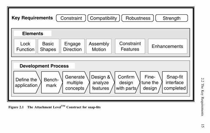
The complete ALC for snap-fits is shown in Fig. 2.1. The construct contains three major
groups: key requirements, elements and the development process. In this chapter, the key
requirements and the elements will be introduced and explained. For completeness, the snap-
fit development process is also shown although it is not discussed in detail until Chapter 7.
Key requirements are the common technical characteristics shared by all fundamentally
sound snap-fits and they describe the important relationships between the elements. We
know that specific application requirements (durability and ease of assembly, for example)
cannot be efficiently or consistently met unless the snap-fit key requirements are satisfied.
Because they are universal attachment requirements that must be satisfied, the key
requirements describe the domain within which the snap-fit elements and development
process exist.
Elements are either physical features of a snap-fit attachment or certain attributes used to
describe or characterize the snap-fit application. Constraint features (locks and locators) and
enhancements are physical elements of the attachment. The other elements are descriptive or
spatial. The elements are used at specific times during the development process to make
decisions about and to build the snap-fit interface.
A reminder: To make the terminology clear and to reinforce learning, find some products
that use snap-fits and refer to them as you read. Identify the key requirements and elements
as they are defined.
2.2 The Key Requirements
The key requirements are strength, constraint, compatibility, and robustness. They are a
snap-fit’s fundamental goals and they describe the desired relationships between the
elements, Fig. 2.2. Because they are goals, satisfying the key requirements is the criteria for
Key Requirements Constraint Compatibility StrengthRobustness
Elements
LockFunction
BasicShapes
EngageDirection
AssemblyMotion
ConstraintFeatures
Enhancements
Development Process
Snap-fitinterface
completed
Define theapplication
Bench-mark
Generatemultiple
concepts
Design &analyzefeatures
Confirmdesign
with parts
Fine-tune thedesign
Figure 2.1 The Attachment LevelTM Construct for snap-fits
2.2
Th
eK
eyR
equ
iremen
ts1
5

judging the success of a snap-fit design. Using the key requirements and the elements, we
will be able to describe the important attachment level design guidelines and rules. The
following sections explain each of the key requirements in detail.
2.2.1 Strength
Strength is the performance of lock features during assembly and the ability of both lock and
locator features to ensure attachment integrity for the life of the product. Attachment
integrity means maintaining part-to-part constraint without looseness, breakage or squeaks
and rattles. The product’s useful life includes initial handling and assembly, operation (of a
moveable snap-fit) and release and reassembly for maintenance or repair.
We should be familiar with strength because it is the basis for the traditional feature level
approach to snap-fit design. Analytical methods for determining proper geometry and
strengths of locators and locks are well documented. In Chapter 6, we discuss analytical
methods for evaluating strength and assembly performance of snap-fit features.
In a snap-fit, as with most attachments, retention strength is generally the most important
requirement. When we analyze snap-fit constraint features, we evaluate their performance
and design them to ensure they are indeed strong enough to survive assembly, carry loads
and resist forces. That is what we mean by feature strength. Strength, however is a
component of a more global design requirement called reliability.
Reliability is the attachment’s ability to hold parts together for the life of the product
without failure. Reliability requires feature strength but it also requires the attachment to be
properly assembled, used and serviced so that the designed-in strength is not lost. The
attachment can fail when this second group of requirements is not met, not because of
Key Requirements
Constraint Compatibility StrengthRobustness
The key requirements define thedomain of snap-fit technology at
the attachment level.
Figure 2.2 The snap-fit key requirements
16 Overview of the Attachment LevelTM Construct

inherent weakness, but because of improper assembly, use or service. So, the attachment
must be more than strong, it must be reliable. Reliability is ensured when adequate feature
strength is supplemented by the other three key requirements, Fig. 2.3.
Strength was described first because it is generally the ultimate goal of an attachment.
Strength, however, is a potential and it cannot be achieved reliably or cost effectively unless
the other three key requirements are met. The discussions of the remaining three key
requirements will explain how they affect attachment strength.
2.2.2 Constraint
Constraint is prevention or control of relative movement between parts. In a snap-fit, locator
and lock features provide constraint by transmitting forces across the interface and by
positioning the mating and base parts relative to each other, Fig. 2.4.
In Fig. 2.4, we also introduce two generic snap-fit applications that will be used
whenever possible to illustrate the concepts being discussed. They both represent relatively
common types of snap-fit applications. The first, Fig. 2.4a, is a solid attaching to a surface.
The second is a panel attaching to an opening, Fig. 2.4b. The terms solid, surface, panel and
opening are four of the basic shapes used to describe snap-fits. The concept of basic shapes
will be explained shortly.
All the key requirements are important to the attachment’s performance and reliability,
but constraint is the most fundamental requirement of a snap-fit. Success in the other three
key requirements depends on a properly constrained snap-fit. Because it describes feature
interactions, constraint is strongly tied to the idea of the snap-fit as a system.
Consider the mating part in a snap-fit as an object in space and the base part as ground.
A free object in space can move in any of 12 ways. Six are translational movements (þ or �)
along the three axes of a Cartesian coordinate system and six are rotational movements
(þ or �) around the axes, Fig. 2.5. We will call these six linear and six translational
movements Degrees of Motion or DOM. A totally unconstrained mating part can move in all
12 DOM relative to the base part. All 12 motions cannot occur simultaneously although
combinations of rotation or translation involving any three adjacent axes are possible. The
snap-fit’s purpose is to prevent or control (i.e. constrain) mating part movements relative to
the base part in all 12 DOM. Thus we can quantify constraint in terms of degrees of motion
(DOM).
Reliabilityand
durability=
Featurestrength +
Constraint
Compatibility
Robustness
Figure 2.3 Strength alone does not guarantee a good attachment
2.2 The Key Requirements 17

Figure 2.5 There are 12 possible directions or degrees of motion (DOM) for an object in space
Figure 2.4 Constraint features in an attachment provide mating part to base part positioningand resist external forces
18 Overview of the Attachment LevelTM Construct
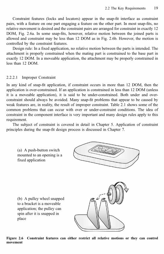
Constraint features (locks and locators) appear in the snap-fit interface as constraint
pairs, with a feature on one part engaging a feature on the other part. In most snap-fits, no
relative movement is desired and the constraint pairs are arranged for constraint in exactly 12
DOM, Fig. 2.6a. In some snap-fits, however, relative motion between the joined parts is
allowed and constraint may be less than 12 DOM as in Fig. 2.6b. However, the motion is
controlled by the constraint features.
Design rule: In a fixed application, no relative motion between the parts is intended. The
attachment is properly constrained when the mating part is constrained to the base part in
exactly 12 DOM. In a moveable application, the attachment may be properly constrained in
less than 12 DOM.
2.2.2.1 Improper Constraint
In any kind of snap-fit application, if constraint occurs in more than 12 DOM, then the
application is over-constrained. If an application is constrained in less than 12 DOM (unless
it is a moveable application), it is said to be under-constrained. Both under and over-
constraint should always be avoided. Many snap-fit problems that appear to be caused by
weak features are, in reality, the result of improper constraint. Table 2.1 shows some of the
common problems that can occur with over or under-constraint conditions. The idea of
constraint in the component interface is very important and many design rules apply to this
requirement.
The subject of constraint is covered in detail in Chapter 5. Application of constraint
principles during the snap-fit design process is discussed in Chapter 7.
Figure 2.6 Constraint features can either restrict all relative motions or they can controlmovement
2.2 The Key Requirements 19

2.2.3 Compatibility
Compatibility is harmony in the snap-fit interface between all the elements. It is the result of
selecting the assembly motion and engage direction and arranging the constraint features to
comprehend the components’ basic shapes and allow ease of assembly. Some combinations
of basic shapes, constraint features, assembly motions and engage directions are preferred;
others can result in difficult assembly and=or feature damage and should be avoided.
Incompatibility is often a subtle mistake, not easily recognized until symptoms and problems
occur in assembly. This is why improved spatial awareness and reasoning is important in
snap-fit development. We do not quantify compatibility as we do constraint; instead it is used
as a factor in qualitative judgments about attachment options. Two examples of poor
compatibility follow.
The first application shows assembly motion=constraint feature incompatibility, Fig. 2.7.
The mating part has a lug, an inflexible locator feature. The wall on the right side of the base
part restricts the available directions for the tip assembly motion required by presence of a
lug. The location of the lug means the operator must try to force the lug to deflect enough to
engage the hole in the base part. High assembly effort as well as broken parts are the most
likely result.
Table 2.1 Proper Constraint Versus Underconstraint and Overconstraint
Constraint condition
Effect on Proper Under Over
Noise Allows a close fitbetween parts
Part misalignment,possible looseness,squeaks and rattles
No direct effects
Assembly Features fit withoutinterference
No effects Difficult assembly dueto interferencebetween features
Cost Permits (cost-saving)normal or loosetolerances
No direct effects Requires close tolerances
Analysis Makes feature analysispossible
No effects Interface is staticallyindeterminate
Reliability Supports featurestrength for reliability
Improper lock loadingcan lead to lockfailure
Possible failure due toresidual strain betweenconstraint features
Possible componentdistortion undertemperature extremes
20 Overview of the Attachment LevelTM Construct

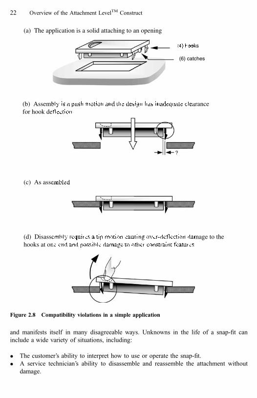
The second example shows two instances of compatibility violations, Fig. 2.8. During
assembly there is not enough clearance for the lock features to deflect. The result is higher
assembly effort and immediate damage to either the retention faces of the hooks or the edges
they engage. The second violation in this example is an assembly=disassembly motion
incompatibility. The assembly motion is a push, but the finger-pull feature forces the
disassembly motion to be a tip. This causes over-deflection damage to the hooks at the
finger-pull end of the panel and possible damage to the locator pins at both ends of the panel.
Important compatibility rules are:
� All physical features in the interface must be compatible with the assembly motion.
� The selected assembly motion must be compatible with the basic shapes.
� The assembly and disassembly motions should be the same (although opposite in
direction).
� Allow clearance for feature deflection during assembly and disassembly.
These are simple and seemingly obvious rules, yet they are violated. Both of the
examples of compatibility violations shown here are based on actual applications.
2.2.4 Robustness
Robustness is often defined as tolerance to dimensional variation; as a snap-fit requirement,
it has a broader meaning. We define snap-fit robustness as tolerance of the snap-fit to all the
variables and unknowns that exist in product design, manufacture, assembly and use.
Robustness is indeed tolerance to variation, but that variation is caused by many unknowns
(a) Solid to surface asassembled
(b) To assemble properly, the lug (2) mustengage before the corner (1) makes contact
1
2
Figure 2.7 Assembly motion=constraint feature incompatibility where the design forces thefeatures to engage out of order
2.2 The Key Requirements 21
and manifests itself in many disagreeable ways. Unknowns in the life of a snap-fit can
include a wide variety of situations, including:
� The customer’s ability to interpret how to use or operate the snap-fit.
� A service technician’s ability to disassemble and reassemble the attachment without
damage.
(a) The application is a solid attaching to an opening
(b) Assembly is a push motion and the design has inadequate clearancefor hook deflection
(c) As assembled
(d) Disassembly requires a tip motion causing over-deflection damage to thehooks at one end and possible damage to other constraint features
(4) hooks
(6) catches
Figure 2.8 Compatibility violations in a simple application
22 Overview of the Attachment LevelTM Construct

� The working environment and conditions in which the parts are assembled.
� The possibility of misuse, unexpected loads.
An example of the importance of robustness and its relation to strength in a snap-fit is
appropriate here. We will use a very simple application, represented in Fig. 2.9 by the basic
shapes panel and opening. This example is based on an actual design problem and we will
be referring to this particular application again in later chapters. For our purposes now, it is
sufficient to summarize the problem and solution very briefly.
The locking features in the original design are four cantilever hooks, one at each corner
of the mating part. The panel is a very low mass part and no external forces are applied to it
once it is in place. Each hook had been analyzed to ensure adequate strength for both
assembly and long-term retention of the panel to the opening. However, in spite of sufficient
strength in the hooks, some panels were falling off within the first few months of use.
Investigation of failed parts showed damage to one or more of the hooks. Some had taken a
permanent set while other hooks were broken off completely.
A first reaction to this problem might have been to simply strengthen the hooks; after all
they were breaking. This is a feature level fix and, as we will see, would have been a mistake.
A very important rule for understanding and fixing snap-fit problems is that feature level
problems cannot be fixed until we verify there are no attachment level problems in the snap-
fit. A study of the assembly process for this part revealed that:
� The application was in a vertical plane below the assembly operator’s natural line of
sight.
� It was a blind assembly, the operator’s hand would hide the attachment area as they held
the mating part (the panel) and tried to position it in the opening.
� The operator’s fingertips, as they grasped the panel in a normal manner, would contact
the area around the opening before the locks were properly positioned around the edge of
the opening, Fig. 2.10.
After observing the assembly operation, it was not too hard to conclude that the root
cause of the part problem was damage to the hooks during the assembly operation. Making
the hooks even stronger might have prevented damage but would have also increased the
assembly force, which could have caused ergonomic problems; and there were no guarantees
the problem would be solved. Other problems that could have also been occurring, which
stronger hooks would certainly not have solved, were the extra time it took the operator to
(4) hooksPush assembly motion
Figure 2.9 The application is a small panel attaching to a recessed opening
2.2 The Key Requirements 23

finesse the panel into place for assembly and the continuous frustration of carrying out a
difficult assembly.
What if the parts had been assembled in an automated operation, such as with a robot?
Higher assembly forces and frustration would no longer be an issue, but the required precise
positioning of the panel to the opening might have caused problems, even for an automated
operation.
One possible fix for this problem is shown in Fig. 2.11. With the addition of pins that
serve as both locators (constraint features) and as guides (an enhancement feature), the
application is now robust to the mechanics of the assembly process. The pins, first acting as
guides, engage the edge of the opening to orient and stabilize the mating part before the
operators’ fingers contact the base part. This ensures the hooks are in proper position for
engaging the edge and will not be damaged. The operator can easily position the panel in the
opening with the hooks resting against the edge and, with a final push, engage the hooks to
complete the assembly. Note that in this application, there was sufficient clearance for the
long pins proposed as a fix. However, other solutions were available if the clearance had
not been available. They will be discussed when we revisit this particular application in
Chapter 4.
This was a rather simple problem to identify; the real issue is why it happened in the first
place. Possibly the designer considered a panel to an opening as too basic and simple to
worry about. Thinking about the attachment as a system could have prevented operator
frustration, customer dissatisfaction, product warranty costs, engineering time spent to
change the design and tooling costs to modify the mold.
Pins added (4)
Figure 2.11 Possible fix to stabilize mating part and prevent hook damage during assembly
Figure 2.10 The operator’s fingertips interfere with proper hook alignment and engagement
24 Overview of the Attachment LevelTM Construct

Another important lesson to take away from this example: Never try to understand a
snap-fit problem without first watching it being assembled. If possible, perform the assembly
operation yourself to get a real feeling for what is happening.
To summarize, the hooks in this example had enough strength to survive normal
assembly deflections and to hold the panel in place once it was engaged. But, strength was
not enough. The entire system was not robust to the assembly process; therefore the
attachment was not reliable. In conclusion, robustness helps to ensure that feature strength is
properly utilized; this in turn ensures reliability of the snap-fit attachment.
As with compatibility, we do not quantify robustness. But it is an important goal and, as
such, it should influence many design decisions. The enhancements described in Chapter 4
address many robustness issues.
This completes the discussion of the four key requirements. Their relationship is shown
in Fig. 2.12. The ultimate goal is feature strength for attachment durability and reliability.
Proper constraint is the most fundamental of the requirements and is the basis for the other
three requirements. Robustness and compatibility depend on proper constraint to be effective
and also help to enable feature strength.
2.3 Elements of a Snap-Fit
Six elements make up the descriptive=spatial and physical description of a snap-fit
attachment. By learning them, you will be building an organized structure of snap-fit
technology in your mind. This is something like defining folders in a filing system. With this
‘‘filing system’’ you will find that remembering and using specific snap-fit features in design
solutions will be made easier.
The six elements are divided into two groups, Fig. 2.13. Four descriptive=spatial
elements are used to describe the application in specific attachment level terms that will help
us apply the development process. Two physical elements are used to describe the actual
features (or building blocks) of the attachment interface.
Constraint
Robustness Compatibility
FeatureStrength
Figure 2.12 The four key requirements
2.3 Elements of a Snap-Fit 25

Key Requirements Constraint Compatibility StrengthRobustness
Elements
LockFunction
BasicShapes
EngageDirection
AssemblyMotion
ConstraintFeatures
Enhancements
The spatial and descriptive elements of a snap-fit The physical elements of a snap-fit
Figure 2.13 The six elements of a snap-fit
26
Ov
erview
of
the
Attach
men
tL
evel T
MC
on
struct

2.3.1 Function
Function is the first of the descriptive elements. It is the attachment’s fundamental purpose,
what the locking features in the snap-fit must do. Function is not one of the more important
elements in terms of developing a snap-fit. However, it is useful in grouping lock features
with respect to various performance requirements, thus it contributes to an overall
understanding of the snap-fit technology. Function is described in terms of action,
attachment type, retention and lock type:
2.3.1.1 Action
Action is the potential for movement designed into the snap-fit application.
In fixed snap-fits, no relative motion between parts can occur after they are locked
together. The application is constrained in exactly 12 degrees of motion. The push-button
switch in Fig. 2.6a and the panel-to-opening examples in Figures 2.8 and 2.9 are also fixed
snap-fits.
In moveable snap-fits, relative motion can occur between the joined components when
they are engaged. The components are never completely separated during this motion. When
no constraint features limit this motion, it is free movement. The pulley shown in Fig. 2.6b is
an example. When locks or locators control or regulate the motion so the mating part is
sometimes immobile, it is controlled movement, Fig. 2.14.
Where free movement can occur, then no constraint exists in those directions and the
attachment will be (properly) constrained in less than 12 degrees of motion. The pulley is
properly constrained in 10 degrees of motion.
2.3.1.2 Attachment type
The snap-fit may be the final attachment or it may be temporary until some other attachment
occurs.
Mating part(panel) is hinged
to the opening
A (non-releasing) lockcontrols panel
movement
Figure 2.14 Controlled movement in a panel to opening
2.3 Elements of a Snap-Fit 27

The snap-fit is final when it is the attaching method that will hold the application
together throughout its useful life. Most snap-fits fall into this group and, in all the examples
shown thus far, the lock is intended to be the final attachment.
Temporary snap-fits hold the application only until some other attachment occurs. They
only need to be strong and effective enough to position the mating part to the base part until
the final attachment is made. Temporary snap-fits can support design for assembly by
allowing build-up of several parts prior to final attachment. They may sometimes save
money by allowing a less expensive final attaching process to be used, a slow-cure instead of
rapid-cure adhesive for example.
2.3.1.3 Retention
Retention refers to the nature of the locking pair: permanent or non-permanent.
Permanent locks are not intended for release, Fig. 2.15. No lock is truly permanent, but
these locks, once engaged, are difficult to separate. In some cases, they can be released with
tools or high effort, but damage to the lock or parts may result. They are indicated where
non-serviceable attachments are to be made or where evidence of product tampering is
required. They may also be useful where an attachment must survive sudden impact forces
that could cause a non-permanent lock to release. Figure 2.15a shows a trap lock where the
locking fingers are contained within the interface with no access for releasing them. Figure
(a) Permanent trap lock
Locking fingers (2)engage undercutsin wall
(b) Permanent hook lock
A wall behind the hook resistsrelease
Figure 2.15 Permanent locks
28 Overview of the Attachment LevelTM Construct

2.15b is a hook engaging a strap-like feature on a wall. Assembly forces are high, but once
engaged, the wall prevents hook end rotation for release.
Non-permanent locks are intended for release. Two kinds of non-permanent locks are
identified in the lock type classification.
2.3.1.4 Lock type
Refers to how the lock feature works to allow part separation, Fig. 2.16.
Releasing locks are designed to allow part separation when a predetermined separation
force is applied to the parts, Fig. 2.16a.
Non-releasing locks require manual lock deflection for part separation, Fig. 2.16b. A
non-releasing lock is also shown in Fig. 2.14. Note that non-releasing locks may release
under certain conditions. The non-release function is not a guarantee against unintended
separation.
2.3.1.5 Function Summary
Function describes exactly what the locking features must do in the application. As we will
see in Chapter 3, some lock features are better than others at performing some of these
functions. The function decision is summarized in Fig. 2.17. Describe an application by
starting at the top and working down through the four levels. Table 2.2 lists examples of the
various ways snap-fits are classified by function.
2.3.2 Basic Shapes
Basic shapes are the second descriptive element. They are simple geometric shapes that
describe the parts being attached. Classifying components by shape allows us to think of an
application in generic terms. This is important because it helps us transfer snap-fit concepts
between applications. Most importantly, however, use of basic shapes helps us to visualize
the attachment. This supports the spatial reasoning needed to develop good snap-fit
concepts.
(b) Non-releasing(a) Releasing
Figure 2.16 Non-permanent locks
2.3 Elements of a Snap-Fit 29

Action Fixed Moveableor
Purpose Temporary Finalor
Retention Permanent Non-permanentor
Release Non-releasing Releasingor
Figure 2.17 Lock function flowchart
Table 2.2 Function Examples
Application Action Purpose Retention Release
Switch assembly into anopening. Similar toFig. 2.6a.
Fixed Final Generallynon-permanentfor service
Releasing ifno access formanual release
The rocker switch in aswitch assembly.
Moveable(controlled)
Final Generallynon-permanentfor service
Releasing ornon-releasing
Battery access panel(slide to release) in a TVremote control unit.
Fixed Final Non-permanent Generally releasing
Battery access panel(tip to release) in a toy.Similar to Fig. 2.14.
Fixed Final Non-permanent Generallynon-releasing
Access cover for acircuit board requiringmanufacturer serviceonly.
Fixed Final Permanent N=A
Pulley to a bracket,Fig. 2.6b.
Moveable (free) Final Generallynon-permanentfor service
Releasing ornon-releasing
Lamp lens snapped tolens carrier prior toepoxy bonding.
Fixed Temporary N=A N=A

2.3.2.1 Mating Part and Base Part
We start describing basic shapes by defining the two components that make up a typical
snap-fit as the mating part and the base part.
The base part may be large and obviously stationary or fixed. The mating part is typically
smaller than the base part, held in the hand(s) and moved into attachment with the larger,
stationary base part. The push button switch and the pulley in Fig. 2.6, the generic solids in
Figures 2.7 and 2.8, and the small panel in Fig. 2.9 are all considered mating parts. The
mating part will generally be one of the three basic shapes: solid, panel or enclosure. The
base part will generally be a solid, surface, opening or cavity, Table 2.3.
We can usually identify the mating and base parts by using the size and movement
criteria described above. We can also use the basic shape for identification. If all these fail to
distinguish the mating from the base part, then the parts are probably so similar that an
arbitrary selection can be made. Note that these distinctions are true most of the time, some
exceptions will be shown later in this section. Exceptions do occur, but that does not reduce
the value of having these definitions.
2.3.2.2 Basic Shape Descriptions
� Solid—Components with both rigidity and depth, Fig. 2.18. Solids may have constraint
features in three dimensions.
� Panels—Relatively thin components, they tend to be compliant in bending and torsion,
Fig. 2.19. Constraint features are generally at or near the perimeter but can be anywhere
on the panel.
Figure 2.18 Solids
Table 2.3 Basic Shapes Summary
Basic Shapes
Part Solid Panel Enclosure Surface Opening Cavity
Mating part Common Common Common Rare Rare LowBase part Common Rare Rare Common Common Common
2.3 Elements of a Snap-Fit 31
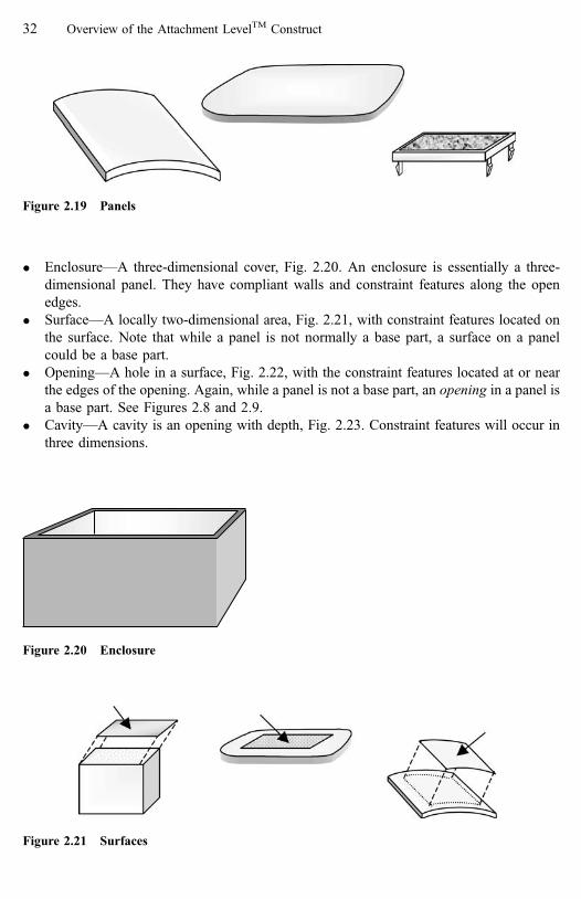
� Enclosure—A three-dimensional cover, Fig. 2.20. An enclosure is essentially a three-
dimensional panel. They have compliant walls and constraint features along the open
edges.
� Surface—A locally two-dimensional area, Fig. 2.21, with constraint features located on
the surface. Note that while a panel is not normally a base part, a surface on a panel
could be a base part.
� Opening—A hole in a surface, Fig. 2.22, with the constraint features located at or near
the edges of the opening. Again, while a panel is not a base part, an opening in a panel is
a base part. See Figures 2.8 and 2.9.
� Cavity—A cavity is an opening with depth, Fig. 2.23. Constraint features will occur in
three dimensions.
Figure 2.20 Enclosure
Figure 2.19 Panels
Figure 2.21 Surfaces
32 Overview of the Attachment LevelTM Construct
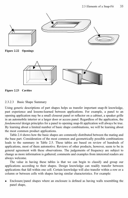
2.3.2.3 Basic Shape Summary
Using generic descriptions of part shapes helps us transfer important snap-fit knowledge,
past experience and lessons-learned between applications. For example, a panel to an
opening application may be a small closeout panel or reflector on a cabinet, a speaker grille
in an automobile interior or a larger door or access panel. Regardless of the application, the
fundamental design principles for a panel to opening snap-fit application will always be true.
By learning about a limited number of basic shape combinations, we will be learning about
the most common product applications.
Table 2.4 shows how the basic shapes are commonly distributed between the mating and
the base part. Consideration of the most common and geometrically possible combinations
leads to the summary in Table 2.5. These tables are based on review of hundreds of
applications, most of them automotive. Reviews of other products, however, seem to be in
general agreement with these observations. The judgements of frequency are subject to
change as more information is gathered; comments and examples from interested readers are
always welcome.
The value in having these tables is that we can begin to classify and group our
applications according to their shapes. Design knowledge can readily transfer between
applications that fall within one cell. Certain knowledge will also transfer within a row or a
column or between cells with shapes having similar characteristics. For example:
� Enclosure=panel shapes where an enclosure is defined as having walls resembling the
panel shape,
Figure 2.23 Cavities
Figure 2.22 Openings
2.3 Elements of a Snap-Fit 33

Table 2.4 Observed Frequencies of Basic Shape Combinations
Base part shapes
Mating part shapes SOLid
(common)
PANel
(rare)
ENClosure
(rare)
SURface
(common)
Opening
(common)
CAVity
(common)
SOLid(common)
SOL-SOLhigh
C SOL-ENCLow
SOL-SURhigh
SOL-OPhigh
SOL-CAVhigh
PANel(common)
PAN-SOLlow
PAN-PANlow
PAN-ENCLow
PAN-SURlow
PAN-OPhigh
PAN-CAVlow
ENClosure(common)
ENC-SOLlow
C ENC-ENCLow
ENC-SURhigh
ENC-OPlow
ENC-CAVlow
SURface(rare)
SUR-SOLlow
C SUR-ENCLow
C X X
Opening(rare)
X X X X X X
CAVity(low)
X X X X X X
High—A very common basic shape combination.
Low—Less frequently observed.
C—Covered by some other combination. (Subject to change).
X—Judged to be geometrically impossible. (Subject to change).
Table 2.5 Most Common Basic Shape Combinations; the High Usage Area of Table 2.4
Base part shapes
Mating part shapes SOLid
(common)
ENClosure
(rare)
SURface
(common)
Opening
(common)
CAVity
(common)
SOLid(common)
SOL-SOLhigh
SOL-ENClow
SOL-SURhigh
SOL-OPhigh
SOL-CAVhigh
PANel(common)
PAN-SOLlow
PAN-ENClow
PAN-SURlow
PAN-OPhigh
PAN-CAVlow
ENClosure(common)
ENC-SOLlow
ENC-ENClow
ENC-SURhigh
ENC-OPlow
ENC-CAVlow
High—A very common basic shape combination.
Low—Less frequently observed.
34 Overview of the Attachment LevelTM Construct

� Opening=cavity shapes where the cavity can be thought of as an opening with depth.
� Surface=panel shapes when the surface is located on a panel.
Certain basic shape combinations have good and bad characteristics. Some basic shape
combinations should be avoided. Each combination can have certain preferred assembly
motions, constraint features and enhancements that help ensure a good snap-fit. Once these
other elements of a snap-fit are discussed, we will be able to summarize some desirable and
undesirable characteristics for the common basic shape combinations.
The combinations in Table 2.5 are the most common. Some exceptions to the general
rules are shown in Fig. 2.24. A badge or a covering trim application would be a panel to a
surface, Fig. 2.24a. A computer diskette cover assembly, Fig. 2.24b, is a panel to panel
application, although we can also think of it as surface to surface. We can also imagine an
enclosure to enclosure application, Fig. 2.24c, and a panel to a cavity, Fig. 2.24d.
2.3.3 Engage Direction
Engage direction is the third descriptive element. It is the final direction the mating part
moves as it locks to the base part and is described by a directional vector (of zero magnitude)
defining the mating part’s movement as locking occurs, Fig. 2.25a. Note that there may be
movements of the mating part in space prior to the final engaging motion, the direction(s) of
those movements is not considered engage direction. As we select an engage direction, we
are also, by default, selecting a separation direction; it is the relationship of the separation
(a) Trim to a surface (b) Panel to panel
(c) Enclosure to enclosure (d) Panel to cavity
Figure 2.24 Less common basic shape combinations
2.3 Elements of a Snap-Fit 35

direction and the locking features we are most concerned about, Fig. 2.25b. The locking
features (lock pairs) will be required to resist any forces on the attachment that tend to
separate the parts and, generally, the locking feature(s) is the weak link in the attachment
system. An important rule when identifying allowable engage directions is:
Select an engage direction so that the (opposite) separation direction is not in the samedirection as any significant forces on the attachment.
This simple rule means that there should be no significant transient or long-term forces
trying to release the lock and separate the parts. In Fig. 2.26a we see a solid to opening
application having two available engage directions. The preferred engage direction is in the
–Y direction so that the separation direction is opposite the force on the mating part. This
allows the force to be carried by the surface of the flange (a locating area) on the solid rather
than by any locking features.
What is a significant transient force; what is a significant long-term force? That is up to
the designer to determine with the help of a polymers expert. The answer will depend on the
magnitude of the force, the force history and the long and short-term performance
(a) Engagement is in the -Y direction
X
Y
Z
(b) The lock features engage in the -Y direction and separate in the +Y direction.
-Y
+Y
Figure 2.25 Engage direction
36 Overview of the Attachment LevelTM Construct
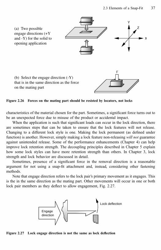
characteristics of the material chosen for the part. Sometimes, a significant force turns out to
be an unexpected force due to misuse of the product or accidental impact.
When the application is such that significant loads can occur in the lock direction, there
are sometimes steps that can be taken to ensure that the lock features will not release.
Changing to a different lock style is one. Making the lock permanent (as defined under
function) is another. However, simply making a lock feature non-releasing will not guarantee
against unintended release. Some of the performance enhancements (Chapter 4) can help
improve lock retention strength. The decoupling principles described in Chapter 5 explain
how some lock styles can have more retention strength than others. In Chapter 3, lock
strength and lock behavior are discussed in detail.
Sometimes, presence of a significant force in the removal direction is a reasonable
argument for not using a snap-fit attachment and, instead, considering other fastening
methods.
Note that engage direction refers to the lock pair’s primary movement as it engages. This
is the in the same direction as the mating part. Other movements will occur in one or both
lock pair members as they deflect to allow engagement, Fig. 2.27.
Lock deflection
Engagedirection
Figure 2.27 Lock engage direction is not the same as lock deflection
(a) Two possibleengage directions (+Yand -Y) for the solid toopening application
(b) Select the engage direction (-Y)that is in the same direction as the forceon the mating part
Figure 2.26 Forces on the mating part should be resisted by locators, not locks
2.3 Elements of a Snap-Fit 37

While there may be a number of possible engage directions, the truly feasible engage
directions for any particular application are limited. In addition to the limitations imposed by
external forces, other limitations can be interactions between the parts’ basic shapes,
ergonomics, packaging and access conditions.
2.3.4 Assembly Motion
Assembly motion is the fourth and last descriptive element. It is defined by the generic
motions: push, slide, tip, twist and pivot. Think of assembly motion as what a human
operator must do to assemble the components. It is the final motion of the mating part as it
locks to the base part, Fig. 2.28. Assembly motion helps the designer visualize the mating-
part to base-part assembly process. Like basic shapes, assembly motions support generic
snap-fit descriptions and spatial reasoning for snap-fit concept development. They may also
have ergonomic implications in some applications where an awkward position and excessive
assembly force, when combined with a certain assembly motion, can result in increased
likelihood of repetitive motion injury. As we will learn, they also have significant impact on
the attachment design with respect to strength.
� Push—A linear movement where contact between the mating and base parts occurs
(relatively) shortly before final locking, Fig. 2.28a. Some guide feature contact may
occur before the locators or locks engage.
� Slide—A linear movement with early contact between locator pairs followed by
additional mating part movement with continuous contact with the base part prior to final
locking, Fig. 2.28b. Both push and slide are simple motions. The next three are more
complex.
� Tip—A rotational movement. A locating feature(s) on the mating part, (1) in Fig. 2.28c,
is first engaged to the base part. Initial engagement is followed by mating part rotation
(2) around the initial locator pair until locking feature engagement occurs.
� Twist—A rotational movement. A mating part with axisymmetric constraint features is
first engaged to the base part with a linear motion, (1) in Fig. 2.28d. The mating part
is rotated (2) around the axis so its constraint features engage a complementary
arrangement of constraint features on the base part. The behavior is similar to that of a
‘‘quarter-turn’’ fastener.
� Pivot—A rotational movement. The mating part is first engaged to the base part at one
locator pair with a push motion, (1) in Fig. 2.28e. The mating part is pivoted around that
point with continuous contact until lock engagement occurs (2). A pivot can be thought
of as a combination of both the tip and slide motions, with rotation about one locator pair
and continuous contact occurring simultaneously.
Note how some assembly motions may be preferable to others depending on the basic
shapes involved, application accessibility and operator ergonomics. Table 2.6 shows some of
these possibilities and provides an indication of the more preferred motions. We will also see
how assembly motion contributes to creativity during the development process (Chapter 7)
and, like basic shapes, helps organize thinking about applications.
38 Overview of the Attachment LevelTM Construct

(a) Push-panel to opening and solid to cavity
(b) Slide-solid to surface
(e) Pivot-solid to surface
1
2
(d) Twist-solid to cavity
1
2
(c) Tip-solid to opening
1
2
Figure 2.28 Assembly motions
2.3 Elements of a Snap-Fit 39

We are finished introducing the four descriptive elements of snap-fit design: function,
basic shape, engage direction and assembly motion. They will be applied during the
development process described in Chapter 7. We now move on to the physical elements.
These are the actual ‘‘building blocks’’ of the snap-fit. Unlike the preceding detailed
discussion of the descriptive=spatial elements, we will only provide a brief introduction to
the physical elements here because they are discussed in great detail in the next two
chapters.
2.3.5 Constraint Features
We have already explained that constraint involves controlling mating part movement
relative to the base part. Constraint features are the mechanisms that provide constraint in the
attachment. There are two kinds of constraint feature: locator features and lock features.
Usually, the names are shortened to just locators and locks.
Locators and locks are the ‘‘necessary and sufficient’’ features for a snap-fit attachment.
In other words, they are all that is needed to create a snap-fit. Both types of features can be
found on either the mating or base part. As discussed in the section on key requirements,
proper constraint as provided by locators and locks is the basis for a successful snap-fit.
2.3.5.1 Locator Features
Locator features (locators) are relatively inflexible constraint features, Fig. 2.29. They
provide strength against forces across the interface and they provide precise positioning of
the mating part to the base part. A good term that describes what locating features do is
nesting. Think of locators as the interface features that cause the parts to nest together.
Table 2.6 Common Basic Shape Combinations and Available Assembly Motions
Base part shapes
Mating part shapes Solid Enclosure Surface Opening Cavity
Solid Push PushSlide Slide Push SlideTip N=A Tip Tip Tip*Twist Twist Twist* TwistPivot Pivot
Push Push PushPanel N=A N=A Slide Tip Tip
Tip
Enclosure Slide Push PushTip Tip Tip Tip N=ATwist* Twist* Twist*
* Some availability, depending on specific part geometry. Twist is generally not preferred for large parts.
40 Overview of the Attachment LevelTM Construct

Locators may be distinct features added to the attachment strictly to provide locating,
Fig. 2.29a, or they may be natural locators: pre-existing features on the mating or base part
such as a wall, surface or edge that perform a locating function, Fig. 2.29b.
In fixed applications, locators prevent motion and carry loads in all but the mating part
removal direction. In moveable applications, they may also be used to control or limit
motion in the direction(s) of movement (controlled action).
Locator features are grouped into common types: pin, cone, track, wedge, catch, surface,
edge, lug, land, slot and hole. We also classify the living hinge as a locator. The features are
grouped in this manner because each type has a unique set of constraint behaviors.
Presence of a locator on one component implies a mating locator on the other.
Together they make up a locator pair, Fig. 2.30. When we discuss locators in a snap-fit,
remember that we are really referring to a locator pair. Locators are discussed in detail in
Chapter 3.
2.3.5.2 Lock Features
Lock features, or simply locks, are constraint features which hold parts in the located or
nested condition. With certain notable exceptions (discussed in Chapter 3), they are weak
compared to locators because locks must deflect to allow assembly. Once the mating and
base parts are located the locking features hold them in that position, Fig. 2.31, so the strong
locators can do their job of providing positioning and carrying forces across the interface.
(a) Lugs and lands are distinct locator features
Lands Lugs
(b) Natural locator features
SurfaceEdges
Figure 2.29 Locator constraint features
2.3 Elements of a Snap-Fit 41

Integral locks are grouped into common types: hook, catch, annular, torsional and trap.
They are defined in a particular application by specific functional characteristics. These
characteristics were introduced when we defined the descriptive element function.
Because locks deflect elastically to allow assembly, they must be flexible (weak) in that
direction. After deflecting for assembly, they return toward their initial position. This results
in interference between the lock and the other half of the lock pair (located on the other
part). As long as this interference is maintained, the parts are locked together. Because locks
prevent mating part movement away from the base part, (the separation direction) they must
have some strength in that direction, Fig. 2.32.
Presence of a lock on one component implies a mating feature on the other. Generally,
the mating feature to the lock is a locator, not another lock, because the lock should engage a
strong and inflexible feature. Together the lock and locator make up a lock pair, Fig. 2.33.
As with locator pairs, when we discuss locking in a snap-fit, we always assume a lock pair
exists. Locks are discussed in detail in Chapter 3.
Locks
Locks
Figure 2.31 Once the parts are located, locks hold them in place
Lugs toedge Catches to edge
Surface tosurface
Figure 2.30 Locator pairs
42 Overview of the Attachment LevelTM Construct
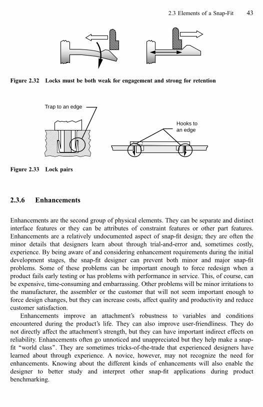
2.3.6 Enhancements
Enhancements are the second group of physical elements. They can be separate and distinct
interface features or they can be attributes of constraint features or other part features.
Enhancements are a relatively undocumented aspect of snap-fit design; they are often the
minor details that designers learn about through trial-and-error and, sometimes costly,
experience. By being aware of and considering enhancement requirements during the initial
development stages, the snap-fit designer can prevent both minor and major snap-fit
problems. Some of these problems can be important enough to force redesign when a
product fails early testing or has problems with performance in service. This, of course, can
be expensive, time-consuming and embarrassing. Other problems will be minor irritations to
the manufacturer, the assembler or the customer that will not seem important enough to
force design changes, but they can increase costs, affect quality and productivity and reduce
customer satisfaction.
Enhancements improve an attachment’s robustness to variables and conditions
encountered during the product’s life. They can also improve user-friendliness. They do
not directly affect the attachment’s strength, but they can have important indirect effects on
reliability. Enhancements often go unnoticed and unappreciated but they help make a snap-
fit ‘‘world class’’. They are sometimes tricks-of-the-trade that experienced designers have
learned about through experience. A novice, however, may not recognize the need for
enhancements. Knowing about the different kinds of enhancements will also enable the
designer to better study and interpret other snap-fit applications during product
benchmarking.
Trap to an edge
Hooks toan edge
Figure 2.33 Lock pairs
Figure 2.32 Locks must be both weak for engagement and strong for retention
2.3 Elements of a Snap-Fit 43

Enhancements are classified into four major groups: assembly, activation, performance
and manufacturing. Enhancements are described in detail in Chapter 4; here we will briefly
introduce them:
Enhancements for Assembly—Features or attributes that support product assembly:
� Guidance—Ensures smooth engagement and latching of mating parts. Guidance
enhancements are further broken down into guides, clearance and pilots.
� Operator feedback—Attributes and features ensuring clear and consistent feedback that
the attachment has been properly made.
Activation enhancements—Informational and mechanical enablers that support attach-
ment disassembly or usage:
� Visuals—Provide information about attachment operation or disassembly.
� Assists—Provide a means for manual deflection of non-releasing locks.
� User feel—Attributes and features that ensure a good feel in a moveable snap-fit.
Performance enhancements—Ensure that the snap-fit attachment performs as expected:
� Guards—Protect sensitive lock features from damage.
� Retainers—Provide local strength and improve lock performance.
� Compliance—Attributes and features that take up tolerance and help maintain a close fit
between mating parts without violating constraint requirements.
� Back-up lock—Provides a back-up means of attachment.
Manufacturing enhancements—Techniques that support part and mold development,
manufacturing and part consistency.
Many manufacturing enhancements are documented in standard design and manufactur-
ing practices for injection-molded parts and are already recognized as important factors in
plastic part design. They fit neatly into the ALC as enhancements and, because of their
importance, are included.
� Process-friendly design—Following recommended and preferred plastic part design
practices.
� Fine-tuning—Practices that allow for easy mold adjustments and part changes or fine-
tuning.
Enhancements are summarized in Table 2.7 and are discussed in detail in Chapter 4.
2.3.7 Elements Summary
This concludes the elements of snap-fit design. Four of the elements are spatial or
descriptive: lock function, basic shape, engage direction and assembly motion. Two elements
are physical parts of the snap-fit: constraint features (consisting of locators and locks) and
enhancements. The purpose of Chapter 2 has been to provide a detailed discussion of the
spatial=descriptive elements and an overview of the physical elements. The physical
elements require much more detailed explanation and are covered in Chapters 3 and 4. All of
the elements will be applied during the snap-fit development process described in Chapter 7.
44 Overview of the Attachment LevelTM Construct

2.4 Summary
The key requirements and elements of the Attachment LevelTM Construct for snap-fits, Fig.
2.1, were described in Chapter 2. To support the human mind’s desire for organization, snap-
fit design technology has been described in terms of key requirements and elements. Key
requirements are the common and fundamental goals of all good snap-fit attachments.
Elements are the spatial=descriptive and physical parts of the domain that we use to make
decisions about the snap-fit and construct the attachment concept. Using the key
Table 2.7 Enhancements Summary
Why What
For assembly
Guidance Ease of assembly Guide—stabilize partsClearance—no interferencePilot—correct orientation
Feedback Indicate good assembly Tactile, audible or visual
For activation
Visuals Indicate disassembly,assembly and operation
Words, arrows, symbols
Assists Enable disassembly,assembly and operation
Extensions for fingersor tools
User feel Perceived quality Force-time signature
For strength and performance
Guards Protect weak or sensitive Prevent over-deflectionfeatures Reduce strain
Increase retention strengthRetainers Strengthen locks Stiffen the lock area
Support the lock
Compliance Take up tolerances and Elastic featuresprevent noise Local yield
Back-up lock A back-up attaching system Available fastenersAdaptable interfaces
For manufacturing
Process-friendly Consistent features Simple designs
Minimum cycle times Follow mold and productdesign guidelines
Fine-tuning Speeds development Local adjustments
Easy part fine-tuning and Metal-safe designsadjustments for quality Adjustable inserts
2.4 Summary 45

requirements and elements, we can also develop attachment level design guidelines and
rules.
Some of the elements are generic, allowing the snap-fit designer to think in terms of
simple shapes and motions. This supports the spatial understanding and reasoning that is so
important to successful snap-fit design. It also enables transfer of useful snap-fit knowledge
between applications. Specific meanings for snap-fit terms also allow clear, unambiguous
communication between designers about snap-fits.
2.4.1 Important Points in Chapter 2
� The ALC defines and organizes the design space for snap-fits, explaining it in terms of
key requirements, elements and a development process.
� Every snap-fit should satisfy the four key requirements: constraint, compatibility,
robustness and strength.
� Feature strength for attachment reliability is the ultimate goal of most snap-fits and is one
of the key requirements. To have reliable strength, a snap-fit must satisfy the other three
key requirements.
� Constraint is the most fundamental of the key requirements. Proper constraint is required
for success in the other requirements.
� Many snap-fit problems can be traced to improper constraint.
� While constraint features are necessary and sufficient for a snap-fit attachment,
enhancements are required to make the attachment robust and ‘‘world-class’’.
� Use generic descriptions of part shapes to transfer important snap-fit knowledge, past
experience and lessons-learned between applications. Regardless of the application, the
fundamental design principles for a specific basic shape combination will always be true.
2.4.2 Important Design Rules Introduced in Chapter 2
� In a fixed application, no relative motion between the parts is intended. The attachment is
properly constrained when the mating part is constrained to the base part in exactly 12
DOM. In a moveable application, the attachment may be properly constrained in less
than 12 DOM.
� An important rule for understanding and fixing snap-fit problems is that feature level
problems cannot be fixed until one verifies there are no attachment level problems in the
snap-fit.
� Select a mating part to base part engage direction so that the (opposite) separation
direction is not in the same direction as any significant forces on the attachment.
� To ensure compatibility:
All physical features in the interface must be compatible with the assembly motion.
The selected assembly motion must be compatible with the basic shapes.
The assembly and disassembly motions should be the same (although opposite in
direction.
Clearance must be provided for feature movements during assembly and disassembly.
46 Overview of the Attachment LevelTM Construct

3 Constraint Features
Constraint features are the locking and locating features that actually hold the parts together.
3.1 Introduction
Constraint is the most fundamental of the key requirements for a snap-fit and the features
that provide positioning and strength in the attachment are the most important parts of a
snap-fit. Many of the attachment level design rules that will be discussed in this and in later
chapters involve getting proper constraint.
Recall the definition of a snap-fit from Chapter 1:
A snap-fit is a mechanical joining system in which attachment occurs using locating and locking
features (constraint features) that are homogenous with one or the other of the parent components
being joined. Joining requires a flexible locking feature to move aside for engagement with the
mating part followed by return of the locking feature toward its original position to accomplish the
interference required to latch the components together. Locators, the second type of constraint
feature, are inflexible, providing strength and stability in the attachment. Enhancements complete
the snap-fit system, adding robustness and user-friendliness to the attachment.
Constraint features fall into two major groups: locators and locks. They were introduced
in Chapter 2 and described briefly. This chapter will describe the details of constraint
features and the concepts behind their use. Analysis of lock constraint features is discussed
in Chapter 6.
In most of the illustrations in this book, radii at corners are not shown because of the
complexity they add to the graphics creation process. However, the reader must keep in mind
that a basic rule of plastic part design is to avoid sharp corners. This rule applies to both
interior and exterior corners and to all features, including snap-fit features. Radii must be
specified where the feature meets the parent material as well as at all the angles within the
feature itself. The radius provides benefits to melt-flow for manufacturing, improves the
resulting part quality and reduces stress-concentrations effects in loaded areas.
3.2 Locator Features
Discussion of constraint features begins with locators for two reasons: Locators are the first
constraint features considered when we begin developing the snap-fit interface; second, they

are relatively simple features compared to the considerably more complex and varied lock
features locks.
By definition, locators are strong features. They provide part-to-part positioning
(locating) and should also carry all significant forces in the attachment. During snap-fit
development, locators are added to the interface in two ways. They are identified as pre-
existing part features, like edges and surfaces, that can serve a locating function. These are
called natural locators. Locators are also distinct features added to the interface specifically
to do the locating function. Each has advantages. Natural locators are in the part already and
do not add cost. Unlike distinct locator features, however, they are limited in constraint
capability and do not, as a rule, provide for easy dimensional control or fine-tuning.
3.2.1 Locator Styles
Locators, being strong and inflexible, normally have no assembly deflection issues
associated with them. Thus, unlike locks, they are relatively easy to understand and use.
With few exceptions locators, if they are analyzed at all, usually require only a simple
analysis of behavior under shear or compression loading. One notable exception is when a
locator is used as a low-deflection lock feature. This is discussed in the lock features section.
The following definitions may seem unnecessary at first. Individual locators are
identified in this manner in order to define them by name and characteristic shape. Locators
that seem similar can have important performance differences. These will become apparent
when one locator is paired with another in a locator pair. They will exhibit differences in
degrees of motion removed, tolerance to dimensional variation and assembly motions
allowed.
While there are infinite varieties of locators, we can organize most of them into three
logical groups: protrusion-like, surface-like and void-like. In addition, because of the role
they play when present in a snap-fit interface, living hinges are considered locators.
The first group consists of locators formed as a protrusion from a part, Fig. 3.1. Because
they are protrusions, these locators are generally not natural locators.
3.2.1.1 Lug
Lugs are protruding locator features characterized by an ‘‘L’’ section intended to engage over
an edge, Fig. 3.1a. Lugs are one of the most common locators and there are numerous
variations on the basic ‘‘L’’ shape. One useful modification of the common lug is a track. A
track is formed when two lugs face toward or away from each other and are extended to
create a strong locator that allows for a slide assembly motion.
3.2.1.2 Tab
Tabs are flat protrusions with parallel or slightly tapered sides, Fig. 3.1b. They normally
engage an edge or a slot.
48 Constraint Features [Refs. on p. 94]

3.2.1.3 Wedge
Wedges are a variation of the tab in which the base is much greater in area than a section
towards the end, Fig. 3.1c. The greater thickness at the base makes them potentially much
stronger than a tab. Wedges are intended to engage a slot and, like a cone, they provide
constraint along the axis of the taper as well as in lateral directions. Wedges, by definition,
have a base with a long and short axis.
3.2.1.4 Cone
Cones are a variation of the pin locator in which a section at the base is significantly larger
than a section towards the end of the feature, Fig. 3.1d. Cones engage holes and, like the
(a) Lug and track (b) Tabs
(e) Pins
(c) Wedges
(f) Catches
(d) Cones
Figure 3.1 Protrusions as locators
3.2 Locator Features 49

wedge, are intended to provide locating in the axial direction as well as in lateral directions.
Cones may have a round or a square section. The square section cones look like wedges, but
they are not. As a rule, because performance is identical and cones with a round section tend
to be more robust for dimensional performance as well as easier to create in the mold, the
round section cones are preferred over the square section cones.
Note that any features with thick sections, like cones and wedges, have important
limitations as to where they can be placed on an injection molded part. Good mold design
practice requires that thick sections be cored out, so appearance of the opposite surface and
accessibility can limit use of these features.
3.2.1.5 Pin
Pins are features having either constant section or slight taper along the axis of symmetry,
Fig. 3.1e. They may have round, square or complex sections. Pins generally engage holes,
slots or edges and constrain only in lateral directions. Note that, in injection molded parts,
features like pins can only have a truly constant section if they are formed in a plane parallel
to the split line of the mold. Otherwise, draft angle requirements will mean that a slight taper
exists.
3.2.1.6 Catch
Catches are wedge-shaped features, Fig. 3.1f. However, unlike the wedge feature, they are
intended to engage against an edge, not into a hole or slot.
Let us summarize protrusion type locators by noting their roots in one fundamental
feature. As shown in Fig. 3.2, all protruding locators are simply variations of a pin. Note
again that none of the protruding locators are natural locators. In other words, they are added
to the part specifically to perform the locating function. Some of the surface-like locators,
discussed next and shown in Fig. 3.3, can be natural locators.
3.2.1.7 Surface
Surfaces are locally flat or smooth areas, Fig. 3.3a. They constrain in only one direction and
are almost always natural locators.
3.2.1.8 Land
A land is a raised area on a surface, Fig. 3.3b. The land also provides a locating surface, but
it allows local dimensional control and a fine-tuning capability that the (natural locator)
surface may not be able to provide, at least not economically. Lands also permit clearance in
some applications for ease of assembly, find more on that topic in the chapter about
enhancements.
50 Constraint Features [Refs. on p. 94]

3.2.1.9 Edge
Edges are relatively thin areas; they are usually linear and orthogonal to a surface, Fig. 3.3c.
An edge is generally on a part wall or on a rib or gusset and it can be either a natural or
distinct locator, depending on the situation. Edges lend themselves quite readily to local
dimensional control and fine-tuning.
Similarly to the protrusion locators and the basic pin, we can show how the surface-like
locators can be evolved from a basic edge, Fig. 3.4.
The last group of locators is created by forming a void in a part, usually in a wall.
Whereas the surface-like locators may be added or natural locators; voids, like protrusions,
are almost always added specifically to perform a locating function.
Pin
Tab bent at a right angleis a lug
Pin stretchedsideways is a tab
Pin widened at thebase is a cone
Cone with a rectangularsection is a wedge
An asymmetric wedgeis a catch
Figure 3.2 The pin is the basis for all protrusion locators
3.2 Locator Features 51

3.2.1.10 Hole
Holes are openings in a panel or a surface. They may be round, square or some other shape,
Fig. 3.5a. Holes, by definition, constrain in at least four degrees of motion. They may
constrain in five DOM depending on the mating locator.
3.2.1.11 Slot
A slot is a hole elongated along one axis, Fig. 3.5b. The elongation serves to remove contact
(constraint capability) along the long axis of the slot. By definition, a slot constrains in at
least two and possibly three degrees of motion. Sometimes, the difference between a hole
and slot is determined only by the nature of the mating locator. This is explained in the
discussion of locator pairs.
3.2.1.12 Cutout
Cutouts are a hybrid of the hole and edge locators. A cutout has three active or useful edges
rather than one, Fig. 3.5c. Like a hole, the cutout provides additional constraint capability;
like an edge, it provides more assembly options. A cutout may look somewhat like a hole or
a slot. Once again, the classification depends on how it is used.
(a) Surfaces
(b) Lands
(c) Edges
Figure 3.3 Surface-like locators
52 Constraint Features [Refs. on p. 94]

(a) Holes
(b) Slots
(c) Cutouts
Figure 3.5 Voids as locators
An edge made wider isa surface
A controlled surface isa land
Edge
Figure 3.4 Edge as the basis for surface-like locators
3.2 Locator Features 53

Figure 3.6 shows how the void-like locators also derive from the edge. Holes and slots
are really an edge closed around on itself. Cutouts may be a fully closed edge or a three-
sided edge configuration.
3.2.1.13 Living Hinge
A living hinge is a relatively thin connective section between two parts, Fig. 3.7. It joins the
parts but also allows for (rotational) movement of one part relative to the other. In this sense
it behaves like a locator pair in a moveable application. Because living hinges act as the first
engaged locator pair and provide positioning as well as strength, they are classified as a
locator rather than a lock.
Figure 3.7 In a snap-fit, living hinges act as locators
An edge connected end toend is a hole
An elongatedhole is a slot
An edgecut into
a wall isa cutout
Edge
Figure 3.6 Edge as the basis for void-like locators
54 Constraint Features [Refs. on p. 94]
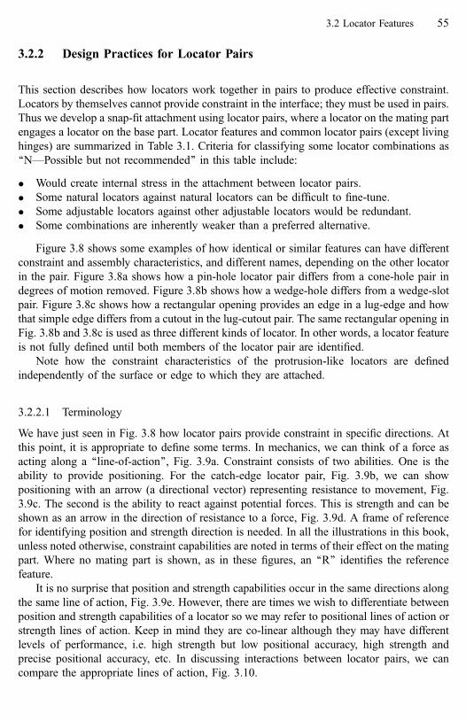
3.2.2 Design Practices for Locator Pairs
This section describes how locators work together in pairs to produce effective constraint.
Locators by themselves cannot provide constraint in the interface; they must be used in pairs.
Thus we develop a snap-fit attachment using locator pairs, where a locator on the mating part
engages a locator on the base part. Locator features and common locator pairs (except living
hinges) are summarized in Table 3.1. Criteria for classifying some locator combinations as
‘‘N—Possible but not recommended’’ in this table include:
� Would create internal stress in the attachment between locator pairs.
� Some natural locators against natural locators can be difficult to fine-tune.
� Some adjustable locators against other adjustable locators would be redundant.
� Some combinations are inherently weaker than a preferred alternative.
Figure 3.8 shows some examples of how identical or similar features can have different
constraint and assembly characteristics, and different names, depending on the other locator
in the pair. Figure 3.8a shows how a pin-hole locator pair differs from a cone-hole pair in
degrees of motion removed. Figure 3.8b shows how a wedge-hole differs from a wedge-slot
pair. Figure 3.8c shows how a rectangular opening provides an edge in a lug-edge and how
that simple edge differs from a cutout in the lug-cutout pair. The same rectangular opening in
Fig. 3.8b and 3.8c is used as three different kinds of locator. In other words, a locator feature
is not fully defined until both members of the locator pair are identified.
Note how the constraint characteristics of the protrusion-like locators are defined
independently of the surface or edge to which they are attached.
3.2.2.1 Terminology
We have just seen in Fig. 3.8 how locator pairs provide constraint in specific directions. At
this point, it is appropriate to define some terms. In mechanics, we can think of a force as
acting along a ‘‘line-of-action’’, Fig. 3.9a. Constraint consists of two abilities. One is the
ability to provide positioning. For the catch-edge locator pair, Fig. 3.9b, we can show
positioning with an arrow (a directional vector) representing resistance to movement, Fig.
3.9c. The second is the ability to react against potential forces. This is strength and can be
shown as an arrow in the direction of resistance to a force, Fig. 3.9d. A frame of reference
for identifying position and strength direction is needed. In all the illustrations in this book,
unless noted otherwise, constraint capabilities are noted in terms of their effect on the mating
part. Where no mating part is shown, as in these figures, an ‘‘R’’ identifies the reference
feature.
It is no surprise that position and strength capabilities occur in the same directions along
the same line of action, Fig. 3.9e. However, there are times we wish to differentiate between
position and strength capabilities of a locator so we may refer to positional lines of action or
strength lines of action. Keep in mind they are co-linear although they may have different
levels of performance, i.e. high strength but low positional accuracy, high strength and
precise positional accuracy, etc. In discussing interactions between locator pairs, we can
compare the appropriate lines of action, Fig. 3.10.
3.2 Locator Features 55

dnaemanrotacoL mumixam devomerMODelbissop
ekil-dioVekil-ecafruSekil-noisurtorPguL
4baT
3egdeW
5enoC
5niP
4hctaC
3ecafruS
1dnaL
1egdE
1eloH
5tolS
3tuo-tuC
4guL
2*kcarT *kcarT CC
baT1
*kcarT NCCN
egdeW3
NC
enoC5
NNC
niP2
NCCNPro
trus
ion-
like
hctaC1
CCNCC
ecafruS1
RCCNCN
dnaL1
NCNCN
Sur
face
-like
egdE1
RCCCCNCC
eloH4
CC
tolS2
CNCC
Loca
tor
nam
e an
dm
inim
um D
OM
rem
oved
Voi
d-lik
e
tuo-tuC3
RRNRCNNNNC
.noitinifedrotacolehtnevigelbissoptoN–llecytpmEesaclaicepS–*elbissoptuberaR–RnoitautisngisednommoC–C
(dednemmocertontubelbissoP–N (riapdetacidniesU.) .daetsni)snoitaredisnochtgnertslarenegnodesabsiecnereferP
Table 3.1 Locator Feature and Locator Pair Summary5
6C
on
straint
Featu
res[R
efs.o
np
.9
4]
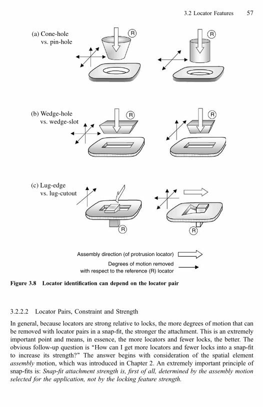
3.2.2.2 Locator Pairs, Constraint and Strength
In general, because locators are strong relative to locks, the more degrees of motion that can
be removed with locator pairs in a snap-fit, the stronger the attachment. This is an extremely
important point and means, in essence, the more locators and fewer locks, the better. The
obvious follow-up question is ‘‘How can I get more locators and fewer locks into a snap-fit
to increase its strength?’’ The answer begins with consideration of the spatial element
assembly motion, which was introduced in Chapter 2. An extremely important principle of
snap-fits is: Snap-fit attachment strength is, first of all, determined by the assembly motion
selected for the application, not by the locking feature strength.
Assembly direction (of protrusion locator)
Degrees of motion removedwith respect to the reference (R) locator
(a) Cone-holevs. pin-hole
RR
(b) Wedge-holevs. wedge-slot
R R
(c) Lug-edgevs. lug-cutout
R R
Figure 3.8 Locator identification can depend on the locator pair
3.2 Locator Features 57

Locator pair selection for a given application is a function of the assembly motion. We
can identify the ability of each of the five generic assembly motions to maximize the DOM
removed by locators and minimize DOM removed by locks.
As a general rule, locator pairs that remove the most degrees of motion (DOM) are
desirable from a design efficiency standpoint. But combining too many of these in one
interface will cause over-constraint. Another desirable characteristic of a locator pair is that it
help resist any possible forces in the separation direction. The only locator pairs with this
(a) Forces and lines-of-action
(b) A catch-edge locator pair
(d) An external force in the -y direction is resisted by the catch’s reaction force in the +y direction
(c) The edge is positioned in the -y direction by the catch acting in the +y direction
Line-of-action
(e) Constraint is both position and strength
Line-of-actionLine-of-
action
y
x
F
R R
x
yx
yz
F
Figure 3.9 Terminology
58 Constraint Features [Refs. on p. 94]

(e) Catches of opposite sensewith parallel lines-of-action
(a) Example: catches actingagainst edges
(c) Catches are co-linearand of the same sense
(b) Catches are co-linearand of opposite sense
(d) Catches have the same senseand parallel lines-of-action
(f) Catch lines-of-actionare perpendicular
Figure 3.10 Lines-of-action
3.2 Locator Features 59

ability are the lug-edge, lug-cutout and living hinge. There are other high-strength snap-fit
arrangements, but these three are unique in their use of a locator feature to help carry load in
the removal direction. The only assembly motion that supports this ability is the tip, Fig.
3.11.
Table 3.2 shows how the (recommended) locator pairs from Table 3.1 are related to
degrees of motion removed and assembly motion.
When considering the overall effect of assembly motion on locator and lock pair
selection, the potential for degrees of motion removed by locators is highest with the slide,
twist and pivot motions, next highest for a tip motion and lowest for the push assembly
motion, Table 3.3. This is strictly a function of how all of the locator pairs can be arranged in
the interface to accommodate the assembly motion. Note that while the slide, twist and pivot
motions may remove the highest DOM in some scenarios, the tip motion is preferred from a
total optimization standpoint. As a general rule, the push assembly motion, probably the
(a) A push motion requires that separation forces be resisted by locks
Fs
Assembly
Separation
(b) A tip motion allows some separation forces to be resisted by locators
Fs
Separation
Assembly
Figure 3.11 Assembly motion and constraint feature selection
60 Constraint Features [Refs. on p. 94]

Table 3.2 Locator Pairs, Degrees of Motion, and Assembly Motion Summary
Notes Locator pair DOM Assembly motion
removed
Push Slide Tip Twist Pivot
* p-s Track 10
* Living Hinge 10
v-v Cutout-Cutout 5
p-v Cone-Hole 5
p-v Lug-Cutout 4
p-v Pin-Hole 4
p-v Wedge-Slot 3
p-v Catch-Cutout 3
s-v Surface-Cutout 3
s-v Edge-Cutout 3
p-v Pin-Slot 2
p-s Lug-Edge 2
p-v Tab-Slot 2
p-s Tab-Edge 1
p-p Catch-Catch 1
p-s Catch-Surface 1
p-s Catch-Edge 1
s-s Surface-Land 1
s-s Surface-Edge 1
s-s Land-Edge 1
s-s Edge-Edge 1
* Special case
s-s surface-surface
s-v surface-void
p-s protrusion-surface
p-v protrusion-void
v-v void-void
p-p protrusion-protrusion
Bold ( ) indicates possible use as first engaged pair for the assembly motion.
Light ( ) indicates use as second or third engaged pair for the assembly motion.
Po
ssib
lelo
cato
rp
airs
3.2 Locator Features 61

most frequently used motion, should be avoided whenever possible because it requires the
most degrees of motion removed by the lock features.
3.2.2.3 Locator Pairs and Ease of Assembly
The part assembly motion will require selection and orientation of locator pair combinations
that permit assembly. A typical compatibility problem is a situation in which the designer
fails to recognize that the locator pairs in the attachment will not allow the assembly motion
to occur as anticipated. This situation was discussed in Chapter 2 and illustrated in Fig. 2.7.
Thinking about the application in terms of assembly motion has a number of advantages. In
addition to encouraging constraint feature decisions leading to maximum strength, it
increases design creativity (see Chapter 7) and designing with the available assembly
motions in mind will eliminate the possibility of motion=access=constraint feature
compatibility.
The first locators considered during design should be the one(s) that make first contact
during assembly. This locator pair(s) should also provide the guidance function (a required
enhancement) as shown in Fig. 3.12. Another advantage of the lug feature is shown here;
lugs can serve as assembly guides as in Fig. 3.12b. No additional guide enhancements, like
the pins in Fig. 3.12a, are needed. If a pilot is necessary, the first locator pair can also
provide that function. Pilots ensure that the mating part can only be assembled to the mating
part in the correct orientation. These and other enhancements are discussed in detail
in Chapter 4. Once these first locator pairs are in place, the remaining locators can be
added.
3.2.2.4 Locator Pairs and Dimensional Control
Some pairs in an application may be identified as ‘‘position-critical’’ because they will
control important positioning or alignment behavior of the parts. For this reason, they will be
potential sites for fine-tuning the attachment. Keep this in mind as these sites are identified
and use caution if two natural locators make up a position-critical pair where fine-tuning
Table 3.3 Assembly Motion and Degrees of Motion
Best case scenario Worst case scenario
Assembly
Motion
Maximum
possible DOM
removed by
all locators
Remaining
DOM to be
removed by
locks
Minimum
possible DOM
removed by
all locators
Remaining
DOM to be
removed by
locks Ease of Use
Slide 11 1 10 2 Limited by basic shapesTwist 11 1 10 2 Limited by basic shapesPivot 11 1 10 2 Limited by basic shapesTip 10 2 10 2 High adaptabilityPush 7 5 7 5 High adaptabilityDOMTOTALS 12 DOM 12 DOM
62 Constraint Features [Refs. on p. 94]
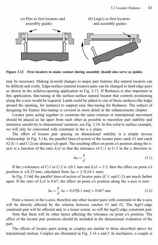
may be necessary. Making in-mold changes to major part features like natural locators can
be difficult and costly. Edge-surface (natural locator) pairs can be changed to land-edge pairs
as shown in the solid-to-opening application in Fig. 3.13. If flushness is also important in
this application, fine-tuning at the surface-surface natural locator that controls positioning
along the z-axis would be required. Lands could be added to one of those surfaces (the ledge
around the opening, for instance) to support easy fine-tuning for flushness. The subject of
designing for feature fine-tuning is covered in more detail in the enhancements chapter.
Locator pairs acting together to constrain the same rotation or translational movement
should be placed as far apart from each other as possible to maximize part stability and
minimize sensitivity to dimensional variation; see Fig. 3.14. In this solid to surface example,
we will only be concerned with constraint in the x–y plane.
The effect of locator pair spacing on dimensional stability is a simple inverse
relationship. In Fig. 3.14c, the parallel lines-of-action of the locator pairs catch #1 and catch
#2 (C-1 and C-2) are distance (d) apart. The resulting effect on point a’s position along the x-
axis is a function of the ratio h=d so that the tolerance of C-1 to C-2 in the y direction is:
Da ¼ h
dð3:1Þ
If the y-tolerance of C-1 to C-2 is �0:1 mm and h=d ¼ 2:5, then the effect on point a’s
position is �0:25 mm; calculated from Da ¼ 2:5ð�0:1 mmÞ.In Fig. 3.14d, the parallel lines-of-action of locator pairs (C-1 and C-2) are much farther
apart. If the ratio of h=d is 0.67, the effect on point a’s position along the x-axis is now:
Da ¼ h
dda ¼ 0:67½0:1 mm� ¼ 0:067 mm ð3:2Þ
Point a moves in the x-axis, therefore any other locator pairs with constraint in the x-axis
will be directly affected by the relation between catches #1 and #2. The lug#1-edge
constraint pair will be affected and, to a lesser extent, so will the lug#2-edge constraint pair.
Note that there will be other factor affecting the tolerance on point a’s position. The
effect of the locator pair positions should be included in the dimensional evaluation of the
part.
The effects of locator pairs acting as couples are similar to those described above for
translational motion. Couples are illustrated in Fig. 3.14 e and f. In mechanics, a couple is
(a) Pins as first locators andassembly guides
(b) Lug(s) as first locatorsand assembly guides
Figure 3.12 First locators to make contact during assembly should also serve as guides
3.2 Locator Features 63

defined as two equal forces, of opposite sense, having parallel lines-of-action. Couples act to
produce a pure rotational force or prevent rotational motion.
When possible, the position-critical locator pairs should be used as the datum for
dimensioning all the other constraint pairs in the interface. The datum for the position-
critical locators should be the related alignment site.
To minimize the effects of mold tolerances and plastic shrinkage, position-critical locator
pairs should be placed as close as possible to the site where alignment is required.
X
YZ
(a) Positioningrequired in thex-y plane
Solid to opening gap mustbe precise and uniform
Edge
Surface
Lands
(b) Surface-edgealternative
(c) Land-edgealternativeis preferred
Figure 3.13 Adding lands to a surface for easy fine-tuning
64 Constraint Features [Refs. on p. 94]
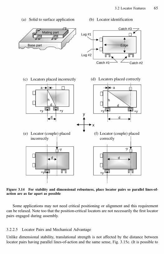
Some applications may not need critical positioning or alignment and this requirement
can be relaxed. Note too that the position-critical locators are not necessarily the first locator
pairs engaged during assembly.
3.2.2.5 Locator Pairs and Mechanical Advantage
Unlike dimensional stability, translational strength is not affected by the distance between
locator pairs having parallel lines-of-action and the same sense, Fig. 3.15c. (It is possible to
(c) Locators placed incorrectly
+y+y
a
d
hd
(d) Locators placed correctly
+y+y
d
hd
a
(f) Locator (couple) placedcorrectly
(e) Locator (couple) placedincorrectly
+y
-y
d
-y
d
+y
(a) Solid to surface application
Base part
Mating part
(b) Locator identification
Catch #3
Catch #1 Catch #2
Edge
x
y
Lug #1
Lug #2
Figure 3.14 For stability and dimensional robustness, place locator pairs so parallel lines-of-action are as far apart as possible
3.2 Locator Features 65

(a) Application with rotationaland translational forces
X
YZ
x
yCatch #3Base part
Mating part
Catch #1 Catch #2
Lug #1
Lug #2
F-y
F-x
R+x
R+x
R+yR+y
(b) Locatoridentification
(c) Locators reacting totranslational forces
(d) Locators reacting torotational forces
z
R+y
R-y
Figure 3.15 For strength, place locator pairs acting as couples as far apart as possible
66 Constraint Features [Refs. on p. 94]

remove translational movement along an axis with one locator pair.) For removing degrees
of motion in rotation, however, two locator pairs must work together as a couple and, as with
positioning, distance does have an effect. For maximum mechanical advantage against
rotational forces, locator pairs acting together as a couple should be placed with their
(parallel) lines-of-action as far apart from each other as possible, Fig. 3.15d.
3.2.2.6 Locator Pairs and Compliance
Compliance is treated as an enhancement and is discussed in detail in Chapter 4. For our
purposes here, it is sufficient to define compliance as tolerance to dimensional variation. In
other words, designing compliance into the snap-fit interface allows us to use normal
tolerances and maintain a close, rattle-free fit between parts.
Compliance can have an effect on a locator pair’s strength or positioning capability.
Caution is required if compliance must be designed into position-critical or load-carrying
locator pairs.
3.2.2.7 Locators Summary
Locators are strong and inflexible constraint features. Their job in a snap-fit is to provide
both positioning of the mating to the base part and strength to prevent motion under external
forces.
This section introduced locators as individual features and then explained how they
operate in a snap-fit as locator pairs. Functional issues and design rules associated with
locator pairs in an application were then explained.
3.3 Lock Features
Locks are the other constraint features and they have traditionally represented snap-fit
technology. To many designers, lock features, particularly cantilever hooks, are snap-fits.
However, at the attachment level, locks are just one part of the system. Locks hold the
mating part to the base part so the strong locating features can do their job. Along with
locators, locks are the ‘‘necessary and sufficient’’ features for a snap-fit attachment. From the
snap-fit definition:
Locks are relatively flexible features. They move aside for engagement then return toward their
original position to produce the interference required to latch parts together.
The fundamental problem in snap-fit design is that locks must be weak in order to deflect
for assembly yet strong enough to prevent part separation. Sometimes locks should release
but only under certain conditions. These complex and sometimes conflicting requirements,
plus the need for analysis of deflection and strength, make lock features much more difficult
to design than locators.
3.3 Lock Features 67

3.3.1 Lock Feature Styles
Locks are identified and grouped by their fundamental differences in assembly and retention
behavior. These differences are most obvious when we consider the calculations necessary
for evaluating assembly and retention behavior. Most locks require some form of flexible
behavior to permit assembly. Retention behavior is expected to be rigid until or unless
disassembly is desired. It is logical to infer varying degrees of retention performance
depending on the nature of the retention behavior and, indeed, we find that the effectiveness
of bending is far less than tensile, compression or shear behavior in resisting lock release.
Lock styles are defined here in a general order of usage. The cantilever beam style is by
far the most commonly used lock feature. Trap and planar locks are also relatively common.
Annular and torsional locks are less common. Brief definitions of the five styles of flexible
lock are given here then are followed by detailed discussion of each.
� Cantilever beam locks engage through beam bending and retain through the mechanics
of beam tension and bending or beam tension and shear.
� Planar locks involve one or two deflecting walls, usually with an edge and a catch on the
walls. They engage through plate deflection and retain through shear or compression
strength and plate mechanics.
� Trap locks engage through beam bending (like the cantilever beam locks) but they retain
through beam compression. This is a significant difference and we will see that traps can
be extremely strong locks.
� Torsional locks use torsional behavior for assembly deflection. Retention also depends
on the nature of the torsion member.
� Annular locks use interference between concentric ridges on the internal and=or external
walls of cylinders and rely on radial elasticity for assembly and retention strength.
The assembly and retention behaviors are much different for each of these lock styles.
This makes each style better suited for some applications and worse for others. Keep in
mind, however, that for many applications, the lock style must be selected to satisfy other
requirements such as available space for lock deflection, die movement for part
manufacturing and access for assembly. The most feasible lock style may not always be
the best lock style. But the versatility and variety of lock features allows many options and
solutions to a design situation.
As with locators, note that the parent material, such as a surface, on which a lock is
mounted is not considered part of the lock feature. If the parent material provides constraint,
it is considered a locator feature. For clarity and illustrative purposes, it is usually convenient
to show a lock feature with a surface, just remember it is not part of the lock.
3.3.2 Cantilever Beam Locks
The cantilever beam style lock is by far the most common locking feature and it exists in
infinite variety. Because it is the most common lock style we will spend much more time on
it than on the others. For the same reason, when appropriate to do so, it is used throughout
68 Constraint Features [Refs. on p. 94]

the book when a lock is needed to complete an example or an illustration. Many principles
of lock behavior, particularly those associated with the retention mechanism, introduced in
the cantilever beam section will also apply to the other lock styles.
All locks have two major components, a deflection mechanism that allows for assembly
and separation and a retention mechanism where contact occurs with the mating constraint
feature, Fig. 3.16. It is helpful to consider them separately.
3.3.2.1 The Deflection Mechanism
In a cantilever lock, the deflection mechanism is a beam and there are as many kinds of
deflection mechanisms, as there are possible beam shapes and sections. Some of the more
common beam shapes are shown in Fig. 3.17a. The beam can also vary by section and some
of the more common beam sections are shown in Fig. 3.17b. Analysis of beam behavior for
assembly is based on the classical bending equations for a cantilever beam fixed at one end.
Analysis for retention depends the retention mechanism style.
The deflection mechanism is a beam
The retention mechanism isa catch
Figure 3.16 Major parts of a lock feature
(b) Common sections
Square Rectangular Oval Round
Trapezoid ‘C’ ‘I’ ‘L’
(a) Common shapes
StraightThickness
AngularWidth
Tapered
Width and thickness
Figure 3.17 Common beam shapes and sections
3.3 Lock Features 69

By far, the most common lock configurations use beams similar to those shown in Fig.
17a with a rectangular section. The other sections are possibilities and may be useful in
solving a unique problem, but they are not generally recommended because they can make
analysis more difficult and=or add complexity to the mold.
3.3.2.2 The Retention Mechanism
The retention mechanism on the beam can be selected independently of the beam itself. This
increases the cantilever lock design options because beam and retention mechanism styles
can be mixed to suit the application. The most common retention mechanism is some form
of protrusion style locator, as shown in Fig. 3.18. When the retention mechanism is a
protrusion, the cantilever lock is called a hook because it ‘‘hooks’’ over an edge to engage.
The hook style cantilever locks must, of necessity, resist separation through beam bending.
The inherent weakness of the hook lock is that when separation force is applied to the
lock, the reaction force cannot be along the neutral axis of the beam, regardless of the shape
of the mechanism. As shown in Fig. 3.19, there will always be an offset (d). Thus the hook is
destined to bend. Unfortunately bending is the cantilever beam’s weakest direction for
resistance to deflection, Fig. 3.19a.
Even non-releasing hooks with a retention face angle at or near 90� can release under a
sufficiently high force. When a non-releasing hook does release under load, the typical
pattern of release begins with initial distortion of the beam at the retention mechanism. This
causes a reduction in the retention face angle which then enables additional slippage along
the retention face and beam bending for release, Fig. 3.19b. The kinds of hook failures
shown in Fig. 3.19c are very unlikely unless the hook end is restrained from rotating.
When an angle greater than 90� is used on both the hook and the mating feature, then
high strengths are possible, Fig. 3.19d. This kind of lock application is frequently found on
the closure buckles of soft-sided hand baggage like children’s backpacks, book bags and
laptop computer cases and they are quite strong. It does require enough clearance or
Figure 3.18 Common retention mechanisms based on protrusion-like locators
70 Constraint Features [Refs. on p. 94]

d
(a) Bending resistance to separation
(b) A non-releasing hook will not prevent separation
d
Localdistortionoccurs athook end
Final releaseoccurs with
general beambending
At a sufficientlyhigh separation
force
(c) Highly unlikely failure modes
Shearfailureunder
the catch
Tensilefailureof thebeam
(d) A retention face with a reverse angle can prevent separation in a non-releasing hook.
Reverseangle resiststhe distortionthat causes
release
Must haveclearance toengagebeyond thecatch andreturn
Design toensurecontact atbase ofthe catch
Contactat point ofcatch willweakenhook
A commonapplication is abuckle closure
Figure 3.19 The inherent weakness of a hook-style cantilever lock
3.3 Lock Features 71

compliance in the system to allow the lock face to move past the engagement point and then
return. For this reason, it is not practical in many applications.
A cantilever lock that uses void or edge-like retention mechanisms at the end of the
beam is inherently stronger than the beam=catch hook, Fig. 3.20. This lock style is called a
‘‘loop’’ [1] because it somewhat resembles a loop of rope thrown over a post. Just like a rope,
which has no strength in bending but is extremely strong in tension, the loop version of the
cantilever lock can have extremely high retention strength because it relies on tensile, not
bending, strength for retention. The ‘‘T’’ and ‘‘L’’ configurations are simply variations of the
basic loop. A ‘‘T’’ is a loop split down the middle and reconnected along the outside edges;
an ‘‘L’’ is one-half of a loop.
When a loop is used as a non-releasing lock, the reaction force is in line with the neutral
axis of the beam and no bending can occur. Instead, retention strength is determined by the
loop’s dimensions and the tensile and shear strengths of the materials that make up the lock
pair, Fig. 3.21. This characteristic means the loop style lock can always provide better
Specify a radius at all corners.
Figure 3.20 The loop-style cantilever lock
Reaction force againstseparation is along the
neutral axis of the beam
The beam is in tension, not bendingFigure 3.21 Retention strength advantage of the loop-style cantilever lock
72 Constraint Features [Refs. on p. 94]

retention in a given application than a hook. Often the mating feature to a loop hook in the
lock pair is a catch, which is also an inherently strong feature. The loop hook and catch
together can be an extremely strong lock pair and, unlike a hook lock, tends to be resistant to
release under shock loading.
In the case of releasing locks, the reaction force is no longer along the neutral-axis of the
loop, but the loop still has retention advantages. In addition to advantages in retention, the
loop enjoys other advantages over the hook. It inherently has a more desirable force-
deflection signature for assembly as discussed in the following sections. These additional
retention and assembly characteristics will be discussed shortly.
The loop also requires less clearance for deflection and can deliver equivalent or better
retention performance when space for lock deflection is limited.
An issue unique to the loop is the likelihood of forming a knitline somewhere in the loop
during the manufacturing process. Knitlines occur where two fronts of plastic material meet
as the melt flows through the mold. The loop’s shape practically guarantees this will happen,
Fig. 3.22a. Knitlines may reduce the strength of the material at that point. Test data indicates
the effect may be as much as a 65% strength reduction depending on the material and the
absence or presence of a filler [2]. In addition to the material itself, the amount of strength
reduction depends on the temperature (i.e. viscosity) of the fronts and the ability of the
surface layers of the two fronts to merge. The strength reduction is most dramatic in filled
materials; the fibers will not flow across it so the knitline consists only of the polymer
(a) Knitlines are almost guaranteed in loops
(b) Location makes a difference
Flow path
Knitlines
Gate
Time
Close to gate,melt is hottestand knitline willbe stronger
Loop shape or otherpart features mayaffect knitline location
Farther from gate, melt iscooler and more viscous;knitline will be weaker andmay move
Figure 3.22 Knitlines in the loop-style cantilever lock
3.3 Lock Features 73

material, making it significantly weaker. In the tests cited above, unfilled polypropylene
showed a 14% reduction and a 30% glass-filled polypropylene showed a 66% reduction in
strength. The unfilled and 40% glass-filled nylon 66 test results were 3% and 48%
respectively. (These results occurred under specific test conditions and should not be
considered design data.)
Loops having identical shapes but located in different areas of the same part can have
different levels of knitline strength and the knitlines can occur at different locations, Fig.
3.22b. This is due to local flow characteristics and because the melt temperature at a given
point depends on its distance from the gate and cooling effects of the mold along the flow
path.
Beall [2] recommends adding a drawing note indicating ‘‘No weldline (knitline) in this
area’’ as a precaution for any highly loaded area of a part. This is a good idea, but the shape
of the loop may make knitline prevention impossible. In general, the designer should accept
that knit lines will occur in the loop and design to compensate for them; possible designs are
shown in Fig. 3.23. Study and testing of prototype parts will indicate actual knitline
location(s) and allow verification of the effectiveness of the solutions.
As mentioned elsewhere, it is good design practice to specify fillets and radii on all
corners, both internal and external, on plastic injection-molded parts. This is especially
critical in loops, where a sharp corner in the opening becomes a weak site due to molded-in
stresses and also a stress riser under loads. They may not always be shown in the
illustrations, but always specify a radius on all corners of a loop.
3.3.2.3 Cantilever Lock Examples
Some additional examples of cantilever locks are shown in Fig. 3.24. Although they are
shown as extending at 90� from the plane of a wall, any angle is possible. Cantilever locks
can also extend from an edge at any angle or they can be in-plane, extending from an edge or
lying within the boundaries of a wall, Fig. 3.25.
3.3.2.4 Locators as Cantilever Locks
We recognize lock features by their deflection and, in general, we think of that deflection in
terms of relatively large movements. However, locators can sometimes be used as locks
Increase the cross-sectional area
Adjust the flow to bias the knitline toward shearrather than tensile stress and move it away from thehighest stress areas (usually corners and anywherebending occurs)
Figure 3.23 Compensating for knitline weakness
74 Constraint Features [Refs. on p. 94]

(h) The basic loop (i) Another example of a retention feature turned 90o
(a) A common hook, showing reasonably good proportions
(c) Beam is too short relative to thick-ness and insertion face is too steep
(b) Extra long beam may warp and is too thinrelative to length for good retention strength
(d) Turning the beam back on itself gives extra length for deflection in confined spaces but may be difficult to mold
(e) Another versionof a curved beam
(f) Any of these examples can also be a loop style lock
Locks with this mark are not recommended or require extra care.
(g) Turning the beam 90o
relative to the catch can improve performance significantly; see Chapter 5
Figure 3.24 Variations of the cantilever lock
3.3 Lock Features 75
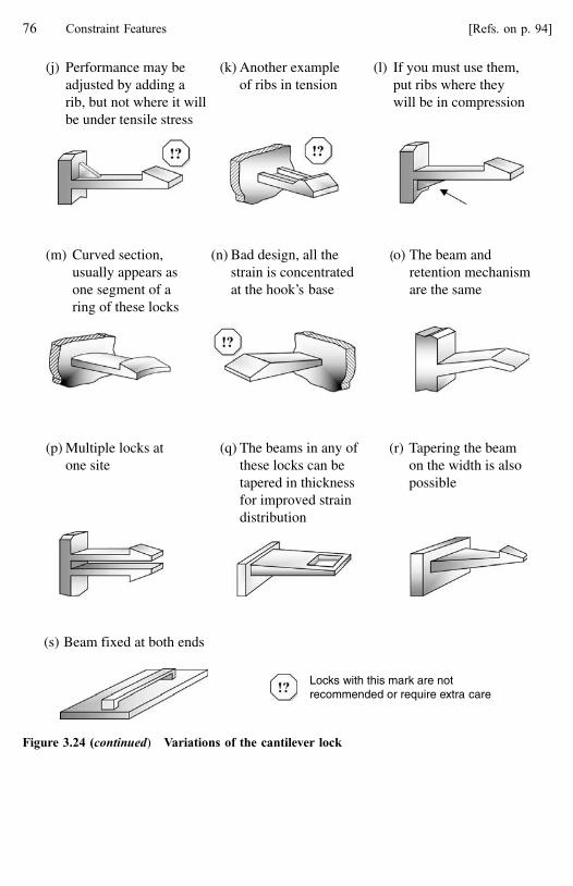
Locks with this mark are notrecommended or require extra care
(p) Multiple locks atone site
(r) Tapering the beamon the width is alsopossible
(q) The beams in any ofthese locks can betapered in thicknessfor improved straindistribution
(m) Curved section,usually appears asone segment of aring of these locks
(o) The beam andretention mechanismare the same
(n) Bad design, all thestrain is concentratedat the hook’s base
(l) If you must use them,put ribs where theywill be in compression
(j) Performance may beadjusted by adding arib, but not where it willbe under tensile stress
(k) Another exampleof ribs in tension
(s) Beam fixed at both ends
Figure 3.24 (continued) Variations of the cantilever lock
76 Constraint Features [Refs. on p. 94]

when the required deflections are very low. The two requirements for these applications are
an assembly motion that involves sliding (the slide, twist and pivot motions) and low or no
force in the separation direction. Figure 3.26 shows some examples. In all these cases, the
(lock) locator feature deflects over a small interference feature then returns to its relaxed
state. The principles of constraint, beam deflection, tolerances and strength that apply to all
lock pairs still apply.
3.3.2.5 Lock Pairs
As with locators, a lock feature on one part requires a mating feature on the other part.
Together they make up a lock pair. In a lock pair, the mating feature is usually a locator
feature such as an edge or catch. But there is no reason why, in some cases, it cannot be
another lock. This can be useful when getting enough deflection out of only one feature is
difficult. Lock pairs are important because lock effectiveness is a function of both members
of the pair. We cannot isolate the deflecting lock feature and expect to understand or predict
its performance.
The deflecting member of a lock pair may be placed on either the mating part or on the
base part. Sometimes this is an economic=risk decision where it may be wise to put the lock
on the smaller and less expensive part because the lock may be subject to damage during
service=removal. Other times, lock placement is based on performance, putting the lock on
the part with the best material properties to support desired lock performance.
(a) Perpendicular to a wall (b) Perpendicular to an edge
(c) In-plane from an edge (d) In-plane within a wall
Figure 3.25 Lock orientation to parent material
3.3 Lock Features 77

Unlike locator pairs, lock pairs will usually only remove one DOM. For cantilever hooks,
traps and torsional locks expect lock strength only in the direction that resists separation.
Annular and planar locks can sometimes provide strength in more than one DOM.
In the following discussions of lock behavior, the lock is treated as engaging a locator
feature as the other member of the lock pair.
3.3.2.6 Cantilever Lock Assembly Behavior
With the common cantilever hook, the insertion face angle increases as the (hook) lock pair
is engaged, Fig. 3.27. This causes the assembly force signature to increase geometrically,
Fig. 3.28a. The resulting high final force can sometimes cause difficult assembly and
feedback to the operator may be poor. If this is the case, a profile added to the insertion face,
Fig. 3.29, can make the assembly signature more operator-friendly by reducing the
maximum assembly force and changing the ‘‘feel’’ of the lock. Depending on the shape of
the profile, the signature can be made to have a constant rate of change or a decreasing rate,
Fig. 3.28b and c. The latter will give an ‘‘over-center’’ feel to the assembly and is most
preferred for operator feedback.
(a) Slide motion and track (b) Twist motion and lugs or catches
(c) Pivot and lug (d) Lug and interference featureLug slides over rib and comesto rest against the stop
Figure 3.26 Locators as lock features
78 Constraint Features [Refs. on p. 94]

Figure 3.28 Typical assembly force-deflection signatures. Note that the maximum assemblyforce is lower at the same deflection in (b) and (c)
α
α
Lock deflection
Engage direction
The shape of the profile determines the force-deflection signature
Figure 3.29 Adding a profile to the hook insertion face
Lock deflection
Engage direction
α
α
Figure 3.27 Increase in the insertion face angle during assembly; the most common situation
3.3 Lock Features 79

The profile shape can be calculated to give the desired signature. A simplified calculation
(see Chapter 6) can be based on treating the beam as if it is bending from its base with no
curvature and no rotation of the hook end; often this is sufficient. More complex calculations
accounting for beam curvature and end rotation can be applied if desired.
In an application where the action is controlled-moveable, the customer may be using the
lock frequently. In this instance, the nature of the force-deflection signature can give the user
the perception of either high quality or poor quality. The insertion face should always have a
profile to improve user-feel and perceived quality and, again, an over-center signature as in
Fig. 3.28c is preferred. High assembly forces repeated many times in a moveable application
may also cause eventual damage to one or both members of the lock pair. An insertion face
profile can reduce the chances of long-term damage by reducing the maximum assembly
force.
Not all hooks exhibit this geometrically increasing assembly signature. If the nature of
the hook is such that the insertion face angle does not change with the assembly movement,
then the assembly signature will have a constant slope as shown by the loop style lock in Fig.
3.30. In this case too, the catch profile can be modified to give an over-center feel if desired.
One caution with respect to the loop design shown in Figs. 3.20a and b is that the walls
at the open retention area are relatively weak compared to the remaining part of the beam.
Design to ensure that assembly bending and strain is not concentrated in those walls. A
solution is to extend the opening to the base of the beam as in Fig. 3.20c.
3.3.2.7 Cantilever Lock Retention and Disassembly Behavior
Some principles of retention were introduced with the discussion of the retention
mechanism, but there are a few more that should be covered now. As with the assembly
behavior, this is a qualitative discussion of cantilever hook behavior. Quantitative analysis of
assembly and retention behavior is covered in Chapter 6.
As a general rule, it is recommended that lock features carry no significant forces in the
separation direction. This is because locks tend to be relatively weak in that direction
although, as we saw with the loop, some cantilever style locks can be quite strong. Design
reality, however, is that many locks will, from time to time, be required to carry forces in the
separation direction.
Figure 3.30 Assembly behavior of the loop-style lock
80 Constraint Features [Refs. on p. 94]

It is important to differentiate between the kinds of forces to which a lock might be
subjected. Separation forces may be low, which is good, but if they are continuous and long-
term they may result in plastic creep and lock release. Forces may be high but transient and,
in a properly designed application, have no effect. In an application with poorly designed
locks, the same transient forces may cause unintended separation. It is these transient forces
we are concerned with here. Of course, the terms ‘‘high, low, long-term, short-term’’ are
relative and depend entirely on the mechanical properties of the plastic(s) in any given
application.
One of the most common mistakes made in snap-fit design is to use the lock to react
against forces other than those in the separation direction. This results in an under-constraint
condition because most locks, and certainly the cantilever hook, are intended to constrain in
one direction only, the separation direction, Fig. 3.31. Always ensure that locator features are
present to carry these other forces. Generally, the locators should be close to the lock for
maximum effect.
What happens during application of a transient force to a lock? The energy is either
absorbed by the locking system or the lock releases. The goal is to absorb the energy before
the lock releases and without permanent damage to the lock.
Remember, even some locks designed to be non-releasing will release under sufficient
force; refer back to Fig. 3.19b.
Figure 3.32a shows a typical cantilever hook. It has an angle less than 90� on the
retention face, indicating it is probably a releasing lock. But, as with the lock in Fig. 3.19b,
the mechanics of separation will be the same as for a non-releasing lock. As a separation
force is applied, the hook begins to bend and the retention face angle decreases, Fig. 3.32b.
(This is the opposite of the effect beam deflection had on the insertion face angle.) As the
retention face angle decreases, its contribution to resisting the separation decreases. This
decrease in the retention face’s contribution is normally offset by the continuously increasing
deflection force and the separation resistance continues to increase as illustrated in the three
possible retention strength-deflection signatures shown in Fig. 3.32c. When calculating
retention behavior, it is a good idea to calculate performance at partial release and just before
final release. This will expose the situations where the angle effect dominates and the
separation force drops once deflection begins.
Note that the parent materialis not part of the lock feature
No bending forces
Figure 3.31 Locks should resist forces in the separation direction only
3.3 Lock Features 81

Retention performance can sometimes be improved by adding a profile to the retention
face, Fig. 3.33a. The profile compensates for the change in retention face angle and ensures
that the instantaneous angle remains constant, Fig. 3.33b. This allows the lock to absorb
more energy before releasing as shown in the force-deflection signature in Fig. 3.33c. When
comparing force-deflection signatures, picture the separation energy absorbed as being
proportional to the area under the curve. The signature can be modified for maximum
effectiveness by adjusting the profile. The only limitations to the retention face profile are
clearances for assembly and molding.
The retention face profile is a relatively subtle change and can be effective when forces
are of very short duration, as might occur in a drop test of an electronic device. The principle
of energy absorption can also be applied using some locators as spring-like features in the
system. This is discussed in Chapter 4 in the section on compliance enhancements.
Another solution to preventing release is to use the loop style lock because it is
inherently stronger both as a releasing and as a non-releasing lock. We have already
discussed a non-releasing loop’s retention behavior, but how will a releasing loop behave?
Figure 3.34a shows a releasing loop and Fig 3.34b shows its separation force-deflection
(c) The separation force-deflection signature is a function of decreasing angle andincreasing deflection force and may be of increasing, constant or decreasingslope
To identify the shapeof the signature amid-point must becalculated in additionto the final lockrelease pointR
eten
tion
stre
ngth
Deflection
Lockdeflection
(a) Separation force initiatesbeam bending
(b) The retention face angle gets smalleras the beam bends
Separationforce
β
Deflection force
β β
Figure 3.32 Effect on retention strength as the beam deflects
82 Constraint Features [Refs. on p. 94]

(c) The improved force-deflection signaturemaximizes the areaunder the curve
(a) Profile added tothe retention face
Lockdeflection
Separationforce
(b) The instantaneous retention face angle does notchange as the beam bends
β ββ
Ret
entio
nst
reng
th
Deflection
Lock release
Improvedsignature
Figure 3.33 Benefits of a retention face profile
(a) An acute angle on thecatch retention facemakes this a releasinglock
Separationdirection
(b) With a flat retentionface, release resistanceincreases at a relativelyconstant rate
Deflection
Ret
entio
nst
reng
th
Lockreleasepoint
(c) With a concaveprofile on theretention face
Ret
entio
nst
reng
th
Deflection
Lockreleasepoint
Figure 3.34 The retention force-deflection signature of the loop-style lock
3.3 Lock Features 83

signature. Even with a flat face on the catch, the retention force becomes greater as
deflection occurs because the beam requires more force as it deflects. Adding a profile to the
catch retention face will further improve energy absorption.
There are two more methods for making the cantilever lock stronger. One very effective
and simple method is illustrated in Fig. 3.24g and Fig. 3.24i. The catch retention feature on
the beam has simply been turned 90�. This change makes the hook’s engage direction
perpendicular to the long axis of the beam. This allows the beam to bend along the thin
section for low assembly forces and low strain, yet resist separation across the thicker section
of the beam’s width. This is called ‘‘decoupling’’ and is discussed in detail in Chapter 5.
Turning the catch 90� can also allow use of a cantilever lock where part clearance or mold
design constraints prevent the use of a more conventional lock. The loop style lock can also
be used in this manner.
The last method for improving cantilever lock performance is to add retention
enhancements to provide additional support or strength to the lock. Retention enhancements
are discussed in Chapter 4.
This concludes discussion of the cantilever style lock. It is the most common lock and
deserves the most attention. Many of the fundamental principles for lock behavior were
introduced here for the cantilever lock and will not be discussed again as the other lock
styles are explained.
3.3.3 Planar Locks
Planar locks are so named because they are found on walls or surfaces (i.e. planes), Fig.
3.35. The walls are generally thin relative to their length and width so their behavior in
deflection is plate-like. Therefore, the engagement and retention behavior of planar locks is
described through the mechanics of plate deflection. A planar lock usually involves a catch
on one part and an edge on the other part as the lock pair. One or both of the features may be
on a deflecting wall on their respective parts.
These locks can be made relatively strong but, because at least one member of the lock
pair must sit on a surface, the reaction force will always be off of the neutral axis. This
creates the potential for distortion of the wall under high separation force and lock release.
May be an edgecreated by arecess or by athrough hole
Frequently a catch
Figure 3.35 Planar locks
84 Constraint Features [Refs. on p. 94]

The weakness of the thin wall may require local support in the form of ribs or additional wall
thickness in the area of the lock. An additional consideration with these locks is that both
mating features can be on deflecting walls. This means both walls will deflect for
engagement, reducing assembly forces and strains; but they can also deflect for separation,
weakening the attachment.
The principles of the insertion and retention face profiles and their effects on assembly
and separation force-deflection signatures are the same as for the cantilever hook. However,
the more extreme deflections of the cantilever beam are not likely to be found in a wall.
Because a wall is likely strong in two axes, a planar lock can be made to constrain in
three degrees of motion. In Fig. 3.36, the catch-cutout pair constrains in three DOM while
the other constraint pair is a catch-edge. A second catch-cutout pair would not be appropriate
here because it would create an over-constraint condition with the first.
3.3.4 Trap Locks
Traps engage through beam bending and retain through beam compression and=or bending
so, like cantilever beam locks, trap behavior is based on beam mechanics. Traps differ from
the beam locks, however, in both insertion and retention behavior, Fig. 3.37. A cantilever
beam lock engages with the mating feature moving toward the fixed end of the beam and
retains with the mating features moving away from the fixed end of the beam. Traps are just
the opposite, engaging with the mating feature moving away from the lock base and
retaining with the mating feature moving toward the lock base. These differences result in
some significant performance differences between these two lock styles.
Traps can be extremely strong and are ideal as non-releasing locks for applications where
parts are not intended for separation or where there is access from behind for manual release.
With careful attention to the retention face contour, they can also be designed as releasing
locks.
Traps seem to be quite common in solid-to-cavity, solid-to-opening and panel-to-
opening applications where mating part removal is not expected. However, they are not
limited to these applications, Fig. 3.38.
The beam shape in a trap is usually limited to variations of the straight cantilever beam.
The retention mechanism is normally the end of the beam itself or a retention face formed by
Catch tocutout is aplanar lockconstraining in3 DOM
Catch to edgeis a planar lockconstraining in
1 DOM
Figure 3.36 A planar lock can constrain in one or three degrees of motion
3.3 Lock Features 85
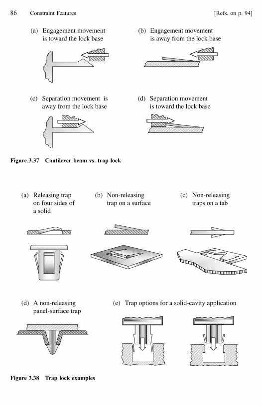
(a) Engagement movementis toward the lock base
(b) Engagement movementis away from the lock base
(c) Separation movement isaway from the lock base
(d) Separation movementis toward the lock base
Figure 3.37 Cantilever beam vs. trap lock
(a) Releasing trapon four sides ofa solid
(b) Non-releasingtrap on a surface
(c) Non-releasingtraps on a tab
(e) Trap options for a solid-cavity application(d) A non-releasingpanel-surface trap
Figure 3.38 Trap lock examples
86 Constraint Features [Refs. on p. 94]

deformation of the beam. However, any form of the cantilever beam style lock can also
become a trap when the direction of engagement is from the fixed end of the beam.
3.3.4.1 Trap Assembly Behavior
Because the trap lock’s insertion face angle decreases and the point of contact enjoys an
ever-increasing mechanical advantage as the trap is engaged, the assembly force signature
shows a decreasing rate of increase, Fig. 3.39. This makes the trap an operator-friendly
attachment because it tends to result in lower assembly forces and creates an over-center
action for improved assembly feedback.
3.3.4.2 Trap Retention and Disassembly
Traps can be either releasing or non-releasing depending on the retention mechanism. Like
the cantilever hook, a releasing trap resists separation through beam bending. Also like the
hook, release behavior is a function of the angle and shape of the retention face and the
coefficient of friction between the mating surfaces. There is one notable exception however.
Unlike the hook, as separation occurs, the trap’s retention face angle becomes steeper
resulting in improved retention performance, Fig. 3.40.
Asse
mbl
yfo
rce
Deflection
α
α
Figure 3.39 The trap lock assembly force-deflection signature
Ret
entio
nst
reng
th
Deflection
β
β
Figure 3.40 The trap lock retention strength-deflection signature
3.3 Lock Features 87

The non-releasing trap resists separation not through bending but through beam
compression and can be very strong, Fig. 3.41. The failure mechanism of these traps is beam
buckling and trying to force part separation will most likely damage the lock or the mating
part. If applications using non-releasing traps are to be serviced, some provision must be
made to allow access for trap deflection. A good example of the trap lock’s strength can be
found in the very common plastic tie-strap of the kind often used to bundle electric wires.
The plain end of the strap is inserted into the locking end and pulled to engage the ribbed
side of the strap with a ratcheting finger in the locking end. This is a trap mechanism and it is
very strong.
Traps can also be found on some luggage buckles as an alternative locking mechanism to
the cantilever hook. This kind of application (using a hook) is shown in Fig. 3.19d.
A non-releasing trap must ensure beam compression and protect against beam slippage
and damage due to separation forces. (An exception is when the application is to be tamper
evident and permanent damage to the lock is desirable or acceptable.) In the applications
Access to release the trap locks
Figure 3.41 Non-releasing trap application
(a) Separation force applied to an unrestrained trap lock
Beam damage
Beam slips and bends
(b) Use of a tang to restrain a trap lock
Beam cannot slip or bend, must buckle
Figure 3.42 Non-releasing trap reaction to separation forces
88 Constraint Features [Refs. on p. 94]

shown in Figs. 3.38d and 3.38e and in Fig. 3.41, the trap beams are prevented from slipping
outward because they are contained by corners. The only possible failure is beam buckling
which must occur at higher forces.
Fig. 3.42a shows the behavior of a non-releasing trap where beam movement is not
restricted. As the separation force is applied, slippage may occur immediately if friction is
insufficient. Or, once initial buckling occurs, the beam will slip on the mating surface. In
either situation, resistance to separation forces is reduced and permanent damage is likely at
much lower forces. Fig. 3.42b shows how a tongue or tang on the end of the lock beam can
ensure against slippage.
Figure 3.43 shows a design (found on an electrical connector) where such an extension is
used. We can assume the designer wanted a non-releasing trap to guarantee against
accidental separation of the connector but also wanted to protect the trap from damage due to
a hard pull on the wires leading into the connector. In this application, another interesting
behavior was noted; it may or may not have been intentional. Because of the nature of this
particular attachment, distortion can occur in the tracks when sufficient force is applied.
When the distortion is sufficient, the tang pushes against the connector body and causes the
beam to release. This behavior could prevent wire=pin separation in the connector.
A trap-like feature could also be added to a product strictly as tamper evidence and not
as a lock. In this case it could be extremely small and need only to survive assembly
deflection. Place it in a location where it is either visible before disassembly to ensure it is
still in-place or deflectable with a tool if the disassembler knows where=how to deflect it.
(Could ‘‘witness features’’ like this possibly become another group of enhancements?)
3.3.4.3 Traps and Lock Efficiency
Because lock feature design frequently involves a trade-off between assembly force and
retention strength, a way of evaluating locks with respect to this trade-off can be very useful.
The ‘‘lock efficiency’’ number provides a way of doing that. Lock efficiency is the ratio of a
(c) An unintendedpull on the wires
(d) Track distorts and thetang at the end of thebeam forces release
(e) Separation with nopermanent damage
(a) Connector is a solid-surfaceapplication with tracks and a trap
(b) As assembled
Figure 3.43 Non-releasing trap application
3.3 Lock Features 89

lock’s retention strength to its assembly force [3]. Lock efficiency values can be developed
for specific lock designs, but they are also useful for comparing the relative effectiveness of
various lock styles. By its nature, the trap lock is inherently capable of developing the
highest efficiency numbers of any lock style. As a general rule, if a trap lock can be used in
place of a cantilever hook style lock, use it. The cantilever loop lock style is also more
effective than the hook and has a higher lock efficiency rating.
EL ¼ FR
FA
ð3:3Þ
where EL is lock efficiency; FR is retention strength; FA is maximum assembly force.
Section 5.2 in Chapter 5 discusses ‘‘decoupling’’, the most effective method of
increasing lock efficiency.
3.3.5 Torsional Lock
Torsional locks involve primarily torsional deflection for assembly although there is often
some bending in the system as well. Retention depends on the stiffness of the torsion
member and on the retention mechanism.
As shown in Fig. 3.44, the torsional member is not necessarily round. Torsional locks are
relatively uncommon but are useful as an alternative to the cantilever style lock when
clearances or access make hook location for disassembly difficult. For example, in an
application where a hook must be flush with a panel and must be manually releasable (a non-
releasing lock), the seesaw action of the lock allows release from the blind side of the
retention mechanism.
Aside from the torsional deflection mechanism, the assembly and retention behaviors of
these locks are similar to the cantilever beam style lock or to the trap, depending on the
direction of mating feature engagement and release relative to the torsion member.
We are defining torsional locks as locks where the deflection mechanism is primarily
torsion and can be analyzed as such. There are some locks where questions can arise as to
their identification. In these locks, the installation deflection may be a combination of
torsional shear, bending and plate deflection. Retention may involve torsional shear, plate
deflection and either bending or compression. In these cases, evaluation of assembly and
retention behavior will depend on which one of the deflection mechanisms dominates, and a
thorough understanding of the interactions. An analysis which can evaluate these combined
effects may be required.
Figure 3.44 Torsional locks
90 Constraint Features [Refs. on p. 94]

3.3.6 Annular Lock
Annular locks involve interference between concentric ridges on cylinders and rely on radial
elasticity for assembly and retention. Tensile and compressive hoop stresses occur in the
lock features. An annular lock may be thought of as a catch wrapped around a cylinder and
an edge wrapped around another mating cylinder, Fig. 3.45.
Note that, by this definition, a circular arrangement of hooks or traps is not an annular
lock because it requires analysis of beam bending. Sometimes this arrangement is called
‘‘annular’’ in the literature. In that case, ‘‘annular’’ is a functional rather than a behavioral
definition.
Annular locks can be extremely strong (permanent or non-releasing) or they can be
releasing. A snap-on cap on a ball-point or felt-tip pen is a common releasing annular snap,
the caps on 35 mm film canisters are another. They can also permit (free) rotation in a
moveable application. Because annular locks, by definition, involve a locator pair (pin-hole,
Fig. 3.44a) or the entire mating part-base part system (solid-cavity, Fig. 3.44b) they will
constrain in more than one degree of motion. Normally, annular locks constrain in 5 DOM.
This is another difference from the circular hook or trap arrangement.
3.3.7 Lock Pairs and Lock Function
In Chapter 2, we introduced a descriptive element of a snap-fit called function. Function
describes what the locking feature(s) in a snap-fit attachment must do. Locking feature
function is explained in terms of action, purpose, retention and release. These generic
descriptions of locking requirements help us to categorize snap-fit applications for
benchmarking and organizing snap-fit application libraries.
Now that lock features have been defined, the reader should be able to see that, depending
on the design requirements and limitations, certain lock features and lock pairs will be
(a) Annular lock as apin-hole locator pair
(b) Annular lock as part of a solid-cavityapplication
Figure 3.45 Annular locks
3.3 Lock Features 91

preferable to others for a given lock function. Likewise, a lock pair can be over-designed or
over-engineered causing unnecessary engineering time and manufacturing cost. It is important
to balance the application requirements with the cost=capability of the various lock options.
3.4 Selecting a Locking Feature
Locking feature selection should be a calculated decision based on an understanding of the
application’s needs. The previous section described a number of locking feature styles. An
important question is now ‘‘How do I know which one to use?’’ The answer to that question
depends on a number of conditions in the application. They are:
� The desired ‘‘Function’’ of the lock feature. See the discussion in Section 2.3.1, Chapter 2.
� The ‘‘Demand’’ level of the application. See the definitions in Section 9.2 and the
discussion in Section 9.6.3 in Chapter 9.
� The application’s grip length. ‘‘Grip length’’ is the distance from the retention face of
the locking feature to the opposite (reacting) surface. For a cantilever hook-style lock, it
is the distance from the wall or edge at the base of the beam to the retention face of the
catch at the end of the beam. A short grip length will rule out use of the cantilever hook
style. A panel attaching to an opening in a relatively thin wall will typically be a short
grip length application.
� Molding requirements and the desire to keep the mold simple. Locks that do not require
die-action will be preferred over those that do. But, do not sacrifice reliability just to
avoid die-action.
� The need to have a low installation force (usually an ergonomic or a customer
satisfaction requirement) and, at the same time, high retention strength. See the
discussion of ‘‘decoupling’’ in Section 5.2, Chapter 5.
The cantilever hook is the most commonly used locking feature, yet many times it is not
the best feature for the application. See the ‘‘Harmful Beliefs’’ in Section 9.3 and Figure 9.5
in Chapter 9. Designers should be aware of the other locking feature styles and avoid simply
defaulting to the cantilever hook, particularly in short grip length and high demand
applications. Many times, other beam style locks (loop and trap) can be used in place of a
cantilever hook and provide much better retention.
Also keep in mind that the locking features on a particular application do not have to be
identical. It may be convenient for purposes of die simplicity or for performance reasons to
mix lock feature styles or sizes in one interface.
3.5 Summary
The purpose of this chapter has been to present a descriptive explanation of the various
constraint features. From this information, a designer should understand the fundamental
92 Constraint Features [Refs. on p. 94]

differences in constraint feature behavior and be able to select the appropriate constraint
feature styles when developing an application concept.
This chapter described the two major kinds of constraint features, locks and locators,
which are used in the snap-fit interface to create a constraint system. Constraint features
remove degrees of motion from the attachment and are the ‘‘necessary and sufficient’’
conditions for a snap-fit attachment.
3.5.1 Important Points in Chapter 3
� The fundamental problem in snap-fit design is that locks must be weak in order to deflect
for assembly yet strong enough to prevent part separation.
� Snap-fit reliability depends on establishing and maintaining a line-to-line fit between the
mating and base parts. Do not expect to get any significant or long-term clamp load in a
snap-fit.
� The rules for mechanical advantage and dimensional robustness that were introduced
and explained with the locator features are general rules for all constraint features and
they also apply to lock pairs.
� Some locator pairs can constrain in as many as 5 degrees of motion, others in as few as
one. Most lock pairs, planar and annular being the exceptions, can constrain in only one
degree of motion (the separation direction). Designing for a lock to constrain in
additional degrees of motion will leave the attachment under-constrained.
� The cantilever beam, planar and trap are the most common lock styles. Torsional and
annular are often special usage locks.
� A profile added to both the insertion and retention faces in a lock pair can significantly
improve assembly and retention performance.
� Caution, even non-releasing hooks will release under sufficiently high forces.
� Locators can be used as low-deflection locks, particularly when an assembly motion that
involves sliding (slide, twist and pivot motions) is present.
� Lock efficiency, the ratio of retention strength to assembly force, is a good indication of
inherent lock effectiveness.
3.5.2 Design Rules Introduced in Chapter 3
� Because of the tendency of plastic to creep, avoid long-term or sustained forces across
the snap-fit interface unless these forces are low and long-term performance is indicated
by analysis and verified by end-use testing.
� Use locators to carry all significant transient forces across the interface and arrange locks
so they do not carry transient forces in the separation direction unless they are permanent
locks or have special retaining capability.
� Locators should be the first constraint features added when developing the snap-fit
interface and the first locators considered should be the one(s) that make first contact
during assembly. This locator pair(s) should also provide the guidance function.
3.5 Summary 93

� Because locators are strong relative to locks, the more degrees of motion that can be
removed with locator pairs in a snap-fit, the stronger the attachment.
� The assembly motion selected for an application will determine the potential strength of
a snap-fit attachment. This is because locator pair selection for a given application is a
function of the assembly motion.
� The potential for degrees of motion removed by locators is highest with the tip, slide,
twist and pivot motions so they are generally preferred over the push motion. Of the four
preferred motions, tip is usually the most practical.
� When a beam lock is being considered, design to use loops or traps whenever possible.
In general, the hook style locks will have the lowest lock efficiency. Cantilever beam
loop style locks have much better efficiency than the hook, and the traps have the
highest.
� A loop or trap lock used with a tip assembly motion is a highly effective snap-fit
attachment concept and should always be considered as a design alternative.
� Where two natural locators make up a position-critical pair and fine-tuning may be
necessary, consider adding a discrete locator as one member of the pair.
� Maximize part stability and minimize sensitivity to dimensional variation by placing
constraint pairs constraining the same rotation or translational movement as far apart
from each other as possible.
� Maximize mechanical advantage against rotational forces by placing constraint pairs
acting as a couple so that their (parallel) lines-of-action are as far apart as possible.
� Specify a radius on all interior and exterior corners of constraint features. This applies to
the feature intersection with the parent material and to all corners within the feature
itself.
� Non-releasing trap locks must be protected from over-deflection and damage.
� Design compensation for knitline weakness into loop style locks.
References
1. Loops were described as a unique lock feature in Integral Fastener Design, Dave Reiff, Motorola Inc.,
Fort Lauderdale, FL.
2. Plastic Part Design for Economical Injection Molding, 1998, Glenn L. Beall, Libertyville, IL. Test data
reproduced from LNP Cloud, McDowell & Gerakaris, Plastic Technology, Aug. 1976.
3. Luscher, Dr. A.F., Design and Analysis of Snap-fit Features, from the Integral Attachment Program at the
Ohio State University, 1999.
94 Constraint Features

4 Enhancements
Enhancements were introduced in Chapter 2 as the second of two groups of physical
elements used in snap-fit attachments. They were also referred to several times during the
discussion of constraint features in Chapter 3. In this chapter all the enhancements are
presented and described in detail.
4.1 Introduction
Enhancements may be distinct physical features of an interface or they can be attributes of
other (physical) interface features. They improve the snap-fit’s robustness to variables and
unknown conditions in manufacturing, assembly and usage. In other words, they make a
snap-fit more ‘‘user-friendly’’. Most enhancements do not directly affect reliability and
strength but, by improving the snap-fit’s robustness to many conditions, they can have very
important indirect effects on reliability. They are a big part of the ‘‘attention to detail’’
aspects of good snap-fit design.
Enhancements are often tricks-of-the-trade that experienced snap-fit designers have
learned to use. Meanwhile, the inexperienced designer must learn their value through trial-
and-error. Read this chapter thoroughly. Enhancements will do more for your application
than you can imagine.
A snap-fit application does not require enhancements. Only constraint features are
absolutely necessary in a snap-fit attachment. But, as we will see, enhancements are required
if a snap-fit is to be ‘‘world-class’’. If you have examined some snap-fits and found features
you could not identify, or maybe wondered, ‘‘Why did they do that?’’ you may have been
looking at an enhancement. If you have assembled and disassembled similar snap-fit
applications from different sources and marveled at how such similar applications could
behave and feel so different, credit the difference to enhancements. As consumers and users
of plastic products, we regularly use enhancements. If you have been frustrated by a snap-fit,
chances are it was because of improper use or lack of enhancements in the product.
Certain enhancements should be considered as requirements in every application. Others
are required depending on the nature of the application. Still others can be thought of as
‘‘nice-to-have’’ but not essential.
Benchmarking is an important part of the creative process for snap-fits and the subject of
enhancements and benchmarking deserves special comment. As you conduct technical
benchmarking studies of products, many of the best ideas and creative hints will not be
dramatic or highly interesting product features. They will be subtle and rather mundane
details in the parts; much like those described in this section. By studying the enhancements
on parts, you can find important clues to the problems the product designers had to

overcome and how they did it. You can then predict and avoid problems of your own.
Benchmarking is discussed in more detail in Chapter 7 as a part of the snap-fit development
process.
Enhancements are grouped into four categories according to their effects on the
attachment: assembly, activation, performance, and manufacturing.
4.2 Enhancements for Assembly
Assembly enhancements are features and attributes that support product assembly. They help
to ensure that the assembly process will consistently and efficiently produce a good
attachment. Two kinds of assembly enhancements are identified, guidance and feedback.
Both are required in all snap-fit applications.
Imagine a worst case scenario for assembling snap-fit parts; it might require an operator
to perform six steps. The first five are addressed by guidance enhancements, the last by
feedback.
� Initial alignment—Gross movements to orient parts for engagement.
� First adjustment—Small motor movements to engage the first locators.
� Second adjustment—Small motor movements to engage additional locators and
overcome minor feature interference as parts are moved to final locking position.
� Third adjustment—Small motor movements to align locks.
� Locking—A force is applied to engage the locks and complete the attachment.
� Verification—The operator is satisfied that a good attachment has been made.
Each of these steps takes time. Also, whenever extra or unnecessary movements occur,
they have the potential of contributing to cumulative trauma injury. Assembly enhancements
can simplify the assembly process to:
� Initial alignment—Gross movements to orient parts for engagement.
� Engagement—Small motor movements to engage the first locators.
� Locking—A force is applied to engage the locks and complete the attachment.
� Verification—The operator is satisfied that a good attachment has been made.
4.2.1 Guidance Enhancements
Some of the guidance examples will seem trivial and readers may say to themselves, ‘‘I
would never do anything like that!’’ The truth is these kinds of design oversights can be
found on numerous products. They are rarely so dramatic or obvious as to attract a lot of
attention; they just accumulate in the design details, adding cost to the product by reducing
productivity. These are also the kinds of design flaws that disciplines such as design for
assembly and design for manufacturing try to eliminate because the cost penalty for a
difficult-to-assemble design can be significant.
96 Enhancements [Refs. on p. 134]

Initial mating part to base part alignment followed by a simple assembly motion (push,
slide, tip, twist or pivot) should be all that is necessary to fasten parts. An operator should
not need to struggle or make small adjustments to align the mating part to the base part to
initiate assembly. Once assembly is started, the mating part should locate itself to the base
part and require only a final push by the operator to complete the attachment. This is the role
of guidance enhancements.
Guidance is broken down into features called guides and pilots and an attribute,
clearance. Guides and clearance enable ease of assembly. Pilots ensure that parts susceptible
to incorrect assembly orientation are properly installed.
4.2.1.1 Guides
Guides help the assembly operator by simplifying the gross movements required to carry out
initial engagement of the parts. Guides stabilize the mating part to the base part so the
operator can easily bring the parts together without feature damage and without wasted time
or extra movements.
Some common guide features are shown in Fig. 4.1. Note that some of the guides look
exactly like locators. The guide function may be carried out by a distinct guide feature
dedicated to that purpose, but it is usually more efficient to carry out the guide function by
using a feature that already exists in the interface. Most of the time, the guide function can
and should be incorporated into selected locators. When locators are to be used as guides,
add the guide function to the first and, if necessary, the second locator pair(s) to be engaged.
Recall this was also discussed in the locator feature section of Chapter 2.
In some situations, where precise alignment of locking features is required for ease of
assembly, guides should also be built into the lock pairs. This may be necessary if a lock
feature or the wall on which it is mounted is subject to some warping and its final position is
somewhat variable.
Some general rules for guide usage:
� Lock features should never be the first features to make contact with the other part, Fig.
4.2a.
� For ease of assembly, guides must engage before the operator’s fingers contact the base
part, Fig. 4.2b.
(a) Pins and posts as guides (b) Guides as extensions on other features
Figure 4.1 Guide features
4.2 Enhancements for Assembly 97

� For ease of assembly, avoid simultaneous engagement of multiple guides. One or two
guides should engage first to stabilize the mating part to the base part, Fig. 4.2c. This is
particularly critical when the guides are protruding features engaging into holes or slots.
It is less critical if the guides are engaging against edges or surfaces. This is also a good
rule to follow with respect to locators.
� A ‘‘tip’’ assembly motion can eliminate or reduce simultaneous engagement because it
forces initial engagement at one end of the part followed by rotation to sequentially
engage the remaining features.
� Build the guide function into existing constraint features whenever possible.
4.2.1.2 Clearance
Once the mating part is stabilized to the base part by guide features, clearance attributes
ensure all features in the interface (including guides) can be brought together without
interfering or hanging-up on each other, Fig. 4.3. As with guides, wasted motions are
eliminated, this time because minor part position adjustments are not needed.
Clearance is not difficult. It is simply thinking about all possibilities for part-to-part
interference and eliminating them. In general, clearance is achieved by designing generous
(a) Without guide features, the operatormust make fine adjustments to alignthe part and the locks are susceptibleto damage
(b) Guide features (pins) align thelocks with the edges; no fineadjustments are needed and thelocks are protected
No simultaneous engagement
(c) When multiple guides or locators engage holes and slots, one must engage first tostabilize the part
Figure 4.2 Guide feature usage
98 Enhancements [Refs. on p. 134]

radii on all edges and by tapering the locators and guide features. This is a very simple
concept but it is often overlooked in practice. Some clearance rules are:
� Always specify a taper or a radius on all corners and edges of the parts proper as well as
on all the features. This is also an important requirement for proper mold design.
� Always provide generous clearance for initial engagement, again on the parts proper as
well as the features.
4.2.1.3 Pilots
Pilots are used to ensure proper orientation of a mating part that may otherwise be assembled
incorrectly. This is the case with symmetric parts that can be assembled more than one way.
Pilots may be distinct features arranged to allow one-way assembly, Fig. 4.4. Or, as in Fig.
4.5, guides or locators can be made to perform the pilot function through asymmetric
arrangement. This avoids the cost of adding a special pilot feature.
(c) Use tapered features and replace all sharp corners with a radius
(b) In a track locator , replace sharp corners with radii or bevels at all initial contact points
(a) In a solid to cavity or opening application: specify a radius or bevels at all initialcontact points and design for clearance between the parts for initial engagement
RADII ON CORNERSfor smoothassembly
Gaps betweenwalls for easeof assembly
Figure 4.3 Clearance is an attribute of both features and parts
4.2 Enhancements for Assembly 99

(b) Switch design B
Beveled lands for closefinal fit to opening
Opening enlarged forinitial clearance to
switch body
All cornersbeveled
Pilot is beveled
(a) Switch design A
Pilot
Figure 4.4 Switch application without and with guidance features
Two pins are guides
Four hooksare locks
Four tabs arelocators
(a) Original design has ten interface features, the part is a bezel ~ 50 mm x 50 mm
Two pins are guides, locators and pilot
Four hooksare locks
(b) Redesign has six interface features
Y
X
Figure 4.5 Guidance, constraint features and efficient design
100 Enhancements [Refs. on p. 134]

4.2.2 Product Example 1
Consider the rocker switch application shown in Fig. 4.4a. This (solid to opening) example
is based on a real application. Design A has no guidance enhancements at all and the time to
get and install it was measured at 7 seconds.
Several factors contribute to the assembly difficulties with this application. The walls of
the switch body are acting as locators to the edges of the opening. To prevent relative
movement after it is assembled a line-to-line fit is required. This provides no clearance for
initial engagement and the sharp corners on both the solid and the opening make
engagement even more difficult. The mating part is also unstable because the operator must
hold it by the moveable rocker switch while trying to find the line-to-line fit required for
initial engagement. The nature of the switch design and the styling around the opening force
this last condition but that is even more reason to make the design easy to assemble.
An improved switch body is design B shown in Fig. 4.4b. It is from the same kind of
application but from a different supplier. This design makes good use of guidance principles
and the time to get the part and install it into the opening is 3 seconds. Relief is provided for
easy initial engagement by over-sizing the opening relative to the switch body. Once initial
engagement of the parts occurs, the required line-to-line fit is obtained through use of lands
as locators on each wall. Beveled faces on the lands and around the opening and leading
corners of the walls provide additional clearance so no additional small motor movements
are required. A pilot feature, also with a bevel, ensures correct switch orientation in the
opening.
The time difference between these two designs is ‘‘only 4 seconds’’. Nevertheless, over
time, the cost in assembly time can become significant. In Table 4.1, the estimated cost of
4 seconds of wasted time is shown for several labor rates and part volumes.
Table 4.1 Cost of Four Seconds of Assembly Time per Unit
Labor rate $=hr
Units per year 8 10 15 20 25
20,000 176 200 340 440 55050,000 440 550 823 1100 1373
100,000 880 1100 1647 2200 2747200,000 1760 2200 3294 4400 5494
4.2 Enhancements for Assembly 101

Other costs, like burden, could be added into these numbers, but there are also additional
problems and costs that could be associated with design A. These other costs may be
difficult or impossible to measure but have the potential to be much higher than the assembly
time cost alone. Operator frustration as a result of struggling to assemble the parts might
result in quality problems and, regardless of the quality aspects, operator frustration in itself
is undesirable. The extra finger and wrist movements required during installation might
result in the added cost of workers’ compensation for cumulative trauma injuries. If the
product is intended for automatic or robotic assembly, higher cost equipment might be
needed to get the precise control required to assemble the parts. In this case, the designer
would likely look for ways to reduce the assembly precision required. If one would try to
design this product to be easy for a robot to assemble, why not design it to be easy for a
human being?
The point is that for just a little more effort in design and little or no increase in piece
cost, a product that is much easier to assemble can be designed. Thinking about guidance in
terms of robotic assembly is not a bad idea:
‘‘If you want to learn how to design products for people to assemble, hang around with robots.’’ [1]
4.2.3 Product Example 2
Another example of guidance is shown in Fig. 4.5a. This relatively small (50 � 50 mm) and
low mass bezel probably does not need ten distinct features to do its job. We cannot know
the exact reasons for this design; perhaps ten features are indeed necessary but, for the sake
of this discussion, we will assume they are not needed. We will suggest some changes to
make the attachment a little more efficient. Without seeing the base part, we also cannot
know if this attachment is over-constrained in the x–y plane, but there is a good chance that
it is.
Possible changes to the part are shown in Fig. 4.5b where the suggested redesign uses
four fewer features. The pins are used as both locators and guides and are different lengths
for sequential rather than simultaneous engagement. A taper on the pins allows easy initial
engagement and, once seated, the pins will have a line-to-line fit with the mating locators. A
hole and a slot will be needed in the base part to accommodate the locators and we can now
be certain the application is not over-constrained. The original design had good clearance
attributes, radii, bevels and tapers on all the features and these are also used in the redesign.
The original design also had a pilot function through asymmetric arrangement of the pins; is
also carried over in the new design.
4.2.4 Product Example 3
This example is based on a real product problem that required some investigation to
determine the root cause of the problem before it could be fixed. It is an excellent example of
how proper use of enhancements can improve several aspects of snap-fit performance. As
102 Enhancements [Refs. on p. 134]

often happens, the simplicity of the parts most likely caused the original designer to consider
the application as ‘‘easy’’. The result was a poor snap-fit and the expense of fixing it.
The application is a panel-opening application in which a small plastic panel (the mating
part) attaches to an opening in a large panel (the base part), Fig. 4.6a. The mating part as
originally designed used four hooks as locking features. Panel-opening applications are a
common snap-fit design situation and cantilever hooks are often used as the locking feature
in this kind of application.
The problem with this application was that, in some products, the small panel (about 30
by 80 mm) would fall out of the opening in a relatively short time after assembly. Customers
were, of course, disappointed that such a simple attachment could fail and the part had to be
replaced under warranty.
At first glance, the cause of the problem appeared to be lock feature failure because
returned parts always had one or more broken hooks. A traditional (and logical) conclusion
would have been that the hooks were weak. The solution would have been to design stronger
hooks. However, an attachment level diagnostic approach is to look at the application
interface as a system before reaching any conclusions. (Diagnosing snap-fit problems is
covered in Chapter 8.) By thoroughly examining the application for systemic problems
before simply fixing the hooks, we find that several enhancement-related aspects of snap-fit
design must be fixed before addressing the hooks themselves.
To properly evaluate any snap-fit problem, one must get parts and observe the assembly
operation itself. (Ideally, you will have the opportunity to actually assemble the application
in the production environment.) Without parts to ‘‘play with’’, you will not be able to
understand the problem properly. This application is no exception.
In trying to assemble the original design parts, we find that, with a normal grasp of the
part, the fingers contact the base part before any constraint features on the mating part can
engage, Fig. 4.7a. The operator cannot properly hold the mating part to align the hooks
before trying to push it into its locked position. Maybe the operator is sometimes pushing the
part into the opening when the hooks are not lined up with the edges of the opening and this
is damaging the hooks so they are ineffective in holding the part in place. Guides can be
added to extend far enough into the opening to provide initial alignment and ensure the
hooks are aligned with the edges before the operator’s fingertips interfere with the base part.
We also realize that the operator’s vision of the opening is partially blocked by their hand
during assembly. This is another good reason to have effective guide features in this
application.
Panel and opening section viewPanel bottom view
Figure 4.6 Example panel-opening application, original design
4.2 Enhancements for Assembly 103

When we add the guides, Fig. 4.7, and try out the new parts, we find the guides do orient
and stabilize the part. However, hook failures are still occurring, but at a lower rate.
Something is still wrong, but this does not mean the guides were a bad idea; guides are never
a bad idea. It just means there is more than one problem with this design.
Figure 4.7c shows another possible design for this application. As a rule, when access
and part shapes permit, as with this example, the tip assembly motion with a lug(s) at one
end is always preferable to the push motion.
We will come back to this application after learning about operator feedback.
4.2.5 Operator Feedback
Feedback is the second assembly process enhancement. When operators assemble snap-fits,
their hands are the assembly tools. Unlike operators using power tools that shut off at a
specified torque or robots with sensors, the snap-fit assembler has no calibrated tool or
electronics providing indirect feedback when a good assembly has been made. The snap-fit
assembler has something better; their sensitive fingers, eyes and hearing all connected to a
powerful processor, the human brain. The operator relies on direct feedback from the
assembly process to indicate success of the assembly. Designing the snap-fit to ensure
(a) Finger interference occurs before the hooks can engage and the operator’s hand interferes with their view of the area, making it a blind assembly
(b) Guide features eliminate alignment problems and hook damage during assembly
(c) Possible alternative: using lugs and a tip motion eliminates the need for separate guide features
Figure 4.7 Example application, improving ease of assembly
104 Enhancements [Refs. on p. 134]

consistent and positive feedback to the operator helps ensure that properly assembled
attachments occur every time.
The goal during snap-fit design is to improve and amplify direct feedback to the operator
while eliminating or minimizing other factors that can interfere with the direct feedback. We
can think of these interfering factors as ‘‘noise’’ in the system. Direct assembly feedback has
three forms: tactile, audible and visual.
Tactile feedback results from the sudden release of energy, usually the lock(s) snapping
into place. It is enhanced by the shape of the assembly force-deflection signature and by the
solid feeling created when the locator pairs come together. Tactile feedback is generally
preferred over the other forms of feedback because it is not subject to audio or visual
interference.
Audible feedback is also the result of a sudden release of energy. Ambient noises and
possible operator hearing limitations may reduce its effectiveness.
Visual feedback involves alignment of visible mating and base part features. Plant
lighting, line-of-sight interference and operator limitations may reduce its effectiveness. It
may also require a subjective judgement on the part of an operator or inspector.
Ideally, more than one source of feedback should be available to the operator.
The sudden release of energy that gives a tactile signal may also cause an audible
signal. Position indicators may provide a visual indication to supplement an audible or tactile
signal.
Tactile feedback can be understood if we think in terms of the assembly force-deflection
‘‘signature’’ that was introduced during the lock discussion in Chapter 3. The signature
represents what the operator feels as the mating part is installed. Some common snap-fit
assembly signatures are shown in Fig. 4.8 along with some of the lock insertion face
contours that produce them.
The concave curve in Fig. 4.8a is typical of many attachments. It has a geometrically
increasing force as the insertion face to mating surface contact angle increases with
(cantilever) hook deflection. The parts then make solid locator contact as the lock(s) engage.
In many cases, this is acceptable and provides adequate feedback but in applications with
high feedback interference, it may not be sufficient.
Improved feedback and assembly feel occur when the insertion face profile results in
either a flat or a convex signature Fig. 4.8b. The maximum assembly force is generally lower
for the same deflection, which means that lock deflection may be increased for a stronger
signal. (Remember that strain limits in the lock material must also be considered before
increasing beam deflection.) A flat signature is produced when the instantaneous insertion
face angle remains constant with respect to assembly deflection. A convex signature is
produced when the instantaneous insertion face angle decreases with respect to the assembly
deflection and is inherent in the trap lock feature. A discussion of insertion face contour can
be found in Chapter 3 and some analysis principles are presented in Chapter 6.
The signatures shown in Fig. 4.8c represent applications where soft materials in the
interface, structurally weak components or compliant locators may require the operator to
hunt for engagement because the locator contact and lock engagement points are not well
defined.
Similar feedback issues exist in moveable applications where the customer operates the
snap-fit. These are discussed under the enhancement topic called ‘‘user-feel’’.
4.2 Enhancements for Assembly 105

Good feedback is generally obtained by adjusting the attributes of existing part features.
Note that most of the design characteristics that support good operator feedback are related
to tactile feedback.
Ergonomic factors also affect operator feedback. Assembly forces must be within an
acceptable range. A comfortable operator position, normal motions and parts that assemble
easily will help create a work environment in which the operator can be sensitive to tactile
feedback. Some general ergonomics rules are:
� Avoid extreme rotational or reaching motions.
� Avoid high forces on fingers, thumbs or hands to install a part. High cumulative
assembly forces (as multiple locks are engaged) can interfere with feedback as the
operator struggles to overcome them. Lock designs to reduce assembly forces are
discussed in the chapter on lock features.
� Avoid awkward reaches or twisting motions.
� Avoid reaches over the head.
� Design for top down, forward and natural motions carried out from a comfortable body
position.
(c) Soft or compliant parts or weak constraint features
(a) Typical assembly signatureA
ssem
bly
forc
e
Deflection
Lockengagement
(b) Possible assembly signatures
Ass
embl
yfo
rce
Deflection
Lockengagement
Lockengagement
Ass
embl
yfo
rce
Deflection
?
Ass
embl
yfo
rce
Deflection
?
Lockengagement
Figure 4.8 Tactile feedback assembly force-deflection signatures
106 Enhancements [Refs. on p. 134]

Other factors that support improved operator feedback include:
� Provide solid pressure points. If a mating part is compliant, stiffen the points at which the
operator must apply pressure to locate and lock the part in place. They must be
structurally sound to transmit force to locators and locks with little or no deflection.
Weak parts or soft materials may require local strengthening.
� Positive and solid contact between strong locator features will send a clear, unmistakable
signal that parts are positioned properly against each other.
� A rapid lock return can give a good audible and tactile signal that the lock is engaged. A
lock with high deflection is generally more effective than one with low deflection. High
deflection does not necessarily mean high assembly force, however. The audible
feedback signal is generated by lock feature speed as it snaps into place, not by lock
force.
� A strong ‘‘over-center’’ action as a lock engages will give a feeling that the part is being
pulled into position.
� Consistency in part assembly performance allows the operator to acquire a feeling for a
good attachment. Once this feeling exists, anything out of the ordinary will signal the
operator to check for problems. Consistency of performance is a function of the design’s
robustness to manufacturing and material variables.
� Provide highly visible features that are clearly aligned when the assembly is successful.
� Design for go=no-go latching. This means that a part that is not properly locked in place
will easily fall out of position to create an obvious assembly failure that can be fixed
immediately.
Poor operator feedback is caused either by poor execution of the characteristics that
provide good feedback or by failure to eliminate the background ‘‘noise’’ that interferes with
feedback. Causes of poor feedback include:
� Compliant components and soft materials that flex and bend so part position is in doubt.
� Soft materials and low deflection locks that do not release enough feedback energy when
the lock engages.
� High forces or assembly forces of long duration such that the operator’s fingers lose their
sensitivity to tactile feedback.
� False assemblies that look good immediately after assembly to fool the operator and
inspectors but fail later.
� Inconsistent assembly behavior. Parts that lack consistency during assembly make it
difficult for an operator to develop a feeling for a good attachment.
� Awkward positions and motions. Anything about the assembly operation that is poor
from an ergonomic standpoint will interfere with tactile feedback and, in any case, will
make it more difficult for the operator to do a good job.
� Difficult assembly. Anything that creates a difficult assembly operation will interfere
with the operator’s ability to recognize a poor attachment if it occurs. Using guide
enhancements to make the assembly process as easy as possible will reduce system
‘‘noise’’ and improve the quality of the feedback.
4.2 Enhancements for Assembly 107

4.2.6 Product Example #3 Revisited
Let us now go back to the application problem involving the small panel, Figs. 4.6 and 4.7.
The hooks in the original design were sometimes damaged or broken during part insertion
and could not engage properly. After guidance features were added, the lock failures
continued, but at a lower rate. We discover that a soft covering on the base part can also
affect the edge thickness where the hooks engage. Sometimes, the soft covering is not well
trimmed and can wrap around the edges of the opening. Sometimes, even when properly
assembled, one or more hooks may not fully engage. The soft covering and short (low
deflection) hooks are preventing any positive feeling of part seating and engagement and the
operator receives no tactile feedback of proper locking. The assembly signature looks
something like that those in Fig. 4.8c. But, even a part with broken or damaged hooks could
remain in place, appearing to be properly assembled, for a while. The poorly designed hooks
are partially responsible for the difficult assembly and other factors make it hard for the
operator to identify poor assemblies. Thickness variation in the material around the edge of
the opening makes hook engagement unreliable. A new lock design that will provide better
feedback to the operator is needed. A lock that is less sensitive (more robust) to edge
thickness variation is also desirable but that is a lock feature design issue, not an
enhancement. The redesigned attachment [2] is shown in Fig. 4.9 where:
� The guide features are now tabs that carry the (trap) locking features.
� The longer lock beams allow greater deflection for higher feedback energy.
� The new lock style (trap) is more tolerant of the edge thickness variation.
To summarize for this example, the enhancement-related problems were:
� No guidance, which resulted in difficult assembly and damaged hooks.
� No feedback, resulting in poor and damaged assemblies going out to customers.
These problems affected both ease of assembly and attachment reliability although the
locks themselves were strong enough to hold the mating part in place. Lock related problems
were:
Redesigned lockfeatures, panel end view Panel bottom view
Hooks replaced by tab locators which also carry trap locks
Figure 4.9 Lock feature changes for acceptable engagement and operator feedback
108 Enhancements [Refs. on p. 134]

� The extremely short hooks caused high assembly force, were inherently susceptible to
high strain even when properly aligned during assembly, and were highly susceptible to
damage if not properly aligned during assembly.
� High assembly force but low deflection, generating no tactile feedback energy.
� No tolerance to thickness variation at the edge of the opening.
Obviously, just making the locks stronger would not have solved all the problems with
this attachment. In fact, just making the hooks stronger may have made the problem worse
because assembly effort would have increased.
In this particular application, there was enough depth in the opening to allow use of the
deep guide=locator features and the trap style lock. Sometimes, due to clearances, we do not
have the luxury of unlimited space. There are other ways the lock features in this attachment
could have been designed to solve the problem, one possibility is the side-action style lock
as shown in Fig. 3.24g. This kind of side-action lock is ideal for use in limited spaces.
4.2.7 Assembly Enhancements Summary
Many of these assembly enhancements should be familiar to those acquainted with design
for assembly principles. They are extremely important because they can reduce assembly
time and because, by making assembly easier, they help to ensure that a good attachment is
made every time.
Guidance is ensuring smooth engagement and latching of mating parts. This topic is
further broken down into guides, clearance and pilots.
Operator feedback involves attributes and features to ensure clear and consistent
feedback that the attachment has been properly made.
4.3 Enhancements for Activating and Using Snap-Fits
Activation enhancements are mechanical and informational features that support attachment
disassembly or usage. These enhancements make it easier to use a snap-fit application. Most
of the time, activating a snap-fit means releasing it, either to separate parts or to operate a
movable snap-fit. In the case of a movable snap-fit, activation can also mean re-locking the
attachment after use. Enhancements for activation are visuals, assist, and user-feel.
Visuals provide information about attachment operation or disassembly. Assists provide
a means for manual deflection of non-releasing locks. User feel refers to attributes and
features that ensure a high quality feel in a moveable snap-fit.
4.3.1 Visuals
Sometimes the operation of a snap-fit is obvious. When operation is not obvious, visuals
provide a message or indication to the user of exactly how to use the snap-fit. Visuals make
4.3 Enhancements for Activating and Using Snap-Fits 109

the snap-fit easy to use and help prevent damage due to misuse. Examples of common visual
enhancements are the arrows on battery covers of most television and VCR remote controls.
Many children’s toys have visuals indicating how to open, move or remove parts. Visuals
may also be instructional text located close to the attachment’s activation point.
Recall that part separation is accomplished by reversing one of five simple assembly
motions, (push, slide, tip, twist or pivot). Thus, a simple visual indication of the mating
part’s separation direction and motion may be sufficient when the application uses a
releasing lock. When a lock feature is non-releasing, both an indication of the manual
deflection to release the lock and an indication of mating part separation motion may be
necessary.
Examples of some common visuals include arrows on battery covers (on toys and remote
controls) indicating how to remove the cover, instructional text on non-appearance surfaces
that describes the disassembly operation and thumb depressions accompanied by a
directional indicator.
Visuals should be large so they are easy to find and understand when they are in an area
of the part where appearance is less important. A visual on an important appearance surface,
however, cannot be obtrusive or unattractive yet customers and service personnel must be
able to find it and interpret its meaning. As snap-fits become increasingly common in
products, users (both consumers and service personnel) must learn to expect and look for
visuals.
In place of, or sometimes in addition to visuals on the parts themselves, text instructions
can be given on nearby labels or in product owner’s and service manuals. A visual pointer to
these instructions may be appropriate.
The primary purpose of visuals is to avoid part and feature breakage during the useful
life of the product. However, material recycling and reuse once the product’s useful life is
over are also becoming an important product concern. The trend toward ‘‘green design’’ is
moving strongly across the world and should not be ignored. Parts not intended for
disassembly during the useful life of the product must still be efficiently disassembled for
material recycling or salvaged for reuse. When part disassembly is not obvious, visuals can
indicate a breaking point or a critical point for efficient part separation. The common recycle
symbols that use a number indicating the family of material for separation and reprocessing
are visuals that support recycling.
When designing snap-fit visuals, keep the customer in mind. Locking and releasing
methods should be as obvious as possible and the supporting visuals intuitive and readily
visible. Remember that the typical customer will be totally unfamiliar with the parts and the
attachment method and even experienced service technicians will need to become familiar
with new designs.
While standards exist for many symbols, no set of standard international snap-fit
symbols has been identified. In addition to the more recognizable visuals like text and
arrows, certain cryptic visuals are needed for use in limited space areas or in appearance
areas where large obtrusive marks would be unacceptable. Industry leaders in plastic
products should take steps to establish an international set of standard symbols.
As a starting point for such an initiative, some possible symbols are shown in Fig. 4.10.
These shapes are proposed to describe snap-fit activation (release or operation) when space
or appearance considerations prevent more detailed information [3]. Standards for symbol
110 Enhancements [Refs. on p. 134]

geometry exist and should be applied to determine actual symbol dimensions. The SAE
Recommended Practice J1344 describes a system for marking plastic parts with material
identification symbols. The SAE system is based on the standard symbols for plastics [ISO
1043] published by the International Organization for Standardization. The SAE system
indicates text letters 3 mm in height. It is possible that symbols could be smaller than 3 mm
and still be identifiable.
4.3.2 Assists
Assists are the second enhancement feature that helps with activating the snap-fit. Assists
make it easier to release a locking feature or operate a movable snap-fit. When lock
operation is hidden or not obvious, an assist should be accompanied by a visual to indicate
how the assist is to be used. Again, showing the user how to release the lock may prevent
product damage.
Push Pull Lift Slide Caution
Twist(counter-clockwise)
Twist(clockwise)
Seelabel
See owner’smanual
Non-releasinglock
Releasinglock
Break here(Recycle/dismantling)
See servicemanual
Lift and twist Twist then lift Lift and slide Lift then slide
Figure 4.10 Possible visual symbols for snap-fits
4.3 Enhancements for Activating and Using Snap-Fits 111

Some examples of assists are shown in Fig. 4.11. Finger activation of the lock feature
using the assist is preferred, but sometimes tool activation is necessary. Any form of manual
lock deflection requires caution because over-stressing the lock feature can be very easy to
do. This is particularly true if a tool is used and=or if the lock feature is in an area that is
difficult to see or reach. Guard enhancements can help prevent lock damage due to over
deflection and are sometimes used with assists. Guards are described in an upcoming
section.
Fingertab
Finger tab can activate a hookthrough a flexible wall
Tool access
Design forrelease with
readilyavailable
tools
Recess for finger pullA lock release tab
Push-pin activated through a flexible wall
Figure 4.11 Examples of assists
112 Enhancements [Refs. on p. 134]

Assists may also be used for part assembly, for activating a movable snap-fit or for
assisting part movement to unlatch a releasing lock. An access opening can even be skinned
over with an indication (a visual) on a visible surface to drill or punch through at that point to
reach the lock. A surface or exterior operated assist feature can be used to activate a lock
buried in the interior of a part. Obviously, the more elaborate any of these features become,
the more expensive and complex the mold. The author is not advocating making any snap-fit
application more complex than it needs to be, but these kinds of options are available if
needed.
Rules for using assist enhancements are:
� Protect the lock feature against over deflection during disassembly, particularly if tools
are used or the lock is not visible.
� Indicate operation of the assist with visuals if necessary.
� If tools are required, design the assist so that readily available tools can be used.
Screwdrivers, thin blades (as on a knife or paint scraper) and steel rods (nails, paper
clips, etc.) are common tools and will generally meet disassembly needs. The access hole
shape (acting as a visual) can sometimes indicate the tool required to release the lock.
4.3.3 User Feel
User feel is strongly related to the same concepts as operator feedback. The kind of tactile
and audible signals that can make assembly easier for the operator can also improve the
customer’s perception of quality in a moveable application. (Recall that moveable was
defined as one of the application functions.) Movement can be either free or controlled. In a
controlled movement application, the customer will be a ‘‘user’’ of the snap-fit. User feel is
also more significant in applications used frequently and involving higher forces. For
example, user feel in a battery access panel on a TV remote control is much less important
than it is for a frequently used appliance cover.
The concepts of the assembly and separation force-deflection signatures also apply to
user feel. A solid and firm feeling of engagement accompanied by a smooth, over-center feel
for both assembly and disassembly will give an impression of quality.
A good application example in an automobile is a center armrest cover that opens to a
storage compartment. Sometimes the latching mechanism is a snap-fit. A console door gets a
lot of use; every time it is opened and closed, it can be a reminder of ‘‘quality’’, for better or
worse. It is a simple matter to design the lock feature to give good feedback to the customer,
and it is free.
If the application uses a releasing lock, you must also pay attention to separation-feel.
Design both the insertion and retention faces to give high-quality tactile feedback to the user.
Design moveable snap-fits to close with a solid and reassuring sound like a ‘‘thud’’ or
‘‘thunk’’ rather than a cheap sounding ‘‘click’’. Obviously this is somewhat subjective but, for
the consumer, it is easy to recognize.
As a side benefit to improved assembly feel when a contoured insertion face profile is
used, the assembly force is reduced. This means the stresses on the lock pair are reduced. In
a frequently used application, this can prevent long-term lock feature failure.
4.3 Enhancements for Activating and Using Snap-Fits 113
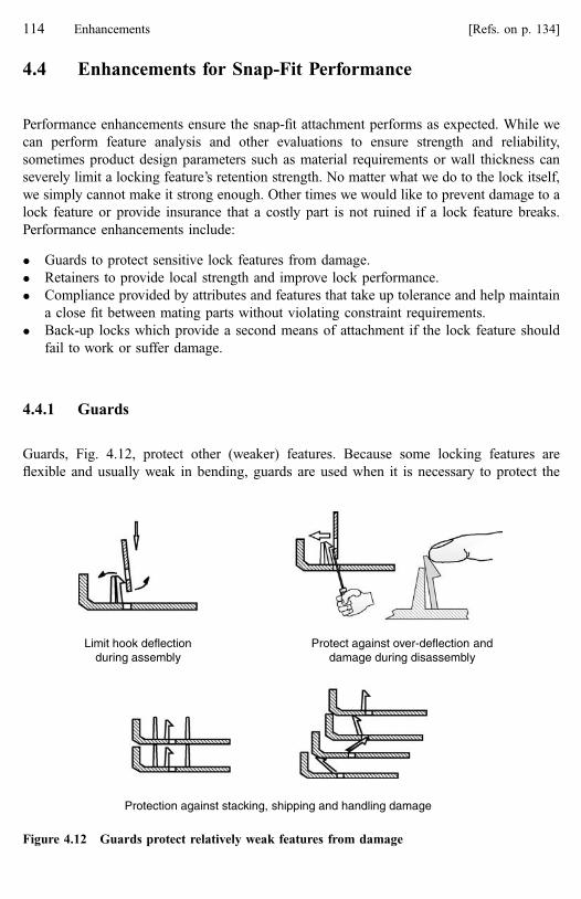
4.4 Enhancements for Snap-Fit Performance
Performance enhancements ensure the snap-fit attachment performs as expected. While we
can perform feature analysis and other evaluations to ensure strength and reliability,
sometimes product design parameters such as material requirements or wall thickness can
severely limit a locking feature’s retention strength. No matter what we do to the lock itself,
we simply cannot make it strong enough. Other times we would like to prevent damage to a
lock feature or provide insurance that a costly part is not ruined if a lock feature breaks.
Performance enhancements include:
� Guards to protect sensitive lock features from damage.
� Retainers to provide local strength and improve lock performance.
� Compliance provided by attributes and features that take up tolerance and help maintain
a close fit between mating parts without violating constraint requirements.
� Back-up locks which provide a second means of attachment if the lock feature should
fail to work or suffer damage.
4.4.1 Guards
Guards, Fig. 4.12, protect other (weaker) features. Because some locking features are
flexible and usually weak in bending, guards are used when it is necessary to protect the
Protection against stacking, shipping and handling damage
Limit hook deflectionduring assembly
Protect against over-deflection anddamage during disassembly
Figure 4.12 Guards protect relatively weak features from damage
114 Enhancements [Refs. on p. 134]

lock. Conditions that create the need for guards should generally be avoided, but design
constraints may force those conditions. Because the cantilever hook type of locking feature
is most likely to require guards, the example shown here involves cantilever hooks. The
principles behind the use of guards, however, apply to any locking feature or other sensitive
part feature. A number of situations may call for guard features.
Snap-fit features (or other part features) may be in exposed locations and susceptible to
possible damage when parts are stacked for shipping and handled before or after shipping.
They may be subjected to short or long term deflections. Guards can provide protection and
prevent permanent set or breakage. For efficient design, the guard function, if needed, should
be built into guides or locators.
When (non-releasing) locks must be manually deflected to release parts, the possibility
of over-deflection exists. When the lock is hidden and a tool must be used instead of a finger,
the chances for damage increase. Because plastic performance is very time dependent, a lock
that survives a very short term deflection during assembly without damage may not survive a
similar deflection of longer duration during much slower manual disassembly. Guards can
limit lock deflection to just that needed for release and prevent permanent damage.
Sometimes during assembly, a hook can be deflected beyond a safe strain level. In a
manner similar to that for preventing over-deflection during disassembly, a guard can limit
hook assembly deflection by effectively increasing the hook’s bending spring rate. The
increased hook stiffness transfers some deflection to the mating part. This will come at a
cost, however, because a higher assembly force is now required to deflect the mating part.
4.4.2 Retainers
Preferred practice is to design the attachment’s strength and retention performance directly
into the locking features. However, design constraints, material requirements or compliance
in the parts themselves may result in an inherently weak lock. Sometimes, locks must resist
high removal forces and this capability cannot be guaranteed through the lock design alone.
Retainers can improve a lock’s retention strength by increasing its bending spring rate, or by
providing positive interference against deflection, Fig. 4.13. It is appropriate to use retainers
for improving both releasing and non-releasing locks. Even non-releasing locks can release
under very high load conditions due to gross distortion of the part or the lock itself. A
retainer can be positioned to prevent that gross distortion.
Lock features mounted on weak, flexible walls will have limited strength. Retainer
enhancements can add local strength within the lock pair.
4.4.3 Compliance
Compliance is the attachment’s ability to accommodate dimensional variation so parts are
easy to assemble while maintaining a close fit with no looseness. Compliance is also
discussed in Chapter 5.
4.4 Enhancements for Snap-Fit Performance 115

Robustness to dimensional variation is designed into the attachment system through
proper constraint and constraint feature selection. Sometimes, however, this is not enough to
ensure a close fit between parts. Compliance within a constraint pair is then used to
supplement the systems performance.
Because they do not use clamp load (like threaded fasteners), a major design requirement
for a snap-fit is that parts fit together tightly, with a line-to-line fit, for functional integrity
and appearance. Another benefit when a line-to-line fit is maintained is that noise (generally
squeaks and rattles) resulting from transient loads is eliminated. One way to get a line-to-line
fit is by specifying very close tolerances on parts, but this can be expensive.
Noise in an interface results from energy inputs that cause parts to separate and snap
back, resonate or rub together. Preventing noise is a matter of holding parts tightly so
separation and relative motion cannot occur under high transient loads or high frequency
vibration conditions. The kinds of load cycles that cause noise in plastic are generally of
very short duration whereas published performance data is usually based on loads applied
A supporting finger prevents thehook end from distorting andreleasing under separation forces
A bridge-likespringincreasesthe hook’sbendingresistance
Assembly Assembly
Locks mayrelease due toweak andflexible wall
A strap behindthe lock addslocal strength.Note the bevelsadded forclearance
Figure 4.13 Retainers provide local strengthening to locks
116 Enhancements [Refs. on p. 134]
over a longer period. Because of the time-dependent behavior of polymers, the strains in the
plastic parts under these loading conditions may sometimes exceed the tested strain limits of
the material for loads of longer duration. In any case, the compliance features must be
designed for long-term effectiveness and resistance to cumulative damage over time. Long-
term plastic creep and degradation of the material’s properties must also be considered.
When considering how to effectively add compliance to the application, know the
significant tolerances and stack-ups in the interface. Whenever possible, design so that
tolerances can be taken up in a non-critical area and direction. Know where potential
looseness or interference may occur due to differences in the mating materials’ coefficients
of thermal expansion. Design so that looseness will not cause noise and interference will not
cause yield to the extent that looseness results.
See the discussion of critical directions and tolerances in Chapter 5. Deciding where to
add compliance depends on critical alignment requirements and interface forces. In general,
compliance is added opposite the fine-tuning enhancements.
Two ways to add compliance in the interface are local yield and elasticity. A third way
involves adding additional pieces called isolators to the system.
4.4.3.1 Compliance through Local Yield
Local yield involves using features within a locator pair to create low levels of interference
(through compressive stress), Fig. 4.14a. The interference results in (local) yield within that
locator pair. While creep to a lower stress may occur over time because of the compressive
stress, as long as no significant additional loads or deflections are applied to cause further
yield, a line-to-line fit will be maintained.
Designing for local yield may conflict with the need for good tactile assembly feedback
and caution is required so feedback quality is not compromised. Local yield means that
resistance to assembly forces will occur over a longer period and involve more than just the
lock features. Treat it as an offset or a zero-shift in the assembly force-deflection signature.
Sometimes you must balance the two requirements, realizing there is not a perfect solution.
Compliance through local yield should occur within a constraint pair. Compliance
between constraint pairs across different locating sites should generally be avoided because
it can violate the rule against over-constraint. However, it is sometimes necessary in
applications where the base part is an opening or a cavity. An example is the solid to opening
application shown in Fig. 4.4. In that application, darts could be added to the land locators
that are visible in the illustration. The darts would act against the land-edge locator pairs on
the hidden sides of the solid.
While plastic yield is possible in tension, bending or compression, the only mode of
yield recommended for yield compliance is compression.
Because local yield requires strength in the features to force the compressive stress, it is
rarely employed with locking features. Most of the time, local yield compliance will be
found on locator features. Methods of obtaining interference through local yield include
darts, crush ribs, and tapered features, Fig. 4.14a.
Darts on pins, lugs and wedges will embed into the edges of other locator features as the
parts are pushed together. Darts, to be effective, should be placed on the harder of the two
plastics in the interface. When the plastics are similar in hardness, a shallower included angle
on the dart can ensure its effectiveness.
4.4 Enhancements for Snap-Fit Performance 117

(b) Getting compliance through elasticity by designing spring features into the system
(a) Getting compliance through local yield
DartsCrush
rib
Crush ribs in a track application
Lug into atapered cutout
Figure 4.14 Compliance helps take up tolerances
118 Enhancements [Refs. on p. 134]

Crush ribs are exactly what the name implies. They are relatively thin ribs that are
literally crushed or bent out of the way by the mating feature. The portion of the rib that
remains then fills the gap between the parts. In the track application, Fig. 4.14a, strategically
placed crush ribs ensure that a bayonet type mount will remain tight in the mating track [4].
Another way to get local yield is by using lugs with tapered cutouts, tapered pins with
holes and tapered wedges with slots, Fig. 4.14a.
4.4.3.2 Compliance through Elasticity
The inherent elasticity of plastic can also be used to establish and maintain a line-to-line fit
between parts. If parts are structurally rigid, special molded-in features acting as springs can
provide elasticity, Fig. 4.14b.
The slight warping that occurs in some parts, particularly panels, as they come out of the
mold may provide sufficient residual elasticity for a close fit after the part is nested and
locked in place against the base part.
Unlike local yield, which is best limited to locators, elasticity can be effectively used
with both locator and lock features. Remember, however, that (most) lock features are weak.
Use caution when taking up compliance in a lock pair.
4.4.3.3 Isolators
As a last resort, because it will add cost to the attachment, isolating materials can be added
to the attachment to force a line-to-line fit. These can take many forms, including adhesive-
backed foam or felt products, soft rubber or felt washers and O-rings. Off-the-shelf O-rings
can be easily slipped over a protrusion feature for a quick fix to a looseness problem. (Ensure
there is no oil on the rings that could react with the plastic material and that the plastic is not
reactive to the O-ring material itself.) Also, ensure that any added materials do not create
excessive stress or strain in lock or locator features.
4.4.4 Back-Up Locks
The last enhancement for performance, a back-up lock, provides a locking alternative in the
event the intended integral lock feature cannot provide reliable locking. Usually they are
simply provisions in the mating and base parts for threaded fasteners, push-in fasteners or
metal clips should the integral lock feature fail.
The cost saving potential of snap-fits often indicates their suitability as the mainstream
attachment design for an application. However, technical and=or business issues may prevent
their serious consideration. Back-up locks can help overcome some of those obstacles.
When appropriate, a back-up lock can be made a part of the business case when evaluating
an application’s attachment alternatives. A significant factor in back-up lock decisions is the
piece cost of the part in question. A back-up lock may not be cost effective on a small
inexpensive part but could be very desirable on a large, complex and expensive one.
In some applications, a conservative approach to the snap-fit is desirable because the
snap-fit may represent a technical ‘‘reach’’. The potential benefits may be substantial but the
risk of committing to a snap-fit may preclude its consideration unless a back-up fastening
4.4 Enhancements for Snap-Fit Performance 119

method can be designed into the interface at the same time. Once the design is proven in
testing and production, the back-up lock can be eliminated. Should the snap-fit prove
unreliable, the back-up lock allows the development program to continue with a reliable
attachment for that application.
While the design itself may not be a technical reach, incomplete data about the service
loads, material properties or other application requirements may add uncertainty to the
design. A back-up lock can allow the snap-fit design to proceed with the confidence that a
reliable attachment is possible if the snap-fit does not work.
The design may be such that the locking features of the snap-fit are susceptible to
bending or breakage during shipping, handling, assembly or disassembly. If the features
cannot be protected by design (see guards) and damage that would render the lock
unworkable is possible, a back-up lock ensures the entire part will not be lost because of
damage to one feature.
If parts are intended for new designs and also expected to be used on existing designs
without provisions for snap-fits, allowing for both methods of attachment accommodates
both applications without creating a second set of parts.
Any fastening method may be a candidate as a back-up to a snap-fit and the design
criteria should be appropriate to the technology. The same reliability considerations must be
applied to the back-up lock as to the original snap-fit.
Back-up locks need not be complex. Providing several clearance holes in a part and pilot
holes, bosses or clearance holes in the mating part may be sufficient. Of course, if the back-
up lock may become the mainstream design for production then all assembly and processing
considerations must be included in the design. If necessary, clearance holes for threaded
fasteners can be skinned over and drilled out if needed. Complementary ribs can be added on
both parts in proper positions to accept and engage spring steel clips as back-up fasteners.
When a back-up lock is specified because of possible damage in disassembly for service
or as a second attachment method on a service part, original assembly issues are no longer
critical. Give consideration instead to the tools and fastening methods required for service by
the customer or service technician. Do not design a back-up lock that requires special
fasteners or special tools.
Rules for back-up locks include:
� Use fasteners identical to other fasteners in the product.
� Use common fasteners that repair facilities are likely to have.
� If high strength is not an issue, and it usually is not in a snap-fit application, design for
hardware store type fasteners readily available to the home mechanic.
� Provide adaptable interfaces that permit several sizes, styles or lengths of screw.
4.5 Enhancements for Snap-Fit Manufacturing
Manufacturing enhancements are techniques that support part and mold development,
manufacturing and part consistency. Many are documented in standard design and
manufacturing practices for injection-molded parts and are already recognized as important
120 Enhancements [Refs. on p. 134]

factors in plastic part design. They fit neatly into the Attachment Level Construct as
enhancements.
These enhancements generally make the part easier to manufacture. Parts that are easier
to make are more likely to be made consistently and correctly. They are more likely to
perform as expected, an important component of reliability. Another benefit is that they are
likely to be less expensive.
Manufacturing enhancements can provide benefits in:
Cost Shape consistency
Appearance Mold development
Reliability Internal stresses
Process cycle time Performance consistency
Fine-tuning for development Adjustments for variation
Detailed plastic part design principles, mold design practices and manufacturing
procedures are well documented in many other books and standards and that information
will not be repeated here. This section is not intended to be a comprehensive guide to the
subject of mold design. The intention is to simply capture this particular aspect of snap-fit
design as an enhancement and present a few of the more basic concepts that relate directly to
snap-fits.
Remember that snap-fit features are subject to the same rules of good mold design as the
other features in an injection-molded part. Many snap-fit features are protrusions from a wall
or surface and they should be designed according to the same rules as protrusions.
Sometimes, a snap-fit designer relies on the part supplier (if another company) or the
experts in their own company to provide the information and design expertise for part
processing. There is nothing wrong with this; one should rely on the experts. However, it
does not hurt to know enough to be able to ask some intelligent questions. You may
occasionally catch something they have overlooked. The part designer is also most familiar
with the requirements of the application and is in the best position to ensure they are
properly considered.
Manufacturing enhancements fall into two groups. Those that improve the part making
process we call process-friendly. Those that allow for relatively easy dimensional changes to
the mold, are fine-tuning enhancements.
4.5.1 Process-Friendly
Process-friendly design is simply following the recommended and preferred plastic part
design practices. Process-friendly parts are robust to the molding process and are likely to be
higher quality, less expensive and more consistent in performance than parts that are not.
The information shown in this section was drawn from a number of publications. It
seems to represent general design knowledge because very similar or identical information
was typically found in multiple documents. Rather than cite numerous publications for each
item presented all the publications are listed at the end of this chapter.
4.5 Enhancements for Snap-Fit Manufacturing 121

The single most important rule is to keep the design simple: the simplest design that will
work is obviously the best, Fig. 4.15a. Simple feature designs mean less costly molds and
greater consistency. When moving parts are required in the mold to make under-cuts and
hidden features, die complexity and cost goes up. Access for molding under-cuts is an ever-
present issue with mold design and snap-fits are no exception. Features that can be produced
without requiring the added complexity of mold features like slides and lifters are always
preferred.
1. Calculate the basic protrusion width (W) from the wall thickness.
2. Add the draft angle to the basic protrusion width.
3. Add a radius (Rp) at the protrusion base.
4. Verify that the material volume at the protrusion base does not exceed about 120% ofthe normal wall volume.
(c) Adjust the protrusion thickness relative to the wall thickness and use a radius at the wall
(b) Round all corners, both internal and external
(a) Use simple shapes and allow for die access and part removal
Use simple shapeswhenever possible Provide die access to form feature undercuts
Rint ≈ T/2 ± 10%
Rp ≈ 0.25 T minimum
Rp ≈ 0.5 T maximum
Rint ≈ 2 mm (typical)
Rext ≈ (Rint + T) ± 10%
Rint
Rext
W
TR2R1
Rp
0.5 T ≤ W ≤ 0.6 T
R1 ≤ R2 ≤ 120% R1
Rules of thumb:
Figure 4.15 Common process-friendly design practices
122 Enhancements [Refs. on p. 134]

(d) Protrusion spacing
Rules of thumb:
H ≤ 5T
D > 15 mm (typical)
D > 3H (minimum)
(e) Allow for draft angles (f) Taper all section changes
Minimum draftangle of 2°.4° ispreferred A 3:1
taper iscommon
(g) No thick sections (h) Allow for a shut-off angle where the die faces meet in shear
Typical thickness is ~ 2 - 4 mm
Minimumshut-off angle
of 5° - 7°
15° ispreferred
D
W
D
H
Figure 4.15 (continued) Common process-friendly design practices
4.5 Enhancements for Snap-Fit Manufacturing 123
Sometimes, a complex feature shape may be required if moving parts in the die are to be
avoided. In that case, consider the costs and advantages of both designs. Also, consider that
analytical tools for predicting lock and locator behavior tend to be less accurate as feature
shapes become more complex.
Specify a radius for all inside and outside corners, Fig. 4.15b. The idea is to avoid all
sharp corners and maintain a constant wall thickness for smooth plastic flow through the
mold. (The melt front does not like surprises.) Corners cause turbulence and are hard to fill.
It is not enough to simply ask for fillets and radii in a general drawing note. Put a dimension
at every site where a fillet or radius is required.
Sharp internal corners also create sites for stress concentrations. When at the base of a
constraint feature, they can cause feature failure. Treat every protrusion feature (hooks, pins,
tabs, lugs, etc.) as a rib and follow the guidelines for rib sections and rib spacing. The idea is
to maintain a relationship between the wall thickness and the protrusion thickness so that
voids or residual stresses at the base of the feature do not occur. Some basic rules are shown
in Fig. 4.15c and Fig. 4.15d. Keep in mind however that these are general rules and simply
provide a good starting point. Specific plastics can have their own requirements.
If a prototype part shows sink marks on the opposite side of the wall from a protrusion,
this is a good indication that voids or residual internal stresses may be present at the base of
the feature. These will weaken the feature and may result in failure.
Include a draft angle. This allows the part to be easily removed from the mold. Start with
the basic feature size then add the angle to each side, Fig. 4.15e.
Avoid thick sections and abrupt section changes for the same reasons you avoid sharp
corners. Another reason is the difficulty of cooling a thick section of plastic. To properly
cool a thick section results in significantly longer cycle times and higher cost, Figs. 4.15f
and g.
Where die faces come together in shear, a shut-off angle is necessary, Fig. 4.15h. This
applies when access for molding hooks or lugs is required, Fig.4.15a.
Gates are the areas where the plastic melt enters the mold cavity and gate style and
location are other aspects of mold design that can have a significant effect on the snap-fit
features. Gates can affect the constraint feature’s location (due to part warping) and the
feature’s strength. Remember that the mold designer is not likely to know the critical areas of
your design and will put the gates at locations they believe are the best sites for mold
fabrication and performance unless you indicate otherwise. Gates should be located:
� Away from flexible features and impact areas.
� So that knit lines will not occur at high stress areas, including living hinges.
� In the heaviest=thickest sections so that flow is to the thinner, smaller areas.
� So flow is across (not parallel to) living hinges.
� So flow is directed toward a vent.
� In non-visible areas.
� So that flow distance to critical features is not excessive.
Gate location can also affect part warpage. Be sure the snap-fit features do not move out
of position due to excessive part warpage. If they do, guide enhancements may be needed to
bring the locks back into proper position for engagement.
124 Enhancements [Refs. on p. 134]

4.5.2 Fine-Tuning
Fine-tuning involves adjusting the mold dimensions to result in correct final part
dimensions. It is necessary because the nature of the molding process is such that first
parts out of the mold will not be perfect. Despite the use of predictive tools and highly
controlled processing techniques, one never knows exactly what the part will be like until
first parts are made. This is particularly true when the snap-fit designer is concerned with
high precision in constraint feature locations and dimensions. Part changes and adjustments
during part development become much easier when allowances are made for fine-tuning
during part design.
Once production begins, long-term wear, variations in raw materials, design changes and
variation in the other part may also require periodic mold adjustments to maintain
attachment quality throughout the part’s production run.
In anticipation of changes, plan for easy mold adjustments at strategic locations. The
purpose is to avoid large-scale (expensive and time-consuming) mold changes. In other
words, make the snap-fit interface ‘‘change-friendly’’.
The first step in adding fine-tuning enhancements is to identify critical alignment and
load carrying requirements and the constraint sites that provide that capability. This should
have already occurred in the design process because you needed to understand the critical
constraint sites to establish constraint and compliance requirements. These sites represent
the areas of the part (thus the mold) where fine-tuning is likely to be needed, Fig. 4.16. Fine-
tuning site selection also affects compliance enhancement locations. Once these critical sites
for fine-tuning are identified, you can decide if metal-safe design or adjustable inserts are
appropriate.
Metal-safe means to fine-tune the part by removing rather than adding metal to the mold.
Obviously, it is much easier to simply grind material away in the mold than to first build up
an area then shape it by grinding metal away. Once the critical sites have been identified,
select initial nominal dimensions and tolerances at or slightly beyond the minimum material
condition, Fig. 4.17. Be careful not to carry the idea of metal-safe design to such an extreme
Compliancefor maintaininga line-to-line fitis establishedat the locator
pairs oppositethe critical
alignment sitesProduct requirement:Gap must be maintained to ± 0.2 mm
Product requirement:These edges must be flush to ± 0.1 mm
Dimensional alignmentis established at thelocator pairs close to thealignment critical sitesand fine-tuning may berequired at these sites
Figure 4.16 Selecting sites for compliance and fine-tuning
4.5 Enhancements for Snap-Fit Manufacturing 125
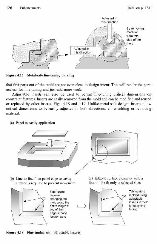
that first parts out of the mold are not even close to design intent. This will render the parts
useless for fine-tuning and just add more work.
Adjustable inserts can also be used to permit fine-tuning critical dimensions on
constraint features. Inserts are easily removed from the mold and can be modified and reused
or replaced by other inserts, Figs. 4.18 and 4.19. Unlike metal-safe design, inserts allow
critical dimensions to be easily adjusted in both directions, either adding or removing
material.
Adjusted inthis direction
Adjusted inthis direction
By removingmaterialfrom thisside of themold
Figure 4.17 Metal-safe fine-tuning on a lug
(a) Panel to cavity application
(b) Line-to-line fit at panel edge to cavity surface is required to prevent movement
(c) Edge-to surface clearance with aline-to-line fit only at selected sites
Fine-tuningrequireschanging themold along theentire length oftwo of theedge-surfacelocator pairs
Tab locatorsmolded usingadjustableinserts in moldfor easy fine-tuning
Figure 4.18 Fine-tuning with adjustable inserts
126 Enhancements [Refs. on p. 134]

Use of adjustable inserts requires designing for local adjustment at the critical constraint
sites. This means you have provided distinct locator features in those areas rather than using
a large part area such as a surface or edge as a natural locator. Fine-tuning a locator feature
or features is much easier than changing the mold for a major part feature.
In the application shown in Fig. 4.18, rather than locate at the edge to surface interface
(natural locators) the fit of the panel to surface is controlled at specific contact sites around
the part perimeters. Fine-tuning adjustments can be made by modifying the inserts at these
sites rather than changing the entire part.
Some rules for fine-tuning are:
� Identify the constraint sites that provide critical positioning or alignment. Make
allowance for fine-tuning at these sites.
� Identify the constraint features that provide the critical strength in the attachment and
determine if fine-tuning will be necessary to adjust performance. Keep in mind that
(a) Initial design leaves some clearance at the hook
(b) Fine-tuning at the edge using an adjustable insert brings the hook face into line-to-linecontact with the mating surface
Place the fine-tuning site as closeas possible to the line-to-line fit
Figure 4.19 Fine-tuning with adjustable inserts
4.5 Enhancements for Snap-Fit Manufacturing 127
simply increasing strength by adding thickness is limited by the process-friendly rules.
Strength can also be increased by adding structural ribs to the features. These ribs can
also be fine-tuned for performance.
� In general, compliance enhancements should be placed at locator pairs that are not fine-
tuning sites.
� Select the initial nominal dimensions and tolerances between those sites so that the
minimum material condition will occur at the tolerance range maximum. This will put
the features slightly undersize. A minimum material condition in the part will result in
maximum material in the mold.
4.6 Summary
This chapter provided detailed descriptions of enhancements and rules for their usage.
Enhancement features are one of the two physical elements of a snap-fit. They may be
distinct physical features of an interface or attributes of other interface features.
Enhancements improve the snap-fit’s robustness to the variables and unknown conditions
that can exist in manufacturing, assembly and usage and are summarized in Table 4.2.
Enhancements are often subtle details in a snap-fit application. They may not be obvious
at first glance. It is suggested that the reader study snap-fit applications to become familiar
with the usage of enhancements. The luggage closure buckle shown in Fig. 4.20 is a readily
available application. If you can compare closures from several manufacturers, you will
begin to see how enhancements can affect the overall quality of the application.
4.6.1 Important Points in Chapter 4
Some enhancements are required in every application; others depend on specific needs of the
application, Table 4.3. When soliciting bids on a snap-fit application, the required
enhancements should be made part of the business case and considered non-negotiable.
They are almost as essential to ensuring a high quality and successful snap-fit as are the
constraint features. When bidding on an application, enhancements may be the attention to
detail that wins you the contract.
During snap-fit development, include enhancements in the initial attachment concepts
and in the first detailed parts made when possible. However, including all enhancements in
the original design or even the first prototype parts is usually not possible or practical. One
must actually assemble and disassemble actual parts to properly assess the need for some
enhancements. Desktop manufacturing methods can provide pre-prototype parts with
enough detail that requirements for visuals, guides and assists can be identified. Other
enhancements (assembly feedback and user-feel, for example) usually require that parts be
made from the design intent plastic using production molds to properly identify and develop
enhancement details to meet product requirements. The need for retainers may not be
apparent until parts undergo physical testing. Table 4.4 shows the steps in the snap-fit
128 Enhancements [Refs. on p. 134]

Table 4.2 Enhancements Summary
Name Why What=How Notes
Ease of assembly
Guidance Ease of assembly Guide—stabilize parts No simultaneous engagement, use locators.Clearance—no interference Usually a feature attribute.Pilot—correct orientation Use locator or guide if possible.
Feedback Indicate good assembly Tactile, audible, visual signals and consistentbehavior
Maximize positive signal and minimize system‘‘noise’’.
May conflict with compliance.
Activation and usage
Visuals Disassembly and operation information Text, arrows, symbols Standard symbols should be used. Training andawareness for customers and service are needed.
Assists Enable disassembly or operation Extensions for fingers, tool access For non-releasing locks. Possible feature damage, visualsor guards may be needed
User feel Perceived quality Tactile, audible Manually activated locks in moveable applications.
Performance and strength
Guards Protect weak or sensitive features Prevent over-deflection, reduce strain Cantilever hooks in particular may need protection.
Retainers Improve retention performance Strengthen or support the lockor stiffen the lock area
Cantilever hooks in particular, may sometimes needretainers.
Compliance Take up tolerances and preventlooseness
Elastic features or local yield May interfere with feedback, use care.
Back-up lock A back-up attaching system Readily available fasteners,adaptable interfaces
For service and repair or as an alternative mainstreamdesign.
Manufacturing
Process-friendly Efficient and consistent manufacturingprocess
Feature design and orientation Follow mold and product design guidelines.
Fine-tuning Development and manufacturingadjustments
Metal-safe design, adjustable inserts,local adjustments
Don’t over-do, select sites carefully. Use only at locatorsites controlling critical dimensions.
4.6
Su
mm
ary1
29

development process where one is most likely to have enough information to add a particular
enhancement. Of course, enhancements may also be added after the fact in response to
product problems.
Some designers seem to feel as if they have somehow failed in their snap-fit design if
they must add various enhancement features. That impression is the result of applying
traditional threaded fastener thinking to snap-fits. Remember that a threaded fastener
attachment represents a ‘‘brute strength’’ approach to fastening. The interface details
required for a good snap-fit design go beyond those necessary for a threaded fastener
attachment. In reality, enhancements belong in every snap-fit and an application without
them will not be the best possible design.
As with the other physical features of snap-fits, locks and locators, the Attachment Level
Construct does not pretend to have invented enhancements. Certain enhancements,
particularly those related to manufacturing and design for assembly, are well documented
elsewhere; others are not. In both cases, however, the construct effectively captures them,
providing a means of describing and classifying them for use. Most of the examples of
enhancements shown here were found on products, often on many different products in
many different variations.
(a) For assembly
All features are beveled or rounded for clearance
Contoured lock assembly faceLocator is also a guide
Wide opening for initial engagement
Good audible and tactile !SNAP!sound when engagement occurs
(b) For disassembly
Access for lock release
Figure 4.20 Enhancements in a luggage closure, a common application
130 Enhancements [Refs. on p. 134]

4.6.2 Design Rules Introduced in Chapter 4
Guides:
� Lock features should never be the first features to make contact with the other part.
� Guides must engage before the operator’s fingers contact the base part.
� Avoid simultaneous engagement of multiple features. One or two guides (or locators)
should engage first to stabilize the mating part to the base part, particularly when the
guides are protruding features engaging into holes or slots.
� A ‘‘tip’’ assembly motion is preferred because it forces initial engagement at one end of
the part followed by rotation to sequentially engage the remaining features.
� Build the guide and pilot functions into existing constraint features whenever possible.
Clearance:
� Specify a taper or a radius on all corners and edges of the parts proper as well as on all
the features.
� Always provide generous clearance for initial engagement.
Table 4.3 Enhancement Requirements
Group Enhancement type Required in
all applications
Required in
some applications
Nice to have
and recommended
Assembly Guidance (Guides)
Guidance (Pilots)
Guidance (Clearance)
Operator feedback
Activation Visuals
Assists
User feel
Performance Guards
Retainers
Compliance
Back-up lock
Manufacturing Process-friendly
Fine-tuning
4.6 Summary 131

Table 4.4 Enhancement Identification and the Development Process
Enhancement Development stage Comments
R C D T
Guidance (Guides) Required. Combine with locators.
Guidance (Pilots) Required if a symmetric part can beimproperly oriented.
Guidance (Clearance) Required. Certain clearance features (lands)may be identified early. Details of clearance,bevels, radii added during design.
Operator feedback Required. Details added in design. Mayrequire testing and evaluation.
Visuals Need may be identified but implementationusually delayed until final parts.
Assists If a non-releasing lock with limited access.
User feel If a user activated lock in moveableapplication.
Guards Need may be identified early, part stacking ormanual deflection for example.
Retainers Sometimes predictable based on applicationconcept (constraint features on thin walls).
Sometimes identified in analysis or test.
Compliance Identify sites at concept development.Execute details during detailed design.
Back-up lock May be early or after testing indicatespotential problem.
Process-friendly Feature orientation decisions during concept.Details and dimensions addedduring design.
Fine-tuning Details and dimensions that support fine-tuning are added during design.
Development stage symbols:
R—When establishing specific application requirements.
C—While developing the attachment concept.
D—Detailed design and analysis.
T—Testing.
—Need for enhancement is likely to be first identified.
—Follow-up or secondary identification.
132 Enhancements [Refs. on p. 134]

Operator feedback:
� Ergonomic Factors—Assembly forces must be within an acceptable range. A
comfortable operator position, normal motions and parts that assemble easily will help
create a work environment in which the operator can be sensitive to tactile feedback.
� Avoid extreme rotational or reaching motions.
� Avoid high forces on fingers, thumbs or hands to install a part.
� Design for top down, forward and natural motions carried out from a comfortable body
position. Avoid awkward reaches or twisting motions and reaches over the head.
� Provide solid pressure points. Weak parts or soft materials may require local
strengthening.
� Design to ensure positive and solid contact between strong locator features.
� A rapid lock return can give a good audible and tactile signal that the lock is engaged.
� A strong ‘‘over-center’’ action as a lock engages will give a feeling that the part is being
pulled into position.
� Consistency in part assembly performance, through process-friendly design, allows the
operator to acquire a feeling for a good attachment.
� Provide highly visible features that are clearly aligned when the assembly is successful.
� Design for go=no-go latching so a part that is not properly locked in place will easily fall
out of position to create an obvious assembly failure.
Assists:
� Indicate operation of the assist with visuals if necessary.
� If tools are used or the lock is not visible, use guards to protect the lock feature against
over deflection during disassembly.
� If tools are required, design the assist so that readily available tools can be used.
Compliance:
� Compliance through local yield should occur within a constraint pair.
� Yield compliance should only involve plastic yield in compression.
Back-up locks:
� Design to use fasteners like those already present in the product.
� Use common fasteners that repair facilities are likely to have.
� If high strength is not an issue, design for hardware store type fasteners readily available
to the home mechanic.
� Provide adaptable interfaces that permit several sizes, styles or lengths of screw.
Process-friendly:
� Refer to the published rules and guidelines for mold design.
� Consider all protrusion features as ribs and follow rules for rib design and spacing.
� Always specify radii and smooth transitions.
� Locate gates away from flexible features and impact areas.
� Locate gates so that knitlines will not occur at high stress areas, including living hinges.
� Locate gates in the heaviest=thickest sections so that flow is to the thinner, smaller areas.
� Locate gates so flow is across (not parallel to) living hinges.
4.6 Summary 133

� Locate gates so flow is directed toward a vent.
� Locate gates in non-visible areas.
� Locate gates so that flow distance to critical features is not excessive.
Fine-tuning:
� Make allowance for fine-tuning at constraint sites providing critical positioning or
alignment.
� Increasing feature strength by adding thickness is limited by the process-friendly rules.
Strength can also be increased by adding structural ribs to the features.
� Use compliance enhancements at locator pairs that are not fine-tuning sites.
� Set nominal dimensions and tolerances at slightly below the minimum material condition
for metal-safe design at selected sites.
� Fine-tuning sites should be as close as possible to the critical dimensions that must be
controlled.
References
1. From a 1994 conversation with Rich Coppa, Senior Principle Engineer, Camera Division of the Polaroid
Corporation, Boston MA.
2. The application redesign in product example #3 was developed by Tom Froling and Tom Nistor.
3. Bonenberger, Paul R., The Role of Enhancement Features in High Quality Integral Attachments (1995),
Technical paper #294 at Society of Plastics Engineers’ Annual Technical Conference ’95, Boston, MA.
4. From a shutter assembly on a Polaroid camera (model unknown).
Bibliography
The following publications all provide highly useful information on plastics and designing
for injection molding. They were used as reference for this chapter.
In alphabetical order:
Beall, Glenn L., Plastic Part Design for Economical Injection Molding, 1998, Libertyville, IL.
Dupont Polymers, Dupont Engineering Polymers—Product Information Guide, Dupont Polymers
Department, Wilmington, Delaware.
GE Plastics, GE Engineering Thermoplastics Injection Molding Processing Guide, 1998, General Electric
Company, Pittsfield, MA.
Hoechst Technical Polymers, Designing With Plastic—The Fundamentals, Design Manual TDM-1, 1996,
Ticona LLC, Summit, NJ. (Formerly Hoechst Celanese Corporation, now a division of Celanese AG.)
Malloy, Robert A., Plastic Part Design for Injection Molding—An Introduction, 1994, Hanser=Gardner
Publications, Inc., Cincinnati, Ohio.
Molders Division of The Society of the Plastics Industry, Inc., Standards and Practices of Plastics Molders—
1998 Edition, Washington DC.
Monsanto Company, Monsanto Plastics Design Manual, 1994, Monsanto Company, St. Louis, MO.
Xerox Corporation, Plastic Design Aid (wallchart), 1987.
134 Enhancements

5 Fundamental Snap-Fit Concepts
Rather than interrupt other topics with a detailed discussion of the concepts of constraint and
decoupling, those subjects are covered in detail here.
Constraint was introduced in Chapter 2 as the most fundamental of the four key
requirement for snap-fits. It was also discussed in Chapter 3 in terms of the application and
use of locators and locks as constraint features.
Decoupling was referred to briefly but has not been discussed at length. Decoupling is
the extent to which a locking feature’s assembly and retention behaviors are independent of
each other. It has important ramifications for understanding lock behavior and improving
lock performance.
5.1 The Importance of Constraint
Conscious or explicit consideration of constraint in attachments is not common practice.
Many designers are accustomed to specifying threaded fasteners and are familiar with design
practices for attachments using threaded fasteners. Threaded attachments achieve constraint
in a rather simple manner: fasteners are added and tightened until the resulting clamp load is
sufficient to prevent relative motion in the joint. Constraint between the joined parts happens
automatically and making explicit decisions about constraint during threaded fastener
attachment design is not necessary. As the reader will learn in Chapter 8, Snap-fit Problem
Diagnosis, improper constraint is a major contributor to problems with snap-fits.
Some design practices for attachments that use adhesives or other methods that do not
rely on clamp load are similar to snap-fit design but not identical. There are special issues
with snap-fits that are not present in any other attachment. Designers must always be aware
that many design principles associated with other attachment methods do not work for snap-
fits.
Most importantly, and unlike threaded fasteners, it is not possible to get tensile stretch in
snap-fit features to create significant clamp load. Getting clamp load through feature bending
is possible, but not extremely efficient and is not recommended. In any case, because plastics
tend to creep under stress, even if some clamp load is designed into a plastic snap-fit, it will
eventually relax and the clamp load will be lost. If the features do not break or yield during
this process, you are left with a line-to-line fit. The art of good snap-fit design is to simply
design that line-to-line fit into the interface at the start. Proper use of constraint makes it
possible to balance the attachment’s need for strength, assemblability and a line-to-line fit
with the realities of part variation and tolerances.

5.1.1 Constraint Review
Recall that the motion of an object in space is described by six translational and six
rotational movements for a total of 12 degrees of motion (DOM). In the case of snap-fits,
this is how the positional relationship of the mating part to the base part is described.
Constraint features are used to restrict motion and systematically remove degrees of motion
from the mating part to base part interface. Some people have an intuitive feeling for
constraint and apply constraint principles automatically when designing a snap-fit. For
others, an understanding of constraint must be developed.
Because constraint features are restraining the mating part to the base part, constraint
(i.e. feature line-of-action) vectors are shown in the figures as acting on the mating part to
prevent its movement. Because we are designing snap-fits for line-to-line fit, the ‘‘force’’
represented by constraint vectors is a potential resistance to external loads applied to the
system. It is not an actual or a constant force exerted by a constraint feature.
5.1.2 Constraint Principles
When considering constraint, it is important to differentiate between perfect constraint and
proper constraint. For learning purposes, we will first introduce and explain constraint in
terms of perfect constraint. Under perfect constraint conditions, forces between all constraint
pairs are statically determinate. In other words, we can calculate them using principles of
mechanics and statics without worrying about part spring rates or redundant forces. For most
applications, achieving perfect constraint while avoiding possible looseness between the
parts would require zero tolerances. Zero tolerance is, of course, an expensive and generally
impractical situation. Complex part geometry and part compliance also make perfect
constraint (easy to get with the rectangular solid used in the following example) rather
impractical in reality.
5.1.2.1 Perfect Constraint
Perfect constraint implies perfect or 100% attachment efficiency where part movement is
prevented using the minimum number of restraint points and the interface system is
statically determinate. An understanding of some of the characteristics of perfect constraint
will provide a basis for the more practical concept of proper constraint.
Recall that a plane is defined by three points and a line by two and that a system of three,
two and one point(s) can perfectly locate an object. An object in space (the mating part), Fig.
5.1a can be prevented from moving in one DOM by constraining it at three points (a plane)
as shown in Fig 5.1b. Next, adding two points to one side of the object will prevent
movement in another DOM, Fig 5.1c. A single point on another side of the object will
prevent movement in a third DOM, Fig 5.1d. The object’s position is now accurately
determined by the plane, the line and the single point. This is acceptable as long as no forces
act on the object to move it out of this position. In products, forces are part of the design
reality so more than just well-defined positioning is required to constrain the object.
136 Fundamental Snap-Fit Concepts [Refs. on p. 161]

(c) Second, two points define a line (d) Third, a single point completesthe positioning
(a) A rectangular object is to bepositioned to another object
(e) Restraining forces hold the part inposition
(f) Restraining forces can becomposed into one resultant force
(b) First, three points define a plane
FR
(g) In a snap-fit, line-to-linecontact with featuresholds the part inposition
Figure 5.1 Perfect constraint
5.1 The Importance of Constraint 137

Additional restraint is needed to hold the object against the plane, line and point. This is
done by adding three forces, each one acting to hold the object against one of the three
positioning sites as shown in Fig. 5.1e. These three additional forces accomplish a number
of important things as they hold the object against the established location points: (1) they
prevent translation movement away from the established points and (2) they remove all of
the rotational movements from the system. The remaining nine DOM are removed (three in
translation and six in rotation) and the object is now constrained in a total of 12 degrees of
motion. These three restraining forces can be shown as one resultant force FR as shown in
Fig. 5.1f. This force must be strong enough to hold the object against any outside forces
seeking to move it out of position. A bolt passing through the part along the FR line-of-
action and tightened to create clamp load would do this. In the case of a snap-fit, however,
we will not rely on clamp load. Features that will not exert clamp load, but will resist
movement can be strategically placed so they just touch the object (a line-to-line fit), Fig
5.1g. This represents a perfectly constrained snap-fit. (As with the forces above, the
restraining effect of the three features could also be represented as a resultant.)
Recall the discussion in Chapter 3 about the desirability of spacing constraint features as
far apart as possible for dimensional robustness and strength. That design rule can be further
elaborated using this example of perfect constraint. To maximize mechanical advantage for
strength and minimize dimensional sensitivity in each direction, the three planar constraint
points should be arrayed against the largest area of the object, the two linear constraint
points are arranged against the next largest area of the object and the single point against the
third largest area. Compare the inherent stability of the arrangement in Fig. 5.2a to the
instability of the arrangement in Fig. 5.2b. While the latter is technically correct with respect
to perfect constraint, it obviously lacks the mechanical advantage against outside forces and
the dimensional robustness of the former. What if the object is a cube and all sides are equal
in size? Some judgement is required depending on the application requirements but, as a
rule, the three-point constraint site would be selected to resist the highest forces or to control
the most critical dimensions.
(a) Perfectly constrained, robust forlocating and stable againstoutside forces
(b) Perfectly constrained but robustnessand stability are poor
Figure 5.2 Part stability, dimensional robustness and constraint feature strength is optimizedby proper feature placement with respect to part shape
138 Fundamental Snap-Fit Concepts [Refs. on p. 161]
The spacing principles for maximizing the object’s stability with respect to the initial
constraint points are also true for the restraining points that are added to hold the object
against the constraint points.
Note that the ‘‘theoretical’’ three-point site may, in reality, not look like three points at all
and it is not necessarily the first site of contact between the mating and base parts nor is it
necessarily the most constraining locator site.
5.1.2.2 Proper Constraint
Perfect constraint is an ideal. In reality, snap-fit design is a compromise between perfect
constraint and the realities of a given application. When we have designed according to the
constraint guidelines, we can say the snap-fit is properly constrained, meaning that within the
limits of tolerances and with the help of local compliance, the attachment is a reasonable
approximation of perfect constraint. A realistic explanation of proper constraint is that it
exists when there are no gross violations of the rules defining improper constraint. It is the
absence of under-constraint and the minimization of over-constraint conditions.
When parts are properly constrained, they will have these desirable characteristics:
� Can be assembled without forcing parts together.
� Normal or loose tolerances between constraint features in the interface are possible.
� Static analysis of forces on the constraint features is possible.
� No residual forces exist between constraint pairs after assembly.
5.1.2.3 Proper Constraint in Less than 12 DOM
We have commonly used a fixed application as an example of proper constraint and required
that the mating part be restrained in exactly 12 degrees-of-motion. The reader must not
forget that when the attachment’s action is moveable (either controlled or free), proper
constraint may exist with less than 12 DOM.
5.1.2.4 Under-Constraint
In a fixed application, if parts are constrained in less than 12 DOM, they are under-
constrained. Under-constraint can cause the following problems:
� Lock feature damage because locks are improperly loaded.
� Parts improperly aligned or loose because the constraint features cannot effectively
prevent relative movement.
� Parts falling off when damaged constraint features release or break.
A common under-constraint mistake is designing so that a lock must carry forces in an
improper direction. Locks are weak and should be used only to resist movement in the
separation direction. Locator features must be used to prevent all other movements.
A second common under-constraint mistake is failure to place locators for maximum
mechanical advantage. This relates to the discussion of stability and Fig. 5.2. Because of
highly complex part shapes this becomes a highly subjective area. A locator arrangement
may not be technically under-constrained but it may be less stable than it could be. The
difference between proper constraint and over or under-constraint is often a matter of degree,
not absolutes.
5.1 The Importance of Constraint 139

The most important thing to know about under-constraint is that it must be fixed.
5.1.2.5 Over-Constraint
When constraint features are ‘‘fighting’’ each other, they are over-constrained. Over-
constraint can cause these problems:
� Difficult assembly. When locator pairs must be forced together, high assembly forces
result and immediate damage to constraint features is possible.
� Increased feature stress. Assembly interference between constraint pairs can create
internal residual forces. Short or long-term feature damage and failure are possible.
� Part buckling and temperature distortion as joined parts of unlike materials expand and
contract at different rates. This is unsightly and may also result in long-term feature
damage and failure.
A common mistake is to try fixing an over-constrained design by specifying extremely
close tolerances. This will increases the cost of the parts and, while it may eliminate difficult
assembly or prevent feature damage during assembly, it cannot fix the thermal
expansion=contraction problem. Another common mistake is to confuse over-constraint
with higher strength in the attachment.
There are two kinds of over-constraint violations: features in opposition and redundant
features. Features in opposition is the more serious of the two.
a. Over-Constraint Due to Redundant Features
Sometimes, the designer feels compelled to increase strength by adding additional constraint
pairs to resist a force. When two or more co-linear lines-of-action are resisting the same
translational force, those constraint pairs are redundant in that direction, Fig. 5.3a. In other
words, one of the constraint pairs could be removed or changed to eliminate a redundant
line-of-action without changing the system’s overall constraint condition. That is exactly
what you should do. Determine which constraint pair is least effective or more expensive to
mold and eliminate it or modify it. Design all the necessary strength into the remaining
constraint pair, Fig. 5.3b.
Redundancy in constraint leads to extra cost in the parts because it involves extra
constraint pairs and it requires closer tolerances to ensure simultaneous contact of the
redundant pairs. Most of the time, however, over-constraint due to redundant features is not
serious in terms of attachment performance. With redundant features, we can think of one
constraint pair as helping the other (even if that help is unwanted). This is not the case with
opposing features.
b. Over-Constraint Due to Features in Opposition
Opposition occurs when two constraint pairs have co-linear lines-of-action that are acting in
opposite directions, Fig. 5.4a. Because they have opposing strength vectors, the constraint
pairs will fight each other and the potential for damage is high. Unless the tolerances
between these pairs are held quite close (on both parts), the chances are good that in most
assemblies, there will either be some initial looseness along that axis or the parts will require
140 Fundamental Snap-Fit Concepts [Refs. on p. 161]

additional force to engage because of interference between the pairs. The resulting strain and
residual stress can cause the features to relax and loosen over time.
Even if one is willing to pay the price for very close tolerances to prevent looseness or
strain between the pairs, Fig. 5.4b, the attachment will not be robust to thermal expansion or
contraction along that axis, Fig. 5.4c. If the parts are made of similar materials, the thermal
effects may be minimal. However, some plastics can have quite different thermal expansion
rates depending on fiber alignment or flow characteristics so having identical materials may
be no guarantee against problems. If thermal expansion or contraction is an issue, and
features must oppose each other, try to place them as close to each other as possible to
minimize the actual size differential when expansion and contraction occurs.
The best fix for features in opposition is to replace or redesign the problem constraint
pairs so that motion in both of the directions along the axis in question is resisted at only one
of the pairs, Fig. 5.5a. The second choice is to add compliance enhancements at one of the
problem sites, Fig. 5.5b. However, if forces are resisted or critical dimensions are controlled
by a constraint pair, adding compliance at that site may not be possible.
5.1.2.6 General Constraint Rules
Most of the design rules related to constraint can be found in Chapter 3. Only a few pertinent
constraint rules are repeated here as reminders for the constraint worksheet discussion that
follows.
(a) Solid to surface applicationOne of these two locator pairs
(b) Redundantconstrainteliminated
Remove one constraint pair and makethe other one stronger
F
is redundant
FF
Figure 5.3 Over-constraint due to feature redundancy
5.1 The Importance of Constraint 141
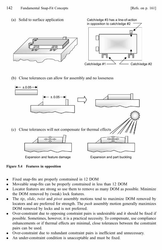
� Fixed snap-fits are properly constrained in 12 DOM
� Moveable snap-fits can be properly constrained in less than 12 DOM
� Locator features are strong so use them to remove as many DOM as possible. Minimize
the DOM removed by (weak) lock features.
� The tip, slide, twist and pivot assembly motions tend to maximize DOM removed by
locators and are preferred for strength. The push assembly motion generally maximizes
DOM removed by locks and is not preferred.
� Over-constraint due to opposing constraint pairs is undesirable and it should be fixed if
possible. Sometimes, however, it is a practical necessity. To compensate, use compliance
enhancements or if thermal effects are minimal, close tolerances between the constraint
pairs can be used.
� Over-constraint due to redundant constraint pairs is inefficient and unnecessary.
� An under-constraint condition is unacceptable and must be fixed.
Figure 5.4 Features in opposition
142 Fundamental Snap-Fit Concepts [Refs. on p. 161]
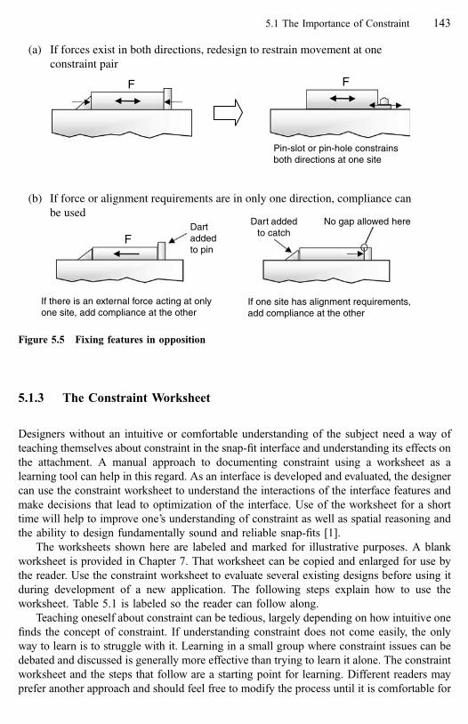
5.1.3 The Constraint Worksheet
Designers without an intuitive or comfortable understanding of the subject need a way of
teaching themselves about constraint in the snap-fit interface and understanding its effects on
the attachment. A manual approach to documenting constraint using a worksheet as a
learning tool can help in this regard. As an interface is developed and evaluated, the designer
can use the constraint worksheet to understand the interactions of the interface features and
make decisions that lead to optimization of the interface. Use of the worksheet for a short
time will help to improve one’s understanding of constraint as well as spatial reasoning and
the ability to design fundamentally sound and reliable snap-fits [1].
The worksheets shown here are labeled and marked for illustrative purposes. A blank
worksheet is provided in Chapter 7. That worksheet can be copied and enlarged for use by
the reader. Use the constraint worksheet to evaluate several existing designs before using it
during development of a new application. The following steps explain how to use the
worksheet. Table 5.1 is labeled so the reader can follow along.
Teaching oneself about constraint can be tedious, largely depending on how intuitive one
finds the concept of constraint. If understanding constraint does not come easily, the only
way to learn is to struggle with it. Learning in a small group where constraint issues can be
debated and discussed is generally more effective than trying to learn it alone. The constraint
worksheet and the steps that follow are a starting point for learning. Different readers may
prefer another approach and should feel free to modify the process until it is comfortable for
(b) If force or alignment requirements are in only one direction, compliance canbe used
If there is an external force acting at onlyone site, add compliance at the other
F
No gap allowed here
If one site has alignment requirements,add compliance at the other
Dart addedto catch
Dartaddedto pin
(a) If forces exist in both directions, redesign to restrain movement at oneconstraint pair
F F
Pin-slot or pin-hole constrainsboth directions at one site
Figure 5.5 Fixing features in opposition
5.1 The Importance of Constraint 143

Table 5.1 Worksheet for Tracking Constraint in the Attachment1
44
Fu
nd
amen
talS
nap
-Fit
Co
ncep
ts[R
efs.o
np
.1
61
]

them. The important result is that the reader understands constraint and can recognize
constraint violations in a snap-fit attachment.
1. Recalling the discussion of perfect constraint and part stability, identify desirable
directions for planar and linear constraint from the standpoint of part geometry. While it
is not always possible to place constraint features at the best or most effective points, it is
important to avoid putting them at the least effective points. On the translation side, this
involves marking the two more desirable axes for three point constraint and the two more
desirable axes for two point constraint. (Circle or highlight the appropriate columns). On
the rotation side of the worksheet, the possible directions for rotational constraint should
also be identified. These identifications may help when choosing between constraint
alternatives later in the process.
� The distance between constraint pairs (with parallel strength vectors) affects both
mechanical advantage against forces and dimensional sensitivity.
� Remember, as these constraint pairs are moved farther apart, their effectiveness
increases.
2. Identify all the force effects that must considered when establishing interface
requirements. As a rule these will only be translational effects so the rotation side of
the worksheet is not used. The user is free to select any sign convention they choose, but
in general, the sign convention should be based on restraint of the mating part. Force
effects may include any or all of the following:
� All forces in the interface due to significant load inputs to the application.
� Engage direction and assembly force.
� Separation force.
3. Identify all the bi-directional effects to be considered when establishing interface
requirements. Like forces these can generally be expressed as translational effects so the
rotation side of the worksheet is not used. These are effects that, by definition, will have
consequences in both directions along a given axis. They include:
� Thermal expansion=contraction.
� Alignment requirements.
� Part compliance.
4. List all the constraint pairs. They can be listed in any order, but the preferred and easiest
order to work with is:
� First list all the locator pairs that establish the interface plane. This is the three-point
or planar orientation from the perfect constraint example.
� Next list the locator pairs that establish linear (two-point) restraint.
� Next list the locator pairs that establish single point restraint.
� Finally, list the lock pairs.
� Label all natural locators with an ‘N’ as a reminder that they may require special
attention if they are to be used as fine-tuning or compliance sites.
5. Identify the contribution each constraint pair makes to removing translational degrees of
motion. Work across the top of the worksheet using the six columns of translation. The
reader may wish to experiment with two ways to do this and choose the one that works
best for them: (1) Constraint pairs are considered one at a time and all DOM removed by
5.1 The Importance of Constraint 145

that pair are identified or (2) each DOM is considered and the contribution of each
constraint pair (if any) to that DOM is identified.
� Use fractions to indicate the estimated contribution of pairs acting in parallel and
having the same sense. It is convenient and generally accurate to assume equivalent
strength and stiffness, thus equivalent contribution. If, for example, a panel is held
in place by eight lock pairs acting in parallel, each pair would receive a value of 18
in the appropriate cell.
� Check for translational under or over-constraint by studying the entries in the
columns. Columns with a total less than one are under-constrained. Columns with a
total of one are properly constrained. Columns with a total greater than one may be
over-constrained; check the constraint pairs against the rules for proper constraint.
� If an under-constraint condition exists, fix it and adjust the worksheet accordingly.
� If over-constraint due to constraint pair redundancy exists, fix it by removing the
least efficient pair (for mechanical advantage and dimensional robustness) and
adjust the worksheet accordingly.
� If over-constraint due to constraint pair opposition exists, fix it if possible and
adjust the worksheet accordingly, or record the condition for later review. Note the
need for feature compliance along that axis.
� One way to fix over-constraint due to opposition is by removing both directions of
movement within one constraint pair (most preferred solution). Another is by
providing feature compliance at one of the constraint sites.
� Where compliance cannot be used or will not be effective, close tolerances between
the opposing constraint pairs will be necessary, but this is the least preferred
solution. Evaluate the effects of relative thermal expansion=contraction of the parts
and the possibility of warpage or damage to features.
� Identify the primary constraint pair based on the alignment and/or strength
requirements of the application. Plan to use this pair as the datum for locating all
other constraint features in the interface.
6. Identify all translational directions and the corresponding constraint pairs that:
� Require high strength to resist interface forces. Mark them with an ‘F’.
� Require positional accuracy to satisfy alignment requirements. Mark them with an
‘A’.
� If strength or alignment requirements are identified in both directions along the
same axis, over-constraint in opposition should be avoided along that axis because
it cannot be fixed using compliance. If over-constraint in opposition was noted in
Step 5, it must be fixed.
7. Identify all translational directions and corresponding constraint pairs where feature
compliance can be added. Mark them with a ‘C’.
� While these may be at the same constraint pair, they must not be in a column
marked with an ‘F’ or an ‘A’. Compliance sites should not carry forces or provide
critical alignment.
8. Identify translational directions and corresponding constraint pairs where expansion and
contraction due to thermal effects may occur. Mark them with a ‘T’.
� In these directions, over-constraint in opposition should be avoided if possible.
Otherwise, compliance in one of those directions will be required. Mark with a ‘C’.
146 Fundamental Snap-Fit Concepts [Refs. on p. 161]

9. Identify sites where fine-tuning enablers may be used. Mark them with an ‘E’. These
must include sites and directions marked with an ‘F’ or an ‘A’.
� There should be fine-tuning sites in each of the three translational directions, but
not in opposing directions. For example, combinations like (þx; þy; �z) or
(�x; þy; �z) are OK. A combination like (þx; �x; þy; þz) is not OK.
� Fine-tuning sites should control all critical alignment directions.
10. Identify directions in which part compliance is an issue. Note that this is not the same as
feature compliance.
� Highly compliant parts (soft or flexible parts like panels) may require multiple
constraint pairs (acting in parallel) to remove all possible flexure. Part compliance is
often an issue in parts with the panel basic shape.
� Verify these constraint pairs are properly spaced to ensure against part flexure.
� Adding stiffening features such as ribs to increase part stiffness is often desirable.
11. Identify the contribution each constraint pair makes to removing rotational degrees of
motion. Work across the top of the worksheet using the six columns of rotation.
� Rotation is removed through constraint pairs acting as couples. A single constraint
pair of sufficient length can also act as a couple; a very long wedge to slot is an
example.
� Use fractions to indicate the estimated contribution of each pair. Assume equivalent
strength and stiffness.
� Note that, similar to the effect described in #4 above, each couple involves strength
vectors in parallel, but as a couple, they will be acting in opposite directions.
� As with constraint pairs acting in parallel to prevent translational movement,
effectiveness in strength and dimensional stability increases as the distance between
the constraint pairs increases.
� Check to verify there is no over or under-constraint in rotation. If there is, fix it and
adjust the worksheet. Verify you have not changed any translational constraint
conditions.
As the reader will quickly discover in trying to actually evaluate constraint and the
feature interactions, it is very much an iterative procedure. Do not expect to experience a
rigorous thought process that will lead to a final answer in just one pass through the
evaluation process.
Table 5.2 shows how the worksheet could be filled out for the perfect constraint example
introduced earlier in the chapter with an external force and a location requirement added as
shown in Fig. 5.6. Table 5.3 shows how the worksheet could be filled out for the simple but
more realistic application in Fig. 5.7. This application is a slight variation of the switch
application shown in Fig. 4.4. The Chapter 4 application is over-constrained in rotation
around the z-axis. The reader might want to evaluate that application using the worksheet to
see how the rotational over-constraint is exposed. Again, have some parts (i.e. ‘‘models’’) in
hand to help visualize part behaviors if you intend to work through these examples using the
worksheet.
5.1 The Importance of Constraint 147

noitoMfoseergeDnoitatoRnoitalsnarTstnemeriuqeRecafretnI
+x −x +y −y +z −z +x −x +y −y +z −z
)sixax()sixax()sixay()sixay(sexaetairporppayfitnedI ,ytilibatstrapgnitamrof
noitatordnanoitalsnart)sixaz()sixaz(
FM ssamtrapdnasnoitareleccamorfgnitluser
FF sdaollanoitcnufmorfgnitluser FF
FN sdaollacipytamorfgnitluser
F(ecroFylbmessA&)DE(noitceriDegagnE A)
lanoitcerid-inUstceffe
F(ecroFnoitarapeS S)
noitcartnoc/noisnapxelamrehT
snoitceridtnemngilAlanoitcerid-iBstceffe ecnailpmoctraP
)N(ecafrusot)N(ecafrus)a( 2/12/12/12/11
2/12/11llawot)N(egde)b(
)tnemngilaedivorptsum(hctacot)N(egde)c( 1
)N(egdeotrotacol)d( 1)ecrofyrractsum( 2/12/1
)ecnailpmocedivorptsum()N(egdeotrotacol)e( 1
)N(ecafrusotkcol)f( 2/12/12/12/11
tniartsnoCsriap
111111111111slatot
tnemngilatrap-ot-traP X AA *XAsetisecnailpmoC X
X
A A *XAevloseRlanoitcerid-ib
stnemeriuqer setisgninut-eniF A A *XA
dnaecnailpmocrofsetistceleS** sexazdnayehtgnolagninut-enif .seciohcelbaliavaehtmorf
raeniL ranalP
elbacilppatoN
elbaliavatonrotluciffid=X**elbaliava=A
rassecen= erro q deriu
htoberehwtluciffiD*.srotacollarutaneraserutaef
pagoN
y
Table 5.2 Example of Using The Worksheet—Perfectly Constrained Object Shown in Fig. 5.6
148
Fundam
ental
Snap
-Fit
Concep
ts[R
efs.on
p.
161]

Table 5.3 Example of Using The Worksheet—Simple Part Application Shown in Fig. 5.75
.1T
he
Imp
ortan
ceo
fC
on
straint
14
9

+x
+z
-z-y
+y
-x
Close fit isrequired at
this interface
F-y
External force is acting on themating part in the -y direction
a
b
c de
f
Figure 5.6 A ‘‘perfectly’’ constrained snap-fit with some requirements illustrated for theconstraint worksheet example in Table 5.2
Surface
+x
+z
-z-y
+y
-x
Pilot
Edge
Surface6 Lands
2 Locks
F-z
Consistent gap isrequired aroundperimeter whenassembled
Visible surfaces mustbe flush whenassembled
a
c
d e
f
b
g
h
i+x
+y
-y
-xLocator pair
identification
Figure 5.7 A solid to opening application illustrated for the constraint worksheet example inTable 5.3
150 Fundamental Snap-Fit Concepts [Refs. on p. 161]
5.1.4 Additional Comments on Constraint
Remember that a blank copy of the constraint worksheet is included in Chapter 7.
A field that makes extensive use of constraint principles is part fixturing. When fixtures
are developed to hold and locate parts for machining or for dimensional checking, proper
constraint is essential.
Most of the constraint principles expressed in this section as well as in Chapters 2 and 3
in the form of qualitative design rules also lend themselves to expression in mathematical
terms. Tools for optimizing a snap-fit interface in terms of constraint, strength, compliance
and tolerances can and should be developed [2].
5.2 Lock Decoupling
Lock decoupling is the degree to which a lock’s retention behavior is independent of its
assembly behavior. Understanding decoupling and the additional lock design options it
provides will help the designer improve lock designs and resolve lock performance
problems. This section describes lock feature decoupling in detail using the common
cantilever hook as an example. See the discussion of ‘‘lock efficiency’’ in Section 3.3.4.3.
5.2.1 The Lock Feature Paradox
By their nature, locking features present a design paradox. They should be easy to assemble,
i.e. weak. (Unless automatic or robotic assembly is planned, in which case assembly force
levels may be less important.) But locks must also be strong to resist breakage or unintended
separation. This conflict between weak and strong performance requirements can sometimes
force design compromises that don’t adequately satisfy either requirement. A solution to this
dilemma is made possible by decoupling (separating) the lock’s assembly performance from
its retention=separation performance.
5.2.2 Decoupling Examples
The concept of decoupling isn’t difficult to understand and it can be a powerful tool for
solving design problems. Decoupling is best introduced with a few examples.
Imagine buying a ladder that is the correct length for climbing to the roof of a house.
Later you decide to wash the windows of the house, but the ladder is too long for that job.
You must move the ladder’s base far away from the house to get the ladder’s end down to
window level. With the base so far away, you can’t climb the ladder without it sliding down
5.2 Lock Decoupling 151
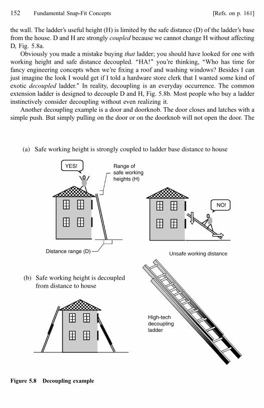
the wall. The ladder’s useful height (H) is limited by the safe distance (D) of the ladder’s base
from the house. D and H are strongly coupled because we cannot change H without affecting
D, Fig. 5.8a.
Obviously you made a mistake buying that ladder; you should have looked for one with
working height and safe distance decoupled. ‘‘HA!’’ you’re thinking, ‘‘Who has time for
fancy engineering concepts when we’re fixing a roof and washing windows? Besides I can
just imagine the look I would get if I told a hardware store clerk that I wanted some kind of
exotic decoupled ladder.’’ In reality, decoupling is an everyday occurrence. The common
extension ladder is designed to decouple D and H, Fig. 5.8b. Most people who buy a ladder
instinctively consider decoupling without even realizing it.
Another decoupling example is a door and doorknob. The door closes and latches with a
simple push. But simply pulling on the door or on the doorknob will not open the door. The
Distance range (D)
YES! Range ofsafe workingheights (H)
(a) Safe working height is strongly coupled to ladder base distance to house(a) Safe working height is strongly coupled to ladder base distance to house
NO!
(b) Safe working height is decoupledfrom distance to house
(b) Safe working height is decoupledfrom distance to house
High-techdecouplingladder
Unsafe working distance
Figure 5.8 Decoupling example
152 Fundamental Snap-Fit Concepts [Refs. on p. 161]

doorknob must be turned to release the latch. The door’s latching and retention
characteristics are decoupled: a push assembly motion and a rotational release motion.
5.2.3 Levels of Decoupling
There are a number of ways that snap-fit locks can be decoupled and they can be broken
down into four ‘‘levels’’. The levels are defined according to how the decoupled assembly
and retention behaviors are analyzed. The levels can also be ranked by effectiveness. This is
important because the more effective the decoupling, the stronger we can make the lock in
retention relative to the assembly force.
Because the cantilever hook is most sensitive to the linkage between assembly and
retention, we will use it to explain decoupling. In a typical cantilever hook (beam and catch)
we find that assembly behavior is affected by beam bending, friction, catch height and the
insertion face angle. In the same hook, retention behavior is affected by beam bending,
friction, catch height and the retention face angle. Thus, both assembly and retention are
directly related to beam bending, friction and catch height. The insertion face angle,
however, only affects assembly and the retention face angle only affects retention.
In the common cantilever hook, any changes made to the beam will affect both assembly
and retention. Making the beam thicker for more strength also increases the strain at its base
during assembly deflection and increases the required force for assembly, making it harder to
assemble. If, on the other hand, the beam is made thin for easy assembly, it becomes weak.
We can see these relations in the basic calculations for assembly force (FA) and retention
force (FR).
5.2.3.1 No Decoupling (Level 0)
There is no decoupling in the hook shown in Fig. 5.9. Assembly and retention behavior are
virtually identical because:
� The calculations (bending) used to analyze assembly and retention are identical because
the hook behavior is the same: beam bending.
The effective insertion angle(α + ∆α) is similar to theeffective retention angle
αβ
Maximum assembly force is roughly equal to themaximum retention strength
Figure 5.9 A cantilever hook with no decoupling (Level 0)
5.2 Lock Decoupling 153

� The same variable (angle) is used in the calculations, the only difference being that the
insertion face angle (a) is used in the assembly calculation and the retention face angle
(b) is used in the retention strength calculation.
� The variables (a and b) have the same values: (a ¼ b).
(For sake of discussion, we will ignore the relatively small change in the moment arm of
the deflection force as it moves over the insertion and retention faces of the catch. We will
also ignore the change in the face angles as the beam deflects.)
5.2.3.2 Level 1 Decoupling
For the hook shown in Fig. 5.10, the only independent variables we have to work with to
adjust assembly and retention behavior are the insertion and retention faces. By making the
insertion face angle (a) low, we can get lower assembly forces but no matter what we do to
the insertion angle, assembly force reduction will ultimately be limited by the bending
strength of the beam. The same is true for retention behavior. We can improve retention by
increasing the retention face angle (b) but again, we are limited by the beam’s bending
behavior.
We could also try to do something with friction on the insertion and retention faces but
we are still limited by the beam’s behavior. Thus, for the common cantilever hook, assembly
and retention behavior ultimately depend on the bending behavior of the beam. The lock in
Fig. 5.10 is partially (but rather ineffectively) decoupled at the insertion and retention faces.
In conclusion, we can point out that this style of cantilever hook is a relatively poor
performer with respect to assembly and retention decoupling and it cannot be made any
(a) Adjusting the retention face angle to increase retention force
The retention angle is muchgreater than the insertionangle
αβ
The retention angle isgreater than the insertionangle
αβ
(b) Adjusting the insertion face to face angle to decrease insertion force
The insertion angle is madeas low as practicallypossible
αβ
Typical decoupling on a hookat minimum α and β at 90o
αβ
Maximum decoupling atminimum α and β greaterthan 90o
αβ
Figure 5.10 Variations of Level 1 decoupling in a cantilever hook
154 Fundamental Snap-Fit Concepts [Refs. on p. 161]

better. This is Level 1 decoupling and it is the lowest and least effective level of decoupling.
It is also the easiest and the most common. The degree of Level 1 decoupling will determine
whether the lock is releasing or non-releasing with the retention face angle being the
determining factor.
5.2.3.3 Level 2 Decoupling
A significant increase in decoupling effectiveness occurs when we move to Level 2
decoupling as illustrated by the side-action hooks in Fig. 5.11. Simply turning the retention
mechanism 90� causes major changes in the behavior of the hook.
The equation for bending force (FP) in a cantilever beam is:
FP ¼ wt2Ee6L
ð5:1Þ
Where: w is beam width; t is beam thickness; e is strain; L is beam length; E is the material’s
modulus of elasticity.
In this equation, we see that FP is directly proportional to beam width (w) and to beam
thickness (t) squared. For the beam shown in Fig. 5.12a, the cross-section is shown with
measurements t ¼ 1 and w ¼ 5. For determining assembly behavior, we would use these
values in the calculation for assembly force and the value of the expression (wt2) is
(5 � 12 ¼ 5).
For retention strength, however, the variables change, Fig. 5.12b. The dimension that was
previously beam width is now beam thickness (t ¼ 5) and the dimension that was thickness
is now width (w ¼ 1). For these new values the value of the expression (wt2) is
(1 � 52 ¼ 25Þ: By this calculation, the retention strength of this side action hook could be as
much as 5 times the strength of a similar hook with Level 1 decoupling. (Beam distortion is
possible and the actual effect may not be as high as 5�, but the improvement is still
significant.) The only change has been to turn the catch sideways.
Level 2 decoupling occurs when different variables are used in the equations. In the side-
action hook, turning the catch 90� on the beam causes the beam width (w) and thickness (t)
variables to change in the equations. However, the same (bending) equations are used, and
they are applied to the same feature (the beam). Level 2 locks may be releasing or non-
releasing.
“Side-action” hooks
Insertion face
Retention face
Figure 5.11 Level 2 decoupling. On a cantilever hook, turning the beam 90� relative to theretention feature can make a significant difference in performance
5.2 Lock Decoupling 155

5.2.3.4 Level 3 Decoupling
Level 3 decoupling occurs when different assembly and retention behaviors within the same
feature require different equations for evaluation. This gives even greater independence
between the assembly and retention behaviors, thus increasing the designer’s control over
each of them. Level 3 decoupling occurs naturally in the trap lock, Fig. 5.13a, where
assembly involves beam bending and is evaluated using the equations of bending. Retention
however must be evaluated with equations for beam behavior under axial compression.
Recall that trap locks are one of the more desirable lock features for ease of assembly and
retention strength.
Another example of Level 3 decoupling is shown in Fig. 5.13b. In this loop-catch lock
pair, insertion involves beam bending, but retention involves material shear and tension.
Again, retention is evaluated with different calculations than assembly. With the loop, the
level of decoupling (1 or 3) depends on the angle of the retention face on the catch.
In general, locks having Level 3 decoupling are inherently stronger than those with Level
1 or 2 decoupling.
5.2.3.5 Level 4 Decoupling
Level 4 decoupling involves the use of different features for assembly and retention and
dramatic differences in assembly and retention performance are possible. In the example,
thin and flexible locks on the mating part engage through a hole in a surface of the base part,
Fig. 5.14a. (Maybe the mating part material is relatively rigid and will not tolerate high
strains.) Once the mating part is in place, a pin is pushed into the mating part. The pin-to-
Bending for assemblyoccurs around this axis
Bending for separationmust occur around this axis
(a) The beam bends around the thinner section during assembly
(b) To release, the beam must bend around the thicker section
51
w = 5
t = 1
5
1w = 1
t = 5
Figure 5.12 Effect of Level 2 decoupling on hook performance
156 Fundamental Snap-Fit Concepts [Refs. on p. 161]

mating part attachment is normally a snap-fit or a press-fit. When installed, the pin prevents
the hooks from deflecting and releasing. Retention strength of the mating part to base part
attachment can be very high and is a function of the tensile strength of the mating part
material and the cross-sectional area of the hook beams. Figure 5.14b shows how, in another
application, a feature on a third part can take the place of the pin. Level 4 locks are non-
releasing.
Another example of Level 4 decoupling is shown in a solid-surface application, Fig.
5.15. In this application, a solid is located to a surface using lugs arranged around its
perimeter. The lugs are inserted into the holes in the surface and the solid is slid against the
surface so that each lug moves into the narrow area of the hole. No locking occurs as the
lugs engage. Once the solid is in position, the bezel is placed over the solid and pushed into
engagement with the surface. The strong pins on the bezel fill the holes behind the lugs to
prevent the solid from sliding and the hooks on the bezel hold it in place to the surface.
Retention strength for the solid to the surface can be very high because it is a function of the
strength of the pins and the lugs.
(a) Traps, by definition, are Level 3 decoupling
(b) A loop is Level 3 if resistance to release is tension and shear
Beams resist separationthrough compressive strength
Beam resists releasethrough tension and shearin the loop
Figure 5.13 Level 3 decoupling
5.2 Lock Decoupling 157

(a) A separate pin fills the space between the locks to prevent deflectionand release
(b) A feature on a third part prevents the lock from deflecting
The pin is engagedThe locks are engaged Locks resist releasethrough tensile strength
Lock resists releasethrough tensilestrength not bending
A feature on a third partengages to support the hook
Lock is engaged
Figure 5.14 Level 4 decoupling
Pins (4)Hooks(12)
Lugs (4)
Surface
Bezel
Solid
Figure 5.15 Level 4 decoupling in a bezel application
158 Fundamental Snap-Fit Concepts [Refs. on p. 161]

The author’s observation has been that any application employing a bezel as a closure
around or over a gap between the mating and base parts is a good candidate for Level 4
decoupling. In some applications, addition of a bezel to allow implementation of Level 4
decoupling is probably a cost-effective solution to an attachment situation.
Level 4 decoupling involves use of different features for assembly and retention and is
the highest form of decoupling. Dramatic differences in assembly and retention performance
are possible. The push-pin style plastic fastener (discussed in Chapter 7 as a substitute when
an integral lock feature will not work) employs Level 4 decoupling.
5.2.4 Decoupling Summary
Recall that one of the performance enhancements discussed in Chapter 4 was ‘‘retainers’’.
Do not confuse decoupling effects with retainers. Although a retainer enhancement will
improve the retention strength of an attachment, it also increases the assembly force so the
effects are not independent, Fig. 5.16. By our definition, the retainer is not decoupling.
Table 5.4 summarizes the distinctions between the five levels of decoupling. Also, recall
the discussion of lock efficiency in Chapter 3. Lock efficiency is the ratio of a lock’s
retention strength to its assembly force. Retainer enhancements can improve lock efficiency,
but the higher levels of decoupling are by far the most useful and effective way to improve
lock efficiency.
� Level 0 (no decoupling) was illustrated by a hook with equivalent retention and insertion
face angles.
The retainerfeatures affectboth assemblyand retention
Figure 5.16 Retainer enhancements are not decoupling
Table 5.4 Decoupling Summary
Potential lock efficiency* Level Features Equations Variables Values
Lowest 0 (none) same same same same1 same same same different2 same same different N=A3 same different N=A N=A
Highest 4 different different N=A N=A
*Lock efficiency is the ratio of retention strength to assembly force.
5.2 Lock Decoupling 159
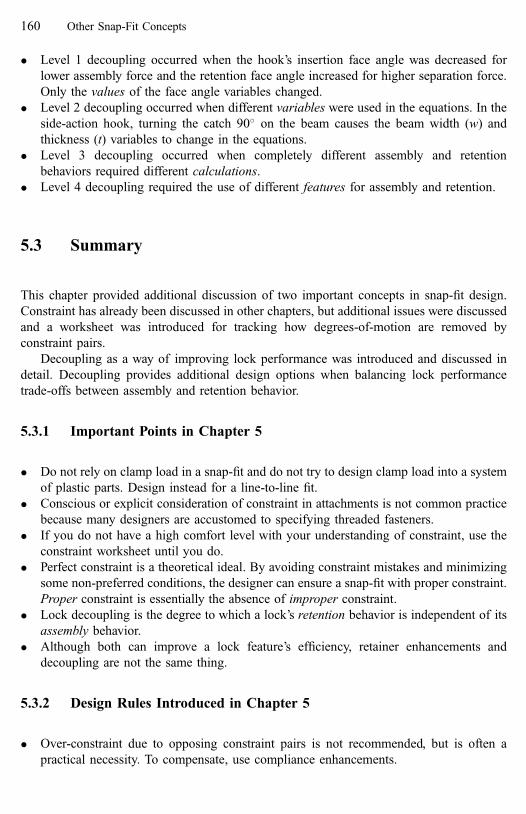
� Level 1 decoupling occurred when the hook’s insertion face angle was decreased for
lower assembly force and the retention face angle increased for higher separation force.
Only the values of the face angle variables changed.
� Level 2 decoupling occurred when different variables were used in the equations. In the
side-action hook, turning the catch 90� on the beam causes the beam width (w) and
thickness (t) variables to change in the equations.
� Level 3 decoupling occurred when completely different assembly and retention
behaviors required different calculations.
� Level 4 decoupling required the use of different features for assembly and retention.
5.3 Summary
This chapter provided additional discussion of two important concepts in snap-fit design.
Constraint has already been discussed in other chapters, but additional issues were discussed
and a worksheet was introduced for tracking how degrees-of-motion are removed by
constraint pairs.
Decoupling as a way of improving lock performance was introduced and discussed in
detail. Decoupling provides additional design options when balancing lock performance
trade-offs between assembly and retention behavior.
5.3.1 Important Points in Chapter 5
� Do not rely on clamp load in a snap-fit and do not try to design clamp load into a system
of plastic parts. Design instead for a line-to-line fit.
� Conscious or explicit consideration of constraint in attachments is not common practice
because many designers are accustomed to specifying threaded fasteners.
� If you do not have a high comfort level with your understanding of constraint, use the
constraint worksheet until you do.
� Perfect constraint is a theoretical ideal. By avoiding constraint mistakes and minimizing
some non-preferred conditions, the designer can ensure a snap-fit with proper constraint.
Proper constraint is essentially the absence of improper constraint.
� Lock decoupling is the degree to which a lock’s retention behavior is independent of its
assembly behavior.
� Although both can improve a lock feature’s efficiency, retainer enhancements and
decoupling are not the same thing.
5.3.2 Design Rules Introduced in Chapter 5
� Over-constraint due to opposing constraint pairs is not recommended, but is often a
practical necessity. To compensate, use compliance enhancements.
160 Other Snap-Fit Concepts
� Over-constraint due to redundant constraint pairs is inefficient.
� An under-constraint condition is unacceptable and must be fixed.
� The common cantilever hook lock is limited in its decoupling ability and caution in its
use is recommended.
� The loop style cantilever lock, the side-action hook and the trap are all higher level
locking devices than the hook and are preferred.
� Applications involving bezels lend themselves to Level 4 decoupling.
References
1. Luscher, A.F., Bonenberger, P.R., 1997, ‘‘Part Nesting as a Plastic Snap-fit Attachment Strategy’’,
DETC97=DTM-3893, Proceedings of DETC ’97, ASME Design Engineering Technical Conference,
September 1997.
2. Bonenberger, P.R., 1995a, ‘‘A New Design Methodology for Integral Attachments’’, ANTEC ’95
Conference of the Society of Plastics Engineers, May 1995, Boston, MA.
5.3 Summary 161

6 Feature Design and Analysis
Analysis and final design of the constraint features is appropriate only after a fundamentally
sound attachment concept has been created. Locator features, in most cases, require little
analytical attention because they are strong and inflexible. Unlike locks, locators are not
required to balance the competing goals of low assembly force and strain with retention
strength. If evaluation of locator strength is required, it normally involves straightforward
and simple shear or compression strength calculations. For that reason, locator feature
calculations are not discussed in this chapter.
Generally, feature design and analysis focuses on locking features because, by their
nature, locks are more complex and have more performance requirements. Lock feature
calculations also represent the traditional ‘‘feature level’’ of snap-fit technical understanding
and are readily available. Therefore, this chapter does not present all available calculations.
Many sources of feature performance calculations exist; some of them are listed at the end of
this chapter and others in Appendix A.
This chapter introduces the material properties needed for feature analysis and then
discusses the common calculations for cantilever hook behavior. By studying these
calculations, the reader will gain an understanding of the (similar) calculations for all of the
beam-based lock styles. Adjustments to the basic cantilever beam calculations are also
explained. The adjustments are important because they can have a significant effect on the
analysis results.
In some instances, in-depth feature calculations are not necessary for initial part
development. The designer simply wishes to create a well-proportioned lock feature that is
manufacturable (process-friendly) and close to the final design intent. To support this
approach, some rules of thumb for initial cantilever lock design are provided. Again, many
of these rules are applicable to other beam-based locks.
In preparation for feature analysis, designers must identify the specific purpose of the
analysis. They must also have access to the data necessary to characterize the material
properties of the part in question. Analysis may involve evaluating features for any or all of
the following, sometimes under multiple environmental conditions:
� Assembly force
� Assembly strain
� Retention strength
� Separation force
� Release strain
For some of the above, analysis requires property data for fresh materials. For others,
data for aged materials may also be needed.

6.1 Pre-Conditions for Feature Analysis
For a credible feature analysis, certain pre-conditions must be met. Feature analysis should
occur only after proper interface constraint is verified. Proper constraint ensures that forces
in the attachment are statically determinate and that only the expected forces (forces to be
considered during analysis) act on the snap-fit features. Constraint was introduced in
Chapter 2 and discussed in more detail in Chapters 3 and 5.
The interface design should be as dimensionally robust as possible. Primary and secondary
datum sites on both parts should be selected with the constraint features in mind. Ideally, the
most dimensionally critical locator pair will be the datum for all other constraint featues. This
reduces the need for close tolerances and means that forces on the features are more predictable.
Always keep in mind the three requirements that apply to analysis: strength, constraint, and
robustness. Of course, the ultimate goal of analysis is ensuring feature strength.
6.2 Material Property Data Needed for Analysis
The intention here is not to make the reader an expert in polymers. The purpose is to
introduce some concepts for basic understanding and encourage the reader to ask intelligent
questions of the resin supplier and=or their own polymers experts. Many times, a material is
selected for a particular application based on appearance and functional requirements. Snap-
fit feature performance is not a prime consideration. The snap-fit must be made to work with
the given material. An appreciation of some materials issues will help the designer recognize
potentially difficult situations early in the development process and know some of the
questions to ask of a polymer expert.
Four material properties normally appear in feature analysis calculations. They are: stress
(s), strain (e), modulus of elasticity (E), and coefficient of friction (m). The earlier in the
development process that the designer has information about these properties, the better.
6.2.1 Sources of Materials Data
Stress-strain and strength information can be found in several forms; some are more useful
than others. Material information in product brochures is appropriate only for general
product comparison or for initial screening of products for an application. It should not be
used for part design or for snap-fit feature analysis.
Material data sheets represent the supplier’s interpretation of laboratory data. Data
sheets are more detailed and useful than brochure information but are, of necessity, based on
general use assumptions and specific test conditions. They only provide data at specific
points (single point data) and their creation is subject to normal differences of data
interpretation. If used for analysis, ensure the data represents the information needed
6.2 Material Property Data Needed for Analysis 163
(a supplier’s terminology may not be the same as yours) and that you fully understand the
conditions under which the data was generated. Be aware that test and sample preparation
procedures may differ between suppliers.
Materials encyclopedias, supplier databases, and universal databases contain informa-
tion similar to that in the materials data sheets. However, different test and sample
preparation methods may make direct comparisons difficult. An exception is the
CAMPUS1 database [1]. CAMPUS1 stands for Computer Aided Material Preselection
by Uniform Standards. The CAMPUS1 database contains data from many plastics
producers, and includes stress-strain curves and other mechanical, thermal, and electrical
properties. One of its primary attractions is that the data is based on uniform testing to ISO
Standards, making direct comparisons of material properties possible. The database is
available to qualified customers of the member companies.
Stress-strain curves are the preferred form of data for snap-fit feature design and
analysis. The stress-strain curves allow the designer and the materials expert to interpret the
data as they see fit for a particular application. The designer must still verify that the
conditions under which the data was generated represent the application. Sometimes, stress-
strain curves need to be generated for a particular set of conditions.
Much of the published stress-strain information is based on tensile testing. Tensile test
data is desirable for tensile loading conditions and acceptable for other conditions when no
other is available, but data generated in tests that represent actual loading conditions is
preferred. For some snap-fit feature analysis, bending is the primary mode of deflection so
stress-strain curves generated by flexural testing would be preferred. For shear conditions,
data generated by shear testing is desirable.
Although stress-strain curves created to closely match the intended use of the material in
the application are preferred, they should also be used with caution. The following quote is
from one resin supplier’s design guide [2] but it is applicable to data from all suppliers.
‘‘Values shown are based on testing of laboratory test specimens and represent data that fall within
the standard range of properties for natural material . . . . These values are not intended for use in
establishing maximum, minimum or ranges of values for specification purposes. [The user] must
assure themselves that the material as subsequently processed meets the needs of their particular
product or use.’’
This means no matter how good the material property data is, it is the result of laboratory
testing under standard conditions. These conditions cannot represent all the variables and
conditions associated with a particular application. End use testing of production parts is
necessary to verify performance.
6.2.2 Assumptions for Analysis
Analysis calculations for plastic, unless otherwise noted, are based on three assumptions
about the material. These are: elastic linearity, homogeneity, and isotropy. In reality, plastics
do not meet these assumptions, although some plastics come closer than others. These
assumptions are necessary however, if we are to apply relatively simple calculations using
traditional equations of structural analysis and they are reasonable for most snap-fit analysis.
164 Feature Design and Analysis [Refs. on p. 217]

One reason these assumptions are acceptable is that, in most cases, predictive analysis of
snap-fit behavior is not an exact science. The effect of these assumptions on the analysis
accuracy is not as significant as are the effects of many other variables on the calculations.
Some of these other effects are discussed in this chapter.
The plastic is linearly elastic. The stress-strain curve is linear in the area of analysis.
(The opposite of elasticity is plasticity.) In reality, most plastics are not linear over the useful
area of their stress-strain curve. We compensate for this by assuming a linear stress-strain
relationship (the secant modulus) for the range of stress and strain in which we are working.
The plastic is homogeneous. The material’s composition is consistent throughout the part
and a small piece of the part will have the same physical properties as the whole part. (The
opposite of homogeneity is heterogeneity.) In reality, plastic part composition depends on many
factors, including raw material mixing, mold flow, and cooling. Proper mold and part feature
design can help ensure that material properties in the areas of analysis are reasonably close to
the predicted properties. Safety factors and conservative calculations can also compensate.
The plastic is isotropic. The physical properties at any point in the material are the same
regardless of the direction in which the sample is tested. (The opposite of isotropy is
anisotropy.) In reality, filled and glass reinforced materials in particular do not exhibit iso-
tropic behavior. Sometimes data for these materials will indicate the direction of testing.
Sometimes the data will only reflect the maximum performance direction. Proper part and mold
design helps ensure that the high performance properties are oriented in the correct directions
in the final part. Values used in analysis should reflect anisotropic behavior if it exists.
6.2.3 The Stress-Strain Curve
The most important information needed for analysis is a material’s stress-strain relationship.
The best way to show this relationship is in a stress-strain curve, a graph of stress vs. strain
for a material under a given set of laboratory test conditions, Fig. 6.1. The initial modulus is
the slope of the stress-strain curve at relatively low stresses and strains. It is a tangent to the
Strain (ε)
Stress
(σ)
E0
Modulus (E) is theslope of a selectedportion of the curve
E = stress/strain
E0 is the initialmodulus
ε
σ
Figure 6.1 The basic stress-strain curve
6.2 Material Property Data Needed for Analysis 165

initial portion of the curve. If the plastic exhibits some linear behavior, the initial modulus
will be the slope up to the proportional limit. Or, if the initial portion is non-linear, the initial
modulus may be reported as a secant modulus, usually at 1% strain.
Unlike the stress-strain curve for steel, where the shape is characteristic of all steels,
stress-strain curves for plastics may be quite different from material to material. This is
another reason why it is good to get the material’s actual stress-strain curves when doing an
analysis. Some typical stress-strain curves for plastics are shown in Fig. 6.2 and the
important points on each curve are defined below. Note that some points do not appear on
every curve. Figure 6.2 and the definitions of terms that follow are from Designing with
Plastic—The Fundamentals, Design Manual TDM-1, courtesy of Ticona LLC, [2]. In the
author’s opinion, this document is an excellent blend of material and design information for
the snap-fit designer who is not a polymer expert. It is highly recommended.
Proportional limit (A). With most materials, some point exists on the stress-strain curve
where the slope begins to change and the linearity ends. The proportional limit is the greatest
stress at which a material is capable of sustaining the applied load without deviating from the
proportionality of stress to strain. This limit is expressed as a pressure in MPa (or in psi) and
is shown as Point A in Fig. 6.2. Note that some materials maintain this proportionality for
large measures of stress and strain, while others show little or no proportionality, as
previously discussed.
Yield point (B). Yield point is the first point on the stress-strain curve where an increase
in strain occurs without an increase in stress. The slope of the curve is zero at this point.
Note that some materials may not have a yield point.
Ultimate strength (C). The ultimate strength is the maximum stress a material withstands
when subjected to an applied load. This is also a pressure expressed in MPa (or psi) and is
denoted by Point C.
Elastic limit (D). Many materials may be loaded beyond their proportional limit and still
return to zero strain when the load is removed. Other materials, particularly some plastics,
have no proportional limit in that no region exists where the stress is proportional to strain
Figure 6.2 Typical stress-strain curve, (Courtesy [2])
166 Feature Design and Analysis [Refs. on p. 217]

(the material obeys Hooke’s law). However, these materials may also sustain significant
loads and still return to zero strain when the load is removed. In either case, point D on the
stress-strain curve represents the point beyond which the material is permanently deformed
if the load is removed. This point is called the elastic limit.
Secant modulus (E). The secant modulus is the ratio of stress to corresponding strain at
any point on the stress-strain curve. For instance, in Fig. 6.2 the secant modulus at Point E is
the slope of the line OE.
Yield strength (F). Some materials do not exhibit a yield point. For such materials, it is
desirable to establish a yield strength by picking a stress level beyond the elastic limit. Although
developed for materials that do not exhibit a yield point, this value is often used for plastics that
have a very high strain at the yield point to provide a more realistic yield strength. This is shown
as Point F on the curves. The yield strength is generally established by constructing a line
parallel to OA at a specified offset strain, Point H. The stress where the line intersects the
stress-strain curve at point F is the yield strength at H offset. For instance, if Point H were at
2% strain, then Point F would be termed the ‘‘yield strength at a 2% strain offset.’’
The three basic types of plastic stress-strain behavior are shown in Fig. 6.3. Toughness is
a measure of a material’s resistance to impact loads and is represented by the area under the
stress-strain curve. Thus, the rigid (brittle) and flexible materials represented here will have
lower toughness than the ductile material. Tough plastics are the preferred materials for
snap-fits. Snap-fits in brittle plastics require very careful design and analysis with particular
caution if impact loads are present in the application. Flexible materials normally do not
lend themselves to snap-fits.
The stress-strain curve is an important source of information for feature analysis. If one
is not available, a reasonable representation can sometimes be constructed [3] from the
information provided on the material data sheet, Fig. 6.4. From this constructed curve, other
values needed for analysis can be estimated. Of course, the accuracy of this curve (or any
stress-strain curve) must be taken into account when interpreting analysis results. If a stress-
strain curve must be constructed, it is useful to find typical curves for similar materials from
Figure 6.3 Plastic toughness vs. brittleness vs. flexibility
6.2 Material Property Data Needed for Analysis 167
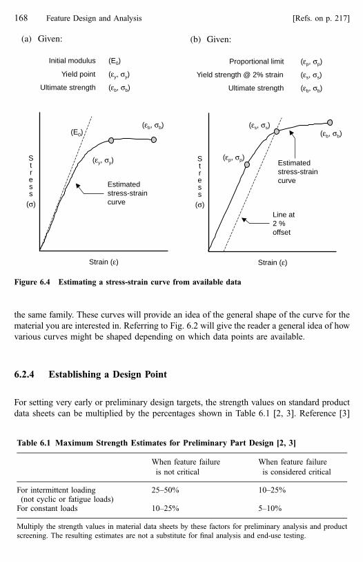
the same family. These curves will provide an idea of the general shape of the curve for the
material you are interested in. Referring to Fig. 6.2 will give the reader a general idea of how
various curves might be shaped depending on which data points are available.
6.2.4 Establishing a Design Point
For setting very early or preliminary design targets, the strength values on standard product
data sheets can be multiplied by the percentages shown in Table 6.1 [2, 3]. Reference [3]
(a) Given:
Initial modulus (E0)
Yield point (εy, σy)
Ultimate strength (εb, σb)
Estimatedstress-straincurve
Strain (ε)
Stress
(σ)
(E0)
(εy, σy)
(εb, σb)
(b) Given:
Proportional limit (εp, σp)
Yield strength @ 2% strain (εs, σs)
Ultimate strength (εb, σb)
Estimatedstress-straincurve
Strain (ε)
Stress
(σ)
(εs, σs)(εb, σb)
(εp, σp)
Line at2 %offset
Figure 6.4 Estimating a stress-strain curve from available data
Table 6.1 Maximum Strength Estimates for Preliminary Part Design [2, 3]
When feature failure
is not critical
When feature failure
is considered critical
For intermittent loading(not cyclic or fatigue loads)
25–50% 10–25%
For constant loads 10–25% 5–10%
Multiply the strength values in material data sheets by these factors for preliminary analysis and product
screening. The resulting estimates are not a substitute for final analysis and end-use testing.
168 Feature Design and Analysis [Refs. on p. 217]

also provides a much deeper discussion of safety factors and the introduction of other factors
reflecting materials and processing effects into determining the design point.
For final analysis, establishing the design point from a stress-strain curve is recommended.
The design point represents the maximum stress and strain allowed in the feature being
analyzed. The design point also establishes the secant modulus. It may be necessary to determine
several design points using several stress-strain curves, each one representing a different
condition under which the snap-fit is expected to perform. It may also be necessary to ask the
supplier to generate curves representing specific conditions for the application. Conditions for
which a design point should be established include both short- and long-term considerations.
Typical short-term conditions may be a new=fresh material at room temperature. This
would be generally appropriate for evaluating initial assembly behavior unless initial
assembly involves temperature extremes or aged material. Typical long-term conditions
would comprehend the applied load history, expected number of assembly=disassembly
cycles, thermal, ultra-violet, and chemical aging effects, material creep properties and
ambient temperature effects.
Once stress-strain curves have been obtained, the following guidelines can be used to
establish an initial design point for each curve.
6.2.4.1 For Applications Where Strain is Fixed
These are applications in which a feature is deflected during assembly then remains at some
level of deflection for the life of the product. This is a long-term loading condition,
� For ductile and high-elongation plastics set the maximum permissible strain at 20% of
the yield point or yield strain, whichever is lower, Fig. 6.5a.
� For brittle and low-elongation plastics that don’t exhibit yield set the maximum
permissible strain at 20% of the strain at break, Fig. 6.5b.
(a) For ductile and high-elongation plastics
Strain (ε)
Yieldpoint
Stress
(σ)
εmax = 20% of εyield
εmax εyield
(b) For brittle and low-elongation plastics
Strain (ε)
Breakpoint
Stress
(σ)
εmax = 20% of εbreak
εmax εbreak
Figure 6.5 Design points for fixed strain applications
6.2 Material Property Data Needed for Analysis 169

6.2.4.2 For Applications Where Strain is Variable
The assembly process itself involves a change in strain. When deflections occur very rapidly,
as in assembly or impact loading, feature analysis should be based on dynamic strain, not on
stress or static strain. Because of the time-dependence of plastic behavior, it is very possible
for calculated stress to exceed the stress at yield without causing damage when deflection
occurs rapidly. When loads or deflections occur rapidly, as they do during assembly, use the
dynamic strain limit when determining the design point. When loads or deflections occur
more slowly, as during disassembly or sustained loading, maximum allowable stress or static
strain values can be used in the calculations.
Some suppliers may recommend a maximum working stress level in their material
design information. Use stress for evaluating long-term loading conditions.
Two material situations apply in applications with variable strain:
6.2.4.3 Materials With a Definite Yield Point
For a low number of assembly=disassembly cycles (�1–10 cycles), set the maximum
permissible strain at 70% of the strain at yield, Fig. 6.6a. [3]
For higher assembly=disassembly cycles (>10 cycles), set the maximum permissible
strain at 40% of the strain at yield, Fig. 6.6b.
6.2.4.4 Materials Without a Definite Yield Point
For a low number of assembly=disassembly cycles (�1–10 cycles), set the maximum
permissible strain at 50% of the strain at break, Fig. 6.7a. [3]
For higher assembly=disassembly cycles (>10 cycles), set the maximum permissible
strain at 30% of the strain at break, Fig. 6.7b.
(a) For a low number (~1–10) ofassembly/disassembly cycles
Strain (ε)
εmax εyield
Yieldpoint
Stress
(σ)
εmax = 70% of εyield
(b) For a higher number ofassembly/disassembly cycles
Strain (ε)
Yieldpoint
Stress
(σ)
εmax = 40% of εyield
εmax εyield
Figure 6.6 Design points for variable strain application having a definite yield point
170 Feature Design and Analysis [Refs. on p. 217]

6.2.4.5 The Secant Modulus
Once a design point is established, the secant modulus (Es) is the slope of a line from the
origin through the design point, Fig. 6.8. The secant modulus will be used in the analysis
calculations.
6.2.4.6 Maximum Permissible Strain Data
Values for maximum permissible strain of some groups and families of materials are given in
Table 6.2. These can be useful for estimating initial performance but they should not be used
for final analysis.
(a) For a low numberassembly/disassembly cycles
Strain (ε)
Stress
(σ)
Ultimatestrength
εmax εultimate
εmax = 50% of εultimate
(b) For a higher number ofassembly/disassembly cycles
Strain (ε)
Stress
(σ)
Ultimatestrength
εmax εultimate
εmax = 30% of εultimate
(~1–10) of
Figure 6.7 Design points for variable strain application without a definite yield point
,
Figure 6.8 Calculating the secant modulus from the design point
6.2 Material Property Data Needed for Analysis 171

This concludes the discussion of stress and strain. Important points to remember include:
� Published data in brochures is acceptable for initial screening but material data sheets
and preferably actual stress-strain curves should be used to establish the design points for
final analysis.
Table 6.2 Maximum Permissible Strain
Material Typical emax Source
Most plastics fall within 1–10% X
Glass filled plastics tend to fall within 1–2% X
Polypropylene PP 8–10% X
Polycarbonate 30% glass-fiber reinforced PC 1.8% X
Polyphenylenesulfide (40% glass-fiber reinforced) PPS 1% X
High heat polycarbonate PC 4% B
Polycarbonate=ABS blend 2.5% B
Acrylonitrile-styrene-acrylate ASA 1.9% B
Polycarbonate blends 3.5% B
Polycarbonate PC 4% B
Polyamide (conditioned) PA 6% B
Polyamide (dry) PA 4% B
Polyamide=ABS 3.4% B
Acrylonitrile-butadiene-styrene ABS 1.8% B
Polycarbonate (10% glass reinforced) 2.2% B
Polyamide=ABS (15% glass reinforced) 2.2% B
Polycarbonate (20% glass reinforced) 2% B
Polyamide conditioned (30% glass reinforced) 2% B
Polyamide dry (30% glass reinforced) 1.5% B
Polyetherimide PEI 9.8% A
Polycarbonate PC 4–9.2% A
Acetal 1.5% A
Nylon 6 (dry) 8% A
Nylon 6 (30% glass reinforced) 2.1% A
Polybutylene terephthalate PBT 8.8% A
Polycarbonate=Polyethylene terephthalate PC=PET 5.8% A
Acrylonitrile-butadiene-styrene ABS 6–7% A
Polyethylene terephthalate PET (30% glass reinforced) 1.5% A
B—Snap-fit Joints for Plastics¼ a design guide, Polymers Division, Bayer Corp., 1998.
A—Modulus Snap-Fit Design Manual, Allied Signal Plastics, 1997.
X—Unidentified.
� Materials in the table are unreinforced unless noted otherwise.
� These values are for short-term strain and low cycle or single cycle operation. For multiple cycles, use
60% of the values shown.
� The strain data is at room temperature.
� ‘‘Conditioned’’ refers to standard test conditions of 50% relative humidity and 20 �C, unless other
specific humidity=temperature conditions are noted.
� ‘‘Dry’’ means low or no moisture content. Often it is ‘‘dry as molded’’.
172 Feature Design and Analysis [Refs. on p. 217]

� Use stress-strain data that represents actual application conditions.
� Permissible strain tends to be higher for ductile and lower for brittle polymers.
� Recognize that many conditions may affect the actual maximum permissible strain and
that end-use testing is necessary to verify predicted performance.
6.2.5 Coefficient of Friction (m)
Coefficient of friction relates the normal force acting on an interface to the force required to
slide one of the interface members across the other. It is used when calculating assembly or
separation forces and retention strength, all situations where one snap-fit feature must slide
across another.
Coefficient of friction is related to the lubricity of a material. Lubricity is the load
bearing capability of the material under relative motion. It is a measure of the material’s
ability to slide across another material or itself without galling or other surface damage.
Materials with good lubricity will tend to have lower coefficients of friction. Those with poor
lubricity will tend to have higher coefficients of friction. Information about a material’s
lubricity can sometimes be found in its data sheet.
Some published coefficient of friction values are shown in Table 6.3. However, be aware
that published values are based on specific tests and materials that may have little or no relation
to a specific application or to the common snap-fit condition of an edge sliding over a retention
feature surface. The best source of friction data is testing under actual conditions, but this is
rare. Use the published data along with lubricity information and your own judgment to
determine a coefficient of friction. From the data shown, one can see that values ofm range from
0.2 to 0.7. For initial analysis, unless other information is available, values of 0.2 for low
friction materials and 0.4 for high friction materials are reasonable estimates. Coefficient of
friction variability has a strong effect on the reliability and accuracy of assembly and retention
calculations.
The data in Table 6.3 from source [4] was associated with information on spin-welding
and was most likely developed with that technology in mind. However, it is useful in that it
shows the kind of variation that can occur depending on the test. Note the difference
between steel vs. polypropylene and polypropylene vs. steel, for example. All the published
coefficient of friction data should be considered by the designer as information that will
allow for an educated estimate of the friction value(s) for use in analysis.
We will also see that it is desirable to have estimates of the coefficient of friction under
both static and dynamic conditions. Again, unless application specific tests are run to gene-
rate this data, an educated adjustment to the available published data will be necessary.
6.2.6 Other Effects
Plastic materials have many other properties that, while they do not appear in the calculations,
can influence analysis because of their effect on stress and strain behavior. Some will also
affect the dimensional stability of the parts.
Additives are chemicals added to enhance certain functional or processing capabilities of
a plastic. Because additives may adversely affect mechanical properties, they can affect
6.2 Material Property Data Needed for Analysis 173
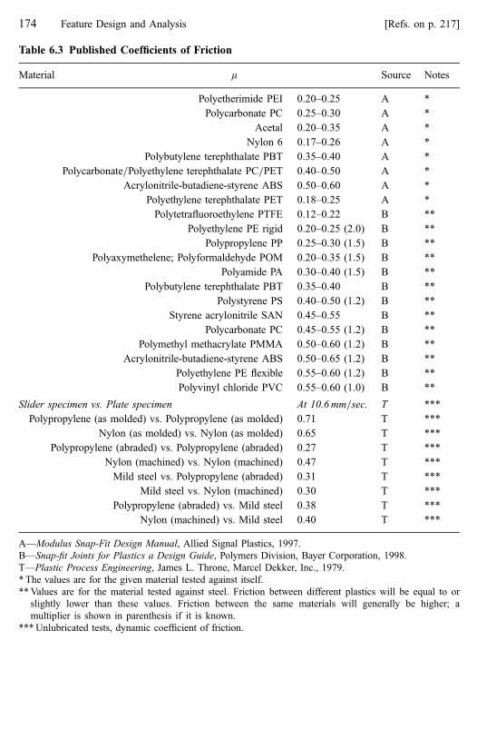
Table 6.3 Published Coefficients of Friction
Material m Source Notes
Polyetherimide PEI 0.20–0.25 A *
Polycarbonate PC 0.25–0.30 A *
Acetal 0.20–0.35 A *
Nylon 6 0.17–0.26 A *
Polybutylene terephthalate PBT 0.35–0.40 A *
Polycarbonate=Polyethylene terephthalate PC=PET 0.40–0.50 A *
Acrylonitrile-butadiene-styrene ABS 0.50–0.60 A *
Polyethylene terephthalate PET 0.18–0.25 A *
Polytetrafluoroethylene PTFE 0.12–0.22 B **
Polyethylene PE rigid 0.20–0.25 (2.0) B **
Polypropylene PP 0.25–0.30 (1.5) B **
Polyaxymethelene; Polyformaldehyde POM 0.20–0.35 (1.5) B **
Polyamide PA 0.30–0.40 (1.5) B **
Polybutylene terephthalate PBT 0.35–0.40 B **
Polystyrene PS 0.40–0.50 (1.2) B **
Styrene acrylonitrile SAN 0.45–0.55 B **
Polycarbonate PC 0.45–0.55 (1.2) B **
Polymethyl methacrylate PMMA 0.50–0.60 (1.2) B **
Acrylonitrile-butadiene-styrene ABS 0.50–0.65 (1.2) B **
Polyethylene PE flexible 0.55–0.60 (1.2) B **
Polyvinyl chloride PVC 0.55–0.60 (1.0) B **
Slider specimen vs. Plate specimen At 10.6 mm=sec. T ***
Polypropylene (as molded) vs. Polypropylene (as molded) 0.71 T ***
Nylon (as molded) vs. Nylon (as molded) 0.65 T ***
Polypropylene (abraded) vs. Polypropylene (abraded) 0.27 T ***
Nylon (machined) vs. Nylon (machined) 0.47 T ***
Mild steel vs. Polypropylene (abraded) 0.31 T ***
Mild steel vs. Nylon (machined) 0.30 T ***
Polypropylene (abraded) vs. Mild steel 0.38 T ***
Nylon (machined) vs. Mild steel 0.40 T ***
A—Modulus Snap-Fit Design Manual, Allied Signal Plastics, 1997.
B—Snap-fit Joints for Plastics a Design Guide, Polymers Division, Bayer Corporation, 1998.
T—Plastic Process Engineering, James L. Throne, Marcel Dekker, Inc., 1979.
* The values are for the given material tested against itself.
** Values are for the material tested against steel. Friction between different plastics will be equal to or
slightly lower than these values. Friction between the same materials will generally be higher; a
multiplier is shown in parenthesis if it is known.
*** Unlubricated tests, dynamic coefficient of friction.
174 Feature Design and Analysis [Refs. on p. 217]

snap-fit feature performance. Examples of additives include impact modifiers, UV
stabilizers, coloring agents, and flame-retardants.
Plastics will exhibit accelerated aging at elevated temperatures. All plastics will
experience degradation of mechanical properties at elevated temperatures over the long term.
A comparison of thermal stability values will indicate the severity of the degradation.
Sometimes stress-strain curves are generated to show performance at elevated temperatures.
Creep is a relatively long-term increase in strain (i.e., deflection) under a sustained load.
The rate of creep for a material depends on the applied stress, temperature, and time. Stress-
strain curves showing the effects of long-term creep are required for long-term performance
analysis. From these curves, a creep modulus can be determined and used in the calculations.
Plastic properties are sensitive to temperature effects. In general, materials become softer
and more ductile and the modulus decreases with increasing temperature. The deflection
temperature under load (DTUL), also called the heat deflection temperature or HDT, is a single
point measurement that may be useful for quality control or for initial screening of materials
for short-term heat resistance. However, the DTUL value should not be used as design data.
Fatigue endurance. For applications subjected to cyclic loads, SN curves can be generated.
Cyclic loading, particularly reversing loads, can significantly reduce the life of a plastic part.
Notch sensitivity is the ease with which a crack propagates through a material from a
notch, initial crack, or a corner. A stress concentration factor related to the effect of sharp
corners on local stress should be included in all calculations.
Chemical and ultra-violet effects may degrade mechanical properties. In general, as tem-
perature and=or stress level increases, the plastic’s resistance to these other effects will decrease.
Mold design and part processing can affect feature performance. Thick sections and
improper cooling can cause voids or internal stresses. Mold flow patterns, knit lines, and
placement of gates can adversely affect feature strength. Identical features in different areas
of a part may have different strength and strain capabilities.
Plastic behavior is rate dependent. This means it is affected by the speed of the applied
load. Stress-strain tests are conducted at a standard speed and may not represent actual load
rate in an application. For a given plastic, a high load rate will typically result in behavior
similar to that at a low temperature: more rigid and brittle. A slow load rate results in
behaviors similar to high temperature behavior (more ductile and flexible), Fig. 6.9.
Figure 6.9 Effects of temperature and strain rate on stress-strain behavior (courtesy of TiconaLLC, Designing With Plastic—the Fundamentals)
6.2 Material Property Data Needed for Analysis 175

The amount of recycled content or regrind as well as the effectiveness of the material
mixing process (for uniformity) prior to molding can affect mechanical properties and
part-to-part consistency.
Stress relaxation is a relatively long-term decrease in stress under a constant strain. (Creep
involves constant stress; stress relaxation involves constant strain.) Data similar to creep data
can be generated and a relaxation modulus determined, but relaxation data are not as available
as creep data. The creep modulus can be used as an approximation of the relaxation modulus.
Toughness is the ability to absorb mechanical energy (impact) through elastic or plastic
deformation without fracturing. Material toughness is measured by the area under the stress-
strain curve. Tests for impact resistance under specific conditions include the Izod and
Charpy tests of notched specimens, the tensile impact test, and the falling dart impact test.
Water absorption. Some plastics, nylons for example, are very susceptible to moisture
and humidity levels. Moisture content can affect mechanical properties as well as
dimensional stability. Materials with low water absorption have better dimensional stability.
Mechanical properties are often given at two humidity conditions: Dry as molded (DAM)
and 50% relative humidity. Moisture content can affect mechanical properties (especially
stiffness), electrical conductivity, and dimensional stability. Nylon is particularly susceptible,
use impact modified nylon to minimize moisture sensitivity.
Coefficient of Linear Thermal Expansion (CLTE) is a measure of the material’s linear
dimensional change under temperature changes. The lower the CLTE, the greater the
dimensional stability. The mating and base parts should have similar values of CLTE if
possible. Careful consideration of constraint and compliance during feature selection will
minimize the effects of CLTE differentials. Table 6.4 shows CLTE values for some plastics
and, for comparison, some common metals.
Use CLTE to estimate compliance requirements in the interface, particularly when parts
are large or differences between the expansion rates of the joined materials are significant.
When these conditions exist, it is also more important to avoid over-constraint due to
opposing features in the interface.
Mold shrinkage. Percentage of part shrinkage as it cools from the actual mold shape will
affect final dimensions. In general, amorphous plastics have lower shrinkage than crystalline
and glass-filled are lower than unfilled (neat) plastics. An excellent source of tolerance data
for a wide variety of polymers is reference [5].
6.3 Cantilever Hook Design Rules of Thumb
The rules that follow are generally true, but material, part, and processing variation will affect
their suitability for any given application. They can be useful for setting some nominal feature
dimensions and providing a starting point for analysis. By taking the materials properties and
variables discussed in the preceding section into account, the designer will be able to bias
these rules of thumb in the right direction for more accurate estimates of dimensions.
Some of these guidelines are related to processing capabilities and following them can help
avoid marginal processing situations that may cause inconsistent feature performance. As
always, feature performance, especially on critical applications, must be verified by analysis
and end-use testing.
176 Feature Design and Analysis [Refs. on p. 217]

Reflecting its popularity, there are many rules of thumb for the cantilever hook lock but
few for other lock types. The rules are presented here in a logical order for most hook
development situations. However, the designer should always keep in mind that hook design
is frequently an iterative process. Initial dimensions are likely to require adjustment to
account for design decisions made later in the process. Refer to Fig. 6.10 for the terminology
used in the rules that follow. Many of these rules are also applicable to the other beam style
locks and a few apply to all features that protrude from a wall or surface.
These rules of thumb are also very useful when doing quick screening of a proposed
design or diagnosis of a problem application where beam-style locks are used. Look
especially for gross rule violations. For example, when a cantilever hook feature with a 2 : 1
length to thickness ratio appears in an application, calculations are not needed to know that
there will be problems with it.
Table 6.4 Published Coefficients of Linear Thermal Expansion (CLTE)
Material in.=in.=�F 10�5 cm=cm=�C 10�5
Liquid crystal (GR*) 0.3 0.6
Glass 0.4 0.7
Steel 0.6 1.1
Concrete 0.8 1.4
Copper 0.9 1.6
Bronze 1.0 1.8
Brass 1.0 1.8
Aluminum 1.2 2.2
Polycarbonate (GR) 1.2 2.2
Nylon (GR) 1.3 2.3
TP polyester (GR) 1.4 2.5
Magnesium 1.4 2.5
Zinc 1.7 3.1
ABS (GR) 1.7 3.1
Polypropylene (GR) 1.8 3.2
Epoxy (GR) 2.0 3.6
Polyphenylene sulfide 2.0 3.6
Acetal (GR) 2.2 4.0
Epoxy 3.0 5.4
Polycarbonate 3.6 6.5
Acrylic 3.8 6.8
ABS 4.0 7.2
Nylon 4.5 8.1
Acetal 4.8 8.5
Polypropylene 4.8 8.6
TP polyester 6.9 12.4
Polyethylene 7.2 13.0
Courtesy of Ticona LLC, Designing With Plastic—the Fundamentals.
Also see [11] for additional CLTE data.
* GR indicates a glass-reinforced material.
6.3 Cantilever Hook Design Rules of Thumb 177

6.3.1 Beam Thickness at the Base
Because the parent component dimensions and characteristics are usually fixed, they are the
first constraints on feature design. Thus, we will start where the hook meets the parent
Dimensions shown in the hook drawings:Lr Retention feature lengthLb Beam lengthLt Total lock feature lengthTw Wall thickness at the beamTb Beam thickness at the wall Tr Beam thickness at the retention featureRw Radius at the beam to wall intersectionWb Beam width at the wallWr Beam width at the retention featureY Undercut depth
α Insertion face angle
β Retention face angle
Other dimensions:
δ Assembly deflection (may be equal to Y)
Le Effective beam length (The distance from the base of the beam to the mating feature’s point of contact on the insertion or retention face.)
Tw
LrLb
Tb
Lt
Tr
YRw α
β
WrWb
Le
Figure 6.10 Cantilever hook variables and terminology
178 Feature Design and Analysis [Refs. on p. 217]

component. A beam may extend from a wall or surface in many ways, the most common are
a 90� protrusion and in-plane.
If the beam protrudes from a wall, Fig. 6.11a, then the beam thickness at its base (Tb)
should be about 50 to 60% of wall thickness. Beams thinner than 50% may have filling and
flow problems. Beams thicker than 60% may have cooling problems at the base because of
the thick section. This may, in turn, lead to high residual stresses and voids which will
weaken the feature (at its point of highest stress) and sink marks on the opposite side of the
wall which are unacceptable on an appearance surface.
If the beam is an extension of a wall, Fig. 6.11b, then (Tb) should be equal to the wall
thickness. If the beam thickness must be less than the wall thickness, then a gradual change
in thickness over a length of the beam (at a 1 : 3 rate) from the wall to the desired beam
thickness should be used to avoid stress concentrations and mold filling problems.
6.3.2 Beam Length
The total cantilever hook length (Lt) is made up of beam length (Lb) and retention feature length
(Lr), Fig. 6.12. These two are considered separately because when bending is calculated, only
the flexible beam portion of the hook is included. Retention feature length is not known, but we
can establish the beam length now. Later, we can add retention feature length to beam length for
total hook length. Ideally, we want to be free to select a beam length without any restrictions,
but often total beam length is limited by available space or mating part dimensions.
Beam length (Lb) should be at least 5� beam thickness (5� Tb) but closer to 10�thickness (10� Tb) is preferred. Beams can be longer than 10� thickness, but warpage and
filling may become problems. Check the design against the material’s spiral flow curves to
ensure adequate feature filling.
(a) Perpendicular to a wall (out of plane) (b) In-plane from an edge
Tb should be 50% to 60% of the wall thickness
Tb
Tw
Tb
Tb should be equal to the edge thickness
Figure 6.11 Initial beam thickness
6.3 Cantilever Hook Design Rules of Thumb 179

Beams shorter than (5� Tb) will experience significant shear effects as well as bending
at the base. Not only does this increase likelihood of damage during assembly, it renders the
analytical calculations (based on beam theory) much less accurate. Shorter beams are much
less flexible and create higher strains at the base. Longer beams are more flexible for
assembly but also become weaker for retention.
Higher length to thickness ratios are recommended for plastics that are harder and more
brittle.
6.3.3 Insertion Face Angle
Insertion face angle will affect the assembly force. The steeper the angle, the higher the force
required to deflect and engage the hook.
Ideally, the insertion face angle should be as low as possible for low assembly force,
Fig. 6.13. An angle of 25�–35� is reasonable. Angles of 45� or greater are difficult to
assemble and should be avoided. For the common cantilever hook, the initial insertion face
angle will also increase during insertion; another good reason to start out with that angle as
low as possible. This change in insertion face angle is discussed in a later section.
6.3.4 Retention Face Depth
The retention face depth (Y), sometimes called ‘‘undercut,’’ determines how much the beam
will deflect during engagement and separation, Fig. 6.14a. (‘‘Separation’’ means both
unintended release due to an external force or intentional release for disassembly.) For a
Beam length (Lb) should be at least 5 x Tb
A length of 10 x Tb is preferred
Beam
Retention mechanism
LrLb
Lt
Tb
Figure 6.12 Initial beam length
180 Feature Design and Analysis [Refs. on p. 217]

beam length (Lb) to thickness (Tb) ratio in the range of 5 : 1, the initial retention face depth
(Y) should be less than Tb. For a Lb=Tb ratio close to 10 : 1, the initial retention face depth
can be equal to Tb. Harder and more rigid plastics (higher modulus) can tolerate less
deflection for a given length than can softer plastics.
Generally, for the beam=catch hook, the full retention face depth should be used for hook
deflection and return. Thus retention face depth will equal deflection (Y¼ d). This helps
ensure that separation forces on the catch occur as close as possible to the neutral axis of the
beam and minimizes rotational forces at the end of the beam that would contribute to
unintended release.
When analysis calculations are based on a known strain limit for the material, a
maximum allowable deflection can be determined. The maximum retention face depth is
then set equal to the maximum allowable deflection.
6.3.5 Retention Face Angle
Retention face angle will affect retention and separation behavior. The steeper the angle, the
higher the retention strength and the disassembly force, Fig. 6.14b.
–
Figure 6.13 Initial insertion face angle
(b) Retention face angle
β ~ 45o for a releasing lock with no external separation loads
β > 55o for a releasing lock with low external separation loads
β ~ 80o– 90o for a non-releasing lock with higher separation loads
β
(a) Retention face depth
For Lb/Tb ~ 5, set Y < Tb
For Lb/Tb ~ 10, set Y = Tb
Y
Tb
Figure 6.14 Initial retention face depth and angle
6.3 Cantilever Hook Design Rules of Thumb 181

For a releasing lock where no external separation forces are acting on the mating part
(aside from an intentional manually applied separation force), a retention face angle of about
35� is generally acceptable, Fig. 6.14b. The exact angle will depend on the coefficient of
friction between the materials and the actual stiffness of the lock material. If the application
is one with an expected high number of usage cycles (as with a moveable snap-fit), then a
lower angle is preferred to reduce cyclic loading on both the lock and the mating feature. If
the lock will be released only a limited number of times, then a higher angle may be possible.
If some relatively low external separation forces are expected, then a retention face angle
of about 45� is a reasonable starting point. Again, consider friction and hook stiffness. These
locks may still be a releasing style, but manual separation forces will be high and a high
number of removal cycles is not recommended.
If the lock must resist high external separation forces, then a releasing lock is not
recommended and a permanent or non-releasing (manual deflection needed for disassembly)
lock should be designed. The retention face angle should be close to 90�. A retention face
angle of exactly 90� usually is not necessary. Because of frictional effects, any angle above a
limiting value called the threshold angle will behave like a 90� angle.
6.3.6 The Threshold Angle
Because of friction between the feature contact surfaces, an angle less than 90� can still
behave like a 90� angle. At a coefficient of friction of 0.3, this threshold angle is
approximately 80�. This means that any angle above 80� will behave like an angle of 90�.The threshold angle is a function of coefficient of friction and can be calculated if the
coefficient is known by solving the basic retention force formula for b:
bthreshold ¼ tan�1 1
m
� �ð6:1Þ
Using an angle between the threshold angle and 90� on the retention face may sometimes
be desirable because it will have slightly more dimensional compliance and robustness than
a 90� angle can provide, Fig. 6.15.
6.3.7 Beam Thickness at the Retention Feature
Often the beam thickness at the retention face (Tr) is equal to the thickness at the feature
base (Tb), Fig. 6.16a. However, when strains at the base are high, tapering the beam over its
length will more evenly distribute strain through the beam and reduce the chances of over-
strain at the base, Fig. 6.16b. Common taper ratios (Tb : Tr) range from 1.25 : 1 up to 2 : 1. In
shorter beams, tapering can reduce strains at the base by as much as 60%. However, tapering
will also reduce the retention strength. Tapering is one possible solution to high strains when
design constraints force a beam to violate the 5 : 1 minimum length to thickness rule.
Do not taper a cantilever beam from the retention face to the base. This moves virtually
all the strain to the base of the hook and damage is very likely, Fig. 6.16c.
182 Feature Design and Analysis [Refs. on p. 217]

Figure 6.15 Retention face threshold angle
(b) A 2:1 taper (Tb = 2 × Tr) is common
Improved strain distribution along thebeam means lower strain at the wall,particularly in shorter beams
Tb
Tr
(a) No taper, Tb = Tr
Tb Tr
(c) Improper taper, Tb < Tr
Figure 6.16 Beam thickness at end, constant section beam and tapered beam
6.3 Cantilever Hook Design Rules of Thumb 183

6.3.8 Beam Width
Most beams have a constant width from the base to the retention face. When this is the case,
beam width does not affect the maximum assembly strain but it does affect assembly and
disassembly forces and retention strength. The fact that strain is not a function of beam
width when the width is constant means that beam strength can be increased by increasing
width without increasing the strain, Fig. 6.17a. This can be an alternative to increasing the
beam thickness when more retention strength is needed.
For beam theory to apply, the width should be less than or equal to the length, Fig. 6.17b.
As the width becomes greater than 1=2 the length, the feature begins to behave more like a
(c) Width-tapered hooks
Beam with 4:1 widthtaper
Beam extending froman edge
Beam tapered on bothwidth and thickness
Wb
Lb
Wr
(a) No taper on width, Wb = Wr.
Lower assembly force andretention strength
Higher assembly forceand retention strengthFor otherwise equivalent
hooks, the maximum strainwill not change with beamwidth
(b) Effect of high beam width
This hook isapproachingplate-likebehavior
Wb
Lb
Wb
Lb
As beam width to length ratio increases, behavior becomes less like a beam and more like aplate, the threshold is roughly Wb > Lb
Figure 6.17 Beam width
184 Feature Design and Analysis [Refs. on p. 217]

plate than a beam. However, given the other variables involved in the calculations, relatively
minor inaccuracies at higher beam widths can generally be ignored.
Beams can be tapered on width, just as they can be tapered on thickness, Fig. 6.17c.
Tapering the beam in the width dimension can reduce strain at the base, but not as effectively
as tapering the thickness. Where a beam extends in-plane from an already thin wall, tapering
the width may be the only option.
A beam must have a 4 : 1 taper in width for the level of same strain reduction as a beam
with a 2 : 1 taper in thickness.
6.3.9 Other Features
The rules given here for the cantilever hook can often be used to establish initial dimensions
for other lock feature styles. For example, rules for insertion and retention face angles are
generally applicable to catch-like retention features used in torsional lock configurations and
on walls. Rules for beam bending can be applied to both the loop and trap lock styles.
6.4 Initial Strain Evaluation
With these intial values for the hook dimensions, we know beam deflection, thickness and
length. If the beam width is constant, a quick preliminary calculation of the maximum
assembly strain at the base can be made:
einitial ¼ 1:5TbdL2
ð6:2Þ
The result can be compared to the maximum allowable strain. (Remember, for evaluating
assembly behavior use the dynamic strain limit if it is available.) This early calculation will
indicate if the proposed hook design is reasonably close to the maximum allowable strain.
Do not worry if the calculated strain is over the allowable strain by as much as 50%. Other
conditions not yet considered will tend to reduce the actual strain in the final analysis. As
you become familiar with how these conditions affect strain, you will develop a feeling for
just how these effects will influence the final strain numbers. The conditions include:
� Possible parent material deflection at the feature’s base during assembly.
� Possible mating feature deflection during assembly.
On the other hand, if the calculation indicates the maximum strain far exceeds the per-
missible strain (e.g., by 100% or more), then changes to the initial beam dimensions (thickness,
length, or retention face depth) can be made. A glance at the deflection magnification effects for
the hook=wall configuration being designed will also give an indication of how much the
calculated strain will be reduced and whether an adjustment is necessary at this time.
Again, keep in mind that the rules presented in this section are useful for establishing
initial dimensions for a cantilever hook or other snap-fit feature. Analysis and end use
6.4 Initial Strain Evaluation 185

testing are still required to ensure feature performance meets all application requirements. To
summarize some earlier remarks:
� These are general rules of thumb and, in some cases, reflect preferred design practices
for ease of molding.
� They can be useful for setting some nominal feature dimensions that provide a starting
point for analysis.
� They are useful for initial feature screening and identifying gross violations.
� They can help avoid marginal processing situations that may cause inconsistent feature
performance.
� Analyzing plastic features involves many variables and some assumptions. It is not an
exact science.
� Feature design is often an iterative process, but good initial design will minimize the
number of iterations. Designing for feature robustness and following metal-safe
principles to enable fine-tuning is highly recommended.
� Feature performance, especially on critical applications, should be estimated by analysis
and verified by end-use testing.
6.5 Adjustments to Calculations
Cantilever hook analysis is based on classic structural beam theory. Adjustments to the
results are necessary to more closely reflect real part behavior. Before feature calculations
are discussed in detail, we will introduce several important adjustments to the basic beam
calculations. They are:
� Stress concentrations (k), where abrupt changes in section can cause an increase in local
strain. Stress concentrations tend to increase the actual strain at the base of the beam so
they reduce the maximum allowable calculated strain. Although called ‘‘stress
concentrations’’, it is appropriate to apply the adjustment to strain in the calculations
when we are not working with stress.
� Wall deflection, expressed as a deflection magnification factor (Q), where wall deformation
tends to reduce the actual strain and increase the actual deflection of a hook under a given
load. Deflection magnification will also tend to reduce retention strength.
� Mating feature deflection (dm), where some assembly deflection occurs in the other
member of the lock pair. Mating feature deflection will tend to reduce assembly
deflection and strain as well as separation strength.
� Effective angle (ae and be), where assembly and separation deflections change the insertion
and retention face angles and affect the predicted performance of the lock. Effective angle
does not affect strain, but can have significant effects on assembly force and retention strength.
6.5.1 Adjustment for Stress Concentration
Stress concentrations occur where the feature undergoes a sudden change in section. The
effect of stress concentrations is to increase the actual strain in the part above the strain
186 Feature Design and Analysis [Refs. on p. 217]

calculated from beam theory. For hooks and beams in general, we are most concerned with
the area stressed in tension where the feature meets a wall. A radius at that location will
reduce stress concentration effects, but they cannot be totally eliminated.
Figure 6.18 shows a curve for the stress concentration factor (k) vs. the ratio of beam
thickness to the radius at the beam to wall juncture. Other sources show curves similar to this
one. As shown in the graph, a value of k¼ 1.5 is reasonable. A stress concentration factor of
1.0 is impractical because the very large radius required would result in voids, residual
stresses and sink marks. Rules for process-friendly design also limit this radius to about 50%
of beam thickness.
The stress concentration factor (k) can be applied in one of two ways. It can be used to
increase the calculated strain for comparison to the design strain or it can reduce the design
strain for comparison to the calculated strain.
As shown in Equation 6.3, we will use the stress concentration factor to reduce the
design strain to a maximum allowable strain. This will leave the calculated strain unaffected
so it can be adjusted by other factors and used in other calculations.
The stress concentration factor is used to reduce the design strain:
emax ¼ edesign
kð6:3Þ
Our maximum allowable strain target is now:
ecalc < emax ð6:4ÞThere also seems to be a consensus in the literature of:
� A minimum radius of 0.5 mm (0.020 in.) permitted for stressed areas.
� A minimum radius of 0.13 mm (0.005 in.) permitted for unstressed areas.
LOAD
t
r
0.5 1.0 1.5
RATIO, rt
ST
RE
SS
CO
NC
EN
TR
ATIO
N F
AC
TOR
, K
3.0
2.5
2.0
1.0
1.5r = 1/2tGOOD DESIGN STANDARD
Figure 6.18 Stress concentration factor (courtesy of Ticona LLC, Designing With Plastic—theFundamentals)
6.5 Adjustments to Calculations 187

6.5.2 Adjustment for Wall Deflection
Beam calculations assume that the base area (i.e., the wall) from which a feature protrudes is
infinitely stiff. In other words, no base deflection occurs as the feature deflects. In reality,
base deflection can occur, Fig. 6.19, and the effect on feature behavior can be significant.
Some sources [6, 7, 8, 9, 10] discuss these effects in great detail. The information in this
section is adapted from [6]. At an intuitive level, the reader should understand that when
base deflection occurs, the actual forces, strengths, stresses and strains in the beam are less
than the calculated values.
Figure 6.20 shows how behaviors other than bending become more significant as the
beam becomes shorter. As the beam length-to-thickness ratio becomes smaller, the base
deflection (wall) effects in particular become significant [9]. The wall’s elasticity and its
effect on beam behavior is accounted for by the deflection magnification factor (Q). [6]
Figure 6.19 Wall effects on beam bending and deflection magnification
188 Feature Design and Analysis [Refs. on p. 217]

Including deflection magnification effects in calculations gives more accurate results in
the form of:
� Lower strains and lower beam deflection force than predicted by beam theory.
� Lower installation force, retention strength and disassembly force than predicted by
beam theory.
� Higher allowable beam deflection than predicted by beam theory.
Ignoring deflection magnification effects can result in:
� Calculated strain at a given deflection is too high
� Allowable deflection at a given strain is too low
� Pessimistic results for assembly
� Optimistic results for retention
Tables 6.5 and 6.6 give values of Q for constant section beams and for beams having a
thickness taper ratio of 2:1. The beam=wall configurations represented in these tables are
shown in Fig. 6.21 and Fig. 6.22 respectively. The deflection magnification factor (Q) is used
in the beam behavior calculations as shown:
e ¼ 1:5TbdL2Q
ð6:5Þ
Fp ¼ WbT2b Ee
6LbQð6:6Þ
Use caution with the deflection magnification factor. It is easy to improperly apply it by
using it more than once in a series of calculations. For example, if the Q-factor is used to
Lb//Tb ratio = 1Lb
Tb
Lb//Tb ratio = 10
Sheareffects
Plateeffects
Bendingeffects
Walleffects
At L/t ratio of 1
At L/t ratio of 2
At L/t ratio of 5
At L/t ratio of 10
Figure 6.20 Effect of beam length on beam behavior
6.5 Adjustments to Calculations 189

calculate a value for actual strain, do not use it again when using that actual strain value to
calculate a deflection force. The deflection force will automatically reflect wall deflection
because the corrected value of strain has been used in the force calculation.
6.5.3 Adjustment for Mating Feature Deflection
Every constraint feature is part of a constraint pair. As feature performance is analyzed,
remember that the mating feature and its parent component may also deflect. If this
deflection is significant, it can have major effects on the calculations. Mating feature
deflection affects assembly and disassembly forces and strains and retention strength in
exactly the same manner as deflection magnification.
Table 6.5 Values of the Deflection Magnification Factor (Q) for a Constant Rectangular-
Section Beam
Beam to wall configuration (refer to Fig. 6.21)
1 2 3 4 5
Beam
aspect
ratio
Lb=Tb
Beam ?to a
solid wall
Beam ?and in
interior
area of wall
Beam ?to wall
and ?to edge
Beam ?to wall
and parallel
at edge
Beam in-plane
with
wall at
edge
1.5 1.60 2.12 2.40 6.50 8.00
2.0 1.35 1.70 1.90 4.60 5.50
2.5 1.22 1.45 1.65 3.50 4.00
3.0 1.17 1.35 1.45 2.82 3.15
3.5 1.15 1.28 1.38 2.4 2.65
4.0 1.14 1.25 1.36 2.25 2.40
4.5 1.13 1.23 1.33 2.10 2.20
5.0 1.12 1.21 1.28 1.95 2.10
5.5 1.11 1.19 1.27 1.85 1.95
6.0 1.10 1.17 1.25 1.75 1.85
6.5 1.09 1.15 1.24 1.70 1.80
7.0 1.08 1.13 1.22 1.65 1.75
7.5 1.07 1.11 1.2 1.60 1.70
8.0 1.06 1.10 1.19 1.55 1.65
8.5 1.05 1.09 1.18 1.5 1.60
9.0 1.04 1.08 1.17 1.45 1.57
9.5 1.03 1.07 1.16 1.4 1.55
10.0 1.02 1.06 1.16 1.38 1.52
10.5 1.01 1.05 1.15 1.36 1.50
11.0 1.00 1.04 1.15 1.35 1.47
Values interpreted from Q Factor graphs in the Modulus Snap-Fit Design Manual, Allied Signal Plastics,
1997.
190 Feature Design and Analysis [Refs. on p. 217]

Mating feature deflection can be measured or calculated [12]. A graphic solution to
determining the effects of mating feature deflection is shown in Fig. 6.23.
First make a judgment: If the mating feature=part can be considered stiff relative to the
subject feature, then mating part deflection need not be considered. If the mating
feature=part is flexible, then its deflection effect must be determined. Plot both
force=deflection curves using the same scales. (Intentionally designing some flexibility
into the mating part is one way to reduce assembly force and strain in the lock feature.)
Table 6.6 Values of the Deflection Magnification Factor (Q) for a Rectangular-Section
Beam with a 2 : 1 Taper
Beam-wall configuration* Beam-wall configuration*
2T 5T 2T 5T
Beam
aspect
ratio
Lb=Tb
Beam ?and in
interior
area of wall
Beam in-
plane at
edge
Beam
aspect
ratio
Lb=Tb
Beam ?and in
interior
area of wall
Beam in-
plane at
edge
2.0 1.60 3.50 7.0 1.14 1.52
2.5 1.50 3.00 7.5 1.13 1.47
3.0 1.40 2.50 8.0 1.13 1.43
3.5 1.33 2.25 8.5 1.12 1.40
4.0 1.25 2.05 9.0 1.12 1.38
4.5 1.22 1.90 9.5 1.11 1.35
5.0 1.20 1.80 10.0 1.11 1.32
5.5 1.17 1.70 10.5 1.10 1.30
6.0 1.15 1.65 11.0 1.10 1.28
6.5 1.14 1.58 — — —
Values interpreted from Q Factor graphs in the Modulus Snap-Fit Design Manual, Allied Signal Plastics,
1997.
* Refer to Fig. 6.22.
Beams on a flexible wall
2
3
4
5
1
Beam on a solid or inflexible wall
Figure 6.21 Beam to wall configurations for constant section rectangular beam (for use withTable 6.5), adapted from [6]
6.5 Adjustments to Calculations 191

Calculate the lock feature force vs. deflection curve over the estimated range of lock
feature deflection, Fig. 6.23a. (Be sure to include deflection magnification effects in these
calculations.) Plot the deflection as shown. It is usually enough to know only two or three
points to construct the deflection curve, unless the degree of curvature is high. (Recall the
discussion of assembly force-deflection signature in Chapter 3.) The calculation for
deflection force is described in an upcoming section.
Calculate or measure mating feature=part deflection vs. force over the expected range of
locking feature deflection. Plot the deflection as shown (Fig. 6.23b). The retention face depth
(Y) is the ‘zero’ starting point for constructing this curve because mating feature deflection is
negative relative to the lock’s deflection. Again, only two or three points will be sufficient to
construct the curve.
When these curves are superimposed, the intersection is the actual lock feature deflection
and deflection force, Fig. 6.23c. Use of these values will be explained in the example
Tapered beams on a flexible wall.
2T
5T
Tr
Tb
Tb = 2 Tr
Figure 6.22 Beam to wall configurations for rectangular section beam with a 2 : 1 taper (for usewith Table 6.6), adapted from [6]
(a) Lock feature (b) Mating feature (c) Combined effect
Def
lect
ion
forc
e (F
p)
Deflection (δ)
Def
lect
ion
forc
e (F
p)
Deflection (δ)
Def
lect
ion
forc
e (F
p)
Deflection (δ)000
Calculatedforce at δ=Y
Actual δ and Fp
are reduced
YYY
Figure 6.23 Graphical solution for the effect of mating feature deflection, adapted from [12]
192 Feature Design and Analysis [Refs. on p. 217]

problem that follows. A pure mathematical solution (finding the intersection by solving for
the common solution to the two deflection equations) is also possible but generally not worth
the trouble. The graphical method is relatively simple and effective.
Note that the retention face depth (Y) should still be set equal to the total deflection
because it must accommodate all the deflection in the system, not just the lock feature
deflection. However, for calculation purposes, the lock feature deflection is now dmax. This is
now a case where the retention face depth or undercut (Y) does not equal the lock’s actual
deflection (d).
6.5.4 Adjustments for Effective Angle
Most published calculations for cantilever hook behavior do not consider the significant
effect of hook deflection on the insertion face angle (a) and retention face angle (b). They
typically show sample calculations using values of a or b for the hook in its free state, or
‘as designed’, Fig. 6.24. In reality, the insertion and retention face angles can change
significantly as the hook deflects. This change results in significant effects on the assembly
force and retention strength. The actual angles must be adjusted to reflect the effective angles
of the insertion and retention faces. If changes in the insertion and retention face angles are
ignored:
� Calculated assembly force will be lower than actual.
� Calculated retention strength will be higher than actual.
Some effects related to insertion and retention face angles were introduced in Chapters 3
and 4 in the discussion of assembly and retention signatures.
6.5.4.1 Effective Angle for the Insertion Face
The maximum insertion face angle occurs at maximum assembly deflection. This is the point
where the retention feature is just about to engage the mating feature. To calculate the
αdesign
βdesign
The angles asdesigned (with the
hook in its free state)do not apply to
insertion andseparation
calculations
Figure 6.24 The retention and insertion face angles as designed
6.5 Adjustments to Calculations 193

maximum assembly force, we must first determine the effective angle at that point, Fig. 6.25.
A simple calculation for the change in insertion face angle is:
Da ¼ tan�1 dmax
Le
� �ð6:7Þ
This calculation assumes no rotation of the retention feature at the hook end and no
beam curvature during deflection. When a beam is very long in relation to its thickness or
when a beam is tapered, rotation and curvature may be significant. However, this simplified
calculation will bring the calculated forces much closer to the actual force than just ignoring
the change in face angles altogether. A more complex calculation that takes beam curvature
and end rotation is possible but normally not necessary.
Once the change in angle is known, it is added to the insertion face design angle to give the
effective insertion face angle:
aeffective ¼ amax ¼ adesign þ Da ð6:8Þ
The value for maximum insertion face angle will eventually be used in the assembly
force calculation.
Neglecting beam curvature and endrotation simplifies the calculation
αactual
The change in angle is calculatedfrom deflection and beam length
Lb δ = Y
αchange
δ
Lb
The design angle applies only when themating feature first engages the hook
αdesign αactual
Beam curvature and end rotationalso contribute to the change in α
As the mating feature moves up theinsertion face, the angle α increases
Figure 6.25 Effective angle for the insertion face
194 Feature Design and Analysis [Refs. on p. 217]

6.5.4.2 Effective Angle for the Retention Face
For the retention face, we are usually concerned with how its angular change during
separation will reduce the design angle and result in lower separation force (or retention
strength) than expected. This analysis is slightly more challenging than it is for the insertion
face because we may not know from calculating just one value, when maximum separation
force occurs. As separation movement occurs, the continuously decreasing retention face
angle and the increasing beam deflection force will act to offset each other. Thus a couple
points are needed to create a separation force curve or ‘signature’.
The signature is estimated by calculating the effective angle and, ultimately, the separation
force at multiple engagement points. One of those points must be at maximum lock deflection
just before release. (Often, this will be the maximum separation force and, if you are only going
to do one calculation for separation force, it should be this one.) We must also decide at which
other point(s) we would like to calculate retention strength. Possibilities include:
� A full engagement condition. This occurs when the hook is in its final locked position
after assembly. Deflection may be zero or there may be some residual deflection which
can occur when tolerances or misalignment prevent the lock from returning to its
undeflected position resulting in some residual deflection. In theory, the separation force
at this point is very close to zero and it is often practical to simply consider it as zero. In
reality, it is some relatively small value, which can be calculated using a high value for a
static coefficient of friction, the retention face design angle, and using a very low value
for the beam deflection force. If residual deflection exists, the maximum residual
deflection force and the effective angle can be calculated and then used in the separation
force calculation for this point.
� A partial separation condition. Another reasonable point for calculating a separation
force value is when the hook is midway to full deflection, (50% of full deflection). At
this point, the deflection force will also be 50% of the maximum force. Calculate the
effective angle at this point then use it and an estimate of the dynamic coefficient of
friction in the separation force calculation. Calculating a partial separation point is useful
because it will indicate if the force signature’s slope has a positive or negative rate of
change.
Finally, we must calculate the separation force at the full deflection condition. This
occurs when the retention feature is at maximum deflection and is ready to release the
mating edge. At this point, the angular change can be significant. The value for the change in
the retention face angle at full deflection is equal to the change calculated for the insertion
face (Da) using Equation 6.7. We already know the maximum beam deflection force and,
again, we use an estimate of the dynamic coefficient of friction. With these values, we can
calculate the last point on the separation force signature. We can also compare this value to
the partial separation force if we calculated one. If this comparison indicates a positive
change in the slope, we know that the separation force at full deflection will also be the
maximum retention strength. If this comparison indicates a negative change in the slope, we
can not say for sure that the maximum separation force and retention strength will occur at
full deflection. It may be useful to calculate a few more points on the signature at various
levels of deflection to verify the maximum retention strength.
6.5 Adjustments to Calculations 195

All calculations for effective retention face angle follow the same steps. First the change
in retention face angle is calculated at the selected deflections (no deflection, residual, 50%,
maximum deflection), Fig. 6.26. Neglecting beam curvature and any hook end rotation, the
same simple calculation used for the change in insertion face angle applies. The values for Le
and dseparation will reflect the separation condition being analyzed. It is often convenient to
simply set Le¼ Lb since the increase in the effective beam length is usually small.
Db ¼ tan�1 dseparation
Le
� �ð6:9Þ
The change in angle is subtracted from the original design angle to give the effective
retention face angle at each deflection point as shown in Equations 6.10a through 6.10d.
For full engagement and no residual deflection:
bfull ¼ bdesign � Dbfull-engagement ð6:10aÞFor full engagement with residual deflection:
bresidual ¼ bdesign � Dbresidual-deflection ð6:10bÞFor partial separation at 50% deflection:
bpartial ¼ bdesign � Dbpartial-separation ð6:10cÞFor imminent separation at 100% deflection:
brelease ¼ bdesign � Dbfull-deflection ð6:10dÞ
Because effective angle is a more realistic representation of actual lock behavior, these
adjustments to the design angles will result in more accurate estimates of assembly and
separation forces.
The design angle applies when the hookreturns to its original position after assembly
βactual = βdesign
As with the insertionface angle, neglecting
beam curvature and endrotation simplifies the
calculation βchange
δresidual
Lb
If some deflection remains in the hook, thenthe retention face angle is reduced
βactual < βdesign
δresidual
Figure 6.26 Change in retention face angle with residual deflection
196 Feature Design and Analysis [Refs. on p. 217]

6.5.5 Adjustments Summary
The adjustments described here will be applied in the example calculations that follow. Their
effects are summarized in Table 6.7.
6.6 Assumptions for Analysis
In addition to the assumptions about material properties discussed earlier in this chapter, we
must make certain assumptions about the hook so that the classic beam equations can be
applied:
� The beam material is homogeneous with the same modulus of elasticity in tension as in
compression.
� The beam is straight or is curved in the plane of bending with a radius of curvature at
least 10 times the beam depth.
� The beam cross-section is uniform.
� The beam has at least one longitudinal plane of symmetry.
� All loads and reactions are perpendicular to the beam’s axis, and lie in the same plane,
which is the longitudinal axis of symmetry.
� The beam is long in proportion to its depth.
� The beam is not disproportionately wide.
� The maximum stress does not exceed the proportional limit.
� Applied loads are not impact loads.
Calculations for plastic materials are immediately subject to error because of plastic’s
visco-elastic behavior. When specific applications violate other assumptions, accuracy of the
results is even more questionable. Keep this in mind when setting design targets and safety
factors for your features. The more assumptions violated, the less representative of actual
feature behavior the calculations will become. In all cases, consider these calculations as
only estimates or indications of feature behavior.
Table 6.7 Summary of Adjustments to Calculated Strain
Effect on
actual strain
Effect on
assembly force
Effect on
separation force
Stress concentration (k) increase — —Deflection magnification (Q) reduce reduce reduceMating feature deflection (dm) reduce reduce reduceEffective insertion face angle (aactual) — increase —Effective retention face angle (bactual) — — reduce
6.6 Assumptions for Analysis 197
6.7 Using Finite Element Analysis
When too many materials or analytical assumptions are violated, consider using finite-
element analysis if the application merits it. Find a discussion of finite element analysis for
snap-fit features in reference [11]. Also, see Appendix A for information about available
finite element tools for snap-fits. Consider FEA when:
� Complex parts, beam shapes, or sections must be analyzed
� Complex stress=strain conditions exist
� Deflections are large
� Too many assumptions are violated
� Plate-like deflections occur (the beam is wide relative to its length)
Remember that proper constraint in the attachment is always a requirement. While finite
element analysis is capable of analyzing improperly constrained attachments, the attachment
itself is fundamentally incorrect and likely to have problems.
6.8 Determine the Conditions for Analysis
A complete analysis will involve extensive data. The kind of information needed for a
complete analysis includes:
� The range of plastic material properties for both new and for aged parts. (Developed
from statistical treatment of raw data if possible.)
� Typical mold tolerances for the feature material [5] should be used to estimate all mating
and base part maximum and minimum material conditions that affect feature
performance.
� Coefficient of linear thermal expansion (CLTE) for the mating materials.
� Temperature history for the application.
� Intended application usage (function):
1 cycle of use (assembly only)
Limited cycles (maintenance or service) usually 3–10 cycles
Multiple cycles (moveable attachment) �10 cycles
Determine worst case combinations of conditions and material properties for analysis as
appropriate. Depending on availability of data and the application, a complete analysis under
all conditions may not be necessary or possible.
198 Feature Design and Analysis [Refs. on p. 217]

6.9 Cantilever Hook Analysis for a Constant Rectangular
Section Beam
A simple cantilever hook is a constant cross-section rectangular beam with a catch retention
feature at the end. It is the most common style of lock feature (although we have seen that it
is far from the most effective or efficient). The hook variable names introduced in Fig. 6.10,
are repeated in Fig. 6.27 for reference during the following discussion. Following this
application example of cantilever hook analysis, the analytical procedures for tapered beams
are given.
6.9.1 Section Properties and the Relation between Stress and Strain
While we generally do not need to consider stress in our calculations, some formulae related
to stress are shown here for reference.
As we saw in the stress-strain curves and the calculation for secant modulus, stress and
strain are related through the modulus of elasticity (E):
E ¼ stress
strain¼ s
eð6:11Þ
Maximum bending stress is at the beam surface farthest from the neutral axis and
farthest from the point of maximum beam deflection and we generally care about maximum
tensile stress rather than compression stress. Stress is in units of MPa (newtons per mm2).
Beams with rectangular sections are by far the most common hook configuration and
are used in all the examples here. Formulae for calculating the properties of other common
sections can be found in many structural engineering references. The ones shown here
were found in references [2, 12]. For a beam having a rectangular section, the section
properties are:
I ¼ base � height3
12ð6:12Þ
Z ¼ base � height2
6ð6:13Þ
Stress for a rectangular section beam is:
s ¼ Mc
I¼ FpLb
Zð6:14Þ
The deflection at the end of a cantilever beam is:
d ¼ FpL3b
3EIð6:15Þ
6.9 Cantilever Hook Analysis for a Constant Rectangular Section Beam 199

I is the section moment of inertia (mm4).
c is the distance (mm) of the outer surface from the neutral. In a rectangular section, c is one-
half the beam thickness. The outer surface is where the highest tensile and compressive
stresses occur. Usually we care about tensile stress because it is responsible for the
strains that cause hook damage and failure.
Z is the section modulus (mm3).
Dimensions shown in the hook drawings:Lr Retention feature lengthLb Beam lengthLt Total lock feature lengthTw Wall thickness at the beamTb Beam thickness at the wallTr Beam thickness at the retention featureRw Radius at the beam to wall intersectionWb Beam width at the wallWr Beam width at the retention featureY Undercut depth
α Insertion face angle
β Retention face angle
Other dimensions:
δ Assembly deflection (may be equal to Y)
Le Effective beam length (The distance from the base of the beam to the mating feature’s point of contact on the insertion or retention face.)
Tw
LrLb
Tb
Lt
Tr
YRw α
β
WrWb
Le
Figure 6.27 Cantilever hook variables and terminology
200 Feature Design and Analysis [Refs. on p. 217]

6.9.2 Evaluating Maximum Strain
Figure 6.28 shows an example cantilever hook. The initial dimensions for this hook were
developed using the rules of thumb in Section 6.3. The analysis calculations will be applied
to this example as we step through the process.
It is common to begin calculations with a given deflection and solve for strain. If the
calculations are manual, it is desirable to begin with initial hook dimensions that are as close
as possible to final in order to simplify the work.
This is less important when software for analysis is available and many design alternatives
can be evaluated quickly. However, when using software for beam analysis, be aware that many
of the available beam analysis packages do not comprehend all the adjustments discussed in
Section 6.5. For more accuracy, these adjustments should be used to fine-tune the results of
software-based calculations. Because we are interested in the highest possible strain in the
hook, select dimensions for the calculation that reflect maximum material conditions for beam
thickness, undercut and mating feature interference.
Material information:
Es = 2000 MPa
Design point strain (εdesign) = 3%
Friction coefficients (µ):
Static = 0.4
Dynamic = 0.3
Dimensional information:
Beam length (Lb) = 15 mm
Wall thickness at beam (Tw) = 4 mm
Beam thickness at wall (Tb) = 2 mm
Beam thickness at retention feature (Tr) = 2 mm
Radius at beam to wall intersection (Rw) = 1 mm
Beam width at wall (Wb) = 3 mm
Beam width at retention feature (Wr) = 3 mm
Undercut depth (Y) = 2 mm
Residual deflection (δr) = 0.1mm
Insertion face angle as designed (α) = 25o
Retention face angle as designed (β) = 50o
Configuration #2 for deflectionmagnification tables
Tw
Tb Tr
Lb
Figure 6.28 Hook data for example calculations
6.9 Cantilever Hook Analysis for a Constant Rectangular Section Beam 201

Because the primary design constraint is usually the material’s maximum allowable strain
(the design point), begin the calculations with strain as the limiting variable. The process of
determining the design point and the maximum allowable strain has already been discussed.
6.9.2.1 Adjusting Maximum Allowable Strain for Stress Concentrations
We will use the stress concentration factor to reduce the design strain to a maximum
allowable strain. From Fig. 6.18, a stress concentration factor of k¼ 1.5 is found for the
Rw=Tw ratio of 0.5. This value is used to reduce the original design strain:
emax ¼ edesign
kð6:16Þ
Applied to the example:
emax ¼ 0:03
1:5¼ 0:02 ¼ 2:0% ð6:17Þ
6.9.2.2 Calculating the Maximum Applied Strain in a Constant Section Beam
We are, of course, most concerned with maximum tensile strain. The maximum strain in the
deflected beam will occur at the intersection of the beam to the wall on the tensile side of the
neutral axis. The strain is calculated using:
e ¼ 1:5TbdL2
ð6:18Þ
Applied to the example:
einitial ¼ 1:52 � 2
152¼ 0:027 ¼ 2:67% ð6:19Þ
So, for our initial estimate of actual strain, einitial > emax
A maximum allowable strain (edesign) of 3.0% was given for the example and then
adjusted down to 2.0% (emax) by the stress concentration factor. Comparing the calculated
value for einitial of 2.7% to the target emax of 2.0% we see that, although the calculated strain
is higher than the target, it is reasonably close. Knowing that several adjustments to the
calculated strain are yet to come, we do not yet make any changes to the design.
Keep in mind that the strain value we have just calculated is at a given deflection.
Currently, this deflection (d) is equal to the retention face depth (Y).
6.9.2.3 Adjusting the Calculated Strain for Deflection Magnification
Recall the discussion of deflection magnification. Any deflection of the wall or surface on
which the hook is mounted will reduce the actual strain at the base of the beam. The
calculated strain should now be reduced accordingly. The Q factor is found in Table 6.5 for
beam=wall configuration #2 with a Lb=Tb ratio of 15=2 or 7.5. For this example, Q is 1.11
and is used to recalculate the strain as:
ecalc ¼ 1:5TbdL2Q
ð6:20Þ
202 Feature Design and Analysis [Refs. on p. 217]

Applied to the example:
ecalc ¼ 1:52 � 2
152 � 1:11¼ 0:024 ¼ 2:4% ð6:21Þ
Note that ecalc can also be found by: ecalc ¼ ðeinitial=QÞCaution: It is incorrect to apply the deflection magnification adjustment more than once in a
series of hook calculations. After the adjustment for deflection magnification has been made,
any following calculation that uses an adjusted strain value must not be modified a second time
by the Q factor. This is illustrated in the next section with respect to the force calculation.
6.9.3 Calculating Deflection Force
Knowing the strain (einitial) and the hook’s dimensions and section properties, we can now
calculate the deflection force. To calculate deflection force using hook dimensions and einitial the
deflection magnification factor should be used (again, from Table 6.5). The basic calculation is:
FP ¼ WbT2b Ee
6LbQð6:22Þ
As when adjusting the strain for wall deflection, the Q factor reduces the magnitude of
Fp. Using the value for einitial:
FP ¼ 3 � 22 � 2000 � 0:0267
6 � 15 � 1:11¼ 6:4 N ð6:23Þ
If we calculate deflection force using ecalc, the deflection magnification factor is NOT
used again because the strain has already been adjusted for deflection magnification. The
basic calculation (without Q) would be used:
FP ¼ WbT2b Ee
6Lb
ð6:24Þ
Applied to the example:
FP ¼ 3 � 22 � 2000 � 0:024
6 � 15¼ 6:4 N ð6:25Þ
We see that, for the example application, the calculated values of the deflection force in
Equations 6.23 and 6.25 are equal. The wrong answer would be obtained in Equation 6.25 if
the deflection magnification factor had been used again in that calculation.
The deflection force that has been calculated is the force to bend the beam to its
maximum deflection. We have assumed that it is applied at the end of the beam. In reality,
the deflection force is applied at a changing point of contact as the mating feature moves
across the insertion or retention faces of the catch at the end of the beam. This is reflected in
the effective beam length (Le) used in the effective angle calculations.
6.9 Cantilever Hook Analysis for a Constant Rectangular Section Beam 203

6.9.4 Adjusting for Mating Part=Feature Deflection
We now know force and deflection values for the hook. If the mating component is stiff
relative to the feature, no mating part deflection adjustment is needed. Otherwise, we must
account for mating part deflection.
First plot the lock feature’s force deflection curve, Fig. 6.29. For simplicity of the
example, we will assume a straight line relationship so all that is needed are one pair of force
and deflection values (FP and dmax). One (FP) has just been calculated, the other is known
from the initial hook dimensions, (dmax¼ Y).
Determine the mating part’s force=deflection curve over the same range of deflection.
This may require additional calculations or physical measurement. Plot this curve on the
same graph, Fig. 6.29. For this example, we will assume that a deflection for the mating part
feature has been already been determined; it is also shown on the graph.
We see that the total deflection required for engagement is actually shared by both the
feature and the mating part. Actual feature deflection and deflection force are less than
originally calculated. This means the original strain results can be adjusted.
We can take the actual deflection as found above divided by the original design deflection
(d¼Y) and calculate a factor ( f ) which can be used to adjust some of the original values.
f ¼ dactual
ddesign
¼ 1:48
2:0¼ 0:74 ð6:26Þ
Figure 6.29 Solving for the effects of mating feature deflection for the example hook application
204 Feature Design and Analysis [Refs. on p. 217]

Since strain and deflection are directly related, use this factor to reduce the previously
calculated strain and deflection force for the example:
efinal ¼ 0:74 � 0:024 ¼ 0:0178 ¼ 1:78% ð6:27ÞFP ¼ 0:74 � 6:4 ¼ 4:8 N ð6:28Þ
Because we began these calculations with an initial calculated strain fairly close to the
design point strain and most of our adjustments to the calculations have tended to reduce
strain, we may now find that our calculated maximum actual strain in the beam is less than
the maximum allowable strain as indicated by the design point (and adjusted for stress
concentrations). For the example, we find that the final calculated strain (1.78%) is indeed
below the allowable maximum strain of 2.0%.
With the margin provided by this new value of strain, we may wish to make some changes
in the feature. Remember, however, assembly and separation forces have not yet been
calculated and it may be advisable to wait until all performance values are known. If changes
are made, do the calculations again with the new numbers to verify their acceptability.
6.9.5 Determine Maximum Assembly Force
Maximum assembly force is important because we must verify that assembly forces do not
violate ergonomic rules for maximum forces applied by fingers, thumbs, or hands.
Use the maximum value for beam bending force after all deflection effects are taken into
account. Find the coefficient of friction from Table 6.4 or from supplier data. If coefficient of
friction data is not available, estimate it at around 0.2 to 0.4 depending on the lubricity of the
material(s), surface roughness, and a bias toward identifying high or low force depending on
the application. Maximum assembly force is found by the calculation:
Fassembly ¼ FP
mdynamic þ tan aeffective
1 � ðmdynamictan aeffectiveÞ ð6:29Þ
However, the value of the insertion face angle (a) used in this formula must first be
adjusted for beam deflection.
6.9.5.1 Determine the Effective Insertion Face Angle
Effective angle was introduced in Section 6.5.4. Unless the insertion face angle does not
change during engagement (as with a loop engaging a catch), a modified value for a(aeffective) is needed for the assembly force calculation. The simplified calculation for the
change in angle was given in Equation 6.7. Add the change in the insertion face angle to the
design angle (Equation 6.8) and use the resulting value of amax when calculating the
maximum assembly force. For the example application:
Da ¼ tan�1 dactual
Le
� �¼ tan�1 1:48
15
� �¼ 5:6� ð6:30Þ
aeffective ¼ adesign þ Da ¼ 25� þ 5:6� ¼ 30:6� ð6:31Þ
6.9 Cantilever Hook Analysis for a Constant Rectangular Section Beam 205

Applying Equation 6.29:
Fassembly ¼ FP
mdynamic þ tan aeffective
1 � ðmdynamictan aeffectiveÞ ¼ 4:80:4 þ 0:59
1 � ð0:4 � 0:59Þ ¼ 6:2 N ð6:32Þ
6.9.6 Determine Release Behavior
Release behavior has several meanings depending on whether we are interested in
intentional or unintentional release. The most common way of quantifying release behavior
is ‘‘separation force’’. (Other common names are ‘‘retention strength’’ and ‘‘release force’’.)
For ease of separation (in a releasing attachment), we are interested in a maximum value
for separation force. For preventing unintended release, we are interested in a minimum
value because the separation force must be greater than any forces in the part separation
direction. Selection of values and dimensions used in release calculations should reflect the
kind of behavior in which we are interested.
In general, these calculations apply to releasing locks only. For a releasing lock,
disassembly involves applying a force in the separation direction to one of the parts so the
locking features release. The calculations are done on a ‘per lock’ basis. For an attachment
with multiple lock features, the total separation force is the sum of the individual forces.
Retention strength calculations must assume one of several possible failure modes. For
cantilever hooks, these are:
� Bending, where the mating feature slides over the retention face, the hook bends and
releases. For a releasing lock, this is the common retention behavior and it is the
behavior discussed in this section.
� Shear, where some portion of the constraint pair fails in shear. Shear calculations are
simply based on the applicable cross-sectional area and the shear strength of the
material. Because of their simplicity, they are not discussed here.
� Tension, where some portion of the constraint pair fails in tension. These calculations are
based on the applicable cross-sectional area and an appropriate tensile strength limit
(yield, maximum, or ultimate) of the material. Like shear calculations, because of their
simplicity, they are not discussed here.
� Combination, which is a complex set of effects where some combination of bending,
shear, tension, and retention mechanism rotation cause distortion and release.
Calculations of this behavior are beyond the scope of this chapter and normally beyond
the capability of simple hand calculations. They may require finite element analysis.
For permanent and non-releasing locks, shear or a combination of retention behaviors as
discussed above are more likely and hand calculations become difficult.
6.9.6.1 Calculate the Effective Retention Face Angles
Remember that a separation force can be calculated at several points using the adjustment to
the effective angle and the correct beam deflection force for each calculation, (Section
6.5.4.2).
206 Feature Design and Analysis [Refs. on p. 217]

The basic calculation for the change in retention face angle is:
Db ¼ tan�1 dLe
� �ð6:33Þ
The basic calculation for the effective angle is:
beffective ¼ bdesign � Db ð6:34ÞWe will use these equations to calculate the effective angle at three points:
(1) At full engagement with residual deflection:
Dbresidual ¼ tan�1 dresidual
Le
� �¼ tan�1 0:1
15
� �¼ 0:38� ð6:35aÞ
Where Leffi Lb
bresidual ¼ bdesign � Dbresidual ¼ 50� � 0:38� ¼ 49:62� ð6:35bÞ(tan 49.62� ¼ 1.18)
(2) At partial (50%) release deflection:
Dbpartial ¼ tan�1 dpartial
Le
� �¼ tan�1 0:74
15
� �¼ 2:82� ð6:36aÞ
Where Leffi Lb
bpartial ¼ bdesign � Dbpartial ¼ 50� � 2:82� ¼ 47:18� ð6:36bÞ(tan 47.18� ¼ 1.08)
(3) At full (100%) release deflection:
Dbfull-deflection ¼ tan�1 drelease
Le
� �¼ tan�1 1:48
15
� �¼ 5:63� ð6:37aÞ
Where Leffi Lb
brelease ¼ bdesign � Dbfull-deflection ¼ 50� � 5:63� ¼ 44:37� ð6:37bÞ(tan 44.37� ¼ 0.98)
The calculated change in retention face angle due to residual deflection is relatively
insignificant so it has little effect on the design angle (Equation 6.35b). However, we see that
the effect at 50% and at full deflection is significant (Equations 6.36b and 6.37b). Note that
the angular change at full deflection is equal to the change calculated for the insertion face
in Equation 6.30.
6.9.6.2 Calculate the Separation Forces
The calculations for separation force are similar to those for assembly force but they use the
effective retention face angle. Remember that, once movement occurs, a dynamic coefficient
of friction will apply and it will be lower than the static coefficient used when the lock is at
full engagement and at rest prior to the onset of movement again, calculating at three
conditions:
6.9 Cantilever Hook Analysis for a Constant Rectangular Section Beam 207

(1) At full engagement with residual deflection (Use static friction since the lock is at
rest):
Fseparation-1 ¼ FP-residual
mstatic þ tanbresidual
1� ðmstatictanbresidualÞ¼ 0:32
0:4þ 1:18
1� ð0:4� 1:18Þ ¼ 1:0 N ð6:38aÞ
Where the magnitude of FP-residual is based on residual deflection.
(2) At 50% release deflection (Use dynamic friction since the lock is now moving):
Fseparation-2 ¼ FP-partial
mdynamic þ tanbpartial
1� ðmdynamictanbpartialÞ¼ 2:4
0:3þ 1:08
1� ð0:3� 1:08Þ ¼ 4:9 N ð6:38bÞ
Where the magnitude of FP-partial is based on (50%) deflection.
(3) At full (100%) release deflection (Use dynamic friction since the lock is moving):
Fseparation-3 ¼ FP-release
mdynamic þ tanbrelease
1� ðmdynamictanbreleaseÞ¼ 4:8
0:3þ :98
1� ð0:3� :98Þ ¼ 11:0 N ð6:38cÞ
Where the magnitude of FP-release is based on full (100%) deflection.
The separation force values are then plotted on a simple graph to create a separation
force signature (Fig. 6.30). Because the curve has a (slight) positive rate of increase in its
slope, we know that the maximum retention strength is at full deflection, just prior to release.
This is the case with many, but not all, cantilever hook locks. Note also that the area under
the curve represents the work or the energy required to release the lock. This has
implications in retention face design and is discussed in a later section.
We have calculated the example hook’s performance as:
Maximum assembly strain: efinal¼ 1.78%
Assembly deflection: d¼ 1.48 mm
Deflection force: FP¼ 4.8 N
Maximum assembly force: Fassembly¼ 6.2 N
Separation force at full engagement with residual deflection: Fseparation-1 ¼ 1.0 N
Separation force at partial deflection: Fseparation-2 ¼ 4.9 N
Separation force (and retention strength) at full deflection: Fseparation-3 ¼ 11.0 N
6.9.6.3 Other Retention Considerations
If release involves the same deflection and behaviors as assembly (bending along the same
beam axis, for example), then the maximum allowable strain is already known. If release is
quick, as for a releasing lock, then the comparison to the dynamic strain limit made for
assembly strain will still apply.
However, if disassembly involves (slower) manual deflection, then several factors may
affect the maximum strain calculation and must be considered. First, the manual deflection
(dmanual) necessary for release may result in greater deflection than assembly simply because
hook movement is not based on a limiting physical attribute (Y). Use the maximum possible
208 Feature Design and Analysis [Refs. on p. 217]

manual deflection to calculate strain. ‘Guard’ enhancements can be used to limit manual
deflection if necessary.
A second effect is the longer-term deflection that can occur during manual deflection.
Strain levels that may be acceptable when compared to the dynamic strain limit may not be
acceptable when compared to a static strain limit.
Evaluating retention behavior may also require evaluating possible damage to the hook
during a loading cycle. For a non-releasing hook for example, a high load on the parts in the
separation direction may cause combined bending and tensile stresses at the lock’s base or
combined tensile, bending and shear stresses at the retention mechanism. Methods for
combining these stresses exist and are described in structural mechanics books.
6.10 Cantilever Hook Tapered in Thickness
Tapered beams, Fig. 6.31, offer an advantage over straight beams in stress=strain and
assembly force reduction. (A possible disadvantage is the reduction in retention strength.)
Tapering the beam thickness is more effective than tapering beam width and is preferred.
Beams can generally be tapered anywhere from 1.25 : 1 up to 2 : 1. The shorter the beam, the
greater the impact of tapering on strain reduction.
The procedures for determining strength, forces, stresses, and strains for tapered beams
are identical to those for constant section beams. However, the strain calculation is different.
(a) The separation force was calculated at three points.
(b) Separation force values are plotted on a simple graph.
βresidual
At full engagementwith residual
deflection
Full (100%)deflection
Partial (50%) deflection
βpartialβrelease
Lock release)
N(ecro
Fnoitara pe
S
Deflection (mm)
0.0
5.0
0.0 0.5
10.0
1.0 1.5 2.0
Figure 6.30 Separation force signature for hook example
6.10 Cantilever Hook Tapered in Thickness 209

The applicable strain calculation for a thickness-tapered beam is:
ecalc ¼ 1:5Tbd
L2QKð6:39Þ
Values for K are found in Fig. 6.32 as a function of the ratio (Tr=Tb). Use this value of strain
to proceed through the remainder of the calculations as described above. Values for the
deflection magnification factor (Q) for beams with a 2 : 1 thickness taper are given in Table 6.6.
When calculating deflection force from the strain (already adjusted for deflection
magnification), the formula for a tapered beam is the same as that for the constant section
beam given in Equation 6.24:
FP ¼ WbT2b Ee
6Lb
ð6:40Þ
Although any taper ratio is possible, a 2 : 1 taper is common. If a 2 : 1 taper is applied to
the example application so that thickness at the retention feature (Tr)¼ 1.0 mm and all other
dimensions remain the same, we find K¼ 1.67 from Figure 6.32 and Q¼ 1.13 from Table
6.6, and the calculations are:
ecalc ¼ 1:5Tbd
L2QK¼ 1:5
2 � 2
152 � 1:13 � 1:67¼ 1:4% ð6:41Þ
FP ¼ WbT 2b Ee
6Lb
¼ 3 � 22 � 2000 � 0:014
6 � 15¼ 3:7 N ð6:42Þ
WrWb
Le
Tw
LrLb
Tb
Lt
Tr
YRw α
β
Tb Beam thickness at the wall Tr Beam thickness at the retention feature
Tb >Tr
Tb / Tr is the (thickness) taper ratio
Figure 6.31 The thickness-tapered beam
210 Feature Design and Analysis [Refs. on p. 217]

Note the significant reductions in these strain and force values from the (non-tapered)
beam used in the preceding example. Use this new value of Fp in the assembly force
calculations as described above for the constant section beam.
6.11 Cantilever Hook Tapered in Width
When beam thickness is limited (possibly because the beam is an in-plane extension of a
wall), tapering on width is an option, Fig. 6.33. Tapering the beam width is less effective
than tapering beam thickness, because thickness in the bending force equations is a second
order term while the beam width is a first order term. (A 4 : 1 taper in width is required in
order to have the same effect as a 2 : 1 thickness taper.) Again, the shorter the beam, the
greater the effect of tapering on strain reduction.
Although any taper ratio is possible, a 4 : 1 taper is common. Values for a deflection
magnification factor for beams tapered on width are not provided, but a reasonable approxi-
mation for the deflection magnification can be made by selecting the appropriate beam=wall
configuration and choosing an aspect ratio that will create an equivalent bending moment at
the wall.
The strain calculation for a 4 : 1 width-tapered beam is:
ecalc ¼ 1:17TbdL2Q
ð6:43Þ
Note that although the deflection magnification factor (Q) is included in the denominator,
there are currently no values of Q available to show in this book for width tapered beams.
Figure 6.32 The proportionality constant (K) for thickness tapered beams, adapted fromTicona LLC, Designing With Plastic—the Fundamentals
6.11 Cantilever Hook Tapered in Width 211

When calculating the deflection force from the strain, the formula for a width-tapered
beam is the same as that for the constant section beam, Equation 6.24:
FP ¼ WbT2b Ee
6Lb
ð6:44Þ
Proceed with the adjustments and assembly force calculations as described above.
6.12 Cantilever Hook Tapered in Thickness and Width
Sometimes it is desirable to taper a beam in both thickness and width, Fig. 6.34. These
calculations are complex and are not included here. A discussion of computing the behavior
of these beams can be found in [11].
6.13 Modifications to the Insertion Face Profile
As discussed in Chapter 3, the insertion face profile can be modified to improve the insertion
force-time signature. The profile can be determined by calculating the instantaneous angle at
Tw
LrLb
Tb
Lt
Tr
YRw α
β
WrWb
Le
Wb Beam width at the wallWr Beam width at the retention feature
Wb > Wr
Wb / Wr is the (width) taper ratio
Figure 6.33 The width-tapered beam
212 Feature Design and Analysis [Refs. on p. 217]

Wb > W >r and Tb Tr
Figure 6.34 Beam tapered in both thickness and width
Force increases at a decreasing rate
ecrofylb
messA
Deflection
(c) For an over-center effect
( )additional0 αααα +∆−=
Add additional degrees to the calculated ∆
(a) For a constant insertion face angle (αactual), calculate αdesign at the point of contact
First contact:
δ = 0αdesign = αactual = α0
Midway:
δ = Y/2αdesign = α0–∆α
–∆α
Full deflection:
δ = Yαdesign = α0
αLe
αLe
αLe
(b) Calculating the adjustment
∆α is calculated from instantaneous deflection andeffective beam length αchange
δ
LeeLδα 1tan−=∆
Force increases at a constant rate
ecrofylb
mes sA
0 Y/2 Y
The purpose is to minimizethe area under the curve
Figure 6.35 Designing an insertion face profile
6.13 Modifications to the Insertion Face Profile 213

several points on the insertion face and then constructing the insertion face profile as a curve
tangent to these angles. The calculation is based on the simplified calculation for the change
in insertion face angle, Equation 6.7; as shown in Fig. 6.35:
Da ¼ tan�1 dLe
� �ð6:45Þ
adesign ¼ a0 � Da ð6:46Þ
βββ ∆−= 0actual
(a) With a flat retention face, the signature may be concave, flat or convex
β
β
Instantaneous retention strength
is a function ofincreasing
deflection force and a decreasing
angle β
Lockrelease
htgnertsnoit nete
R
Deflection
(b) To ensure βactualremains constant for maximum retention strength andmaximum energy absorption, the design angle βdesign must be adjusted by ∆β
βactual
At full engagement:
δ = 0βdesign = βactual = β0
Full deflection:
δ = Yβdesign = β0 +∆β
Midway to release:
δ = Y/2βdesign = β0 +∆β
htgn ertsnoitnete
R
Deflection
Lock release
Thepurpose is to maximizethe areaunder thecurve
βactual
βactual
(c) Calculating the adjustment
∆β is calculated from instantaneous deflection andeffective beam length
eLδβ 1tan−=∆
βchange
Le
δ
Figure 6.36 Designing a retention face profile
214 Feature Design and Analysis [Refs. on p. 217]

6.14 Modifications to the Retention Face Profile
The concept of a more desirable retention face profile for improved retention performance
was mentioned in Chapter 3. In a manner similar to that for the insertion face profile, the
retention face profile is determined by calculating the instantaneous angle at several points
on the retention face and then constructing the profile as a curve tangent to these angles. The
calculation is based on the estimate of the change in retention face angle, Equation 6.9. As
shown in Fig. 6.36:
Db ¼ tan�1 dLe
� �ð6:47Þ
bdesign ¼ b0 þ Db ð6:48Þ
6.15 Other Feature Calculations
The living hinge was defined (in Chapter 4) as a locator feature. Calculations for living hinge
behavior can be found in [11]. Some sources of information for calculating the behavior of
other lock feature styles are listed in Table 6.8. Also see Appendix A.
Note that, for loop-style locks, the insertion and retention faces are found on the mating
catch and, unlike the cantilever hook, their angles do not change with assembly or separation
deflection.
Table 6.8 Sources of Calculation Information for Other Lock Features and Shapes
Annular locks Snap-fit Joints for Plastics—A Design Guide
Beams with complex sections Bayer Corporation
Torsional locks Pittsburgh, PA
Beams with complex sections Designing with Plastics—The Fundamentals
Varieties of cantilever conditions Design Manual TDM-1, 1996. Ticona LLCSummit, NJ
L-shaped beams Modulus Snap-Fit Design Manual
U-shaped beams Allied Signal Inc.Morristown, NJ
Annular locks Designing Plastic Parts for Assembly
Beam tapered on length and width Paul A. Tres
Closed-form beam calculations Hanser=Gardner Publications, Inc
Finite element analysis Cincinnati, OH
Living hinges
Torsional locks
All of these sources also contain information about calculations for constant rectangular section beams. This
list is not all inclusive, many other resin suppliers provide design information about snap-fits, including:
BASF, Dow Plastics, DuPont, GE Plastics and Monsanto.
6.15 Other Feature Calculations 215

6.16 Summary
This chapter provided a brief overview of some important materials issues related to feature
strength and analysis. Because many excellent sources of information exist on the subject of
feature level calculations, the chapter simply provides an overview of the primary
calculations involved in hook analysis. Rules of thumb for establishing initial feature
dimensions were given. Following these rules should provide a reasonable hook design as a
starting point for analysis.
Most importantly, some modifications to the basic calculations were described in this
chapter. These modifications should be used to adjust the results of the basic beam
calculations described in the literature. When using design formulae from the literature or
using analysis software, the designer should be careful to understand which adjustments are
already included in the formulae=software and which are not.
6.16.1 Important Points in Chapter 6
� Use material property data from product brochures and sales literature only for initial
screening and rough estimates of performance.
� Material data sheets can provide more application specific data and more complete data
than brochures. Use this data from for more accurate calculations for initial evaluation
and design. Recognize that many conditions may affect the actual maximum permissible
strain and that end-use testing is necessary to verify predicted performance.
� Actual stress-strain curves are the preferred source for stress-strain data.
� Use stress-strain data that represents actual application conditions whenever possible,
but no matter how representative the data is with respect to the application, end-use
testing is the only way to verify feature performance.
� Maximum allowable strain tends to be higher for ductile polymers and lower for brittle
materials.
� Tapering the beam can significantly reduce strain at the base.
� In a constant width hook, the strain is independent of beam width. Retention strength can
be increased by increasing the width with no increase in strain. This change will,
however, increase the insertion force.
� Use the cantilever hook rules of thumb for quick hook design as well as quick diagnosis
of some feature problems in existing applications.
� Many of the rules of thumb and the calculations given here for cantilever beam style
locks are also applicable to other lock styles.
� Consider these feature calculations to be estimates of performance. Actual feature
assembly and retention performance is a function of many variables, most of which are
beyond the scope of hand calculations.
216 Feature Design and Analysis

References
1. CAMPUS1 [Computer Aided Material Preselection by Uniform Standards] is a registered trademark of
Chemie Wirtschaftsforderungs-Gesellschaft (CWFG). It is distributed free of charge to qualified
customers. CAMPUS website: www.campusplastics.com
2. Designing with Plastics—The Fundamentals, Design Manual TDM-1, (1996) Ticona LLC. Summit, NJ
(Formerly Hoechst Celanese Corporation, now a division of Celanese AG.)
3. Plastic Part Design for Injection Molding, 1994, Robert A. Malloy, Hanser/Gardner Publications, Inc.,
Cincinnati OH.
4. Plastics Process Engineering, 1979, James L. Throne. Marcel Dekker, Inc. New York.
5. Standards and Practices of Plastics Molders, 1998 Edition. Molders Division of The Society of the
Plastics Industry, Inc. Washington, D.C.
6. Modulus Snap-Fit Design Manual, 1997, Allied Signal Plastics, Morristown, NJ.
7. New Snap-Fit Design Guide, 1987, Allied Signal Plastics, Society of Plastics Engineers ANTEC, 1987.
8. Improving Snap-Fit Design, 1987, C.S. Lee, A. Duban, E. D. Jones, Plastics Design Forum, Sept.=Oct. 1987.
9. Snap-Fit Design, July 1977, W.W. Chow, University of Illinois, Urbana, Department of Mechanical
Engineering.
10. Parametric Investigations of Integrated Plastic Snap Fastener Design, 1994, P. Kar, J. Renaud, University of
Notre Dame, Proceedings of S. M. Wu Symposium on Manufacturing Science at Northwestern University.
11. Designing Plastic Parts for Assembly—Paul A. Tres, Hanser=Gardner Publications, Inc., Cincinnati OH, 2000.
12. Snap-Fit Joints for Plastics—a design guide, 1998, Polymers Division of the Bayer Corporation,
Pittsburgh, PA.
Bibliography
Automated Program for Designing Snap-Fits—G. G. Trantina and M. D. Minnicbelli, GE Plastics, Pittsfield,
MA, Plastics Engineering, August 1987.
Beyond the Data Sheet—Designer’s guide to the interpretation of data sheet properties, David R. Rackowitz,
BASF Plastic Materials, Wyandotte, MI.
Designing Cantilever Snap-Fit Latches for Functionality—Technical Publication #SR-402, Borg-Warner
Chemicals.
It’s a SNAP!, Zan Smith, Hoechst Celanese Corporation, Summit NJ, Assembly Magazine, October 1994.
Snap-Finger Design Analytics and Its Element Stiffness Matrices—Dhirendra C. Roy, United Technologies
Automotive, SAE Technical Paper Series (SP-1012), International Congress and Exposition, 1994.
Standard Test Method for Kinetic Coefficient of Friction of Plastic Solids, ASTM Standard D 3028, ASTM
Committee D-20 on Plastics.
The Give and Take of Plastic Springs, Z. Smith, M. Fletcher, D. Sopka, pp. 69–72, Machine Design, November 1997.
Understanding Tight-Tolerance Design, R. Noller, pp 61–72, Plastics Design Forum, March/April 1990.
6.16 Summary 217

7 The Snap-Fit Development Process
The purpose of the snap-fit development process is to: Produce an attachment between
components of defined basic shapes, for an application requiring a certain locking function,
using constraint and enhancement features in an interface between the mating part and base
part brought together in a selected engage direction using a particular assembly motion.
This chapter describes the process by which the elements, key requirements and snap-fit
concepts that were discussed in Chapters 2 through 4 are brought together to create a
fundamentally sound snap-fit application. The chapter begins with a brief explanation of the
rational behind the snap-fit development process followed by a step-by-step discussion of the
process. The reader should understand that this is an idealized process and the realities of a
product-engineering project may force modifications to it. The core principles of the process,
however, should always apply. These important principles are identified as they appear in the
discussion.
This chapter discusses only the development process itself. The details of feature
analysis and problem diagnosis are discussed in Chapters 6 and 8 respectively.
In Chapter 1, five important skills for snap-fit development were introduced:
� Knowledge (of snap-fit technology and design options)
� Spatial reasoning
� Attention to detail
� Creativity
� Communication.
The development process will enable the designer to apply all of these skills while
creating the snap-fit attachment. The reader will also find that much is made of manual
activities like hand drawing a concept sketch, handling parts during benchmarking and
making crude representative models of the parts under development. These activities are
critical parts of the spatial reasoning and creative aspects of the development process and
they should not be regarded as unimportant and ignored. ‘‘. . .the hand speaks to the brain as
surely as the brain speaks to the hand.’’ [1]
7.1 Introduction
This section is an explanation of the reasoning behind the attachment level development
process for snap-fits. It is useful background information but if the reader wishes to skip this
section, the discussion of the process itself begins at Section 7.2.
Note the difference between development and design. As the terms are used here,
development means the entire process of conceptualizing, creating, designing and testing a
snap-fit application. Development includes design. Design is the development process step

where feature dimensions and tolerances are established and detailed drawings are made.
This step often includes analysis, but many times, the initial feature dimensions are
determined by following past experience or general rules of thumb. Analysis is applied only
if indicated by prototype testing.
7.1.1 Concept Development vs. Detailed Design
The reader will notice that some effort (Steps 1 through 3) is spent on developing the
concept during the snap-fit development process, Fig. 7.1. Actual snap-fit feature design
does not begin until Step 4. One might be tempted to ask, ‘‘Why should I spend so much
time on the concept? Why can’t I jump into design right away?’’
Studies [2, 3] have shown that as much as 70 to 80% of a product’s total cost to produce
are established during the concept stage of product development. In other words, if you do
not do a good job creating the product concept, you have already locked yourself into a more
expensive product design. Other studies have shown that changes made later in the
development process become much more expensive and, once tooling has been made or the
parts are in production, the cost to make changes (improvements) is often prohibitive [4,
p. 128]. Other studies note the high ‘‘leverage’’ one has over the product in the concept stage
in terms of quality and the ability to implement changes [5]. In other words, the concept
stage can make or break an application in terms of both cost and quality. This is a basic
tenant of design for assembly and is true of the attachment as well as the product as a whole.
The attachment level process begins in the concept stage of product development when the
designer can have significant impact on the product. By the time the parts get to the feature
analysis and design step, they will be both fundamentally sound and cost effective. We will
begin by briefly explaining the rationale behind the snap-fit development process.
7.1.2 A General Development Process
A basic attachment development process can be described as having two stages, Fig. 7.2. In
the first, an attachment idea or concept is generated. In the second, the attachment concept is
analyzed and designed.
Snap-fitinterface
completed
Design &analyzefeatures
Confirmdesign
with parts
Fine-tune thedesign
Define theapplication
Bench-mark
Generatemultiple
concepts
Understanding the application anddeveloping the concept
Figure 7.1 The snap-fit development process
7.1 Introduction 219

Often, the tendency during product development is to adopt an existing attachment
concept and jump quickly to design, Fig. 7.3. This is attractive because it is fast and has a
certain amount of security in knowing the attachment has been used before. (Although one
may not know if it worked well.) Copying or simply modifying what has been done before,
however, will prevent the designer from considering other possible attachment options. It
can also leave one open to repeating others’ mistakes. This can result in poor attachments or
costly re-engineering when prototype parts reveal shortcomings. On the other hand, if an
entirely new concept is developed, the designer runs the risk of venturing into uncharted
territory. In many cases, regardless of the approach used, only one attachment strategy is
considered with little effort spent developing alternatives that may be better than the first
idea. Limitations of both knowledge and time contribute to this situation.
To ensure the final attachment is the best it can be, a better approach is to develop several
concepts following a structured thinking process. Both existing and new ideas can then be
combined to produce the best of both worlds. Thus, the basic process that was shown in Fig.
7.2 is expanded to the more desirable process shown in Fig. 7.4. This improved process
makes the desirable approach of developing several concepts more explicit by dividing the
original ‘‘generate an attachment concept’’ step into two steps: ‘‘develop alternative
concepts’’ followed by ‘‘evaluate alternatives and select the best concept’’.
The develop attachment concepts step in this improved process is the creative ‘‘heart’’ of
the snap-fit development process. However, to jump immediately into creativity without
preparation or follow-up can be counterproductive at best, disastrous at worst. A more
desirable approach is controlled creativity, in which knowledge about the application and
attachment level principles are focused to drive creative solutions that are also practical.
Therefore, preparation and follow-up steps are added to complete a preferred development
process for snap-fits, Fig. 7.5.
Next, by considering the attachment level elements, (the spatial and descriptive
‘‘objects’’ one must consider when developing a snap-fit) we can adapt the preferred process
to one that is specific to snap-fits, Fig. 7.6.
The attachment level development process is not in conflict or disagreement with other
product development processes. Let us compare it to another process particularly appropriate
Generate anattachment
concept
Design theattachment
Figure 7.2 A general development process
Firstconcept
Beginattachment
design
Other productsor past designs
Figure 7.3 Typical snap-fit development process
220 The Snap-Fit Development Process [Refs. on p. 254]

Design theattachment
Generate an attachment concept
Develop severalattachmentconcepts
Evaluateconcepts andselect the best
Figure 7.4 Improved development process
Generateattachment
concept
Design theattachment
Define theapplication
Confirmdesign with
parts
Understandthe application
Preparation Follow-upDesignCreative
Figure 7.5 Preferred development process
Snap-fitinterface
completed
Design &analyzefeatures
Confirmdesign
with parts
Fine-tune thedesign
Define theapplication
Bench-mark
Generatemultipleconcepts
Understanding the application anddeveloping the concept
Generateattachment
concept
Design theattachment
Define theapplication
Confirmdesign with
parts
Understandthe
application
Preparation Follow-upDesignCreative
Figure 7.6 The generic preferred process leads to the snap-fit development process
7.1 Introduction 221

to plastic parts and snap-fit development. Malloy [4, p. 130] describes such a process as
having these nine steps:
1. Defining end-use requirements.
2. Create preliminary concept sketch.
3. Initial materials selection.
4. Design part in accordance with material properties.
5. Final materials selection.
6. Modify design for manufacturing.
7. Prototyping.
8. Tooling.
9. Production.
We can then show in Fig. 7.7 how the major steps of the snap-fit development process
map to Malloy’s process. Note: The Malloy book is an extremely valuable reference with
regard to overall plastic part design as the complex issues around each of the above nine
steps are discussed in great detail.
This introduction has explained why the snap-fit development process looks like it does.
Next, we will describe the tasks and decisions associated with each step of the process. The
key requirements and the elements of the Attachment Level Construct were introduced in
Chapter 2 and discussed in detail in Chapters 3 and 4. We will now learn how they are used
during the snap-fit development process. For reference, the model of the entire construct
(introduced in Chapter 1) is repeated in Fig. 7.8. The relationship of the snap-fit elements to
the development process is shown in Fig. 7.9.
Snap-fitinterface
completed
Design &analyzefeatures
Confirmdesign
with parts
Fine-tune thedesign
Define theapplication
Bench-mark
Generatemultipleconcepts
Understanding the application anddeveloping the concept
1 Define end-use requirements2 Create preliminary concept sketch
4 Design in accordance with material properties5 Final materials selection6 Modify design for manufacturing
3 Initial materials selection
7 Prototyping 8 Tooling 9 Production
Figure 7.7 Snap-fit development and Malloy’s basic stages of part design
222 The Snap-Fit Development Process [Refs. on p. 254]

Key Requirements Constraint Compatibility StrengthRobustness
Elements
LockFunction
BasicShapes
EngageDirection
AssemblyMotion
ConstraintFeatures Enhancements
Development Process
Snap-fitinterface
completed
Define theapplication
Bench-mark
Generatemultiple
concepts
Design &analyzefeatures
Confirmdesign
with parts
Fine-tune thedesign
Figure 7.8 The Attachment LevelTM Construct for snap-fits
7.1
Intro
du
ction
22
3

7.2 The Snap-Fit Development Process
This section describes the development process in detail. The process is presented as a series
of steps. For each step, the reader will find a discussion and the general rules associated with
that step. A table showing cross-references to related material in this book or to other
publications is included and, where appropriate, decision tools in the form of checklists or
reference tables are provided to aid in carrying out the step.
7.2.1 Is the Application Appropriate for a Snap-Fit? (Step 0)
The snap-fit development process assumes that a snap-fit is the chosen attachment method.
However, before starting to develop a snap-fit for a particular application, one must decide if
the effort is likely to succeed. The checklists in Tables 7.1a–c will help the designer consider
the question, ‘‘Is this application a good candidate for a snap-fit?’’ Use the checklists to
understand the potential issues around using a snap-fit as well as a reminder of roadblocks to
watch out for as you proceed. Many of the items in the list will not stop snap-fit development,
but they may make it more difficult or more time-consuming. ‘‘No’’ answers do not necessarily
rule out a snap-fit, but an application with many ‘‘yes’’ answers is probably a more reasonable
candidate for a snap-fit. Do not let the list scare you. These are the kinds of issues that occur in
many product development projects and it is a good idea to consider them at the start.
Especially because, for many designers, developing a snap-fit application may be a new
experience. One possible use of this list is to use it to categorize applications as low, medium
or high risk. Resources for developing snap-fits can then be allocated to the applications based
on risk and projected savings. See the discussion of ‘‘risk’’ in Section 9.6.3, Chapter 9.
Table 7.14 at the end of this chaper is a tool for making an early determination about a
product’s feasibility as a snap-fit application.
BasicShapes
EngageDirection
AssemblyMotionFunction Constraint
Features Enhancements
Descriptive and spatial elements Physical elements
Snap-fitinterface
completed
Design &analyzefeatures
Confirmdesign
with parts
Fine-tune thedesign
Define theapplication
Bench-mark
Generatemultipleconcepts
Understanding the application anddeveloping the concept
Figure 7.9 Where the elements fit into the snap-fit development process
224 The Snap-Fit Development Process [Refs. on p. 254]
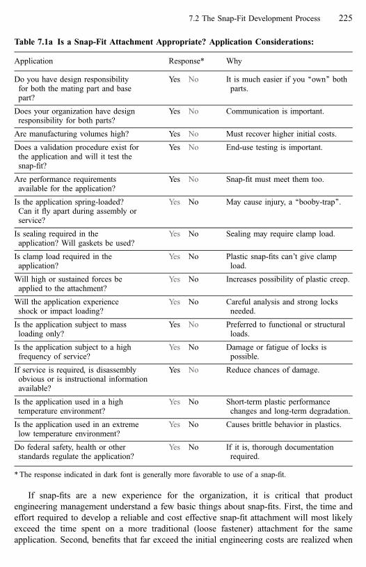
If snap-fits are a new experience for the organization, it is critical that product
engineering management understand a few basic things about snap-fits. First, the time and
effort required to develop a reliable and cost effective snap-fit attachment will most likely
exceed the time spent on a more traditional (loose fastener) attachment for the same
application. Second, benefits that far exceed the initial engineering costs are realized when
Table 7.1a Is a Snap-Fit Attachment Appropriate? Application Considerations:
Application Response* Why
Do you have design responsibilityfor both the mating part and basepart?
Yes No It is much easier if you ‘‘own’’ bothparts.
Does your organization have designresponsibility for both parts?
Yes No Communication is important.
Are manufacturing volumes high? Yes No Must recover higher initial costs.
Does a validation procedure exist forthe application and will it test thesnap-fit?
Yes No End-use testing is important.
Are performance requirementsavailable for the application?
Yes No Snap-fit must meet them too.
Is the application spring-loaded?Can it fly apart during assembly orservice?
Yes No May cause injury, a ‘‘booby-trap’’.
Is sealing required in theapplication? Will gaskets be used?
Yes No Sealing may require clamp load.
Is clamp load required in theapplication?
Yes No Plastic snap-fits can’t give clampload.
Will high or sustained forces beapplied to the attachment?
Yes No Increases possibility of plastic creep.
Will the application experienceshock or impact loading?
Yes No Careful analysis and strong locksneeded.
Is the application subject to massloading only?
Yes No Preferred to functional or structuralloads.
Is the application subject to a highfrequency of service?
Yes No Damage or fatigue of locks ispossible.
If service is required, is disassemblyobvious or is instructional informationavailable?
Yes No Reduce chances of damage.
Is the application used in a hightemperature environment?
Yes No Short-term plastic performancechanges and long-term degradation.
Is the application used in an extremelow temperature environment?
Yes No Causes brittle behavior in plastics.
Do federal safety, health or otherstandards regulate the application?
Yes No If it is, thorough documentationrequired.
* The response indicated in dark font is generally more favorable to use of a snap-fit.
7.2 The Snap-Fit Development Process 225

that design is assembled thousands of times by an operator using no tools and no threaded
fasteners. Third, evaluating the loose vs. snap-fit attachment in terms of the total assembled
cost is important because the piece-cost alone of a part with snap-fits will be higher than that
of a part without snap-fits.
It should be mentioned here that snap-fits are not limited to only plastic-to-plastic
applications. They are also appropriate for many plastic-to-metal applications as well as
some metal-to-metal applications. Details of material properties are, of course, different for
metal parts, but all the rules of snap-fit performance still apply.
Once it is determined that an application is a reasonable candidate for a snap-fit
attachment, the development process can begin. Note, however, that even if the designer
ultimately determines that a snap-fit locking feature can not be used in the application, their
time has not been wasted. The thinking process a designer goes through to create a snap-fit
will result in a better attachment regardless of the final locking method. Selecting an
alternative fastening method will be discussed at the appropriate step in the process.
Table 7.1b Is a Snap-Fit Attachment Appropriate? Component and Material
Considerations:
Components=Materials Response* Why
Is the mating part high mass? Yes No Stronger locks required.
Is there adequate space on the partsfor snap-fit features?
Yes No Space for lock deflectionand protrusions.
Is one or both of the parts to be madeof plastic?
Yes No Easier to do a snap-fit in plastic.
Is the mating part a:Trim, Bezel, Panel, Control moduleCover, Switch, Access door
Yes No These applications are usuallyeasy.
Is either of the parts expensive? Yes No Consider a back-up attachment.
Do the joined materials differsignificantly in rate of thermalexpansion?
Yes No Care needed in developingconstraint.
Are the parts made of ‘‘engineering’’polymers?
Yes No More predictable and higherperformance.
Is the application exposed toultra-violet light?
Yes No Performance degradation ispossible.
Is the plastic exposed to chemicals inthe environment?
Yes No Performance degradation ispossible.
Is high dimensional variation likely? Yes No Care needed in developingconstraint.
Are you a polymers expert or do youhave access to an expert?
Yes No Materials data interpretation.
* The response indicated in dark font is generally more favorable to use of a snap-fit.
226 The Snap-Fit Development Process [Refs. on p. 254]

Applicability of attachment level thinking to other attachment methods is briefly discussed
in Chapter 2.
Because the designer’s choice is frequently between use of a threaded fastener or a snap-
fit, a short list of typical advantages and disadvantages of each method is appropriate.
Because we are discussing plastic, these are written in terms of attaching plastic parts to each
other. Some of the issues would be different for metal to metal attachments.
Table 7.1c Is a Snap-Fit Attachment Appropriate? Information and Organizational
Considerations:
Information=Data Response* Why
Will accurate load information beavailable for analysis?
Yes No For critical applications, a necessity.
Is accurate material property dataavailable for both of the parts to bejoined?
Yes No Needed for accurate analysis.
Will accurate dimensional data beavailable?
Yes No For determining position andcompliance.
Is part=base packaging known orpredictable?
Yes No Access for assembly motions& service.
Do you know the possibility ofmisuse or unexpected loads on theattachment?
Yes No For complete analysis of reliability.
Organizational Response* Why
Is the application a new designrather than a carry-over?
Yes No Sometimes it is easier to start fresh.
Is there enough lead-time toaccommodate possible longerdesign time?
Yes No Generally a longer developmenttime.
Does the organization understandthe trade-off between a piece-costpenalty and assembly savings?
Yes No Support for the effort.
Does the part supplier haveexperience with molding snap-fitapplications?
Yes No Better understanding ofmanufacturing requirements andissues.
Does the purchasing=biddingprocess allow the final supplier tobe the prototype supplier?
Yes No They will learn from prototypedevelopment.
Does the purchasing=biddingprocess allow the supplier toparticipate in design meetings?
Yes No Can give advice duringdevelopment.
* The response indicated in dark font is generally more favorable to use of a snap-fit.
7.2 The Snap-Fit Development Process 227
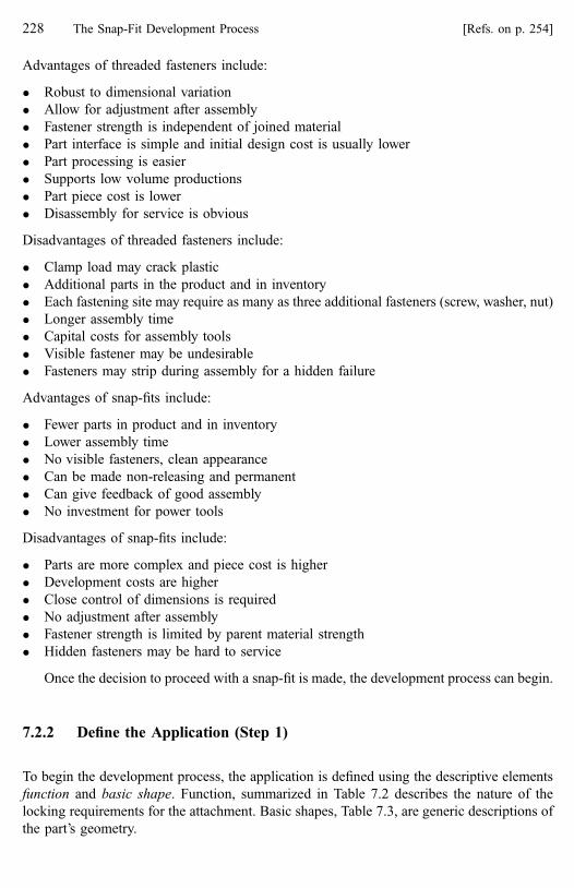
Advantages of threaded fasteners include:
� Robust to dimensional variation
� Allow for adjustment after assembly
� Fastener strength is independent of joined material
� Part interface is simple and initial design cost is usually lower
� Part processing is easier
� Supports low volume productions
� Part piece cost is lower
� Disassembly for service is obvious
Disadvantages of threaded fasteners include:
� Clamp load may crack plastic
� Additional parts in the product and in inventory
� Each fastening site may require as many as three additional fasteners (screw, washer, nut)
� Longer assembly time
� Capital costs for assembly tools
� Visible fastener may be undesirable
� Fasteners may strip during assembly for a hidden failure
Advantages of snap-fits include:
� Fewer parts in product and in inventory
� Lower assembly time
� No visible fasteners, clean appearance
� Can be made non-releasing and permanent
� Can give feedback of good assembly
� No investment for power tools
Disadvantages of snap-fits include:
� Parts are more complex and piece cost is higher
� Development costs are higher
� Close control of dimensions is required
� No adjustment after assembly
� Fastener strength is limited by parent material strength
� Hidden fasteners may be hard to service
Once the decision to proceed with a snap-fit is made, the development process can begin.
7.2.2 Define the Application (Step 1)
To begin the development process, the application is defined using the descriptive elements
function and basic shape. Function, summarized in Table 7.2 describes the nature of the
locking requirements for the attachment. Basic shapes, Table 7.3, are generic descriptions of
the part’s geometry.
228 The Snap-Fit Development Process [Refs. on p. 254]

Defining the application using these attachment level terms will help when design rules
are applied later in the process. Their immediate value, however, is in helping designers
structure a search for ideas as they conduct technical benchmarking in the next step.
In addition to the attachment level elements described above, each application will have
specific performance requirements and in-service conditions which must be defined. Keep in
mind that some of these need not be known at this stage of the process, but they will be
needed eventually. In general, the sooner this information is collected, the better.
Application-specific requirements and conditions can include:
� Material properties.
� Manufacturing limitations and capabilities.
� Load history for the application.
� Thermal history for the application.
� Alignment and appearance requirements.
� Environmental conditions such as chemical and ultra-violet exposure.
At this time, the designer should begin hand-drawn sketches of the application in terms
of its basic shapes. These ‘‘concept sketches’’ will be used to capture ideas and alternatives
throughout the snap-fit concept development process. The designer should also begin
thinking about how a crude model of the application can be constructed.
Table 7.2 Locking Function in the Application
Movable Free movement or controlledAction or
Fixed No movement once latched
Temporary Until final attachment is madePurpose or
Final Snap-fit is the final attachment
Permanent Not intended for releaseRetention or
Non-permanent May be released
Releasing Releases with applied force on the mating partRelease or
Non-releasing Lock is manually deflected for release
Table 7.3 Possible Basic Shape Combinations in the Application
Solid Panel Enclosure Surface Opening Cavity
Mating part Common Common Common Rare Rare LowBase part Common Rare Rare Common Common Common
7.2 The Snap-Fit Development Process 229
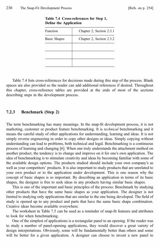
Table 7.4 lists cross-references for decisions made during this step of the process. Blank
spaces are also provided so the reader can add additional references if desired. Throughout
this chapter, cross-reference tables are provided at the ends of most of the sections
describing steps in the development process.
7.2.3 Benchmark (Step 2)
The term benchmarking has many meanings. In the snap-fit development process, it is not
marketing, customer or product feature benchmarking. It is technical benchmarking and it
means the careful study of other applications for understanding, learning and ideas. It is not
simply reverse engineering in order to copy other designs or ideas. Simply copying without
understanding can lead to problems, both technical and legal. Benchmarking is a continuous
process of learning and changing [6]. When one truly understands the attachment method on
another product, the tendency is to change and improve on it for one’s own application. The
idea of benchmarking is to stimulate creativity and ideas by becoming familiar with some of
the available design options. The products studied should include your own company’s as
well as your competitors’ products. It is also important to study products that are unrelated to
your own product or to the application under development. This is one reason why the
concept of basic shapes is so important. By describing an application in terms of its basic
shapes, the designer is free to seek ideas in any products having similar basic shapes.
This is one of the important and basic principles of the process: Benchmark by studying
other products that have the same basic shapes as your application. The designer is not
limited to studying only applications that are similar to the one being developed. The field of
study is opened up to any product and parts that have the same basic shape combination.
Creative ideas become available everywhere.
The worksheet in Table 7.5 can be used as a reminder of snap-fit features and attributes
to look for when benchmarking.
One of the simplest of applications is a rectangular panel to an opening. If the reader was
to study a number of panel-opening applications, they would discover a great variety of
design interpretations. Obviously, some will be fundamentally better than others and some
will be better for a given application. A designer can choose to invent a new panel to
Table 7.4 Cross-references for Step 1,
Define the Application
Function Chapter 2, Section 2.3.1
Basic Shapes Chapter 2, Section 2.3.2
230 The Snap-Fit Development Process [Refs. on p. 254]

opening for their application, or they can study existing applications and select from the best
ideas found as well as the best ideas they generate for themselves. This example also points
out another extremely powerful aspect of defining an application in terms of basic shapes.
That is, ‘‘Why re-invent a new concept?’’ Once an excellent panel-to-opening design concept
has been created, simply adapt it to the application at hand. A designer can establish a library
of good concepts for a variety of basic shape combinations and draw upon that as a reference
for new design.
Benchmarking is easy to ignore, but it is extremely important in driving creativity. As
familiarity with snap-fits increases, attachment level benchmarking will occur naturally
when products are studied.
7.2.3.1 Rules for Benchmarking
� Benchmark on basic shapes and do not limit the search to just one type of product or
application. Many plastic products are available for study including toys, electronics,
Table 7.5 Benchmarking Checklist
For development project: Comments:
Application(s) studied:
Is the application properly constrained?How is it constrained?Are the features effective?
Any evidence of damage?Stress marks?Damage to edges or corners?
How does it feel?Assemble it, is it easy?Shake it, any noises or movement?Drop it to the floor (maybe)
Take it apart.Could a customer take it apart without damage?Are tools required for disassembly?
Look for all enhancements, especially the required ones. Are theyall there?
Are there any shortcomings that need enhancements?
Is it easy to make?No die lockSimple features
How would you rate the application if you had to assemble it 8hours a day?
Poor Fair Good Excellent
How would you rate the application if you were a servicetechnician?
Poor Fair Good Excellent
How would you rate the application if you had to manufacture it? Poor Fair Good Excellent
How would you rate the application if you were a customer? Poor Fair Good Excellent
7.2 The Snap-Fit Development Process 231

small appliances, etc. Most of the time, ideas drawn from several applications will
influence the final design.
� Make it a point to look for enhancements. Enhancements are often added to the product
after the fact because a problem was discovered. When one can recognize enhancement
features and understand what they do, they can either be included in the attachment
design from the start or the condition that made the enhancement necessary can be
avoided.
� Study the constraint features and how constraint and compliance issues are resolved.
Understand why the locks and locators were selected and arranged as they are. Study
how they behave and interact as the parts are brought together through the required
assembly motion.
� Assemble and disassemble the parts. How do they feel? Shake the parts. Do they squeak
and rattle? Are the parts stiff enough? Look at the distribution of constraint features on
the parts. Are there enough to compensate for part flexibility? Flexibility is of particular
concern with large panels as they are usually weak in bending.
� Study the parts for witness marks indicating over-stress or assembly problems. A lighter
color or whitened area at the base of a lock or locator indicates damage. Broken or
damaged edges or corners on parts indicate interference and difficult assembly. These are
clues to strength requirements as well as enhancements that may be needed.
� Cross-references for the benchmarking step are shown in Table 7.6.
7.2.4 Generate Multiple Attachment Concepts (Step 3)
Figure 7.9 showed how the elements of a snap-fit map to the development process. In that
diagram, note that four of the six elements are brought together in the third step. This step is
the most critical of the process because it is where most of the important decisions about the
attachment are made and because it helps to ensure creativity during snap-fit development.
By identifying combinations of allowable engage directions and assembly motions, the
designer can create several fundamentally different attachment concepts rather than mentally
locking themselves into only one idea or just variations on one basic theme. Thomas Edison
said, ‘‘To have a good idea, have lots of them’’. Developing concept alternatives is an
Table 7.6 Cross-references for Step 2, Technical Benchmarking
Constraint Features Chapter 3
Enhancement summary table Chapter 4, Table 4.2Required enhancements Chapter 4, Table 4.3Enhancements and the development process Chapter 4, Table 4.4
232 The Snap-Fit Development Process [Refs. on p. 254]

important enabler for creativity [7]. Constraint features and some enhancements are then
added to each alternative, the concepts are evaluated and one is selected for analysis and
design.
Step 3 need not be long or difficult and it can be conducted as a personal or as a group
brainstorming session. Knowledge gained during careful (attachment level) definition of the
application (Step 1) and benchmarking (Step 2) is now applied as attachment concepts are
generated. Step 3 consists of the five sub-steps shown in Fig. 7.10.
Important: This step is highly recommended as an activity during design for assembly
workshops. The mechanics of using assembly motion alternatives to force generation of
fundamentally different attachment solutions is a critical part of the development process.
7.2.4.1 Select Allowable Engage Directions (Step 3.1)
Once the application’s design constraints and shapes are defined, engage direction is
generally the first decision made in the snap-fit design process. (The reader should
understand that engage direction is not the same as assembly motion.) Careful selection of
an engage direction is important because it is associated with a separation direction that, in
turn, determines locking feature orientation. In most snap-fit applications, the separation
direction is opposite the engage direction. In other words, the lock pair(s) disengage or
separate in the opposite direction from which they engage. The basic rules for selecting
allowable engage directions are:
� Engage directions must be compatible with the basic shapes.
� They must be compatible with access for assembly, service and usage. Also consider if
any other parts added later would interfere with service.
� They must be ergonomically friendly if the parts will be assembled by human operators.
Step 3, Generatemultiple concepts
Selectallowableengage
directions:ED1 - EDn
Select andarrange
constraint pairsusing the best
ED/AMcombinations.
Select all possibleassembly motionsfor each engage
direction:ED1 AM1 -EDn AMn
Addenhancement
features tobest ED/AM
combinations.
Select bestconcept for
analysisand detailed
design.
"To have a good idea, have lots of them ."- Thomas Edison
"To have a good idea, have lots of them"- Thomas Edison
Figure 7.10 Details of the generate multiple concepts step
7.2 The Snap-Fit Development Process 233

� If intended for automatic assembly, consider the impact of access and motion complexity
on capital equipment costs.
� There should be no significant forces acting in the separation direction.
The last point deserves additional comment. Any forces acting in the separation direction
will be acting directly against the lock features, trying to pull the components apart. Because
the lock features are inherently weak, this is always an undesirable situation. (However, we
have seen that there are ways to make the lock feature stronger so they can carry some
forces.) How does one know when the separation forces are significant? Analysis of the lock
feature performance will give an indication, but it is a good design practice to simply avoid
any forces in the separation direction if possible. Keep in mind also that the significance of a
force may depend on more than just its magnitude, duration and frequency are also
important considerations.
Forces across the snap-fit interface are one of the application specific requirements that
the designer should know. Early in the development process, information on the magnitude
of the forces may not be available or force information may be based on estimates with more
exact data to come later. At this stage of development, it is not necessary to know the exact
magnitudes of the forces. It is important to know the direction and a relative magnitude of
each force. Most of the time, engage direction decisions can be made with this information.
Some applications will have only one allowable engage direction, others will have more
than one. All allowable engage and separation directions should be represented by vectors
on a convenient coordinate system selected by the designer. This coordinate system can now
be added to the concept sketches begun in Step 1. The engage and separation vectors are also
added to the sketches now. Some applications will have more than one possible set of engage
and separation directions and all allowable directions should be identified. In Fig. 7.10, they
are identified as ED1, ED2, etc.
7.2.4.2 Identify All Possible Assembly Motions (Step 3.2)
Recall that five simple assembly motions: push, slide, tip, spin and pivot are used to describe
final mating part motion as the lock(s) engage. Each assembly motion will allow certain
constraint feature configurations and preclude others. In Fig. 7.10, assembly motion is
identified as AM1, AM2, etc.
Given the allowable engage directions determined in Step 3.1 and the basic shapes, the
designer will find that only some of the five assembly motions are feasible. Identify all
possible assembly motions for each allowable engage direction. Again, certain application
conditions may render some of these combinations undesirable although they may be
feasible. Eliminate those combinations from consideration. By the end of this step, one has
identified some ‘‘best’’ combinations. The application conditions that drive assembly motion
decisions include many of the same conditions that drive engage direction decisions:
� Assembly motions must be compatible with the engage direction.
� They must be compatible with the basic shapes.
� They must be compatible with access for assembly, service and usage. Also consider if
any other parts added later would interfere with service.
� They must be ergonomically friendly if the parts will be assembled by human operators.
234 The Snap-Fit Development Process [Refs. on p. 254]

� If intended for automatic assembly, consider the impact of access and motion complexity
capital equipment costs.
Figure 7.11 shows how different assembly motions will force different interface designs
for the same solid to surface application. Note that, by definition, the assembly motion is the
final motion made to engage the locking feature(s). For a push motion, Fig. 7.11a, all initial
engagement must occur with lock features. In contrast, Fig. 7.11b shows how, for a tip
assembly motion the lug(s) must be engaged first before the tip motion can begin. In Fig.
7.11c, a slide motion, the mating part must first be placed against the surface so that the lugs
are aligned with the edges they will engage.
Any additional motions required to bring the mating part to the base part are not
considered at this time because, although they may be affected by or related to the final
assembly motion, they do not drive the constraint feature decisions.
(a) For a solid to surface attachment,a push motion forces the use ofdeflecting features at certainsites
(b) Another assembly motion (tip)forces the use of different features atsome sites
(c) A third assembly motion (slide) also forces the use of different features
Figure 7.11 How different assembly motions force creation of fundamentally different attachingoptions
7.2 The Snap-Fit Development Process 235

Rules for Selecting an Assembly Motion
� In general, the push assembly motion will likely result in a weaker attachment because
more degrees of motion must be removed by the (generally weaker) lock features. The
other assembly motions allow more degrees of motion to be removed by the (stronger)
locators and are generally preferred.
� The tip motion has certain advantages over some of the others. The first locator pair,
once engaged, stabilizes the mating part relative to the base part for easier engagement of
the remaining constraint pairs. The tip motion also minimizes potential for simultaneous
engagement of constraint features.
� Disadvantages of the tip motion are that the rotational movement may require more
space than is available for assembly and if excessive rotation is involved, assembly
operators may be subject to cumulative trauma injury.
� In general, the tip and slide assembly motions are preferred over the push motion.
However, at this stage of the process, the intention is to use assembly motion alternatives
to generate ideas. All feasible assembly motions should be considered at this time.
It is desirable to have at least three ED=AM combinations at the end of this step although
in some applications this will not be possible. At this time, the designer should make enough
copies of the original concept sketch so that constraint pairs and eventually enhancements
can be sketched onto each available ED=AM combination.
Table 7.7 shows the cross-references for the Engage Direction and Assembly Motion
steps.
7.2.4.3 Engage Directions, Assembly Motions and Worker Ergonomics
The subject of assembly operator ergonomics is far beyond the scope of this book, but it
deserves mention at the awareness level. Readers are encouraged to seek out appropriate
application specific information to ensure their final design is ‘‘operator friendly’’.
Information related to maximum allowable assembly forces, assembly direction, workpiece
height, cycle times and operator motions is particularly applicable to snap-fit design.
Simplicity of design and the complexity of decisions required during assembly can impact
mental fatigue, number of mistakes and product quality.
Table 7.7 Cross-references for Step 3.1 and
Step 3.2, Engage Directions and Assembly
Motions
Engage Direction Chapter 2, Section 2.3.3
Assembly Motion Chapter 2, Section 2.3.4
236 The Snap-Fit Development Process [Refs. on p. 254]

Some very general rules for ergonomic design include the following: [8, 9, 10]
� Product designs having low cycle times repeated over extended periods of time should
have low assembly forces.
� The operator should not be required to strike or pound (as with the palm of the hand) the
mating part to cause it to snap to the base part. Any impact is undesirable.
� Designs that force the operator into an unnatural body position or force an unnatural
arm, shoulder, wrist or hand position while applying assembly force should be avoided.
� Avoid designs that require continuous, rapid and repetitive application of force.
� The areas of a part where the operator must apply assembly force should distribute
pressure over a sufficient area of the finger or hand. Pushing against edges, corners or
points should be avoided.
� Assembly of parts while wearing gloves can have negative ergonomic effects as well as
process efficiency effects. If gloves must be worn, the part design must reflect that
requirement.
� Part designs that favor right-handed over left-handed workers should be avoided.
Specific work-related musculoskeletal disorders (WMSDs) [10] that can be related to
snap-fit assembly include: carpal tunnel syndrome, epicondylitis (tennis elbow), neck
tension syndrome, shoulder tendonitis, tendonitis, ulnar artery aneurysm, ulnar nerve
entrapment and DeQuervain’s syndrome.
7.2.4.4 Select and Arrange Constraint Pairs (Step 3.3)
Constraint features are lock and locator pairs that prevent relative movement between parts.
Ideas gained during benchmarking will now help the designer select the best constraint
features for the application. The strategy of identifying several engage direction=assembly
motion combinations will now pay off. As constraint features are selected and arranged,
basic shape and assembly motion interactions will force the use of different constraint
feature styles for each possible ED=AM combination. This drives creativity by forcing
development of fundamentally different attachment concepts rather than just variations on
one theme.
To this point, the designer should have been working with hand-drawn concept sketches.
(Leave that computer and the design programs alone!) It is now time to create a 3-D model
of the application. Again, as with the concept sketch, the purpose is to invoke spatial
reasoning skills and creativity. The model at this stage of the process need not (in fact, it can
not be) very detailed or even accurate. The most important thing is to get something in three
dimensions that can be held and manipulated in space. While making constraint features
decisions, use the model(s) to visualize the interactions of the mating and base parts under
the different ED=AM combinations. Also use the model to visualize how the interface will
react to input forces.
Models can be very useful as a visual device when explaining or trying to sell an idea to
others. The highly spatial and sometimes complex nature of snap-fits can make them
difficult to explain with words alone or 2-D drawings. The designer willing to provide a
model has a better chance of getting their point across.
7.2 The Snap-Fit Development Process 237
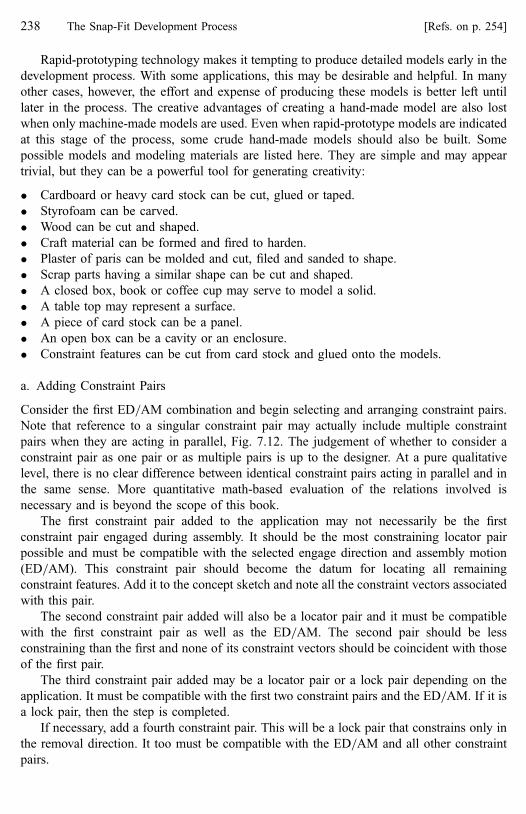
Rapid-prototyping technology makes it tempting to produce detailed models early in the
development process. With some applications, this may be desirable and helpful. In many
other cases, however, the effort and expense of producing these models is better left until
later in the process. The creative advantages of creating a hand-made model are also lost
when only machine-made models are used. Even when rapid-prototype models are indicated
at this stage of the process, some crude hand-made models should also be built. Some
possible models and modeling materials are listed here. They are simple and may appear
trivial, but they can be a powerful tool for generating creativity:
� Cardboard or heavy card stock can be cut, glued or taped.
� Styrofoam can be carved.
� Wood can be cut and shaped.
� Craft material can be formed and fired to harden.
� Plaster of paris can be molded and cut, filed and sanded to shape.
� Scrap parts having a similar shape can be cut and shaped.
� A closed box, book or coffee cup may serve to model a solid.
� A table top may represent a surface.
� A piece of card stock can be a panel.
� An open box can be a cavity or an enclosure.
� Constraint features can be cut from card stock and glued onto the models.
a. Adding Constraint Pairs
Consider the first ED=AM combination and begin selecting and arranging constraint pairs.
Note that reference to a singular constraint pair may actually include multiple constraint
pairs when they are acting in parallel, Fig. 7.12. The judgement of whether to consider a
constraint pair as one pair or as multiple pairs is up to the designer. At a pure qualitative
level, there is no clear difference between identical constraint pairs acting in parallel and in
the same sense. More quantitative math-based evaluation of the relations involved is
necessary and is beyond the scope of this book.
The first constraint pair added to the application may not necessarily be the first
constraint pair engaged during assembly. It should be the most constraining locator pair
possible and must be compatible with the selected engage direction and assembly motion
(ED=AM). This constraint pair should become the datum for locating all remaining
constraint features. Add it to the concept sketch and note all the constraint vectors associated
with this pair.
The second constraint pair added will also be a locator pair and it must be compatible
with the first constraint pair as well as the ED=AM. The second pair should be less
constraining than the first and none of its constraint vectors should be coincident with those
of the first pair.
The third constraint pair added may be a locator pair or a lock pair depending on the
application. It must be compatible with the first two constraint pairs and the ED=AM. If it is
a lock pair, then the step is completed.
If necessary, add a fourth constraint pair. This will be a lock pair that constrains only in
the removal direction. It too must be compatible with the ED=AM and all other constraint
pairs.
238 The Snap-Fit Development Process [Refs. on p. 254]

Repeat the process for all remaining ED=AM combinations.
Some designers have an intuitive feeling for constraint and will quickly understand the
process. For others, some practice is required in order to reach that understanding of
constraint. A matrix of constraint pairs and constraint directions as shown in Table 7.8 can
serve as a valuable learning tool. The matrix is also useful when explaining the rational
behind a snap-fit design to someone else. With constraint pairs listed vertically and the 12
DOM listed across the top, the matrix can serve as a checklist for recording DOM as they
accumulate with the addition of constraint pairs and for verifying that neither over
nor under-constraint has occurred. The constraint matrix is discussed in more detail in
Chapter 5.
Decisions about placing a given constraint feature on the base part or the mating part are
driven by many considerations. Manufacturing considerations, material strength, basic shape
and assembly motion are the most common. Another may be the relative value of the parts
and the chances of feature (particularly lock) breakage. Design the application so that if a
feature does break, (improper disassembly, overload, etc), the part likely to break is easily
replaced, inexpensive, easily serviced or repaired.
b. Rules for Selecting and Arranging Constraint Pairs
Many of these rules were introduced along with constraint features in Chapter 3. Refer back
to that chapter for details.
(a) Locators
The lines of action and the net effect on constraint are the same in both cases
(b) Locks
The lines of action and the net effect on constraint are the same in both cases
Figure 7.12 Multiple vs. single constraint features
7.2 The Snap-Fit Development Process 239

Table 7.8 Constraint Worksheet Original2
40
Th
eS
nap
-Fit
Dev
elop
men
tP
rocess
[Refs.
on
p.
25
4]

� Lock pairs should constrain in as few degrees of motion (DOM) as possible and locator
pairs in as many DOM as possible. Ideally, the lock pair should constrain only in the one
DOM associated with part separation.
� Generally, the more degrees of motion removed with locators, the stronger the
attachment.
� A tip or slide assembly motion is preferred over the push motion because more degrees
of motion are removed with locators and because of ease of assembly.
� The application should not be over-constrained due to redundant constraint pairs.
� Over-constraint due to opposing constraint pairs is undesirable but sometimes necessary.
� Where constraint pairs oppose each other (two constraint pairs with collinear strength
vectors of opposite sense), placing the pairs as close to each other as possible will
minimize tolerance effects and the potential for opposing internal forces within the
constraint system.
� Where constraint pairs create a couple, (parallel strength vectors of opposite sense) they
should be placed as far apart as possible for mechanical advantage and reduced
sensitivity to tolerances.
� Where constraint pairs have parallel strength vectors (of either the same or of opposite
sense) they should be placed as far apart as possible for maximum mechanical advantage
and reduced sensitivity to dimensional variation.
� Applications should not be under-constrained. Under-constraint occurs when no
constraint pairs provide strength in one or more translational degrees of motion or
when a constraint couple is ineffective in removing rotational constraint.
� In a fixed application, the mating part must be constrained to the base part in exactly 12
DOM. An exception is certain functional attachments where free movement is allowed in
some degrees of motion.
� Locking features should not carry high forces or sustained forces, particularly in the
separation direction or in bending.
� Compliance should generally occur within a constraint pair rather than between pairs.
� The lock retention face can be used to take up some tolerance. A slight angle on the
retention face of a (90� non-releasing) hook will absorb tolerance without affecting
retention. A contoured face can ensure maximum retention angle at any level of hook
deflection.
� Select and orient constraint pairs whenever possible to avoid a die-lock condition.
After adding constraint features to the concept sketches, the designer may also wish to
build them into the 3-D models. Rapid prototype models may again be considered. Including
the locator features on models is useful because their presence allows one to evaluate ease of
assembly and some aspects of constraint. In many cases however, there is little or no value in
including the (flexible) locking features on the models. Sometimes materials used in rapid-
prototyping are brittle and the flexible features are soon broken off. It is possible to make
locking features out of flexible plastics and attach them to the models with screws or
adhesives. This can be useful in some cases although these locks will not represent realistic
lock feature performance.
Table 7.9 is the cross-reference for selecting constraint features.
7.2 The Snap-Fit Development Process 241

7.2.4.5 Add Some Enhancement Features (Step 3.4)
For each concept alternative, decide which enhancements are needed. Enhancements are
either physical features or attributes of constraint features or of the parts themselves. At this
step in the development process, one can often predict the need for some enhancements
depending on the nature of the application. Guides, pilots, visual, assists and guards are
enhancements that can usually be added to the attachment concept now, if the application
requires them. The remaining enhancements are normally added later when a detailed design
is established.
Table 7.10 is the cross-reference for adding some enhancement features.
7.2.4.6 Select the Best Concept for Feature Analysis and Detailed Design (Step 3.5)
To this point, the development process has been both a structured and a creative process. The
result is several fundamentally different and technically sound snap-fit attachment concepts.
Each concept has constraint features arranged to provide proper mating part to base part
constraint. Some enhancement features have also been added to each concept.
At this point, each concept should be reviewed by appropriate stakeholders. Likely
stakeholders include the product engineer(s) and designer(s) for both the mating and base
parts; cost analysts, purchasing agents, materials experts, part manufacturers and
manufacturing, assembly and process engineers. The best concept is selected to be carried
forward into design and recommendations for improvements may also be made. The other
concepts, if judged feasible, can be ranked in order of preference and kept available should
the selected design become unacceptable as the program proceeds. The models and sketches
created to this point should be available for this concept review and can be valuable tools for
Table 7.9 Cross-references for Step 3.3, Select
Constraint Pairs
Constraint introduction Chapter 2, Section 2.2.2
Constraint concepts Chapter 5, Section 5.1.2
Locator feature styles Chapter 3, Section 3.2.1
Locator pairs Chapter 3, Section 3.2.2
Lock feature styles Chapter 3, Section 3.3.1
Design rules Chapter 3, Section 3.4.2
242 The Snap-Fit Development Process [Refs. on p. 254]

explaining the details of each design. Table 7.11 is a worksheet for comparing alternatives
when selecting the best concept.
Whenever possible, plan for the prototype supplier to also be the production supplier.
Plastic part tooling and processing requires a thorough understanding of the application.
Supplier input during the initial design can help ensure a functional design that can be
reliably produced. Single sourcing of parts may be desirable for the same reasons. These
kinds of decisions are often made based on purchasing and organizational procedures, but
the designer may be able to present a solid business case for a single knowledgeable
supplier.
This concludes the concept development phase of the process. We exit Step 3 with a
fundamentally sound attachment concept ready for snap-fit feature analysis and detailed
design. We now move into the more familiar and traditional area of feature analysis and
detailed design.
7.2.5 Feature Analysis and Design (Step 4)
To this point, we have been working with concepts and ideas, not dimensions or details. Step
4 is the detailed design step. The objective is to evaluate feature performance and determine
dimensions for:
� Acceptable installation and removal effort.
� Retention and load carrying strength.
� Acceptable stress and strain levels during assembly and release removal deflection.
� Acceptable stress and strain levels under applied loads.
� Squeak and rattle resistance.
Table 7.10 Cross-references for Step 3.4, Add Some Enhancement
Features
Enhancements Chapter 4
Enhancements summary Chapter 4, Table 4.2
Enhancement requirements Chapter 4, Table 4.3
Enhancements and the development process Chapter 4, Table 4.4
Design rules Chapter 4, Section 4.6.2
7.2 The Snap-Fit Development Process 243
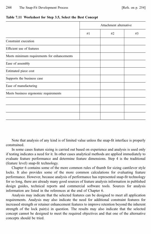
Note that analysis of any kind is of limited value unless the snap-fit interface is properly
constrained.
In some cases feature sizing is carried out based on experience and analysis is used only
if testing indicates a need for it. In other cases analytical methods are applied immediately to
evaluate feature performance and determine feature dimensions. Step 4 is the traditional
(feature level) snap-fit technology.
Chapter 6 contains some of the more common rules of thumb for sizing cantilever style
locks. It also provides some of the more common calculations for evaluating feature
performance. However, because analysis of performance has represented snap-fit technology
for so long, there are already many good sources of feature analysis information in published
design guides, technical reports and commercial software tools. Sources for analysis
information are listed in the references at the end of Chapter 6.
Analysis may indicate that the selected features can be designed to meet all application
requirements. Analysis may also indicate the need for additional constraint features for
increased strength or retainer enhancement features to improve retention beyond the inherent
strength of the lock pair(s) in question. The results may also indicate that the selected
concept cannot be designed to meet the required objectives and that one of the alternative
concepts should be tried.
Table 7.11 Worksheet for Step 3.5, Select the Best Concept
Attachment alternative
#1 #2 #3
Constraint execution
Efficient use of features
Meets minimum requirements for enhancements
Ease of assembly
Estimated piece cost
Supports the business case
Ease of manufacturing
Meets business ergonomic requirements
244 The Snap-Fit Development Process [Refs. on p. 254]

Recall that the purpose of the first three steps of the process is to create a fundamentally
sound attachment concept. A concept can be sound and yet fail to meet one or more of the
objectives because of a combination of material performance limitations and conflicting
performance requirements. For example, a high retention strength requirement can be in
conflict with a low insertion force requirement or the material properties will not support the
required assembly performance. Why then should we waste our time creating a
fundamentally sound attachment if it might not work? Because the fundamentally sound
concept has the best chances of working.
Additional enhancements should be added at this time if indicated. In all applications,
the manufacturing enhancements (process-friendly and fine-tuning) should be included in
the final design.
7.2.5.1 Lock Alternatives
The purpose of a snap-fit is to use integral lock features. But, the feature analysis may
indicate that any integral lock cannot be made to work in the application and reality is simply
that snap-fits will not work everywhere. All is not lost, however, because other locking
methods are often available for use in place of the integral lock. If the snap-fit design process
has been followed, a properly constrained attachment with a number of locating features now
exists. The final decision about lock dimensions is not made until this point. When we recall
that lock features are the last constraint features added to the design and the last features
engaged during assembly, we see that, for most applications, replacing an integral lock with
an alternative locking feature can be relatively simple.
Details of the fastening methods suggested as alternatives to integral locks are beyond
the scope of this book. The purpose here is simply to introduce the idea of alternatives to the
integral lock and give the reader a starting point for further investigation.
Some of the lock alternatives described here lend themselves to automatic assembly to
the parent component. In that case, they can be installed before final assembly and, as far as
assembly operators are concerned, they are integral locks and the assembly labor savings
apply just as with integral locks. Even screws can sometimes be pre-assembled to plastic
parts so the operator does not need to handle loose fasteners. The mechanism used to capture
the screw in the part can be a snap-fit feature.
Recall also that provisions for back-up fastener(s) can be designed into an application as
a performance enhancement.
Any separate fastening method will add some cost to the attachment, but by following
the process and designing for proper constraint using locators, the number of loose fasteners
is minimized as is the associated cost impact. Three common lock alternatives, screws, push-
in fasteners and spring clips, are discussed here. Other attachment methods like hook-loop
fasteners and double-back tape may also be considered as alternatives to an integral lock
feature.
a. Screws
In place of an integral lock, a loose threaded fastener can be used. If locators are identified
and the attachment is properly constrained, usage of loose fasteners will be minimized and
the design will be optimized for design for assembly.
7.2 The Snap-Fit Development Process 245

If a screw is to be used, the first decision to be made is about the internal thread. Will it
be made directly in the plastic material or will it also be a separate part? If the threads will be
made directly in the plastic, the method of making the threads must be considered.
Do not use sheet metal or machine thread fasteners for tightening directly into plastic.
Use fasteners that are designed specifically for tightening into plastic. These screws
generally use various combinations of special thread form, thread pitch or cross-section
shape to reduce the stresses produced in the plastic as material is displaced to form the
threads. Other styles have cutting flutes that cut the plastic away to form the thread. Selection
of a thread forming or a thread cutting screw should be based on the application’s tolerance
for chips (created if thread cutting screws are used) and the properties (hardness=toughness
are most important) of the material in which threads are to be created.
Some suppliers of fasteners for use in plastic are listed in the cross-reference, Table 7.12
at the end of this chapter, but this list is far from all-inclusive. Running screws directly into
plastics also requires careful design of the area of the part intended to accept the screw.
Running a screw into a thin wall is generally undesirable and a boss should be added for
additional length of thread engagement. Boss design is beyond the scope of this book but
boss design guidelines are available from the resin suppliers and usually from the screw
manufacturers as well. A few general considerations for using screws in plastics are:
� A boss will tend to cause a sink mark on the opposite side of the wall on which it sits.
Choose the depth of core pin and boss wall thickness carefully.
Table 7.12 Cross-references for Step 4, Feature Analysis and Design
Lock feature rules of thumb Chapter 6, Section 6.3
Analytical methods Chapter 6, Section 6.9
Designing plastic parts for assembly Tres, Paul [11]
Plastic part design for injection molding Malloy, Robert [4]
Screws for use in plastics Camcar-Textron, Rockford, IllinoisITW—Shakeproof, Elgin, Illinois
Plastic push-in fasteners ITW—Deltar, Frankfort, IllinoisTRW Fastening Systems, Farmington Hills, Michigan
Metal spring clips California Industrial Products, Livonia, MichiganEaton Corp. Cleveland, Ohio
246 The Snap-Fit Development Process [Refs. on p. 254]

� A boss can create high residual stresses and=or voids at its base which will weaken the
area.
� If the screw enters the free end of the boss rather than at the base, allow for a stress relief
area at the end of the boss by recessing the pilot hole slightly. This is easy to do because
the hex removal feature at the base of the pilot hole core pin can provide this recess.
� Screws with countersunk heads should not be used against plastic because the wedging
action of the screw head will tend to crack the material.
� Screws coated with oil or having an oil-based finish should not be used in plastic
because some plastics degrade in the presence of oil.
� Distribute the pressure under the head of the screw over a wide area with a captive
washer on the screw.
� If high speed tightening of the screw is the assembly method, a captive washer is
recommended for screws tightened against plastic. Heat build-up due to friction under
the head of the screw may melt the plastic if a washer is not present.
� High speed tightening of the screw may also cause heat build-up in the plastic material to
the point that the properties of the plastic in the area of the threads will degrade resulting
in very weak threads. Limiting the tightening speed may be necessary.
� Screws will develop clamp load. Plastics tend to creep and a high clamp load may result
in long-term cracking of the plastic under the fastener and=or in the boss.
� Over-tightening and stripping of the plastic threads is possible. This is a hidden failure
and it may leave the assembly plant undetected.
� If screws are to be removed and reassembled into the plastic multiple times for repair,
cumulative damage to the plastic threads is a possibility.
� If the application does not permit perfect alignment of the screw to the pilot hole for
assembly, then cracking of the boss during rundown is likely.
� The driving impression style on the screw head must be selected for screw stability
during rundown. The driver bit must be selected for compatibility with the driving
impression.
When the feasibility of threading directly into plastic is questionable, another method of
attaching to plastics with threaded fasteners involves use of molded in or pressed in metal
inserts having machine threads. These inserts add cost to the process and to the parts but
provide higher thread strength. They also provide a solution where the extra thickness of a
boss is not possible and the screw must run into a wall.
Screws can also be used with separate internal threads like machine thread nuts and
single or multiple thread impression nuts and clips. As with inserts, this eliminates the
considerations associated with threading directly into plastic bosses, but the clamp load
considerations still apply.
Sometimes loose fasteners can be captured in the plastic parts prior to final assembly.
This eliminates operator handling and saves time. Some methods for capturing screws in
parts are shown in Fig. 7.13.
References [4] and [12] provide good discussions of many of the issues associated with
loose fasteners in plastics.
7.2 The Snap-Fit Development Process 247

b. Push-In Fasteners
We do not tend to think of push-in fasteners as snap-fits, but in many ways they are. Push-in
fasteners are usually spring steel or plastic, Fig. 7.14, and they involve integral feature
deflection and return for interference, just like a snap-fit lock. Like snap-fits, push-in
fasteners do not generate significant clamp load. The common one-piece style push-in style
fasteners do not decouple assembly and retention but the two-piece fasteners do. (See
Chapter 5.)
Sometimes, push-in fasteners can be installed automatically in the part before reaching
final assembly. In this case, as far as the assembly operator is concerned, they are integral
snap-fits. As a designer, keep in mind that all the rules for good snap-fit design will apply to
these applications. Other push-in fasteners are installed by the operator and will add cost as a
separate part in the assembly process. Ergonomic limits on push-in forces apply to these
fasteners when they are hand-installed. Removal for service can also be an issue. The
Screw held in place bytraps
Screw held in placeby hooks
Screw threaded throughclearance hole
Figure 7.13 Threaded fasteners captured in plastic parts
(a) One-piece push-infasteners
(b) Two-piece plasticpush-in fastener
Plastic ribbedor “fir-tree” style
Plastic“rosebud” style
Spring steelclip
Beforeinstallation
Afterinstallation
Joining twopanels
Figure 7.14 Examples of push-in fastener alternatives to integral lock features
248 The Snap-Fit Development Process [Refs. on p. 254]
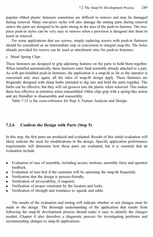
popular ribbed plastic fasteners sometimes are difficult to remove and may be damaged
during removal. Many one-piece styles will also damage the mating parts during removal
unless the parts are designed to be quite strong in the area of the push-in fastener. The two-
piece push-in styles can be very easy to remove when a provision is designed into them to
assist in removal.
For some applications that use screws, simply replacing screws with push-in fasteners
should be considered as an intermediate step in conversion to integral snap-fits. The holes
already provided for screws can be used as attachment sites for push-in fasteners.
c. Metal Spring Clips
These fasteners are designed to grip adjoining features on the parts to hold them together.
When installed automatically, these fasteners enter final assembly already attached to a part.
As with pre-installed push-in fasteners, the application is a snap-fit as far as the operator is
concerned and, once again, all the rules of snap-fit design apply. These fasteners are
frequently designed with sharp barbs intended to dig into and hold the parts together. The
barbs can be effective, but they will cut grooves into the plastic when removed. This makes
them less effective in retention when reassembled. Other clips grip with a spring-like action
and are friendlier to disassembly and reassembly.
Table 7.12 is the cross-reference for Step 4, Feature Analysis and Design.
7.2.6 Confirm the Design with Parts (Step 5)
In this step, the first parts are produced and evaluated. Results of this initial evaluation will
likely indicate the need for modifications to the design. Specific application performance
requirements will determine how these parts are evaluated, but it is essential that an
evaluation include:
� Evaluation of ease of assembly, including access, motions, assembly force and operator
feedback.
� Evaluation of user-feel if the customer will be operating the snap-fit frequently.
� Verification that the design is process-friendly.
� Verification of serviceability, if required.
� Verification of proper constraint by the locators and locks.
� Verification of strength and resistance to squeak and rattle.
The results of the evaluation and testing will indicate whether or not changes must be
made to the design. The thorough understanding of the application that results from
following the snap-fit development process should make it easy to identify the changes
needed. Chapter 8 also describes a diagnostic process for investigating problems and
recommending changes to snap-fit applications.
7.2 The Snap-Fit Development Process 249

7.2.7 Fine-Tune the Design (Step 6)
In this step, changes indicated by evaluating first parts are made. Any necessary mold
changes will be much easier if fine-tuning enhancements (Chapter 4) have been included in
the design. Other enhancements that now appear to be necessary can be added. Of course,
several cycles of design confirmation with parts and fine-tuning may occur before the part
attachments are acceptable. One objective of the snap-fit development process is to reduce
the design iterations required to get good parts.
7.2.8 Snap-Fit Application Completed (Step 7)
The attachment level development process is now completed. As a final review, the
evaluation worksheet in Table 7.13 can be used to confirm that all the important aspects of
attachment level snap-fit development have been considered.
7.3 Summary
This chapter explained the snap-fit development process in detail. It also provides cross-
references to other areas of the book and other sources of information related to the process.
The snap-fit development process must be conceptual and creative before it is analytic. By
design, the attachment level construct is rule-based to support learning and practical
application of profound knowledge to snap-fits. The step-by-step development process
described here leads the designer to apply those rules. A snap-fit designer will experience
improved creativity and spatial reasoning when developing attachment concepts. As the
process is followed, it becomes second nature as users grow in their understanding of snap-
fits.
7.3.1 Important Points in Chapter 7
� The snap-fit development process is highly compatible with and supports design for
assembly (DFA) principles. Specific aspects of this process should be included in the
design for assembly thought process and in DFA workshops. The concepts of generic
basic shapes and assembly motions as well as the use of assembly motion to drive
interface design alternatives are particularly important and applicable to design for
assembly [13].
250 The Snap-Fit Development Process [Refs. on p. 254]

Table 7.13 Final Snap-Fit Evaluation
Basic shapes Mating part is Solid Panel Enclosure CavityOpening
Base part is Solid Enclosure Cavity OpeningFunction Action is Fixed Moveable (free=controlled)
Attachment type is Temporary FinalRetention is Permanent Non-permanentLock type is Releasing Non-releasing
Assembly motion Preferred Push Slide Tip Twist Pivot*
Strength=forces Requirements=directionsidentified?
Yes* No
Alignment Requirements=directionsidentified?
Yes No
Packaging Operator access Easy DifficultClearance for part movements Yes No
Material Properties=families identified Yes No
Geometry Dimensions and tolerancesidentified
Yes No
Separation direction Any significant forces? Yes No
If significant forcesin separation direction
Retainer enhancements added? Yes No
Trap locks used? Yes NoDecoupling considered? Yes No
Locators Used as guides? Yes NoUsed as pilots? Yes No
Usage is maximized? Yes NoHave clearance enhancements? Yes No
Well distributed onpanels to prevent squeak
and rattle?
Yes No
Critical pair selected asdatum for others?
Yes No
Simultaneous engagementof multiple locator
features?
Yes No
Locks Usage is minimized? Yes NoCarrying high orsustained forces?
Yes No
Well distributed on panelsto prevent squeak
and rattle?
Yes No
Simultaneous engagement ofmultiple no features?
Yes No
Simple shapes? Yes NoEngage locatorsin the lock pair?
Yes No
Only constrain in theseparation direction?
Yes No
Benchmarking Conducted on Basic shapesSimilar applicationsBoth
Where appropriate, preferred choices are in bold font
7.3 Summary 251

Table 7.13 (Continued)
Constraint Proper constraint verified? Yes* No
If over-constrained In opposition? Yes NoRedundant features? Yes No
Compatibility Between basic shapesand assembly motion?
Yes No
Between locator pairsand assembly motion?
Yes No
Between lock pairsand assembly motion?
Yes No
Assembly and disassemblymotions are the same?
Yes No
Required enhancements Guides? Yes NoOperator feedback? Yes No
Clearance? Yes NoProcess friendly? Yes No
Desirable enhancements Compliance? Yes NoFine-tuning? Yes No
Other enhancements(depends on application)
Pilots Yes No
Guards Yes NoUser feel? Yes No
Visuals? Yes NoAssists? Yes No
Retainers? Yes NoBack-up locks? Yes No
Operator feedback Preferred Tactile Audible Visual Multiple
Feature design (dependson application)
Based on analysis? Yes No
Rules of thumb? Yes No
Evaluation of first parts Assembly interference? Yes NoAcceptable assembly force? Yes No
Feature damage during assembly? Yes NoOperator feedback? Yes No
Compatibility and constraint? Yes NoAttachment durability? Yes No
User feel? Yes NoPart and feature consistency? Yes No
Fine-tuning Location? At=opposite critical alignment sites.
Compliance Location? Within=between constraint pairs.At=opposite critical alignment sites.At=opposite critical load bearing sites.
Parts Sharp corners? Yes NoThick sections? Yes No
Sudden section changes? Yes No
Where appropriate, preferred choices are in bold font.
252 The Snap-Fit Development Process [Refs. on p. 254]

Execution Why
Use this checklist for early screening of part proposals. The objective is to understand the design’s potential for creating a reliable, durable and cost-effective attachment that can be consistently manufactured and assembled to meet all product requirements. doo
G
riaF
rooP
A/N
y lbm es s
Afoesa
E
Cos
tecei
P
ytilibaeciv reS
ytilibaruD/yt ilib aile
R
yti lauQtcud or
P
Constraint in 12 DOM (less if a moveable application) • • •Sufficiently strong lock and locator features • •
Feature, basic shape and assembly motion compatibility • • • •Guide and clearance enhancements •
Operator feedback • •Process-friendly • •
Proper radii called out at all critical locations •
snoitacilppAlla
nideriuqe
R
Fine-tuning enhancements • •Normal (commercial) rather than fine/close tolerances •
Design is robust to potential material changes • • •
llani
derreferP
snoitacilppA
Other enhancements as needed • • • • •High (customer) perceived quality2 •
noitacilppA
cificepS
Short grip length - A lock feature having beam length less than ~5x its thickness. Cantilever hook lockstypically do not work well in this situation. Use a lock style with higher decoupling capability.
Brittle material - Will be much more sensitive to stress concentrations, small radii, assembly strain, over-deflection and short grip lengths.
Very flexible material - Will be difficult to get reliable locking with cantilever hook style locks. Retainer enhancements may be required with cantilever hook locks or use a different lock style.
Impact forces - Cantilever hook locks are particularly susceptible to release under impact. A concaveretention face profile may help absorb energy or select a lock style with better decoupling capability.
Final material not known or subject to change - A very conservative approach is indicated. Use lock featureswith higher decoupling capability (Level 3 is suggested) and design to a low maximum assembly strain (~1% is suggested). Verif y behavior w hen the material is known.
seussIgal
Fde
R1
Thin walls - Protruding features (locks, locators and guides) may create sink marks. Sink marks can be anappearance issue but they also indicate molded-in stresses and weakness at the feature’s base.
1Red Flag Issues should be given extra attention because of their potential for special difficulties in design and developmentof the attachment.
2Perceived quality is different from (real) quality of appearance/performance. Perceived qualit y is what the customer believesabout the application. It is particularly important in customer-activated applications.
Table 7.14 Feasibility Checklist for Proposed Snap-Fit Applications
7.3 Summary 253

� By using basic shapes and combinations of assembly motions and engage directions, the
suggested development process encourages and enables improved spatial reasoning and
creativity by designers when developing snap-fit attachment concepts.
� With but minor changes, the attachment level development process for snap-fits is
applicable to other attachment development and design situations. Simply treat the lock
selection step as allowing any mechanical fastener as a locking option rather than
limiting the selection to just integral lock features.
� The process will encourage the designer to generate truly different concepts, not just
variations on one theme. Take advantage of this opportunity. Having variations on one
attachment theme can be useful, but focusing only on one theme will limit creativity.
� If a snap-fit is indicated, play it safe and over-design the attachment if necessary. The
design will still save money over conventional fasteners.
� The designers must get their hands and their spatial reasoning involved in the creative
process by making sketches and by building models.
� Get others involved in the development process; many people think snap-fits are fun,
especially if they have parts to play with.
References
1. Wilson, Frank R., 1998, The Hand, p. 291, Pantheon Books, New York.
2. Boothroyd, G., Design for Manufacture and Life-Cycle Costs, 1996, SAE Design for Manufacturability
TOPTEC Conference, Nashville, TN.
3. Porter, C.A., Knight, W.A., DFA for Assembly Quality Prediction during Early Product Design, (1994),
Proceedings of the 1994 International Forum on Design for Manufacture and Assembly, Newport, RI.
Boothroyd Dewhurst, Inc., Wakefield, RI.
4. Malloy, Robert A. 1994, Plastic Part Design for Injection Molding, Hanser=Gardner Publications, Inc.,
Cincinnati OH.
5. Ford, R.B., Barkan, P., 1995, Beyond Parameter Design—A Methodology Addressing Product
Robustness at the Concept Formation Stage, 1995 National Design Engineering Conference, Chicago,
IL.
6. Meeker, D.G., 1994, Benchmarking, Its Role in Product Development, Proceedings of the 1994
International Forum on Design for Manufacture and Assembly, Newport, RI, Boothroyd Dewhurst, Inc.,
Wakefield, RI.
7. Michalko, M., 1998, Thinking Like a Genius, THE FUTURIST, May 1998, pp. 21–25.
8. Woodsen, W.E., 1981, Human Factors Design Handbook, New York: McGraw-Hill Book Company.
9. Marras, W.S., 1997, Biomechanics of the Human Body, pp. 233–265, Handbook of Human Factors and
Ergonomics, G. Salvendy, Ed. New York: John Wiley & Sons, Inc.
10. Karwowski, W., Marras, W. S., 1997, Work-related Musculoskeletal Disorders of the Upper Extremities,
pp. 1124–1172, Handbook of Human Factors and Ergonomics, G. Salvendy, Ed. New York: John Wiley
& Sons, Inc.
11. Tres, P., 2000, Designing Plastic Parts for Assembly Hanser=Gardner Publications, Inc., Cincinnati OH.
12. Designing with Plastic—The Fundamentals, Design Manual TDM-1. 1996, Ticona LLC (formerly
Hoechst Celanese), Summit, NJ.
13. Bonenberger, Paul R., 1998, An Attachment Level Design Process for Snap-Fit Applications, DE-Vol.
99, MED-Vol. 7, 1998 ASME International Mechanical Engineering Congress and Exposition,
Anaheim, CA.
254 The Snap-Fit Development Process
8 Diagnosing Snap-Fit Problems
The goal of careful design is always to prevent problems from occurring in the first place but
snap-fits do sometimes fail. They also have their share of assembly and usage problems. A
full understanding of the various failure modes and their relationship to the most likely root
causes can help one more quickly diagnose and solve problems. This, of course, minimizes
the cost and time impact of fixing a problem but it also helps ensure that the proposed
changes will indeed fix the problem. Nothing is worse than making changes to a product and
finding that the problem still exists or has even gotten worse. Accurate diagnosis is
particularly valuable during product development when prototype testing may indicate the
need for improvements, yet time and cost constraints limit the available options.
8.1 Introduction
The root causes of many snap-fit problems are at the attachment level. Yet, many times, the
first attempts to fix the problems are at the feature level, thus are doomed to failure or to cost
much more than they should. When evaluating any snap-fit problem, even feature failure or
damage, first verify that all attachment level requirements have been satisfied. If not, address
them before attempting a feature level fix [1].
First, it is important to define ‘‘problem’’ because the term includes much more than
simply feature breakage. A snap-fit problem is identified by the following symptoms:
� Difficult assembly
� Short-term feature failure or damage
� Long-term feature failure or damage
� Part distortion or damage
� Part loosening and=or squeaks or rattles
� Unintended part release
� Service difficulty
� Customer complaints about ease of operation
It is important to remember that these are symptoms of a problem; they are not the root
cause of the problem. Simply treating the symptom may not fix the real problem or it may
create other problems in the attachment. Many of the above symptoms can have both
attachment and feature level root causes. Sometimes, the root cause turns out to be a
combination of several shortcomings.
Figure 8.1 reflects the author’s personal experience in trouble-shooting snap-fit problems
in products. Note the high incidence of causes related to attachment level issues and the high
frequency of multiple root causes for problems.

8.1.1 Rules for Diagnosing Snap-Fit Problems
� Do not mistake a symptom for a root cause. This is important in any problem-solving
effort.
� Always remember that the root cause of many, if not most, snap-fit problems is at the
attachment level, not the feature level. Corollary to this rule is to also remember that
many attachment level problems are related to improper constraint.
� Resolve all attachment level causes of a problem before attempting any feature level fixes.
Recall that some problems are a combination of both feature and attachment level causes.
� Always try the easiest fixes first.
� Be aware that most feature level changes in a snap-fit will have multiple effects. A change
to fix one problem is very likely to change other behaviors and may create new problems.
8.1.2 Mistakes in the Development Process
Tracing back through the development process can sometimes give clues as to the root cause
of a problem. Most problems, whether they are attachment or feature level, are the result of
mistakes made during the development process. Some of the more common mistakes are:
Feature strength (retention)
Feature behavior (assembly)
Material properties
Constraint violations
Installation options
Enhancements missing
Featurelevel
Attachmentlevel
Relative frequency
Applications with only one root cause
Applications with two root causes
Applications with three or more root causes
Relative frequency(a) Incidence of multiple root causes
(b) Feature level vs. attachment level root causes
Figure 8.1 General trends in snap-fit problems
256 Diagnosing Snap-Fit Problems [Refs. on p. 265]

� Improper constraint in the attachment, characterized by:
Over-constraint where features ‘‘fighting’’ each other can cause breakage during
assembly or in service due to thermal expansion. Over-stress due to residual assembly
forces can cause long-term failure.
� Under-constraint where: Features are carrying the wrong loads or excessive loads. Weak
or compliant parts are expected to provide a rigid base for lock or locator features.
� Failure to fully consider material properties, including:
Incomplete material property data available.
Failure to consider plastic creep and thermal effects.
� Failure to anticipate assembly variables such as:
Incompatibilities involving engage direction, assembly motion, feature positioning
and feature style.
Designed-in assembly frustration and difficult assembly.
� Failure to anticipate all possible end-use conditions, including:
Failure to consider disassembly and service.
Failure to consider all loads including unexpected or improper but possible load
conditions, (such as dropping or striking a product).
Failure to consider customer usage.
8.2 Attachment Level Diagnosis
Attachment level problems are often independent of the lock. In other words, they would be
occurring regardless of the locking features style used. Understanding the key requirements
of constraint, compatibility and robustness can help one recognize and resolve many
attachment level problems. Remember too that certain enhancements are required for every
application. Always verify the presence of these four enhancements, if any are missing,
problems are likely. They are:
� Guides
� Clearance
� Operator feedback
� Process-friendly
The four most common symptoms related to attachment level problems are:
� Difficult assembly
� Parts distorted
� Feature damage
� Loose parts
For each of these symptoms, the most likely root causes are listed below.
8.2 Attachment Level Diagnosis 257

8.2.1 Most Likely Causes of Difficult Assembly
� Over-constraint
� Assembly motion and constraint feature incompatibility
� Basic shape and assembly motion incompatibility
� Access and basic shape incompatibility
� Access and assembly motion incompatibility
� Parts warped
� Simultaneous engagement of several features
� No guide or clearance enhancements
� No operator feedback and=or feedback interference
� Mating part is hard to hold or handle
8.2.2 Most Likely Causes of Distorted Parts
� Parts warped when made
� Distorted in assembly
� Feature tolerances and position robustness
� Over-constraint
� Compliant (flexible) parts, often panels are not constrained at enough points
8.2.3 Most Likely Causes of Feature Damage
Feature damage does not necessarily indicate a feature problem. This is one of the most
common errors in diagnosis. Many times feature damage is a symptom, not the root cause.
� Over-constraint
� Under-constraint
� Incompatibility between features and assembly motion
� Long-term creep or yield
� Damaged during assembly (see Difficult Assembly)
� Damaged during shipping and handling
� Poor processing, not process-friendly
� Abuse in usage
� Abuse or damage during service=removal
� Missing guide or clearance enhancements
258 Diagnosing Snap-Fit Problems [Refs. on p. 265]

8.2.4 Most Likely Causes of Loose Parts
� Feature damage (see above)
� Weak feature mounting area(s) on mating and base parts
� Difficult assembly (see above)
� Under-constraint
� Compliant parts do not provide a strong base for the constraint features
8.3 Feature Level Diagnosis
Only after all attachment level root causes are either fixed or ruled out can we begin to
consider feature level root causes for the problem. Sometimes, new parts must be produced
that reflect all the attachment level fixes before feature level causes can be identified. Recall
the panel-to-opening-application example in Section 4.
Obviously, however, it is desirable to identify and make feature level changes before new
parts are made. If the problem is indeed a feature problem, simple changes to the feature
dimensions may be possible. These are the easiest changes to make. If they do not fix the
problem, then more difficult changes to the lock feature style or to the lock pair are
indicated. The most common feature level problems are:
� High assembly force, see Table 8.1 for recommended fixes.
� High feature strain or feature damage during assembly or disassembly, see Table 8.2.
� Low retention strength, and lock damage under loads, see Table 8.3.
� High separation force, see Table 8.4.
In Tables 8.1 through 8.4, the fixes are listed from top to bottom beginning with those
that are easier to implement and moving down through the changes that are more difficult or
costly. Ease of implementation was based on the following reasonings:
� Changes to the lock retention mechanism are generally the easiest.
� Changes to the lock deflection mechanism are generally more difficult.
� Changes to the attachment system are generally the most difficult.
The recommended changes and the predicted interactions in these tables are written
primarily with the cantilever beam style lock in mind. However, many of the changes apply
to all lock styles.
We know that fixing one feature problem may create another. For example, making a
cantilever hook lock stronger to solve a problem with low retention strength may increase
the assembly force and may also increase the strain in the hook. If the assembly force
becomes too high or strain is excessive, a new set of problems will surface. Whenever a
change is proposed, it is important to understand these interactions to avoid creating other
problems.
8.2 Attachment Level Diagnosis 259

Table 8.1 Feature Level Solutions for High Assembly Force
Reducing high assembly force may also have
these effects:
Interactions
Ease Make change to Recommended change Feature strain
or damage during
assembly or
disassembly
Retention strength
or lock damage
under loads
Separation
force
þ �
1 Retention mech. Reduce insertion face angle — — — 1 0
1 Retention mech. Add contour to insertion face — — — 1 0
1 Retention mech. Add dwell surface to catch — — — 1 0
1 Retention mech. Make retention face shallower(decrease deflection)
reduce worse reduce 3 1
2 Deflection mech. Make beam longer reduce worse reduce 3 1
2 Deflection mech. Reduce beam thickness overall reduce worse reduce 3 1
2 Deflection mech. Reduce beam thickness at endby tapering
reduce worse reduce 3 1
2 Deflection mech. Reduce beam width overall — worse reduce 2 1
2 Deflection mech. Reduce beam width at end by tapering — worse reduce 2 1
3 Locking system Decouple insertion and retentionbehaviors
reduce improved reduce 4 0
3 Locking system Design for sequential lock engagement — — — 1 0
3 Locking system Redesign for a tip assembly motion — — — 1 0
3 Locking system Decrease mating feature stiffness(increase deflection)
reduce worse reduce 3 1
3 Locking system Make base area more flexible (Q-factor) reduce worse reduce 3 1
3 Locking system Change lock style — — — 1 ?
3 Locking system Change part material — — — 1 ?
A ‘‘—’’ in the effects column indicates either no effect or effect cannot be predicted.
26
0D
iagn
osin
gS
nap
-Fit
Pro
blem
s[R
efs.o
np
.2
65
]

Table 8.2 Feature Level Solutions for High Feature Strain or Damage During Assembly or Disassembly
Reducing high feature strain may also have
these effects: Interactions
Ease Make change to Recommended change Assembly
force
Retention strength
or lock damage
under loads
Separation
force
þ �
1 Process Verify part manufacturing processis correct
— — — ? ?
1 Retention mech. Make retention face shallower(decrease deflection)
reduce worse reduce 3 1
2 Deflection mech. Make beam longer reduce worse reduce 3 1
2 Deflection mech. Reduce beam thickness overall reduce worse reduce 3 1
2 Deflection mech. Reduce beam thickness at end bytapering
reduce worse reduce 3 1
2 Deflection mech. Increase beam thickness at base bytapering
increase improved increase 2 2
3 Locking system Verify part design is process-friendly — — — ? ?
3 Locking system Decouple insertion and retentionbehaviors
reduce improved reduce 4 0
3 Locking system Add guidance enhancement feature — — — 1 0
3 Locking system Add visual enhancement feature — — — 1 0
3 Locking system Decrease mating feature stiffness reduce worse reduce 3 1
3 Locking system Make base area more flexible (Q-factor) reduce worse reduce 3 1
3 Locking system Add guard enhancement feature increase — increase 1 2
3 Locking system Change lock style — — — 1 ?
3 Locking system Change part material — — — 1 ?
A ‘‘—’’ in the effects column indicates either no effect or effect can not be predicted.
8.2
Attach
men
tL
evel
Diag
no
sis2
61

Table 8.3 Feature Level Solutions for Low Retention Strength or Lock Damage Under Load
Changes to fix low retention strength or lock
damage under load may also have these effects: Interactions
Ease Make change to Recommended change Feature strain
or damage
during assembly
or disassembly
Assembly
force
Separation
force
þ �
1 Retention mech. Load beam closer to neutral axis — — — 1 0
1 Retention mech. Increase retention face angle — — increase 1 1
1 Retention mech. Add contour to the retention face — — increase 1 1
1 Retention mech. Make retention face deeper(increase deflection)
increase increase increase 1 3
2 Deflection mech. Increase beam thickness at baseby tapering
reduce increase increase 2 2
2 Deflection mech. Increase beam width at base by tapering increase increase 1 2
2 Deflection mech. Make beam shorter increase increase increase 1 3
2 Deflection mech. Increase beam thickness overall increase increase increase 1 3
2 Deflection mech. Increase beam width overall increase increase increase 1 3
3 Locking system Decouple insertion and retentionbehavior
reduce reduce reduce 4 0
3 Locking system Reorient lock to carry less load — — — 1 0
3 Locking system Add more lock features — increase increase 1 2
3 Locking system Add retainer enhancement feature — increase increase 1 2
3 Locking system Increase mating feature stiffness increase increase increase 1 3
3 Locking system Make base area less flexible (Q-factor) increase increase increase 1 3
3 Locking system Change lock style — — — 1 ?
3 Locking system Change material — — — 1 ?
A ‘‘—’’ in the effects column indicates either no effect or effect can not be predicted.
26
2D
iagn
osin
gS
nap
-Fit
Pro
blem
s[R
efs.o
np
.2
65
]

Table 8.4 Feature Level Solutions for High Separation Force
Reducing High Separation Force may also have these effects: Interactions
Ease Make change to Recommended change Feature strain
or damage
during assembly
or disassembly
Assembly
force
Retention strength
or lock damage
under loads
þ �
1 Retention mech. Make retention face shallower (decreasedeflection)
reduce reduce worse 3 1
1 Retention mech. Reduce retention face angle — — worse 1 1
2 Deflection mech. Make beam longer reduce reduce worse 3 1
2 Deflection mech. Reduce beam thickness overall reduce reduce worse 3 1
2 Deflection mech. Reduce beam thickness at endby tapering
reduce reduce worse 3 1
2 Deflection mech. Reduce beam width overall — reduce worse 2 1
2 Deflection mech. Reduce beam width at end by tapering — reduce worse 2 1
3 Locking system Decouple insertion and retention reduce reduce improved 4 0
3 Locking system Add assist enhancement feature — — — 1 0
3 Locking system Decrease mating feature stiffness(increase deflection)
reduce reduce worse 3 1
3 Locking system Make base area more flexible (Q-factor) reduce reduce worse 3 1
3 Locking system Change lock style — — — ? ?
3 Locking system Change material — — — ? ?
A ‘‘—’’ in the effects column indicates either no effect or effect can not be predicted.
8.2
Attach
men
tL
evel
Diag
no
sis2
63

Within each ease-of-change group in the tables, the suggested changes are ranked by the
number of additional positive or negative interaction they may have on the attachment.
Usually a negative effect is simply an incremental shift in a particular characteristic. A
negative effect does not guarantee a new problem, just a movement toward a condition that
will increase the likelihood of a problem. For each of the four types of problems addressed
by the tables, these interactions were developed in terms of the other three problems.
8.4 Summary
This chapter described an attachment level approach to diagnosing and fixing the most
common snap-fit problems. Problems were first defined as a broad range of situations
including, but not limited to, the more obvious ones involving snap-fit feature damage and
failure. Most importantly, an approach of addressing systemic causes before attempting
feature level fixes is explained. The snap-fit diagnostic process is summarized in Fig. 8.2.
8.4.1 Important Points in Chapter 8
� Do not mistake a symptom for a root cause.
� The root cause of many, if not most, snap-fit problems is at the attachment level, not the
feature level.
Review all attachment levelcauses and solutions.
• Difficult assembly
• Parts distorted
• Feature damage
• Loose parts
Snap-fitproblem
isidentified.
Evaluateattachment
levelchanges.
If problemis not
resolved.
Review all feature level causes andsolutions:
• High assembly force
• High strain or damage duringassembly or disassembly
• Low retention strength or lockdamage under loads
• High separation force
Verifyperformanceafter feature
levelchanges.
Figure 8.2 The diagnostic process for snap-fits
264 Diagnosing Snap-Fit Problems

� Do not assume that a feature failure has a feature level root cause.
� Many attachment level problems result from improper constraint.
� Resolve all attachment level causes of a problem before attempting any feature level
fixes.
� Some problems will be combination of both feature and attachment level causes.
� Always try the easiest fixes first.
� Most feature level changes in a snap-fit will have multiple effects. A change to fix one
problem is very likely to change other behaviors and may create new problems.
Reference
1. Bonenberger, P.R., (1999), Solving Common Problems in Snap-Fit Designs, Western Plastics Expo, Jan,
1999, Long Beach, CA.
8.4 Summary 265

9 Creating a Snap-Fit Capable Organization—
Beyond Individual Expertise
Busy engineering managers and executives are likely to ask, ‘‘Why should I read this
chapter?’’ That is a reasonable question. The answer is, ‘‘Because of the business advantages
that are possible when an organization goes beyond simply teaching individuals about good
snap-fit design practices’’. [1]
For an organization with a product design culture based on loose fasteners, a venture into
snap-fit technology can be worrisome. There is the risk of wasting scarce resources on an
uncertain outcome: ‘‘What if we try it and it doesn’t work?’’ Even worse: ‘‘What if we try it
and discover a problem after delivering thousands of these products?’’ On the other hand,
there is a possibility the company may be missing potential savings or a business
opportunity by not using snap-fits.
Individuals—engineers and designers—can become better at developing snap-fits by
applying the principles discussed in this book, but what about an entire company? What can
a product engineering organization do to support its people as they learn to use snap-fits?
What should management expect during the early learning phase? What are potential pitfalls
and what are enablers for success? Finally, how can an engineering organization leverage the
expertise of snap-fit knowledgeable individuals for a long-term and sustainable business
advantage?
9.1 Introduction
This chapter addresses two questions: ‘‘How do we start?’’ and ‘‘Where do we go?’’. Most
business leaders and engineering managers will not have the time or inclination to read this
entire book, much less pick out the information needed to create detailed short and long-
term implementation strategies. In this chapter, critical technical points are integrated with
management and organizational development strategies to provide a starting point for
bringing snap-fit capability into an organization and then leveraging that capability for
engineering advantage. The recommendations in this chapter reflect 15 years of snap-fit
experience as well as 20=20 hindsight.
With years of experience in both threaded fastener and snap-fit technologies, the author
does not favor one fastening method over the other. Some will argue that threaded fasteners
have inherent quality risks not shared with other mechanical fastening methods. Others
contend that snap-fits are not reliable. The author’s position is that attachment related quality
and reliability problems are the result of selecting the wrong fastening method and=or poor
execution of the fastening process, not an inherent inferiority in a particular fastening
technology.

Before the reader goes any farther in this chapter, a review of the following chapters and
sections in this book is recommended.
� Preface to the First Edition (included in this edition)—It explains the background of the
snap-fit knowledge in this book. The author was involved from the beginning as an
engineering organization struggled to ‘‘bootstrap’’ itself to a higher level of snap-fit
capability.
� Chapter 1—The key to successful implementation of snap-fit technology with a
minimum of trouble is an understanding of the systems aspects of the technology.
Chapter 1 introduces the idea of a systematic way of thinking about snap-fits. This is a
short but important chapter.
� Chapter 2, Section 2.1—A description of the model or ‘‘construct’’ that defines and
organizes snap-fit technology for ease of understanding and application.
� Chapter 2, Section 2.4.1—A summary of the important points in Chapter 2.
� Chapter 7, Section 7.1—An introduction to a logical development process leading to
fundamentally sound snap-fit concepts and, ultimately, reliable attachment designs.
� Chapter 7, Section 7.3.1—A summary of the important points in Chapter 7.
Product engineering organizations are familiar with the use of loose threaded fasteners
and other mechanical joining methods (clips, rivets, push-in fasteners, etc.) as a means of
joining one part to another. Most of the principles and strategies discussed here for moving
into snap-fits are appropriate regardless of which attachment technologies are already in use.
However, because the decision to use snap-fits is often driven by a desire to eliminate loose
threaded fasteners, the discussion will focus on a shift from the use of threaded fastener
technology. A change from a threaded fastener attachment to a snap-fit tends to be most
problematic as it represents a significant shift in attachment philosophy. That is, from a
fastening method which uses clamp-load to hold parts together to one which provides
essentially no clamp load. Section 7.2.1 in Chapter 7 includes a list comparing the
advantages and disadvantages of snap-fits and threaded fasteners.
9.2 Terminology
In this chapter, some terms have very specific meanings. For clarity, they are defined here.
The first time these terms appear, they are referenced back to this section.
� Snap-fit Capable—This term describes an organization where the snap-fit knowledge of
individuals (personal capability) is leveraged through a rational business and
engineering strategy for maximum effectiveness (organizational capability).
� Designer—This term refers to anyone, a designer or an engineer, who is responsible for
conceiving and executing product designs, including snap-fits. The focus is on the
interface design as an integral part of the overall component design process.
� Manager—This term refers to the leadership of an engineering organization, including
engineering managers and executives.
9.2 Terminology 267

� Company or Organization—A product engineering entity may be an independent
company or it may be a department or organization within a larger company. In this
chapter, ‘‘organization’’ refers to both, unless the context dictates otherwise.
� Development and Design—These words have very different meanings. ‘‘Development’’ is
the entire product development process, from the initial conceptual stage through
pre-production prototype. ‘‘Design’’ refers strictly to the stage of the development process
where part geometry is finalized by adding dimensions and specifications to create part
drawings and=or math.
� Attachment problems—‘‘Problems’’ with attachments go beyond breakage or unintended
separation, which are only the most dramatic and visible problems. Other common
problems include difficult assembly, squeaks and rattles, part distortion, the need for
close (costly) tolerances, and a lack of robustness. All of these problems cost money
and=or will result in customer dissatisfaction. Some may require costly engineering
study and redesign.
� Low and high-demand applications—‘‘Demand’’ refers to the performance and reliability
expectations of the application. ‘‘Demand’’ is a continuum, with ‘‘low’’ and ‘‘high’’
representing the extremes of the scale.
Low-demand applications are characterized by these attributes: (1) The attachment
carries no applied or structural loads, (2) accelerations and decelerations are low or
part mass is low, (3) attachment failure or unintended release will not have grave
consequences, (safety-related, high cost, etc.), and (4) the part is not costly to replace.
High-demand applications are characterized by these attributes: (1) The attachment must
resist significant applied or structural loads, (2) part mass is high and acceleration or
vibration may occur, (3) attachment failure or unintended release may have grave
consequences, and (4) the part(s) are costly or difficult to service, repair, or replace.
� Interface complexity—‘‘Complexity’’ refers to the geometric and manufacturing
complexities of the part to part interface. ‘‘Complexity’’ is a continuum, with ‘‘low’’
and ‘‘high’’ representing the extremes of the scale.
Low-complexity applications have relatively simple shapes and interfaces where
constraint feature arrangement is straightforward.
High-complexity applications have more complex shapes resulting in: (1) Interfaces
with constraint features in multiple planes, (2) trade-offs between die complexity and
feature location or style, (3) constraint-related trade-offs. Some applications also allow
controlled movement between the joined parts. These snap-fit ‘‘mechanisms’’ can be very
complex.
9.3 Harmful Beliefs
While not necessarily ‘‘fatal’’, these commonly held beliefs can seriously interfere with
developing true snap-fit expertise and they will keep your organization (defined in Section
9.2) from becoming the best it can be.
268 Creating a Snap-Fit Capable Organization [Refs. on p. 291]

The ‘‘Battery-Cover Syndrome’’
Most people are familiar with some applications of snap-fit technology, thanks to their
usage on simple applications like battery access covers on remote controls and on toys. This
familiarity results in two common and erroneous beliefs:
� Snap-fits are only appropriate for low-demand (defined in Section 9.2) applications.
This is simply not true. Snap-fits are also found in such diverse and important
applications as medical devices, automobiles, consumer electronics, and structures.
� Snap-fits are trivial and easy to design. This is not necessarily true. There are certainly
some applications that are easier than others, but many applications are very complex,
requiring a thorough understanding of the systemic nature of snap-fits. Furthermore,
even the so-called ‘‘trivial’’ applications can be difficult to design properly.
The author’s experience has been that no snap-fit application is trivial. Attachment
problems (defined in Section 9.2) resulting from poor design have been found on the simplest
applications imaginable. Every snap-fit principle discussed in this book, regardless of
how trivial or obvious it may seem, is based on observation of very real problems in real
products.
‘‘Snap-Fits are a Materials Technology’’
Because snap-fits are mostly found in products made from polymers, there is a belief that
polymer experts (including resin suppliers) should be the design resource.
This belief probably has its roots in the traditional feature level approach to snap-fits.
While the polymers experts are certainly necessary for assisting with the material strength
and behavior aspects of an application, they should not be expected to design the attachment
interface. Snap-fits are a mechanical technology and only the product designer (defined in
Section 9.2) has access to all of the information and resources needed to develop world-class
snap-fit attachments. Besides, it is their job.
‘‘The Cantilever Hook Represents Snap-Fit Technology’’
The cantilever hook style of locking feature seems to be everywhere. This belief is related to
the battery-cover syndrome; when one sees cantilever hooks everywhere, one comes to
believe they are the only snap-fit option. When asked to create a snap-fit attachment, many
designers will gravitate to this style because of its familiarity, whether or not it is appropriate
for the application. Many other lock feature styles exist as options for the designer. See
Chapter 3, Section 3.3.
Cantilever hooks have inherent shortcomings and, as a rule, are only appropriate for
low-demand applications. The discussion of decoupling in Chapter 5 explains these
shortcomings and the advantages of other lock styles over the cantilever hook.
‘‘All I Have to do is Design the Locking Feature’’
This belief is related to two other harmful beliefs, the ‘‘Battery-cover syndrome’’ and ‘‘Snap-fits
are a materials technology’’. A snap-fit attachment is an interface system and it must be
9.3 Harmful Beliefs 269

developed as such. Many well-designed features fail to perform as expected because the
systemic aspects of the attachment are ignored. See Chapter 1, Section 1.4.
‘‘Experience in Other Fastening Methods Will Transfer to Snap-Fits’’
A common managerial mistake is to simply tell an engineering organization to ‘‘Start doing
snap-fits’’. The assumption is that product designers will apply their knowledge of threaded
fastening methods to snap-fits. All too often that is exactly what happens; problems then
arise because threaded fastener attachment design knowledge does not transfer to snap-fits.
The most common result when this scenario plays out is that snap-fit locking features (often
cantilever hooks) are simply substituted at threaded fastener sites and the transition to snap-
fit technology is considered done. This approach may work in some applications but it can
result in attachments with poor assembly behavior, improperly loaded features, and
looseness. Sometimes the result is outright attachment failure. In virtually all cases, the
design is not optimized for performance and cost.
It is also important to understand that, while threaded fastener knowledge does not
transfer to snap-fits, the reverse is not true. A basic understanding of snap-fit principles,
when applied to a threaded fastener attachment (or most other mechanical attachment
methods) can result in a more cost-effective, robust, and assembly-friendly joint. Thus, a
strong case can be made for learning about snap-fit design principles even if actual
application of the technology to your particular product is limited.
‘‘Small Parts are Different than Big Parts’’
With snap-fits, the same fundamental rules of design are true for any size parts. These rules
are the Key Requirements discussed in Chapter 2 and the minimum requirements discussed
later in this chapter. One common reaction is, ‘‘Why should this small part have this many
features? It’s not that big’’. Positioning and locking one part to another using snap-fits is
analogous to properly fixturing a part for a machining operation or for dimensional
checking. It does not matter what size the part is, it must be constrained according to the
same principles. A larger part may require more of some features, but the fundamental rules
for their usage and arrangement still apply.
‘‘I Can do the Attachment after I Have Done Everything Else’’
Waiting until the end of the product development (defined in Section 9.2) process to develop
the attachment will result in a sub-optimal design and the possibility of costly changes. The
attachment concept must be developed simultaneously with the parts. The details of the
attachment can wait until later in the development process, but getting the basic concept
right is critical to the success of the attachment. The snap-fit development process described
in Chapter 7 should start when the product development process starts. This ensures that the
interface will develop simultaneously with the rest of the product.
Be aware of these beliefs in yourself and in your management team as well as in the product
design community. They will also appear in your customers and your suppliers. While often
hidden or unspoken, they will be there and will interfere with attempts to become snap-fit
capable. Address them through awareness and constant reminders. Even after you think you
have conquered them, be aware that they will creep back in over time.
270 Creating a Snap-Fit Capable Organization [Refs. on p. 291]

9.4 Suggested Initiatives
Sections 9.5 and 9.6 will provide the details of a comprehensive plan for developing
organizational capability in snap-fits. In this section, we will summarize fifteen initiatives
that are the outcome of that plan. The reason for introducing the initiatives here is twofold:
first to satisfy the busy manager (defined in Section 9.2) that there is substance in this
approach, second, to provide food for thought as the (now curious) manager pursues the
balance of this chapter.
Selection and use of these initiatives depends on the realities of organization size, timing,
available resources, and organizational goals. A manager may choose to implement some of
them as stated, ignore some, modify others and create new ones.
These initiatives are discussed in more detail in Section 9.6. Information and tools
(checklists, decision aids, etc.) to support each initiative are provided.
9.4.1 Initiatives for Getting Started
These initiatives are fundamental. With the exception of the last one, the focus is on creating
individual expertise. They are necessary whether you simply want to develop individuals or
you want to progress to true organizational capability.
� Provide education and training. Designers need to learn how to think about snap-fits as
an interactive system. This book is a good beginning; live instruction is also available.
Managers and other stakeholders also need a high-level awareness of snap-fit technology.
A change to snap-fits requires widespread and continuous support from the entire
management team.
� Provide technical resources. Access to manufacturing, material and analysis information
will help designers better understand related technologies and better enable them to
perform feature analysis.
� Identify low-risk applications as a starting point. Typically, there will be certain
applications that more readily lend themselves to snap-fits.
� Use physical models. The spatial and creative aspects of snap-fits simply cannot be
represented or fully understood on paper or on a computer screen, especially by novices.
� Provide benchmarking opportunities. Providing a source of snap-fit example applica-
tions and encouraging study and discussion of them will support the initial learning
phase and a higher-level of creativity.
� Include snap-fit technical requirements in your bidding and purchasing processes. Be
certain that each proposal satisfies the minimum snap-fit requirements. If these
requirements are not met, problems with the attachment are likely.
� Identify intermediate applications. Some applications lend themselves to ‘‘transition
technology’’, where a move from a loose threaded fastener to a snap-fit can be preceded
by an intermediate step using loose fasteners that provide no clamp load.
9.4 Suggested Initiatives 271

9.4.2 Initiatives for Developing Organizational Capability
These initiatives build on individual expertise to create an organization capable of sustaining
and growing snap-fit expertise long after the original Champion, Technical Leader, and
expert designers are gone. These initiatives will ensure that snap-fit capability becomes
embedded in the organization’s engineering culture.
� Identify and empower a snap-fit ‘‘Champion’’. This individual should be an executive
with the rank, credibility, and personality to be a ‘‘salesman’’ and an enabler for leading
the transition to snap-fit capability.
� Identify and empower a snap-fit ‘‘Technology Leader’’. This individual should have the
technical ability to understand snap-fit development and design (defined in Section 9.2)
as well as the ability to generate enthusiasm for the subject among their peers. They will
be the working-level driver for the technology.
� Make snap-fits visible within the organization. The spatial and creative aspects of snap-
fits make them visually interesting. Use hardware, posters, pictures, and illustrated
summaries to leverage that interest.
� Link the snap-fit effort to other business strategies. Quality, cost reduction, workplace
ergonomics, and design for assembly are a few business strategies that can be leveraged
to support improved snap-fit capability.
� Create and maintain a library of standard attachments. Identify the most common basic
shapes used in your products and create a set of fundamentally sound attachment
concepts.
� Have a model of the snap-fit technical domain. Use the Attachment Level construct
described in Chapter 2 of this book. Or adapt the construct to more closely represent
your particular product(s) and needs.
� Reward teamwork and make snap-fits interesting. Benchmarking and the study of
models are activities that lend themselves particularly well to the synergy of team
involvement and maintaining interest.
� Identify supportive customers and suppliers. Close cooperation between your
organization and those upstream and downstream of you will help you avoid some
problems as you develop snap-fit capability.
9.5 The Snap-Fit Capability Plan
The balance of this chapter describes a plan that goes beyond just training individuals about
snap-fits. The goal is world-class organizational capability in snap-fit attachments. One
component of organizational capability is individual capability, but it is possible to have the
latter without the former. The true competitive advantage is in having both.
The plan is shown in Figure 9.1; each item in the plan is explained in the following
sections. Always keep in mind that the plan described here is a starting point. It should be
studied and adapted to reflect an organization’s particular needs, culture, resources, and
272 Creating a Snap-Fit Capable Organization [Refs. on p. 291]

sihTsinoitazinagro
.elbapactif-pansetucexenaceW
ysaednaelbailer,tsubortif-panselbmessaot
.stnemhcatta
nalplanoitaraetucexelliweWaniagotesitrepxetif-pansgniworgrof
roirepushguorhtegatnavdaevititepmoc.stnemhcatta
• .troffeerecnisdnasseccushtobezingocereW• htiwelbitapmoceblliweW senisubrehtoruo .seigetartss
• amrofyrassecensikrowmaeT .tnemevorpmidnaytivitaercmumix• aitnessesignireenigne'no-sdnaH' .ytivitaercdnagnidnatsrednuotl
sksatdnastnemngissa,snoitcA-SEVITAITINI seigetartsdnasevitcejboehtyfsitashcihw 9dna4.9snoitceSdna1.9elbaTeeS. 6.
ewtahW-NOISIVerutufehttnaw
.ekilebot
ewtahW-SEULAVruO.eveileb
gnitarepo.selpicnirp
ewtahW-NOISSIModotgniogera
.tituoba
ruO–SEVITCEJBOlliwewwoH.slaog
evahewwonkruodehcaer
.noisiv
ehT-SEIGETARTSesulliwewscitcat
ehthcaerot.sevitcejbo
• stirofdezingocersinoitazinagrosihT .ygolonhcettif-pansniesitrepxe
• vedyltnetsisnocsrengiseD .stpecnoctnemhcattadnuosyllatnemadnufpole• acyllufsseccuserastpecnoctnemhcattA .noitcudorpdnangisedhguorhtdeirr
• .erutlucgnireenignetcudorpehtnideddebmesiytilibapactif-panS• .snoitacilpparehtonidesudnaderutpacerasngiseddnastpecnoctif-pansdooG
• tahtsnoitacilppayfitnedinacsreenigneselaS .stnemhcattatif-pansrofsetadidnacera
• .nurewerofebklaw;ylluferacdeecorP• t.roppuslacinhcetdnanoitacude,gniniartedivorP
• .troppusdnassenerawaediw-etaroprocerusnE• y.golonhcettif-pansnitseretnidnamsaisuhtneetareneG
• .elbataeperdnacitamotuasnoisicedtif-pansenituorekaM• tif-pansylemitdnalacitcarpedivorP .tnempolevedtcudorprofnoitamrofni
Figure 9.1 The snap-fit capability plan
9.5
Th
eS
nap
-Fit
Cap
ability
Plan
27
3

business environment. A few ‘‘must do’’ items will be identified, but the reader is generally
free to choose how to adapt the plan to their organization.
9.5.1 Vision, Mission, and Values
The top three levels of the plan are very open to interpretation. The ‘‘Vision’’ and ‘‘Mission’’
statements are thought-starters; every organization will need to adapt them to reflect its own
situation and culture.
Some of the items in the ‘‘Values’’ level reflect fundamentally good personnel practices,
‘‘teamwork’’ and ‘‘recognition’’ for example. Compatibility with and leveraging other
business strategies makes good business sense. Again, these items should reflect the
organization’s own values and beliefs.
One of the items at the ‘‘Value’’ level, however, is more specific to snap-fit competency
and the author feels strongly that it should remain in any plan for snap-fit competence.
Because of the creative and visual aspects of snap-fit attachments and the spatial-reasoning
required for good concept development, it is essential that product designers get their
hands on real parts and models. The value ‘‘Hands-on engineering is essential to
understanding and creativity’’ should be included in every organization’s plan for snap-fit
competence.
9.5.2 Objectives
At this level, we are moving from intangibles to the more concrete elements of the plan. All
of the objectives are observable outcomes; they can be seen and measured. When we see
them, we know we are doing the right things to reach our corporate vision. By developing
measures for them, we can ensure steady progress toward that vision. The objectives are also
used to ensure that our strategies are realistic and targeted at our goals.
The first and highest level objective: ‘‘This organization is recognized for its expertise in
snap-fit technology’’ is the reward for your efforts. No further explanation is needed for this
one. Two objectives are essential if you simply wish to ensure that your designers can
develop reliable snap-fits. Three are recommended if your organization is to become snap-fit
capable (defined in Section 9.2).
9.5.2.1 Essential Objectives for Individual Capability
These are the minimum capabilities for delivering good snap-fit attachments on your
products. They reflect personal or individual snap-fit expertise. Some companies may choose
to address these objectives and go no farther.
� Product designers consistently develop fundamentally sound attachment concepts.
� Fundamentally sound attachment concepts are successfully carried through final design
and into production.
274 Creating a Snap-Fit Capable Organization [Refs. on p. 291]

9.5.2.2 Recommended Objectives for a Snap-Fit Capable Organization
The next three objectives are recommended to move the organization’s engineering culture
toward a higher level of snap-fit capability. They will provide a long-term competitive advantage.
� Snap-fit capability is embedded in the product engineering culture.
� Good snap-fit concepts and designs are captured and used in other applications.
� Sales engineers can identify applications that are candidates for snap-fit attachments.
9.5.3 Strategies
Strategies are the tactics used to reach the objectives. Strategies are where an organization
can identify unique strengths or opportunities to gain an advantage over the competition.
Those listed here should be considered along with other strategies developed within the
organization. Each strategy will be supported by specific initiatives.
9.5.3.1 Near-Term Strategies
The near-term strategies will get individual designers started on snap-fits. Both are highly
recommended. As with the essential objectives described above, an organization may choose
to address these strategies and forgo the larger corporate effort.
� Proceed carefully; walk before we run—It is important to avoid bad experiences with
any new technology so it is not rejected before it has a chance to take hold. Manage the
transition to snap-fits carefully and start your designers on low risk applications. With
experience, they will be comfortable taking on applications that are more difficult. A
careful, managed approach will also allow other parts of the organization with a stake in
snap-fits to get up to speed.
� Provide training, education and technical resources—Training and education will help
designers move quickly up the learning curve, avoiding many common mistakes made
by beginners. Of course, training and education should be on-going and, although it
starts out as a near-term strategy, it should remain in place for new designers.
Development of in-house advanced training that is specific to your products is also
possible. Access to technical resources, including materials and manufacturing subject
matter experts, literature, and software is also important.
9.5.3.2 Long-Term Strategies
The longer-term strategies build on the near-term strategies and are intended to embed a high
level of snap-fit capability into the corporate culture. They will help an organization become
highly capable and effective in executing snap-fit applications.
� Ensure corporate-wide awareness and support—Snap-fit decisions will impact other
parts of the organization. Make sure all stakeholders are involved.
9.5 The Snap-Fit Capability Plan 275

� Generate enthusiasm and interest in snap-fit technology—This is a common human
resources and motivation based strategy.
� Make routine snap-fit decisions automatic and repeatable—Some applications can be
categorized according to the parts’ basic geometric shapes. Attachment concepts for
these applications can be standardized to reduce risk and save time and effort in future
product development work.
� Provide practical and timely snap-fit information for product development—This
strategy has aspects of the near-term ‘‘Provide Technical Support’’strategy, but it goes far
beyond passive or reactive support from other experts.
Once the strategies are established, initiatives to support those strategies can be
identified. Each initiative must support at least one strategy and one objective. The following
sections discuss the initiatives in detail.
9.6 Details of the Initiatives
The snap-fit capability initiatives were already introduced in Section 9.4. Initiatives are
practical working level activities expressed as actions, assignments, and tasks. The results or
outcomes of each initiative should be observable and measurable. Table 9.1 summarizes the
fifteen initiatives of the snap-fit capability plan. Note that most of the initiatives satisfy
multiple strategies and objectives.
9.6.1 Provide Education and Training
Designers need to learn how to think about snap-fits as an interactive system. This book is a
beginning. Live, in-depth instruction is also available. The engineering management team
and other organizational entities such as purchasing, sales, service, and manufacturing may
also require a high-level awareness of the technology. Relatively short awareness level
presentations to these groups are an important part of this initiative. Some education and
training resources are listed in Appendix A.
9.6.2 Provide Technical Resources
Access to manufacturing, material and analysis information will help designers understand
related technologies and communicate snap-fit design issues to subject matter experts in those
areas. For feature level analysis, calculations using manual methods, closed-form software
tools, and finite-element analysis will sometimes be necessary. One of the Technology
Leader’s jobs should be to assemble these resources and make their availability known to
everyone. If a snap-fit ‘‘war room’’ is available, reference material can be collected there.
Appendix A lists some reference materials that may be useful in a technical resource center.
276 Creating a Snap-Fit Capable Organization [Refs. on p. 291]

INITIATIVES Objectives supported
Proceed carefully; walk before we run• Identify low-risk applications as a starting point (9.6.3)
• Identify supportive customers and suppliers (9.6.14)
• Identify intermediate applications (9.6.15)
B, C, F
Provide training, education and technical support
• Provide education and training (9.6.1)
• Provide technical resources (9.6.2)A, B, C, F
Ensure corporate-wide awareness and support
• Include snap-fit technical capability in the bidding and purchasing processes (9.6.6)
• Identify and empower a snap-fit “Champion” (9.6.7)
• Identify and empower a snap-fit “Technology leader” (9.6.8)
• Link the snap-fit effort to other business strategies (9.6.10)
A, D
Generate enthusiasm and interest insnap-fit technology
• Make snap-fits visible within the organization (9.6.9)
• Reward teamwork and make snap-fits interesting (9.6.13)A, D
Make routine snap-fit decisions automatic and repeatable
• Create and maintain a library of preferred concepts (9.6.11)
• Have and use a model of the snap-fit technical domain (9.6.12) A, B, C, E
ST
RA
TE
GIE
S
Provide practical and timely snap-fit information for product development
• Use physical models (9.6.3)
• Provide benchmarking opportunities (9.6.5)B, C, F
OBJECTIVES—The goals. How you will know when the organization has
achieved its vision
A. This organization is recognized for its expertise in snap-fit technology.
B. Designers consistently develop fundamentally sound attachment concepts.
C. Attachment concepts are successfully carried through design and production.
D. Snap-fit capability is embedded in the product engineering culture.
E. Good snap-fit concepts and designs are captured and used in other applications.
F. Sales engineers can identify applications that are candidates for snap-fit attachments.
Table 9.1 Initiatives Mapped to the Strategies and Objectives9.6
Details
of
the
Initiativ
es277

9.6.3 Identify Low-Risk Applications as a Starting Point
Typically, there will be certain applications that more readily lend themselves to snap-fits.
For a beginner (individual or organization), these applications are a reasonable starting point
for gaining experience and confidence with minimum risk. They also represent the easiest
way to begin realizing savings.
Applications for which your company has design responsibility for both sides of the
interface are also much easier to develop, because some snap-fit decisions will drive some
cost into one or the other of the joined parts. When one company is responsible for one part
and another is responsible for the other, neither may want to assume the cost of additional
features on their side of the interface, regardless of the technical need.
Tables 7.1a, 7.1b, and 7.1c in Chapter 7 will help you determine which applications are
most appropriate for venturing into snap-fits. Pick an application with a high number of
favorable responses. Table 7.13 is a checklist of things to remember when doing a snap-fit
application. Table 7.14 is a feasibility checklist for early screening of potential applications.
Low-demand applications are also a good starting point for implementing snap-fit
technology. Some applications that are often low-demand are decorative trim, bezels, access
doors, close-out panels, text and instruction signs, and electronic module covers.
The term ‘‘risk’’ as used here has two dimensions, demand and complexity. Figure 9.2
summarizes the concept of risk as used in this discussion. The arrows show the suggested
learning=experience path, starting with the lowest risk applications and, as confidence and
capability increases, moving toward higher risk applications.
9.6.4 Use Physical Models
Make parts and models available during product development. The spatial and creative aspects
of snap-fits cannot be represented or understood on paper or on a computer screen. Handling
and seeing parts and models in three-dimensions is essential for learning and success. Parts
App
licat
ion
Dem
ands
Low High
Application Interface Complexity
Hig
hLo
w
HigherRisk
HighestRisk
LowestRisk
LowerRisk
Figure 9.2 The dimensions of risk and the learning=experience path
278 Creating a Snap-Fit Capable Organization [Refs. on p. 291]

can come from many sources, including benchmarking samples, existing products, toys,
scrapped computer printers, other electronic devices, and small household appliances.
Models that represent the application will help the designer visualize details of part
geometry and behavior during assembly and removal. A model will help in understanding
reactions to applied loads, constraint requirements, and lock and locator placement.
They are also useful when discussing potential molding and manufacturing issues with
the plastic supplier and part manufacturer. Early models can be crude handmade cardboard
and styrofoam constructs. When math information is available, models can be made using
rapid-prototyping methods.
9.6.5 Provide Benchmarking Opportunities
Particularly in the more complex applications, snap-fit development has a significant
component of creativity. When first learning about snap-fits, beginners can benefit from
studying existing snap-fit applications. Providing a source of snap-fit example applications
and encouraging study and discussion of them will support the initial learning phase and a
higher-level of creativity. Having parts to study is, of course, closely related to the use of
models as discussed above.
Benchmark snap-fit usage in your own products as well as other products. Use
attachment level understanding of the snap-fit Key Requirements and Elements (see Chapter
2) to guide your analysis of what is right and what is wrong with the applications studied.
Look at lots of products, including toys, small appliances, electronics, cameras, electronic
devices, and automobiles. It is nice if you can benchmark products similar to yours, but it is
not critical. Understanding that many applications can be classified according to their basic
shapes will create additional benchmarking opportunities.
Things to look for when benchmarking include
(1) what enhancements are used,
(2) understanding how constraint is carried out,
(3) what kinds of tolerances (loose, normal or close) are used and why,
(4) what kind of lock features are used, and finally
(5) how can the interface be improved?
Benchmarking is discussed in detail in Chapter 7, Section 7.2.3. Table 7.5 is a checklist
of things to look for when doing benchmarking.
9.6.6 Include Snap-Fit Technical Requirements in the Bidding
and Purchasing Processes
Use a ‘‘minimum requirements’’ approach. Three snap-fit Key Requirements and four
Enhancements should appear in every snap-fit application (see Table 9.2). These are the
minimum requirements for every snap-fit application. Including them will help ensure
9.6 Details of the Initiatives 279

Suggested minimum requirement statements Comments
The snap-fit interface should provide proper constraint betweenthe mating parts in all degrees of motion (DOM).
Minimize the DOM removed by lock features. Maximize the DOM removed by locators. Lock features should only provide constraint in the separation direction.
Snap-fit interface features must be compatible with assembly motionsand the part shapes.
Assembly (and separation) motions must not create un-intendeddeflections or high strains on the interface features.
The lock and locator features must provide strength against assemblydamage and failure or unintended release under applied forces.
Verify with feature level analysis or end-use testing.
Assembly guides must be provided to direct locking features tothe mating features during assembly.
For ease of assembly and prevention of feature damage, the first featuresto make contact should be guides. Use selected locators as guides whenpossible.
Clearance must be designed into all constraint pairs and all potentialinterference corners must have relief (radii or bevels).
For ease of assembly.
All features must be manufacturing process-friendly. Follow common rules of good mold design.
The attachment must provide feedback to the assembly operator ofproper engagement.
Feedback may be tactile (preferred), audible or visual.
Other things to watch for. These are desirable attributes for a snap-fit and should be included in proposals as appropriate.
All interface features must have a radius called out at all strain sites. Nosharp internal corners are permitted.
Follow common injection molding guidelines for determining minimumallowable radii.
Where feasible, the tip, slide, twist and pivot assembly motions arepreferred over a push motion.
The push motion is least preferred because it maximizes degrees ofmotion that must be removed by the lock features.
Cantilever hook style locking features should be used in low-demandapplications only. Consider other lock styles for applications that aremoderate or high demand.
The cantilever hook style has the lowest strength capability androbustness of the available beam-based locking features.
Cantilever hook style locking features should not be used in short griplength applications.
As a general rule of thumb, the minimum grip length for a cantileverhook lock must be greater than 5¥ the beam thickness. 7¥ to 10¥ ispreferred.
Interface feature mold tolerances should be loose or normal. Fine andclose tolerances should not be necessary.
Fine and close tolerances may indicate a lack of robustness in thedesign. Proper lock and locator selection and constraint managementwill enable loose or normal tolerances.
Table 9.2 Minimum Requirements for All Snap-Fit Applications. Additional Requirements are Driven by Specific Application Requirements2
80
Creatin
ga
Snap
-Fit
Cap
able
Org
anizatio
n[R
efs.on
p.
29
1]

against fundamental mistakes in the attachment. When they are ignored early in the
development process, it is usually just a matter of time before they have to be addressed at
higher cost. Implementing a minimum requirements approach should be relatively easy; it
simply involves requiring that these requirements be addressed in any product proposal.
When bidding to produce and sell a product containing snap-fits, the proposal should
always include the minimum snap-fit requirements. If meeting the minimum requirements
adds cost, be prepared to make the business case supporting those requirements. You will
have to convince your customer that there are benefits in it for them and that the cost reflects
your company’s level of expertise. Ensure that you can justify, with technical reasons,
why your bid may be higher than others. Understand how other enhancement features can
help your product meet or exceed the customer’s expectations and include them in the
proposal. In other words, use the bidding process to demonstrate your expertise.
Do you buy parts from another company and then assemble them? When soliciting bids for
products that contain snap-fits, be certain that each proposal meets the minimum snap-fit
requirements. This will help to protect your business from snap-fit incapable companies. Your
purchasing department should play a role in this initiative. Also, understand which
enhancements are needed to satisfy specific requirements of the application and ensure they
too are included in the bid process. If the lowest bid does not reflect the minimum snap-fit
requirements, consider that you will likely be paying for them eventually in one form or another.
You need to convince a supplier company to invest the effort and cost to produce parts
with snap-fits. You may have to be willing to pay a higher piece-price to realize the
significant assembly savings and you must have enough volume to recover these costs. You
will also have a very strong interest in ensuring that the company selling you the part
understands how to design snap-fit attachments.
‘‘Enhancements’’ were mentioned several times in the above discussion. Enhancements
are an important part of the snap-fit interface and are discussed in Chapter 4. They represent
the attention to detail that will make your snap-fits world-class. In Section 4.6.1, Table 4.2
summarizes all snap-fit enhancements. Table 4.3 shows the general requirements for
including enhancements in an application, those checked in the first column are included in
the ‘‘minimum requirements’’ list.
The feasibility checklist in Chapter 7, Table 7.14 is also a good reference for evaluating
how well a proposed design satisfies all the snap-fit criteria.
9.6.7 Identify Intermediate Applications
Some applications lend themselves to ‘‘transition technology’’, where a move from a loose
threaded fastener to a snap-fit can be preceded by an intermediate step using loose fasteners
that provide no clamp load. This approach can sometimes offer immediate savings without
the risk of a commitment to a snap-fit.
The most likely transition technology is plastic push-in fasteners. These are loose plastic
fasteners which are installed by hand. They provide no clamp load and, once installed,
behave very much like an integral (molded-in) locking feature. They can often use the same
pilot and clearance holes used by threaded fasteners, sometimes making a simple
9.6 Details of the Initiatives 281

substitution possible. If a hole diameter must be adjusted, it is often a relatively easy change.
Push-in fasteners are discussed in more detail in Chapter 7, Section 7.2.5.1.
Identifying low-demand applications that use threaded fasteners and replacing them with
push-in fasteners is low-risk. If testing indicates the new attachment method works,
immediate savings are realized because threaded fasteners and power tool operations are
eliminated. Once a history of successful use in the field has increased confidence, a future
generation of the product may then use integral snap-fit locking features to eliminate the
loose push-in fastener. If testing indicates the new attachment does not work, then a return to
threaded fasteners is easy.
9.6.8 Identify and Empower a Snap-Fit ‘‘Champion’’
This individual should be an executive with the rank, credibility, and personality to be a
‘‘salesman’’ and an enabler for leading the transition to snap-fit capability. As with any
change, there will be roadblocks and frustrations on the road to true snap-fit capability. The
Champion can also provide protection for and motivation to the effort.
9.6.9 Identify and Empower a Snap-Fit ‘‘Technology Leader’’
This individual should have the technical ability to understand snap-fit development and
design as well as the ability to generate enthusiasm for the subject among their peers. They
will be the working-level driver for the technology and the cultural change. The Technology
Leader should be prepared to work with the Champion and to use the Champion’s leverage
to ensure the effort stays on track. The Technology Leader will be responsible for actually
executing many of the initiatives.
This is much more than a technical responsibility, it has many elements of training and
knowledge management. Select this individual carefully; many very good technical people
are not necessarily good at the relatively intangible task of managing knowledge.
9.6.10 Make Snap-Fits Visible within the Organization
One of the requirements for successful change is to keep the object of the change in the
minds of the participants. The spatial and creative aspects of snap-fits make them visually
interesting, particularly to technical people. Use hardware, posters, pictures, and illustrated
summaries to leverage that interest. Show unusual and interesting applications as well as
successes and lessons learned from solving problems. If you have the space, set up a snap-fit
‘‘war-room’’ where technical information can be displayed, technical references collected
and success stories displayed.
282 Creating a Snap-Fit Capable Organization [Refs. on p. 291]
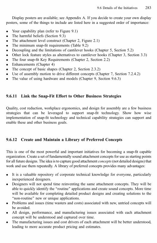
Display posters are available; see Appendix A. If you decide to create your own display
posters, some of the things to include are listed here in a suggested order of importance:
� Your capability plan (refer to Figure 9.1)
� The harmful beliefs (Section 9.3)
� The attachment level construct (Chapter 2, Figure 2.1)
� The minimum snap-fit requirements (Table 9.2)
� Decoupling and the limitations of cantilever hooks (Chapter 5, Section 5.2)
� Other lock feature styles as alternatives to cantilever hooks (Chapter 3, Section 3.3)
� The four snap-fit Key Requirements (Chapter 2, Section 2.2)
� Enhancements (Chapter 4)
� The concept of basic shapes (Chapter 2, Section 2.3.2)
� Use of assembly motion to drive different concepts (Chapter 7, Section 7.2.4.2)
� The value of using hardware and models (Chapter 9, Section 9.6.3)
9.6.11 Link the Snap-Fit Effort to Other Business Strategies
Quality, cost reduction, workplace ergonomics, and design for assembly are a few business
strategies that can be leveraged to support snap-fit technology. Show how wise
implementation of snap-fit technology and technical capability strategies can support and
enable these and other business goals.
9.6.12 Create and Maintain a Library of Preferred Concepts
This is one of the most powerful and important initiatives for becoming a snap-fit capable
organization. Create a set of fundamentally sound attachment concepts for use as starting points
for all future designs. The idea is to capture good attachment concepts (not detailed designs) that
work and use them repeatedly. A library of preferred concepts provides many advantages:
� It is a valuable repository of corporate technical knowledge for everyone, particularly
inexperienced designers.
� Designers will not spend time reinventing the same attachment concepts. They will be
able to quickly identify the ‘‘routine’’ applications and create sound concepts. More time
will be available for completing detailed product designs and creating solutions to the
‘‘non-routine’’ new or unique applications.
� Problems and issues (time wasters and costs) associated with new, untried concepts will
be avoided.
� All design, performance, and manufacturing issues associated with each attachment
concept will be understood and captured over time.
� The manufacturing issues and cost drivers of each attachment will be better understood,
leading to more accurate product pricing and estimates.
9.6 Details of the Initiatives 283

‘‘Preferred concepts’’ are arrangements of constraint features and enhancements that are
desirable and generic (or common) starting points for interface design.
A preferred concept is not a detailed design. It is a fundamentally sound (technically
correct and robust) arrangement of constraint features and certain enhancements. In its most
basic form, the preferred concept satisfies the minimum snap-fit requirements discussed in
Section 9.6.5. A preferred concept is adaptable to multiple applications having the same
basic shape combination.
When a new application (product) is proposed, an appropriate preferred interface
concept is identified. Then, using that concept as a starting point, the designers exercise their
creativity and expertise to
(1) select specific constraint feature styles,
(2) design those features, doing feature level calculations if necessary and determining
dimensions and tolerances, and
(3) add appropriate enhancements for the application.
A suggested approach to this initiative is to classify your existing snap-fit applications
according to their ‘‘Basic Shapes’’ (Chapter 2, Section 2.3.2). You may find that many
different applications actually fall into a limited number of shape combinations. For each
of those combinations, a limited number of ‘‘best’’ concepts that satisfy all the rules of
good snap-fits can be identified and then used on all similar applications. Table 2.4 in
Chapter 2 summarizes the available basic shape combinations. Table 2.5 shows the relative
frequency of these combinations in automotive applications. Of all the high-frequency
combinations observed by the author, the panel-opening basic shape combination was the
most common. This suggests high value in investigating and identifying a limited set of
preferred interface concepts for panel-opening applications. Figures 9.3, 9.4 and 9.5
illustrate this approach.
When an application cannot be readily classified by basic shape, a preferred attachment
concept that satisfies the rules of good snap-fits can still be defined and included in the
library for future generations of that product.
Establishing and maintaining a technical memory takes time and effort. Technical
memory will not happen or remain viable unless there is a long-term commitment to it.
Establishing the library, helping designers make contributions to it, and ensuring its use as a
technical resource should be the job of the snap-fit Technology Leader. The Champion should
show interest in the library and encourage, recognize, and reward contributions to the library.
Finally, make the library visible in a ‘‘preferred interfaces exhibit’’ with illustrations and
product examples of the most common applications. Make all of the library contents
available in an on-line resource if necessary. Establish a process to ensure that all new
knowledge gained is captured in the library.
9.6.13 Have a Model of the Snap-Fit Technical Domain
Use the Attachment Level model shown in Figure 2.1 in Chapter 2. Make the model visible
and continuously refer to it until it becomes second nature. Use the model as a tool to
284 Creating a Snap-Fit Capable Organization [Refs. on p. 291]

capture and organize knowledge gathered during benchmarking. Adopting the terminology
of the model and the feature and enhancement definitions is very important for creating a
common language for communicating about snap-fits.
You may wish to adapt the model as presented in this book to more closely represent
your particular product(s) and needs. If you do plan to adapt the model, it is recommended
that your designers and organization live with the book model for a couple of years until
sufficient expertise and understanding exist to make meaningful modifications. The model
as it exists has proven to be fairly robust.
:noitautisehT
esuftahtslaeversrerutcafunamynammorfsnoitacilppaevitomotuafoyevrusA
pmal,stuoesolc,srotaidar,sellirgrotaidar,slenapssecca,sellirgrekaeps,srood
-lenaPehtotnillafseceipmirtsuoenallecsimynamtaergadnasrotcelfer,sesnel
.noitanibmocepahscisabgninepO
tahtswohssnoitacilppaesehtfoydutsrehtrufA !tnereffidsienohcae ehtnitsujtoN
ehtnitub,snoisnemiderutaefecafretni ehT.tnemhcattaehtfotpecnoccisab
sitisastcudorps’rerutcafunamhcaenihtiwtaergsasisecnereffidfoegnar
9eraereht,sellirgrekaepstnereffid01rof,elpmaxeroF.srerutcafunamneewteb
llafo,snoitacilpparoodsseccaesufroF.sdohtemtnemhcattatnereffid
eraereht,rerutcafunamenonihtiW.snoitairav25eraereht,deidutssrerutcafunam
!snoitairav71
niylediwyravoslayehttahtslaeversnoitacilppaesehtfognikramhcneblacinhceT
rp,ytilibapacnoitneter,ylbmessafoesae deviecrep,ytilibaecivres,ytilibarudelbabo
eromroenoevahynam,doogrotnellecxeerawefA.ytilauqlautcadnaytilauq
.sngisedrooperaemosdnasgnimoctrohs
:noitseuqgibehT
tnemhcattaeuqinuatahtsnoitacilppaesehtfohcaetuobaeuqinuossitahW
?enohcaerofdedeensidohtem
:rewsnaehT
emasehtgnisudepolevedneebevahdluocsnoitacilppaehtfotsoM!GNIHTON
.tniopgnitratsasatpecnoCderreferP
Figure 9.3 A common product scenario
9.6 Details of the Initiatives 285
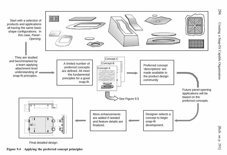
stnemecnahneeroMdedeenfideddaera
erasliatederutaefdna.dezilanif
tpecnocderreferPera’snoitpircsed‘otelbaliavaedamngisedtcudorpeht
ytinummoc
forebmundetimilAstpecnocderreferpteemllA.denifederalatnemadnufeht
doogarofselpicnirp.tif-pans
CtpecnoCBtpecnoC
AtpecnoC
deidutserayehTybdekramhcnebdnagniylppamaetaleveltnemhcattafognidnatsrednu.selpicnirptif-pans
astcelesrengiseDnigebottpecnoc
tif-pans.tnempoleved
.ngiseddeliatedlaniF
fonoitcelesahtiwtratSsnoitacilppadnastcudorpcisabemasehtgnivahllanI.snoitarugifnocepahs
,esacsiht -lenaPgninepO .
5.9erugiFeeS
gninepo-lenaperutuFeblliwsnoitacilppa
ehtnodesab.stpecnocderreferp
Figure 9.4 Applying the preferred concept principles
28
6C
reating
aS
nap
-Fit
Cap
able
Org
anizatio
n[R
efs.on
p.
29
1]

elytskcolkoohrevelitnaC.dettimreptonsi
hgiHA
ssem
bly
Mot
ion
Ass
embl
y M
otio
n
lamroNwoL
?ytixelpmoCecafretnIwoL
tpecnocderreferpgnitsixenA.elbacilppaebtonyam
woLhgiH?dnameD
lamroNwoL
elytskcolkoohrevelitnaC.dednemmocertonsi
erutaefkcoL?htgnelpirg
hsuP
piT
edilS
tsiwT
toviP
dexiF elbaevoM
*------
------
------
------
------
------
------
------
------
------
------
------
------
------
dexiF elbaevoM
hsuP
piT
edilS
tsiwT
toviP
dexiF elbaevoM dexiF
------
------
------
------
------
------
elbaevoM
noitcA noitcAnoitcA noitcA
AtpecnoC ------
DtpecnoC
BtpecnoC FtpecnoC
------
EtpecnoC
CtpecnoC ItpecnoC
------ ------
------
------
------
------
------
GtpecnoC
HtpecnoC ------
------
.yrassecensasllecytpmeehtnideddaebnacstpecnocderreferperoM*
ehtroF gninepO-lenaPnoitanibmoCepahScisaB
erutaefkcoL?htgnelpirg
Figure 9.5 Example of a basic shape combination organized into preferred concepts
9.6
Details
of
the
Initiativ
es2
87

9.6.14 Reward Teamwork and Make Snap-Fits Interesting
Benchmarking and the study of models are activities that lend themselves particularly well to
the synergy of team involvement. The learning and creativity that results will not only
improve the product, but will help make snap-fits fun. Recognize and reward clever solutions
to design problems and capture them in the library so they are available in the future.
� Have regular technical updates at departmental and staff meetings.
� Maintain a display of snap-fit successes and interesting or unique applications.
� Encourage writing and presenting technical papers and web-site articles.
� Have a snap-fit ‘‘war-room’’. Collect parts and display them.
� Encourage brainstorming sessions.
9.6.15 Identify Supportive Customers and Suppliers
Close cooperation between your company and companies upstream and downstream in the
product development=manufacturing process will help avoid some problems as your
organization develops snap-fit capability. A strategic partnership with certain customers or
suppliers for developing mutual capability may also be advantageous.
When your company must coordinate development of a part with another company’s part
because they are to be attached to one another, the interface becomes of common interest.
Some snap-fit decisions will drive cost into one or the other of the joined parts. One such
decision is deciding which part will carry the locking features. Having a common technical
basis for making decisions can help overcome non-technical cost issues that may become an
area of contention.
9.6.16 Initiatives Summary
Think of these fifteen initiatives as a wish list. Although all are important, the business realities
of limited time and resources may drive the need to exclude some of them. Some initiatives are
more critical to success than others; the author’s recommendations are shown in Table 9.3.
9.7 Summary
This chapter presented a plan for moving an engineering organization from a loose fastener
(primarily threaded-fastener) culture to one capable of making an informed choice between loose
fasteners and snap-fit attachment technology and then successfully executing snap-fit attachments
288 Creating a Snap-Fit Capable Organization [Refs. on p. 291]
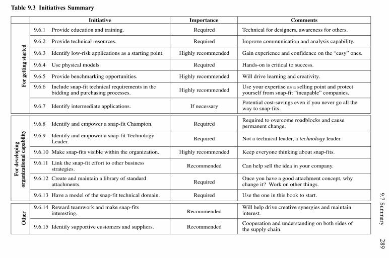
Initiative Importance Comments
9.6.1 Provide education and training. Required Technical for designers, awareness for others.
9.6.2 Provide technical resources. Required Improve communication and analysis capability.
9.6.3 Identify low-risk applications as a starting point. Highly recommended Gain experience and confidence on the “easy” ones.
9.6.4 Use physical models. Required Hands-on is critical to success.
9.6.5 Provide benchmarking opportunities. Highly recommended Will drive learning and creativity.
9.6.6 Include snap-fit technical requirements in the bidding and purchasing processes. Highly recommended
Use your expertise as a selling point and protectyourself from snap-fit “incapable” companies.
For
gett
ing
star
ted
9.6.7 Identify intermediate applications. If necessaryPotential cost-savings even if you never go all theway to snap-fits.
9.6.8 Identify and empower a snap-fit Champion. RequiredRequired to overcome roadblocks and causepermanent change.
9.6.9 Identify and empower a snap-fit Technology Leader. Required Not a technical leader, a technology leader.
9.6.10 Make snap-fits visible within the organization. Highly recommended Keep everyone thinking about snap-fits.
9.6.11 Link the snap-fit effort to other business strategies.
Recommended Can help sell the idea in your company.
9.6.12 Create and maintain a library of standard attachments. Required
Once you have a good attachment concept, whychange it? Work on other things.
For
deve
lopi
ngor
gani
zatio
nal c
apab
ility
9.6.13 Have a model of the snap-fit technical domain. Required Use the one in this book to start.
9.6.14 Reward teamwork and make snap-fits interesting. Recommended
Will help drive creative synergies and maintaininterest.
Oth
er
9.6.15 Identify supportive customers and suppliers. RecommendedCooperation and understanding on both sides ofthe supply chain.
Table 9.3 Initiatives Summary9
.7S
um
mary
28
9

when appropriate. Achieving snap-fit capability at both the individual level (a traditional
approach) and at the business or organizational level (a strategic approach) was discussed.
The goal is to make an informed choice between an existing attachment method and
snap-fit attachments and then successfully implement snap-fits when they are appropriate.
The key phrase is ‘‘informed choice’’. Both fastening methods have a place in product
design, the important issue from a cost, quality, and reliability standpoint is to choose the
right fastening method and then properly execute it.
The real time involved in becoming snap-fit capable is a function of many variables,
including business climate, the organization size, availability of resources, and available
talent. Individual expertise can be developed in a relatively short time compared to true
organizational capability. In a large engineering organization, allowing as much as 3 to 5
years for this kind of change to take hold is not unrealistic.
9.7.1 Important Points in Chapter 9
� Snap-fit expertise should be managed at both the individual and the organizational levels
to ensure good snap-fit designs and long-term technical excellence.
� There will be a learning curve for the new technology. Do not leap into snap-fit
technology on complex or critical attachments.
� Snap-fits are a true paradigm shift from threaded fastening methods, because snap-fits do
not rely on clamp load.
� Threaded fastener knowledge does not transfer to snap-fits. However, many principles of
good snap-fit design do transfer to threaded fastener attachments.
� Certain harmful beliefs can interfere with developing snap-fit capability. Be proactive
and repetitive in addressing them; many times, they will be unspoken.
� Piece cost will be higher with snap-fits; the savings are in ease of assembly and part
reduction.
� Include materials and processing experts in the snap-fit development process.
� Require that minimum snap-fit requirements be addressed on product proposals and bids.
� In many applications, a decision between a snap-fit or a threaded fastener does not have
to be made right away.
� The initiative ‘‘Create and maintain a library of preferred concepts’’ is so important that it
bears repeating here. The author feels strongly that this is one of the most powerful
things an organization can do to become snap-fit capable and to maintain that capability
over the long term.
9.7.2 Cautions
� Do not expect the Snap-Fit Technology Leader to do it all. Every designer should
become snap-fit capable, and some should become experts. Imagine a scenario where the
Technology Leader suddenly disappeared. What would happen to your snap-fit effort?
Ensure continuity in organizational snap-fit capability regardless of personnel changes.
290 Creating a Snap-Fit Capable Organization

� Do not expect overnight success. Study some well executed snap-fit attachments. You will
begin to appreciate the complexity of the problem. Remember that snap-fit development is
iterative, especially when the attachment is complex. Very few attachments will be perfect
the first time around. The goal is to minimize the number of design iterations.
� Play it safe and be conservative. You are still saving money over conventional fasteners.
With snap-fits, ‘‘over-design’’ often means simply designing thicker sections (more
strength) in the features, this is very inexpensive. Even adding more locking features for
more strength is very inexpensive if done during the concept stage.
� Allow additional time for snap-fit development. Recognize that the time and effort spent
in developing reliable and robust snap-fit (integral) attachments will likely exceed the
time spent on a threaded fastener type attachment for the same application. This is
especially true during the early learning phase. However, benefits that far exceed the
initial engineering costs will be realized when that design is assembled into thousands of
products without the cost of using assembly tools or loose fasteners.
Reference
1. Some of the ideas discussed in this chapter first appeared in ‘‘A Management Strategy for Implementing
Snap-Fit Technology’’, an article by the author published in Business Briefing: Global Automotive
Manufacturing and Technology, 2003.
Bibliography
Argyris, Chris, 1971, Management and Organizational Development, McGraw-Hill, New York.
Cummings, Thomas G. and Worley, Christopher G., 1997, Organization Development and Change, 6th ed.,
South-Western College Publishing, Cincinnati, OH.
Davenport, Thomas H. and Prusak, Laurence, 1998, Working Knowledge, Harvard Business School Press,
Boston, MA.
Drucker, Peter F., 1995, Managing in a Time of Great Change, Truman Talley Books=Dutton, New York.
Kotter, John P., 1996, Leading Change, Harvard Business School Press, Boston, MA.
Lindsay, William M. and Petrick, Joseph A., 1997, Total Quality and Organization Development, St. Lucie
Press, Boca Raton, FL.
Senge, Peter M.; Kleiner, Art; Roberts, Charlotte; Ross, Richard B. and Smith, Bryan J., 1994, The Fifth
Discipline Fieldbook, Doubleday, New York.
Tichy, Noel M., 1983, Managing Strategic Change, John Wiley and Sons, New York.
Walton, Mary, 1986, The Deming Management Method, The Berkeley Publishing Group, New York.
Zyngier, Suzanne; Burstein, Frada; McKay, Judy, Knowledge Management Governance: A Multifaceted
Approach to Organisational Decision and Innovation Support, the IFIP TC8=WG8.3 International
Conference, 2004.
9.7 Summary 291

Appendix A—Resources
In addition to the resources listed in Table 6.8 at the end of Chapter 6 and mentioned
throughout the book:
More snap-fit information can be found at:www.fasteningsmart.net
The site includes:
� More feature calculations
� Additional technical resources and references
� Availability of posters and displays about snap-fits
� Availability of training and instruction
� New discussion of snap-fit applications, this book and the technology
� Links to other useful sites
Author email: [email protected]
Finite element modeling of snap-fits and features:� A web-based finite-element analysis tool (FEMSnap) for a variety of lock feature shapes
is available at the Bayer MaterialScience website at:
http:==plastics.bayer.com=plastics=emea=en=femsnap=index.jsp
From the introduction to FEMSnap at this site: ‘‘FEMSnap is . . . a web-based calculation
service offered by Bayer MaterialScience to dimension miscellaneous snap-fits made of
various Bayer engineering thermoplastics.’’
� A finite element analysis tool for parts made of polymers is available from ANSYS, Inc. at:
http:==www.ansys.com=ANSYS Inc., Southpointe, 275 Technology Drive, Canonsburg, PA 15317.
Other reference sites:� The Bayer Design Guide (including feature calculations) is available online at:
https:==plastics.bayer.com.plastics=emea=en=docguard=A1119.pdf?docid¼ 1177
� The Honeywell Design Guide (with some feature calculations) is online at:
www.honeywell-plastics.com
� Plastics materials sites:
www.IDES.com
www.MATWEB.com

� Information about snap-fits and structural applications:
www.cerf.org=about=press=8_21_99.htm
www.new-technologies.org=ECT=Civil=snap.htm
www.strongwell-ebert.com
The sites listed here are, of course, not the only sources of analysis, design guides, and
materials information.
Appendix A 293

Index
Action (function), 27
Activation, 44, 109
Activation enhancements, 44, 109
Adjustable inserts, 125, 126
Adjustments to calculations, 186–197
Alignment requirements, 62, 127, 145
Alternative fasteners, 37, 246
Analysis, 69, 94, 162, 198, 199, 216, 243
Analysis example, 201–208
Annular (lock), 64, 68, 91
Application appropriate for snap-fit, 224–228
Assembly
–enhancements, 44, 96, 109
–force, 29, 106, 131, 162, 206
–force signature, 79, 85, 106
–motion, 38–40, 61, 62, 235, 237, 257
Assists (enhancement), 44, 109, 111, 113, 133
Assumptions for analysis, 164, 197
Attachment Level
–and design for assembly, 10
–and other attachments, 2, 11
–Construct, 1, 14, 223
–definition of, 6, 7, 47
–history, viii
–problem symptoms, 256
–vs. feature level, 6
Attachment type, 27
Back-up lock (enhancement), 44, 114, 119, 133
Base part, 31
Basic shapes, 272, 279, 282, 283
–and assembly motion, 40
–defined, 29, 31
–frequency in applications, 34
–tables, 34
Beam, 68, 155, 178, 199, 209
–terminology, 179
Beliefs, 268–270, 273, 290
Benchmarking, 95, 230, 271, 272, 277, 279, 284,
285, 289
–checklist, 231
–rules, 231
Bezel applications, 157–159
Bi-directional forces, 145
Cantilever hook, rules of thumb, 176
Cantilever lock, 68, 84
Capability, 266, 267, 271–278, 280, 282, 283, 288–290
Capable, 266, 267, 270, 272, 273, 275, 281,
283, 288–290
Catch (locator), 41, 50
Cavity (basic shape), 32, 34
Champion, 272, 277, 282, 284, 289
Checklists (worksheets)
–application appropriate for snap-fit, 225–227
–benchmarking, 231
–best concept, 244
–constraint worksheet examples, 143–149
–constraint worksheet original, 240
–feasibility, 253
–feature problem diagnosis, 260–263
–final evaluation, 251, 252
Clearance (enhancement), 46, 98, 131
Coefficient of friction, 173, 174
Coefficient of Linear Thermal Expansion, 176, 177
Company, 266, 268, 278, 281, 288, 289
Compatibility, 20, 22
Complexity, 268, 278, 290
Compliance (enhancement), 44, 67, 115–119, 133, 146
Concept, 267, 268, 272, 273, 275–278, 283, 284, 286,
289, 290
Concept development, 219
Cone (locator), 49
Constant section beam, 199–209
Constraint, 17, 40, 47, 57, 92, 135–150, 160, 337, 240
–features, 14, 47, 92
–improper, 19, 46, 139, 255
–pairs, 19, 145, 237
–proper, 20, 139
–rules, 141, 239
Cost, 101, 121
Couples, 63, 66
Creativity, 4, 218, 232
Creep, 175
Crush ribs (enhancement), 117, 118
Cutout (locator), 52
Darts (enhancement), 117, 118
Decoupling, 135, 151–160
–levels of, 153
–summary, 159
Deflection
–force, 204, 208
–magnification factor, 188–193
–magnification factor tables, 190, 191
–of mating feature=part, 186, 190–193, 204
Deflection-thickness ratio, 181
Degrees of Motion (DOM), 17, 58, 136, 139
–and locator pairs, 57
–maximize removal of, 60, 62, 142
Demand, 268, 269, 278, 280, 282

Descriptive elements, 25
Design, 266–270, 272, 273, 275–278, 280–285,
290, 291
Design for assembly
–process, 10
–practitioners, 10
Design point, 168–171
Design rules, 46, 55, 93, 120, 131, 141, 145, 160, 176,
231–241, 246
Designer, 266, 267, 269–273, 275–277, 279, 283, 284,
289, 290
Development, 266–268, 270, 272, 273, 275–279, 281,
282, 288, 290
Diagnosis, 135, 254,
–at the attachment level, 257
–at the feature level, 259
–tables, 260–263
Difficult assembly, causes of, 258
Dimensional
–control, 62
–robustness, 116
Distorted parts, causes of, 258
Draft angle, 123
DTUL, 175
Edge (locator), 51
Effective angle, 186, 193, 206
Efficiency, lock 89
Elastic limit, 166
Elasticity (enhancement), 119
Elements, 13, 14, 25, 26, 43, 44, 45
–and the development process, 224
Enclosure (basic shape), 32, 34
Engage direction, 35, 145, 233, 236
Engineering, 272, 273, 275–277, 288, 290, 291
Enhancements, 7, 11, 14, 43, 95–134, 232, 242, 279,
281, 283, 284
–and the development process, 132
–for activation, 43, 109
–for assembly, 43, 96, 108
–for manufacturing, 43, 120
–for performance, 43, 114
–required, 128, 131, 280
–summary table, 45, 129
Ergonomics, 37, 131, 237
Evaluation
–initial strain, 185
–final, 251–252
Examples, 30, 100–104, 108, 150
Fasteners, 227, 228, 245–249
Feature
–analysis, 163
–damage, causes of, 109, 115, 258
Feasibility, 278, 281, 253
Feature level, 11, 12
–diagnosis, 258–263
–vs. attachment level, 6
Feedback (enhancement), 104, 131, 256
Final (attachment type), 28
Fine-tuning, 44, 64, 121, 125, 127, 133, 147, 250
Finite element analysis, 198
Fixed snap-fits (action), 27
Forces, 36, 81, 235
Function, 27–30, 91, 229
–summary, 30
Gates, 73, 124
Grip length, 280
Guards (enhancement), 44, 112, 114
Guidance (enhancement), 43, 96, 109
Guides (enhancement), 97, 103, 131,
Hands on, 8, 237
Harmful beliefs, 268–270, 290
High assembly force, 80, 109, 258
High assembly force, fixes for, 260
High-complexity, 268
High-demand, 268
High separation force, fixes for, 263
High strain or damage in features,
fixes for, 261
Hole (locator), 52
Hook (lock), 176, 199, 209, 211
Hook styles, 68, 75, 76
IBM, 8
Impact force or load, 28, 36, 168, 197
Improper constraint, 19, 46, 135, 139, 255
Initiative(s), 271, 272, 275–289
Insertion face, 78, 80
–angle, 87, 153, 180, 193, 206
–profile, 78, 80, 105, 113, 213
Insertion force signature, 79, 80, 85, 106, 214
Inserts, adjustable, 125
Integral attachment, vii, 4
Isolators (enhancement), 119
Key requirements, 14, 16, 25, 45
Knitlines, 73
Land (locator), 41, 50, 64
Length of beam, 179
Length to thickness ratio, 180, 189
Level 0, (decoupling), 153
Level 1, (decoupling), 154
Level 2, (decoupling), 155
Level 3, (decoupling), 156
Index 295

Level 4, (decoupling), 156
Line-of-action, 58, 59, 65
Living hinge (locator), 54
Local yield (enhancement), 117
Locators, 40, 41, 47, 48, 55, 67, 74, 92, 93
–design rules, 55
–pairs, 57, 61, 63
–styles, 48
–summary, 56
Lock type (function), 29
Locks, 42, 43, 44, 67, 68, 74, 84, 85, 119, 139
–alternatives, 246
–damage, fixes for, 262
–decoupling, 151, 159, 160
–efficiency, 89, 90, 92, 159
–pairs, 42, 77, 91
–styles, 67, 68, 75, 76
Loops (lock), 70, 72, 74, 93, 157
Loose
–fasteners, 120, 245
–parts, causes of, 259
Low-complexity, 268
Low-demand, 268, 269, 278, 280, 282
Low retention strength, fixes for, 262
Lug
–as a locator, 41, 48
–as a lock, 74, 77, 78
Manager, 266, 267, 270, 271
Manual or non-releasing locks (lock type), 30, 72,
88, 115
Manufacturing enhancements, 44, 120, 121
Material properties, 163
–other effects, 173
–sources for, 164
Mating feature deflection, 186, 190–193, 204
Mating part, 31
–deflection, 186, 190–193, 204
Maximize DOM removed, 58, 60, 142
Maximum
–allowable strain, 172, 201, 216
–assembly force, 205, 208
Mechanical advantage, 64
Metal clips, 245, 249
Metal-safe (enhancement), 125
Metal-to-metal snap-fits, 5
Metal-to-plastic snap-fits, 5
Minimum Requirements, 279, 280
Mission, 273
Models, use of, 237, 266, 272, 273, 277–279,
283, 285
Mold adjustment, 44, 125
Moveable (action), 27
Multiple concepts, 232
Natural locator, 40, 41, 48
Nesting, 40, 161
Noise
–background, 105, 107
–squeak and rattle, 116
Non-permanent (retention), 29
Non-releasing or manual locks (lock type), 30, 72, 88, 115
Objective(s), 273, 275–277
Opening (basic shape), 32, 34
Opposing features, 140
Organization(s), 266–268, 270–273, 275–278, 283,
285, 288–290
Other attachments, 2, 11
Over-constraint, 20, 142, 160, 161, 241, 256, 257
–opposing features, 140
–redundant features, 140
Panel (basic shape), 31, 34
Perfect constraint, 136, 139, 148, 150, 160
Performance enhancements, 44, 114
Permanent locks (retention), 28
Physical elements, 25
Pilot (enhancement), 99
Pin (locator), 50
Pivot (assembly motion), 38, 142
Planar (lock), 68, 84
Plastic push-in fasteners, 245, 248
Polaroid, 8, 134
Preferred concept(s), 277, 283, 284–287
Process-friendly (enhancement), 44, 121, 133, 256
Proper constraint, 20, 25, 46, 139, 160, 163
Proportional limit, 166
Prototypes, 238
Protrusion spacing, 123
Purchasing, 271, 276, 277, 279, 281, 289
Push (assembly motion), 38, 60, 142, 236
Push-in fasteners, 245, 248
Q-factor, 189
Radius, 98, 122, 124
Redundant features, 140
Release behavior, 71, 207
Releasing lock (lock type), 73
Required enhancements, 128, 131, 280
Retainers (enhancement), 84, 115, 159
Retention, 28, 67, 68, 70, 80, 82, 84, 87, 90, 156, 157,
162, 180–182, 195, 206
Retention (function), 28
Retention
–mechanism, 70
–signature, 83, 85
–strength, 71, 72, 80, 115, 157, 162, 206
296 Index

Retention face, 80, 181, 215
–angle, 80, 181, 195
–depth, 180
–profile, 80, 83, 213
Robustness, 21, 23, 25, 43, 116
Rules of thumb, cantilever hook, 176
Sample parts, 8
Screws, 245, 248
Secant modulus, 167, 171
Section properties, 199
Section changes, 123, 124
Separation, 71, 81, 145, 180, 206
–direction, 35
–force, 60, 81, 145, 206
Separation force, fixes for high, 263
Shut-off angle, 123, 124
Side-action hook, 109, 155, 160
Sinkmarks, 124
Slide (assembly motion), 38, 142
Slot (locator), 52
Snap-fit, 3, 4
–attachment level definition of, 6, 7, 47
–feature level definition of, 2
–structural, 5
–vs. threaded fastener, 5, 224, 228
Solid (basic shape), 31, 34
Sources of materials data, 163
Spatial
–elements, 25
–reasoning, 4
Spring clips, 250
Standard attachment(s), 272, 289
Strain, 169, 172, 173, 199, 201–203, 208, 260
Strain limit, 185
Strategies, 275–277, 283, 284
Strategy, 267, 275, 276, 291
Strength, 16, 17, 57, 128, 133, 168, 261
Stress concentration, 186, 202
Stress-strain curve, 164, 165, 176
Structural snap-fits, 5
Surface
–as a basic shape, 32
–as a locator, 34, 50
Symbols, as visual enhancements, 111
Tab (locator), 48
Tapered
–beams, 209
–features, as compliance enhancements, 117
Technology leader, 272, 276, 277, 282, 284, 285,
289, 290
Temporary lock (attachment type), 28
Terminology, 55, 178, 200
Thermal effects, 141, 142, 176, 177
Thick sections, 123, 124, 176
Thickness tapered beam, 209
Thickness and width tapered beam, 212
Threaded fasteners, 245–248
–vs. snap-fit, 5, 228
Threshold angle, 182
Tip (assembly motion), 38, 60, 98, 142, 236
Tolerance, 21, 44, 63, 114, 116, 125, 128, 133, 136,
139, 163, 176
Torsional lock, 64, 68, 90
Track (locator), 48, 49
Trap (lock), 64, 68, 85–87, 89, 157
Twist (assembly motion), 38, 142
Ultimate strength, 166
Under-constraint, 20, 139, 241, 256, 257, 258
Unintended release (or separation), 29, 36, 81, 182, 207
User-feel (enhancement), 113
Values, 273
Vision, 273, 277
Visuals (enhancement), 44, 109, 110
Wall
–deflection, 188–190
–thickness, 122
Wedge (locator), 49
Width of beam, 184
Worksheets (checklists)
–application appropriate for snap-fit, 225–227
–benchmarking, 231
–best concept, 244
–constraint worksheet examples, 143–149
–constraint worksheet original, 240
–feasibility, 253
–feature problem diagnosis, 260–263
–final evaluation, 251, 252
Width tapered beam, 211
Yield
–point, 166
–strength, 167
Index 297

Contents
1 Snap-Fits and the Attachment LevelTM Construct . . . . . . . . . . . . . . . . 1
1.1 Introduction . . . . . . . . . . . . . . . . . . . . . . . . . . . . . . . . . . . . . . . . . . . . 1
1.2 Reader Expectations . . . . . . . . . . . . . . . . . . . . . . . . . . . . . . . . . . . . . . 2
1.3 Snap-Fit Technology . . . . . . . . . . . . . . . . . . . . . . . . . . . . . . . . . . . . . . 4
1.4 Feature Level and Attachment Level . . . . . . . . . . . . . . . . . . . . . . . . . . . 6
1.5 Using this Book . . . . . . . . . . . . . . . . . . . . . . . . . . . . . . . . . . . . . . . . . 8
1.5.1 The Importance of Sample Parts . . . . . . . . . . . . . . . . . . . . . . . . . . 8
1.5.2 Snap-Fit Novices . . . . . . . . . . . . . . . . . . . . . . . . . . . . . . . . . . . . 8
1.5.3 Experienced Designers . . . . . . . . . . . . . . . . . . . . . . . . . . . . . . . . 10
1.5.4 Design for Assembly Practitioners . . . . . . . . . . . . . . . . . . . . . . . . . 10
1.5.5 Engineering Managers and Executives . . . . . . . . . . . . . . . . . . . . . . 10
1.6 Chapter Synopses . . . . . . . . . . . . . . . . . . . . . . . . . . . . . . . . . . . . . . . . 10
1.7 Extending the ALC to Other Attachments . . . . . . . . . . . . . . . . . . . . . . . . 11
1.8 Summary. . . . . . . . . . . . . . . . . . . . . . . . . . . . . . . . . . . . . . . . . . . . . . 11
1.8.1 Important Points in Chapter 1. . . . . . . . . . . . . . . . . . . . . . . . . . . . 12
2 Overview of the Attachment LevelTM Construct . . . . . . . . . . . . . . . . . 14
2.1 Introduction . . . . . . . . . . . . . . . . . . . . . . . . . . . . . . . . . . . . . . . . . . . . 14
2.2 The Key Requirements. . . . . . . . . . . . . . . . . . . . . . . . . . . . . . . . . . . . . 14
2.2.1 Strength . . . . . . . . . . . . . . . . . . . . . . . . . . . . . . . . . . . . . . . . . . 16
2.2.2 Constraint . . . . . . . . . . . . . . . . . . . . . . . . . . . . . . . . . . . . . . . . . 17
2.2.2.1 Improper Constraint . . . . . . . . . . . . . . . . . . . . . . . . . . . . . 19
2.2.3 Compatibility . . . . . . . . . . . . . . . . . . . . . . . . . . . . . . . . . . . . . . . 20
2.2.4 Robustness . . . . . . . . . . . . . . . . . . . . . . . . . . . . . . . . . . . . . . . . 21
2.3 Elements of a Snap-Fit. . . . . . . . . . . . . . . . . . . . . . . . . . . . . . . . . . . . . 25
2.3.1 Function . . . . . . . . . . . . . . . . . . . . . . . . . . . . . . . . . . . . . . . . . . 27
2.3.1.1 Action . . . . . . . . . . . . . . . . . . . . . . . . . . . . . . . . . . . . . . 27
2.3.1.2 Attachment type . . . . . . . . . . . . . . . . . . . . . . . . . . . . . . . 27
2.3.1.3 Retention . . . . . . . . . . . . . . . . . . . . . . . . . . . . . . . . . . . . 28
2.3.1.4 Lock type . . . . . . . . . . . . . . . . . . . . . . . . . . . . . . . . . . . 29
2.3.1.5 Function Summary . . . . . . . . . . . . . . . . . . . . . . . . . . . . . 29
2.3.2 Basic Shapes . . . . . . . . . . . . . . . . . . . . . . . . . . . . . . . . . . . . . . . 29
2.3.2.1 Mating Part and Base Part . . . . . . . . . . . . . . . . . . . . . . . . 31
2.3.2.2 Basic Shape Descriptions . . . . . . . . . . . . . . . . . . . . . . . . . 31
2.3.2.3 Basic Shape Summary . . . . . . . . . . . . . . . . . . . . . . . . . . . 33

2.3.3 Engage Direction . . . . . . . . . . . . . . . . . . . . . . . . . . . . . . . . . . . . 35
2.3.4 Assembly Motion. . . . . . . . . . . . . . . . . . . . . . . . . . . . . . . . . . . . 38
2.3.5 Constraint Features. . . . . . . . . . . . . . . . . . . . . . . . . . . . . . . . . . . 40
2.3.5.1 Locator Features . . . . . . . . . . . . . . . . . . . . . . . . . . . . . . . 40
2.3.5.2 Lock Features. . . . . . . . . . . . . . . . . . . . . . . . . . . . . . . . . 41
2.3.6 Enhancements . . . . . . . . . . . . . . . . . . . . . . . . . . . . . . . . . . . . . . 43
2.3.7 Elements Summary . . . . . . . . . . . . . . . . . . . . . . . . . . . . . . . . . . 44
2.4 Summary . . . . . . . . . . . . . . . . . . . . . . . . . . . . . . . . . . . . . . . . . . . . . 45
2.4.1 Important Points in Chapter 2 . . . . . . . . . . . . . . . . . . . . . . . . . . . 46
2.4.2 Important Design Rules Introduced in Chapter 2 . . . . . . . . . . . . . . . 46
3 Constraint Features . . . . . . . . . . . . . . . . . . . . . . . . . . . . . . . . . . . . . . . 47
3.1 Introduction. . . . . . . . . . . . . . . . . . . . . . . . . . . . . . . . . . . . . . . . . . . . 47
3.2 Locator Features. . . . . . . . . . . . . . . . . . . . . . . . . . . . . . . . . . . . . . . . . 47
3.2.1 Locator Styles . . . . . . . . . . . . . . . . . . . . . . . . . . . . . . . . . . . . . . 48
3.2.1.1 Lug . . . . . . . . . . . . . . . . . . . . . . . . . . . . . . . . . . . . . . 48
3.2.1.2 Tab . . . . . . . . . . . . . . . . . . . . . . . . . . . . . . . . . . . . . . . 48
3.2.1.3 Wedge. . . . . . . . . . . . . . . . . . . . . . . . . . . . . . . . . . . . . 49
3.2.1.4 Cone. . . . . . . . . . . . . . . . . . . . . . . . . . . . . . . . . . . . . . 49
3.2.1.5 Pin . . . . . . . . . . . . . . . . . . . . . . . . . . . . . . . . . . . . . . . 50
3.2.1.6 Catch . . . . . . . . . . . . . . . . . . . . . . . . . . . . . . . . . . . . . 50
3.2.1.7 Surface . . . . . . . . . . . . . . . . . . . . . . . . . . . . . . . . . . . . 50
3.2.1.8 Land . . . . . . . . . . . . . . . . . . . . . . . . . . . . . . . . . . . . . . 50
3.2.1.9 Edge . . . . . . . . . . . . . . . . . . . . . . . . . . . . . . . . . . . . . . 51
3.2.1.10 Hole . . . . . . . . . . . . . . . . . . . . . . . . . . . . . . . . . . . . . . 52
3.2.1.11 Slot . . . . . . . . . . . . . . . . . . . . . . . . . . . . . . . . . . . . . . 52
3.2.1.12 Cutout. . . . . . . . . . . . . . . . . . . . . . . . . . . . . . . . . . . . . 52
3.2.1.13 Living Hinge . . . . . . . . . . . . . . . . . . . . . . . . . . . . . . . . 54
3.2.2 Design Practices for Locator Pairs . . . . . . . . . . . . . . . . . . . . . . . . 55
3.2.2.1 Terminology. . . . . . . . . . . . . . . . . . . . . . . . . . . . . . . . . . 55
3.2.2.2 Locator Pairs, Constraint and Strength . . . . . . . . . . . . . . . . 57
3.2.2.3 Locator Pairs and Ease of Assembly . . . . . . . . . . . . . . . . . 62
3.2.2.4 Locator Pairs and Dimensional Control . . . . . . . . . . . . . . . 62
3.2.2.5 Locator Pairs and Mechanical Advantage . . . . . . . . . . . . . . 65
3.2.2.6 Locator Pairs and Compliance. . . . . . . . . . . . . . . . . . . . . . 67
3.2.2.7 Locators Summary . . . . . . . . . . . . . . . . . . . . . . . . . . . . . 67
3.3 Lock Features . . . . . . . . . . . . . . . . . . . . . . . . . . . . . . . . . . . . . . . . . . 67
3.3.1 Lock Feature Styles . . . . . . . . . . . . . . . . . . . . . . . . . . . . . . . . . . 68
3.3.2 Cantilever Beam Locks . . . . . . . . . . . . . . . . . . . . . . . . . . . . . . . . 68
3.3.2.1 The Deflection Mechanism. . . . . . . . . . . . . . . . . . . . . . . . 69
3.3.2.2 The Retention Mechanism . . . . . . . . . . . . . . . . . . . . . . . . 70
3.3.2.3 Cantilever Lock Examples . . . . . . . . . . . . . . . . . . . . . . . . 74
3.3.2.4 Locators as Cantilever Locks . . . . . . . . . . . . . . . . . . . . . . 74
3.3.2.5 Lock Pairs . . . . . . . . . . . . . . . . . . . . . . . . . . . . . . . . . . . 77
xiv Contents
3.3.2.6 Cantilever Lock Assembly Behavior . . . . . . . . . . . . . . . . . . 78
3.3.2.7 Cantilever Lock Retention and
Disassembly Behavior . . . . . . . . . . . . . . . . . . . . . . . . . . 80
3.3.3 Planar Locks . . . . . . . . . . . . . . . . . . . . . . . . . . . . . . . . . . . . . . 84
3.3.4 Trap Locks . . . . . . . . . . . . . . . . . . . . . . . . . . . . . . . . . . . . . . . 85
3.3.4.1 Trap Assembly Behavior. . . . . . . . . . . . . . . . . . . . . . . . . 87
3.3.4.2 Trap Retention and Disassembly . . . . . . . . . . . . . . . . . . . 87
3.3.4.3 Traps and Lock Efficiency . . . . . . . . . . . . . . . . . . . . . . . 89
3.3.5 Torsional Lock. . . . . . . . . . . . . . . . . . . . . . . . . . . . . . . . . . . . . 90
3.3.6 Annular Lock . . . . . . . . . . . . . . . . . . . . . . . . . . . . . . . . . . . . . 91
3.3.7 Lock Pairs and Lock Function . . . . . . . . . . . . . . . . . . . . . . . . . . 91
3.4 Selecting a Locking Feature . . . . . . . . . . . . . . . . . . . . . . . . . . . . . . . . 92
3.5 Summary. . . . . . . . . . . . . . . . . . . . . . . . . . . . . . . . . . . . . . . . . . . . . 92
3.5.1 Important Points in Chapter 3. . . . . . . . . . . . . . . . . . . . . . . . . . . 93
3.5.2 Design Rules Introduced in Chapter 3 . . . . . . . . . . . . . . . . . . . . . 93
4 Enhancements . . . . . . . . . . . . . . . . . . . . . . . . . . . . . . . . . . . . . . . . . . . 95
4.1 Introduction . . . . . . . . . . . . . . . . . . . . . . . . . . . . . . . . . . . . . . . . . . . 95
4.2 Enhancements for Assembly . . . . . . . . . . . . . . . . . . . . . . . . . . . . . . . . 96
4.2.1 Guidance Enhancements . . . . . . . . . . . . . . . . . . . . . . . . . . . . . . 96
4.2.1.1 Guides. . . . . . . . . . . . . . . . . . . . . . . . . . . . . . . . . . . . . 97
4.2.1.2 Clearance. . . . . . . . . . . . . . . . . . . . . . . . . . . . . . . . . . . 98
4.2.1.3 Pilots. . . . . . . . . . . . . . . . . . . . . . . . . . . . . . . . . . . . . . 99
4.2.2 Product Example 1 . . . . . . . . . . . . . . . . . . . . . . . . . . . . . . . . . . 101
4.2.3 Product Example 2 . . . . . . . . . . . . . . . . . . . . . . . . . . . . . . . . . . 102
4.2.4 Product Example 3 . . . . . . . . . . . . . . . . . . . . . . . . . . . . . . . . . . 102
4.2.5 Operator Feedback . . . . . . . . . . . . . . . . . . . . . . . . . . . . . . . . . . 104
4.2.6 Product Example #3 Revisited . . . . . . . . . . . . . . . . . . . . . . . . . . 108
4.2.7 Assembly Enhancements Summary . . . . . . . . . . . . . . . . . . . . . . . 109
4.3 Enhancements for Activating and Using Snap-Fits . . . . . . . . . . . . . . . . . 109
4.3.1 Visuals . . . . . . . . . . . . . . . . . . . . . . . . . . . . . . . . . . . . . . . . . . 109
4.3.2 Assists . . . . . . . . . . . . . . . . . . . . . . . . . . . . . . . . . . . . . . . . . . 111
4.3.3 User Feel . . . . . . . . . . . . . . . . . . . . . . . . . . . . . . . . . . . . . . . . 113
4.4 Enhancements for Snap-Fit Performance . . . . . . . . . . . . . . . . . . . . . . . . 114
4.4.1 Guards . . . . . . . . . . . . . . . . . . . . . . . . . . . . . . . . . . . . . . . . . . 114
4.4.2 Retainers. . . . . . . . . . . . . . . . . . . . . . . . . . . . . . . . . . . . . . . . . 115
4.4.3 Compliance . . . . . . . . . . . . . . . . . . . . . . . . . . . . . . . . . . . . . . . 115
4.4.3.1 Compliance through Local Yield . . . . . . . . . . . . . . . . . . . 117
4.4.3.2 Compliance through Elasticity . . . . . . . . . . . . . . . . . . . . . 119
4.4.3.3 Isolators. . . . . . . . . . . . . . . . . . . . . . . . . . . . . . . . . . . . 119
4.4.4 Back-Up Locks . . . . . . . . . . . . . . . . . . . . . . . . . . . . . . . . . . . . 119
4.5 Enhancements for Snap-Fit Manufacturing . . . . . . . . . . . . . . . . . . . . . . 120
4.5.1 Process-Friendly . . . . . . . . . . . . . . . . . . . . . . . . . . . . . . . . . . . . 121
4.5.2 Fine-Tuning . . . . . . . . . . . . . . . . . . . . . . . . . . . . . . . . . . . . . . . 125
Contents xv

4.6 Summary . . . . . . . . . . . . . . . . . . . . . . . . . . . . . . . . . . . . . . . . . . . 128
4.6.1 Important Points in Chapter 4 . . . . . . . . . . . . . . . . . . . . . . . . . 128
4.6.2 Design Rules Introduced in Chapter 4 . . . . . . . . . . . . . . . . . . . 131
5 Fundamental Snap-Fit Concepts . . . . . . . . . . . . . . . . . . . . . . . . . . . . 135
5.1 The Importance of Constraint . . . . . . . . . . . . . . . . . . . . . . . . . . . . . 135
5.1.1 Constraint Review . . . . . . . . . . . . . . . . . . . . . . . . . . . . . . . . 136
5.1.2 Constraint Principles . . . . . . . . . . . . . . . . . . . . . . . . . . . . . . . 136
5.1.2.1 Perfect Constraint . . . . . . . . . . . . . . . . . . . . . . . . . . . 136
5.1.2.2 Proper Constraint . . . . . . . . . . . . . . . . . . . . . . . . . . . 139
5.1.2.3 Proper Constraint in Less than 12 DOM . . . . . . . . . . . . 139
5.1.2.4 Under-Constraint . . . . . . . . . . . . . . . . . . . . . . . . . . . . 139
5.1.2.5 Over-Constraint. . . . . . . . . . . . . . . . . . . . . . . . . . . . . 140
5.1.2.6 General Constraint Rules . . . . . . . . . . . . . . . . . . . . . . 141
5.1.3 The Constraint Worksheet . . . . . . . . . . . . . . . . . . . . . . . . . . . 143
5.1.4 Additional Comments on Constraint . . . . . . . . . . . . . . . . . . . . 151
5.2 Lock Decoupling . . . . . . . . . . . . . . . . . . . . . . . . . . . . . . . . . . . . . 151
5.2.1 The Lock Feature Paradox . . . . . . . . . . . . . . . . . . . . . . . . . . . 151
5.2.2 Decoupling Examples . . . . . . . . . . . . . . . . . . . . . . . . . . . . . . 151
5.2.3 Levels of Decoupling . . . . . . . . . . . . . . . . . . . . . . . . . . . . . . 153
5.2.3.1 No Decoupling (Level 0) . . . . . . . . . . . . . . . . . . . . . . 153
5.2.3.2 Level 1 Decoupling . . . . . . . . . . . . . . . . . . . . . . . . . . 154
5.2.3.3 Level 2 Decoupling . . . . . . . . . . . . . . . . . . . . . . . . . . 155
5.2.3.4 Level 3 Decoupling . . . . . . . . . . . . . . . . . . . . . . . . . . 156
5.2.3.5 Level 4 Decoupling . . . . . . . . . . . . . . . . . . . . . . . . . . 156
5.2.4 Decoupling Summary . . . . . . . . . . . . . . . . . . . . . . . . . . . . . . 159
5.3 Summary . . . . . . . . . . . . . . . . . . . . . . . . . . . . . . . . . . . . . . . . . . . 160
5.3.1 Important Points in Chapter 5 . . . . . . . . . . . . . . . . . . . . . . . . . 160
5.3.2 Design Rules Introduced in Chapter 5 . . . . . . . . . . . . . . . . . . . 160
6 Feature Design and Analysis . . . . . . . . . . . . . . . . . . . . . . . . . . . . . . . 162
6.1 Pre-Conditions for Feature Analysis . . . . . . . . . . . . . . . . . . . . . . . . . . 163
6.2 Material Property Data Needed for Analysis . . . . . . . . . . . . . . . . . . . . 163
6.2.1 Sources of Materials Data . . . . . . . . . . . . . . . . . . . . . . . . . . . . 163
6.2.2 Assumptions for Analysis . . . . . . . . . . . . . . . . . . . . . . . . . . . . 164
6.2.3 The Stress-Strain Curve. . . . . . . . . . . . . . . . . . . . . . . . . . . . . . 165
6.2.4 Establishing a Design Point . . . . . . . . . . . . . . . . . . . . . . . . . . . 168
6.2.4.1 For Applications Where Strain is Fixed. . . . . . . . . . . . . . 169
6.2.4.2 For Applications Where Strain is Variable . . . . . . . . . . . . 170
6.2.4.3 Materials With a Definite Yield Point . . . . . . . . . . . . . . . 170
6.2.4.4 Materials Without a Definite Yield Point . . . . . . . . . . . . . 170
6.2.4.5 The Secant Modulus . . . . . . . . . . . . . . . . . . . . . . . . . . 171
6.2.4.6 Maximum Permissible Strain Data . . . . . . . . . . . . . . . . . 171
xvi Contents

6.2.5 Coefficient of Friction (m). . . . . . . . . . . . . . . . . . . . . . . . . . . . 173
6.2.6 Other Effects . . . . . . . . . . . . . . . . . . . . . . . . . . . . . . . . . . . . 173
6.3 Cantilever Hook Design Rules of Thumb . . . . . . . . . . . . . . . . . . . . . 176
6.3.1 Beam Thickness at the Base . . . . . . . . . . . . . . . . . . . . . . . . . . 178
6.3.2 Beam Length . . . . . . . . . . . . . . . . . . . . . . . . . . . . . . . . . . . . 179
6.3.3 Insertion Face Angle . . . . . . . . . . . . . . . . . . . . . . . . . . . . . . . 180
6.3.4 Retention Face Depth. . . . . . . . . . . . . . . . . . . . . . . . . . . . . . . 180
6.3.5 Retention Face Angle. . . . . . . . . . . . . . . . . . . . . . . . . . . . . . . 181
6.3.6 The Threshold Angle . . . . . . . . . . . . . . . . . . . . . . . . . . . . . . . 182
6.3.7 Beam Thickness at the Retention Feature . . . . . . . . . . . . . . . . . 182
6.3.8 Beam Width . . . . . . . . . . . . . . . . . . . . . . . . . . . . . . . . . . . . . 184
6.3.9 Other Features . . . . . . . . . . . . . . . . . . . . . . . . . . . . . . . . . . . 185
6.4 Initial Strain Evaluation . . . . . . . . . . . . . . . . . . . . . . . . . . . . . . . . . 185
6.5 Adjustments to Calculations . . . . . . . . . . . . . . . . . . . . . . . . . . . . . . 186
6.5.1 Adjustment for Stress Concentration. . . . . . . . . . . . . . . . . . . . . 186
6.5.2 Adjustment for Wall Deflection . . . . . . . . . . . . . . . . . . . . . . . . 188
6.5.3 Adjustment for Mating Feature Deflection . . . . . . . . . . . . . . . . . 190
6.5.4 Adjustments for Effective Angle . . . . . . . . . . . . . . . . . . . . . . . 193
6.5.4.1 Effective Angle for the Insertion Face . . . . . . . . . . . . . . 193
6.5.4.2 Effective Angle for the Retention Face . . . . . . . . . . . . . 195
6.5.5 Adjustments Summary . . . . . . . . . . . . . . . . . . . . . . . . . . . . . . 197
6.6 Assumptions for Analysis . . . . . . . . . . . . . . . . . . . . . . . . . . . . . . . . 197
6.7 Using Finite Element Analysis . . . . . . . . . . . . . . . . . . . . . . . . . . . . . 198
6.8 Determine the Conditions for Analysis . . . . . . . . . . . . . . . . . . . . . . . 198
6.9 Cantilever Hook Analysis for a Constant Rectangular Section Beam . . . 199
6.9.1 Section Properties and the Relation between Stress and Strain . . . 199
6.9.2 Evaluating Maximum Strain . . . . . . . . . . . . . . . . . . . . . . . . . . 201
6.9.2.1 Adjusting Maximum Allowable Strain for
Stress Concentrations . . . . . . . . . . . . . . . . . . . . . . . . . 202
6.9.2.2 Calculating the Maximum Applied Strain in a Constant
Section Beam . . . . . . . . . . . . . . . . . . . . . . . . . . . . . . 202
6.9.2.3 Adjusting the Calculated Strain for Deflection
Magnification . . . . . . . . . . . . . . . . . . . . . . . . . . . . . . 202
6.9.3 Calculating Deflection Force . . . . . . . . . . . . . . . . . . . . . . . . . . 203
6.9.4 Adjusting for Mating Part=Feature Deflection. . . . . . . . . . . . . . . 204
6.9.5 Determine Maximum Assembly Force . . . . . . . . . . . . . . . . . . . 205
6.9.5.1 Determine the Effective Insertion Face Angle . . . . . . . . . 205
6.9.6 Determine Release Behavior . . . . . . . . . . . . . . . . . . . . . . . . . . 206
6.9.6.1 Calculate the Effective Retention Face Angles . . . . . . . . 206
6.9.6.2 Calculate the Separation Forces . . . . . . . . . . . . . . . . . . 207
6.9.6.3 Other Retention Considerations . . . . . . . . . . . . . . . . . . 208
6.10 Cantilever Hook Tapered in Thickness . . . . . . . . . . . . . . . . . . . . . . . 209
6.11 Cantilever Hook Tapered in Width . . . . . . . . . . . . . . . . . . . . . . . . . . 211
6.12 Cantilever Hook Tapered in Thickness and Width . . . . . . . . . . . . . . . . 212
6.13 Modifications to the Insertion Face Profile . . . . . . . . . . . . . . . . . . . . . 212
Contents xvii

6.14 Modifications to the Retention Face Profile . . . . . . . . . . . . . . . . . . . . 215
6.15 Other Feature Calculations . . . . . . . . . . . . . . . . . . . . . . . . . . . . . . . 215
6.16 Summary . . . . . . . . . . . . . . . . . . . . . . . . . . . . . . . . . . . . . . . . . . . 216
6.16.1 Important Points in Chapter 6 . . . . . . . . . . . . . . . . . . . . . . . . 216
7 The Snap-Fit Development Process . . . . . . . . . . . . . . . . . . . . . . . . . . 218
7.1 Introduction . . . . . . . . . . . . . . . . . . . . . . . . . . . . . . . . . . . . . . . . . 218
7.1.1 Concept Development vs. Detailed Design . . . . . . . . . . . . . . . . 219
7.1.2 A General Development Process . . . . . . . . . . . . . . . . . . . . . . . 219
7.2 The Snap-Fit Development Process . . . . . . . . . . . . . . . . . . . . . . . . . 224
7.2.1 Is the Application Appropriate for a Snap-Fit? (Step 0). . . . . . . . 224
7.2.2 Define the Application (Step 1). . . . . . . . . . . . . . . . . . . . . . . . 228
7.2.3 Benchmark (Step 2) . . . . . . . . . . . . . . . . . . . . . . . . . . . . . . . 230
7.2.3.1 Rules for Benchmarking . . . . . . . . . . . . . . . . . . . . . . . 231
7.2.4 Generate Multiple Attachment Concepts (Step 3) . . . . . . . . . . . . 232
7.2.4.1 Select Allowable Engage Directions (Step 3.1) . . . . . . . . 233
7.2.4.2 Identify All Possible Assembly Motions (Step 3.2) . . . . . 234
7.2.4.3 Engage Directions, Assembly Motions and
Worker Ergonomics . . . . . . . . . . . . . . . . . . . . . . . . . . 236
7.2.4.4 Select and Arrange Constraint Pairs (Step 3.3) . . . . . . . . 237
7.2.4.5 Add Some Enhancement Features (Step 3.4) . . . . . . . . . 242
7.2.4.6 Select the Best Concept for Feature Analysis and
Detailed Design (Step 3.5) . . . . . . . . . . . . . . . . . . . . . 242
7.2.5 Feature Analysis and Design (Step 4). . . . . . . . . . . . . . . . . . . . 243
7.2.5.1 Lock Alternatives . . . . . . . . . . . . . . . . . . . . . . . . . . . 245
7.2.6 Confirm the Design with Parts (Step 5) . . . . . . . . . . . . . . . . . . 249
7.2.7 Fine-Tune the Design (Step 6) . . . . . . . . . . . . . . . . . . . . . . . . 250
7.2.8 Snap-Fit Application Completed (Step 7) . . . . . . . . . . . . . . . . . 250
7.3 Summary . . . . . . . . . . . . . . . . . . . . . . . . . . . . . . . . . . . . . . . . . . . 250
7.3.1 Important Points in Chapter 7 . . . . . . . . . . . . . . . . . . . . . . . . . 250
8 Diagnosing Snap-Fit Problems . . . . . . . . . . . . . . . . . . . . . . . . . . . . . . 255
8.1 Introduction . . . . . . . . . . . . . . . . . . . . . . . . . . . . . . . . . . . . . . . . . 255
8.1.1 Rules for Diagnosing Snap-Fit Problems . . . . . . . . . . . . . . . . . 256
8.1.2 Mistakes in the Development Process. . . . . . . . . . . . . . . . . . . . 256
8.2 Attachment Level Diagnosis . . . . . . . . . . . . . . . . . . . . . . . . . . . . . . 257
8.2.1 Most Likely Causes of Difficult Assembly . . . . . . . . . . . . . . . . 258
8.2.2 Most Likely Causes of Distorted Parts . . . . . . . . . . . . . . . . . . . 258
8.2.3 Most Likely Causes of Feature Damage . . . . . . . . . . . . . . . . . . 258
8.2.4 Most Likely Causes of Loose Parts . . . . . . . . . . . . . . . . . . . . . 259
8.3 Feature Level Diagnosis . . . . . . . . . . . . . . . . . . . . . . . . . . . . . . . . . 259
8.4 Summary . . . . . . . . . . . . . . . . . . . . . . . . . . . . . . . . . . . . . . . . . . . 264
8.4.1 Important Points in Chapter 8 . . . . . . . . . . . . . . . . . . . . . . . . . 264
xviii Contents

9 Creating a Snap-Fit Capable Organization—BeyondIndividual Expertise . . . . . . . . . . . . . . . . . . . . . . . . . . . . . . . . . . . . . . 266
9.1 Introduction . . . . . . . . . . . . . . . . . . . . . . . . . . . . . . . . . . . . . . . . . . . 266
9.2 Terminology. . . . . . . . . . . . . . . . . . . . . . . . . . . . . . . . . . . . . . . . . . . 267
9.3 Harmful Beliefs . . . . . . . . . . . . . . . . . . . . . . . . . . . . . . . . . . . . . . . . 268
9.4 Suggested Initiatives . . . . . . . . . . . . . . . . . . . . . . . . . . . . . . . . . . . . . 271
9.4.1 Initiatives for Getting Started . . . . . . . . . . . . . . . . . . . . . . . . . . 271
9.4.2 Initiatives for Developing Organizational Capability . . . . . . . . . . . 272
9.5 The Snap-Fit Capability Plan . . . . . . . . . . . . . . . . . . . . . . . . . . . . . . . 272
9.5.1 Vision, Mission, and Values . . . . . . . . . . . . . . . . . . . . . . . . . . . 274
9.5.2 Objectives . . . . . . . . . . . . . . . . . . . . . . . . . . . . . . . . . . . . . . . 274
9.5.2.1 Essential Objectives for Individual Capability . . . . . . . . . . 274
9.5.2.2 Recommended Objectives for a Snap-Fit
Capable Organization . . . . . . . . . . . . . . . . . . . . . . . . . . 275
9.5.3 Strategies. . . . . . . . . . . . . . . . . . . . . . . . . . . . . . . . . . . . . . . . 275
9.5.3.1 Near-Term Strategies . . . . . . . . . . . . . . . . . . . . . . . . . . 275
9.5.3.2 Long-Term Strategies . . . . . . . . . . . . . . . . . . . . . . . . . . 275
9.6 Details of the Initiatives . . . . . . . . . . . . . . . . . . . . . . . . . . . . . . . . . . . 276
9.6.1 Provide Education and Training. . . . . . . . . . . . . . . . . . . . . . . . . 276
9.6.2 Provide Technical Resources . . . . . . . . . . . . . . . . . . . . . . . . . . . 276
9.6.3 Identify Low-Risk Applications as a Starting Point . . . . . . . . . . . . 278
9.6.4 Use Physical Models . . . . . . . . . . . . . . . . . . . . . . . . . . . . . . . . 278
9.6.5 Provide Benchmarking Opportunities . . . . . . . . . . . . . . . . . . . . . 279
9.6.6 Include Snap-Fit Technical Requirements in the Bidding
and Purchasing Processes . . . . . . . . . . . . . . . . . . . . . . . . . . . . . 279
9.6.7 Identify Intermediate Applications . . . . . . . . . . . . . . . . . . . . . . . 281
9.6.8 Identify and Empower a Snap-Fit ‘‘Champion’’ . . . . . . . . . . . . . . 282
9.6.9 Identify and Empower a Snap-Fit ‘‘Technology Leader’’ . . . . . . . . 282
9.6.10 Make Snap-Fits Visible within the Organization. . . . . . . . . . . . . . 282
9.6.11 Link the Snap-Fit Effort to Other Business Strategies . . . . . . . . . . 283
9.6.12 Create and Maintain a Library of Preferred Concepts . . . . . . . . . . 283
9.6.13 Have a Model of the Snap-Fit Technical Domain . . . . . . . . . . . . . 284
9.6.14 Reward Teamwork and Make Snap-Fits Interesting . . . . . . . . . . . . 288
9.6.15 Identify Supportive Customers and Suppliers. . . . . . . . . . . . . . . . 288
9.6.16 Initiatives Summary . . . . . . . . . . . . . . . . . . . . . . . . . . . . . . . . 288
9.7 Summary. . . . . . . . . . . . . . . . . . . . . . . . . . . . . . . . . . . . . . . . . . . . . 288
9.7.1 Important Points in Chapter 9 . . . . . . . . . . . . . . . . . . . . . . . . . . 290
9.7.2 Cautions . . . . . . . . . . . . . . . . . . . . . . . . . . . . . . . . . . . . . . . . 290
Appendix A—Resources . . . . . . . . . . . . . . . . . . . . . . . . . . . . . . . . . . . . 292
Index . . . . . . . . . . . . . . . . . . . . . . . . . . . . . . . . . . . . . . . . . . . . . . . . . . . 294
Contents xix