Embed Size (px)
Citation preview

Informes de la ConstrucciónVol. 67, 537, e069enero-marzo 2015
ISSN-L: 0020-0883doi: http://dx.doi.org/10.3989/ic.13.060
Recibido/Received: 28/06/2013Aceptado/Accepted: 20/12/2013
Publicado on-line/Published on-line: 17/04/2015
Cómo citar este artículo/Citation: Escolano-Sánchez, F., Bueno-Aguado, M., Fernández-Ordoñez, D. (2015). The Finite Elements Method (FEM) versus traditional Methods (TM), in the estimation of settlement and modulus of soil reaction for foundation slabs design on soils with natural or man-made cavities. Informes de la Construcción, 67(537): e069, doi: http://dx.doi.org/10.3989/ic.13.060.
Licencia / License: Salvo indicación contraria, todos los contenidos de la edición electrónica de Informes de la Construcción se distribuyen bajo una licencia de uso y distribución Creative Commons Reconocimiento no Comercial 3.0. España (cc-by-nc).
ABSTRACT
Direct foundations with continuous elements, such as slabs, provide more advantages than direct foundations with isolated elements, such as footings, and deep foundations, such as piles, in the case of soil with natural or man-made cavities. The slabs are usually designed by two-dimensional models which show their shape on the plant, on a lineal elastic support, represented by a modulus of soil reaction. Regarding the settlement estimation, the following article compares the Finite Elements Method (FEM) versus the classical Method (CM) to select the modulus of soil reaction used to design foundations slabs in sensitive soils and sites with possible cavities or collapses. This analysis includes one of these cavities in the design to evaluate the risk of fail.
Keywords: Settlement; modulus of soil reaction; slabs design; active area; finite elements method.
RESUMEN
Las cimentaciones directas con elementos continuos «losas», tienen ventajas sobre las cimentaciones directas con ele-mentos aislados «zapatas» y sobre las cimentaciones profundas «pilotes», frente a la presencia de terrenos problemáti-cos. Las losas se diseñan de forma habitual con modelos bidimensionales que representan su forma en planta, apoyada en un medio elástico y lineal, representado por un módulo de balasto. En el presente artículo se realiza un análisis com-parativo, para la estimación de asientos, entre el Método de Elementos Finitos (FEM) y el Método Clásico (MC), para la elección de los módulos de balasto que se utilizan en el diseño de losas de cimentación en terrenos con blandones y cavidades naturales o antrópicas. Este análisis considera el peligro de la presencia de una de estas cavidades dentro de su diseño, de esta forma, el riesgo de fallo puede ser valorado por ambos métodos.
Palabras clave: Asiento; módulo de balasto; losa, zona activa; elementos finitos.
The Finite Elements Method (FEM) versus traditional Methods (TM), in the estimation of settlement and modulus of soil reaction for foundation slabs design on soils with natural or man-made cavities
Análisis comparativo entre el método por elementos finitos (FEM) y el método clásico (MC) en la estimación de asientos y cálculo del coeficiente de balasto para el diseño de losas de cimentación en zonas afectadas por cavidades naturales o antrópicas
F. Escolano-Sánchez (*), M. Bueno-Aguado (**), D. Fernández-Ordóñez (*)
(*) EUIT de Obras Públicas - Universidad Politécnica de Madrid, (España).(**) Euroconsult, S.A. San Sebastián de los Reyes, Madrid (España).Persona de contacto/Corresponding author: [email protected] (F. Escolano-Sánchez)

F. Escolano-Sánchez, M. Bueno-Aguado, D. Fernández-Ordóñez
Informes de la Construcción, Vol. 67, 537, e069, enero-marzo 2015. ISSN-L: 0020-0883. doi: http://dx.doi.org/10.3989/ic.13.0602
1. INTRODUCTION
Currently the structure of the new blocks of houses built in the Urban Action Plans (PAU) in most of the Spanish cities are designed in similar ways.
They are designed as buildings that normally designed as squares that use the entire surface of the block. These build-ings are normally of a dimension of less than 100m in plan and are placed at the edges of the block, close to the roads or streets (Figure 1).
When the buildings use the whole surface of the block, nor-mally square in plan and only limited by the streets. Build-ings are normally used for housing and are usually 6 to 9 stories. In these levels are included one or two underground levels designed for parking space. Central part of the block is normally used for leisure purposes (swimming pools, garden-ing, sport facilities) Figure 2.
The kind of foundations used in these building structures are the following:
• Direct foundations with isolated elements.• Direct foundations with continuous elements, slabs or con-
tinuous footings.• Deep foundations, piles.
A technical justification that takes into account singular geo-technical features is required for the three kinds of founda-tions, mentioned above, in the case of problematic soils with soft zones, anthropic soils or cavities.
This article focuses on the foundations slabs, and shows their calculation and design. These calculations also consider the natural features of these soils and the existence of cavities from natural (1) or anthropic origin, such as viajes de agua (historic water gathering galleries) in Madrid or underground cellars in wine growing localities.
It is mainly for the foundations slabs on these problematic soils that a comparative analysis of the settlement and modu-lus of soil reaction calculation is carried out, although it can also be done in other continuous foundations (2).
2. SHALLOW FOUNDATIONS WITH SLABS
The foundation slabs or the beam slatted system are struc-tures which involve in their deflections a ground volume with dimensions of the same order of magnitude as their own width (3).
In areas with natural or man-made cavities and the sinkholes areas the position of the bedrock is located at a depth varying between 15 and 30 m, the clay on the bedrock remains inside the active area of the deflection of the slab.
Slabs and beam slatted systems have an advantage over oth-er shallow foundations, which is the capacity to cover more volume of ground, so that the differences in specific rigidity are averaged in all the active area with a much homogeneous deflection. Besides, they have a better capacity to bridge the cavities from natural or anthropic and the sinkholes areas.
At the present time the most extended calculation proce-dures for structural design of the elements of continuous foundation are based in the method of the modulus of soil reaction. This method comes from the hypothesis that for the working pressure range the soil responds with settle-ments directly proportional to the pressure in each point. The coefficient of proportionality is precisely the modulus of soil reaction (4).
Calculation software normally allows variable modulus of soil reaction between points of the slab. Using several modules located in different positions, each one corresponding to one calculation hypothesis is how the modeling of softened areas under the continuous foundation is proposed (5). Therefore, the problem is to determine which ballast coefficients are to be used and how they should be distributed.
Nowadays there is a certain controversy at the time of picking the modulus of soil reaction to be used in a continuous foun-dation, whether it is on a ground with cavities.
The criterion followed in this article consists in obtaining the modulus of soil reaction from the best approximation pos-sible of the total settlement of the slab. Therefore, it is con-cluded that the best modulus of soil reaction is the one which most faithfully reproduces the settlement obtained in the geotechnical analysis, in the structure.
Additionally, in order to ease its practical use in the design of these elements, the representative modulus of soil reaction of each area of the slab must be constant. That is to say, the calculation of the slab will be made with two values of the modulus of soil reaction which will only vary according to the area in the different calculi hypothesis.
Figure 1. Urban design criteria of square blocks. (google).
Figure 2. Excavation of the basement of the building at the perimeter of the block.
The Finite Elements Method (FEM) versus traditional Methods (TM), in the estimation of settlement and modulus of soil reaction for foundation…
Análisis comparativo entre el método por elementos finitos (FEM) y el método clásico (MC) en la estimación de asientos y cálculo del coeficiente…
Informes de la Construcción, Vol. 67, 537, e069, enero-marzo 2015. ISSN-L: 0020-0883. doi: http://dx.doi.org/10.3989/ic.13.060 3
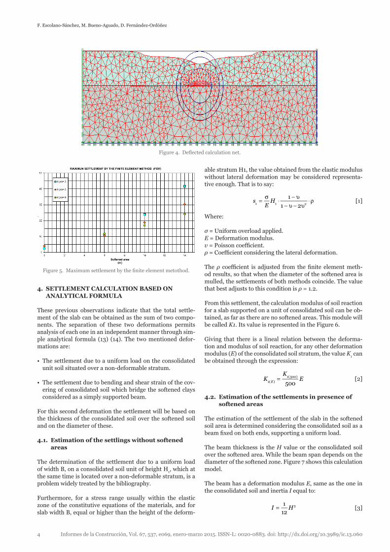
The observation of the deformation of these models indicates that the slab settlement has two components. The first one is due the general deformability of the consolidated soil, and the second one is due the presence of the softened area. The area of influence of this second settlement is over the pro-jection of the softened area. These two deformations can be clearly seen in the following graph (Figure 4).
Other conclusions from the analysis carried out are:
• All the deformation of the model is within the soil unit, both consolidated and softened. Deformations in the chalk rock unit are valueless.
• The general settlement of the slab outside the projection of the softened soil unit depends on the deformation char-acteristics of the consolidated soil and its thickness above bedrock (12).
The settlement on softened soil projection area depends on the diameter of the hollow and the thickness of the consoli-dated soil above the softened. In the following graph (Figure 5) this tendency can be seen in a quantitative manner. It can be observed that as the gap span (L) increases, or diameter of softened area, so does the settlement. In the same way, when the thickness of cover (H) increases, the settlement decreases.
In the previous graph (Figure 5), it was observed that for a fixed cover H thickness, the settlements increase on increas-ing the diameter of the softened area. The dip of the curve decreases for the greatest H values.
On the other hand, for small diameters, the greater part of the settlement is due to the thickness of consolidated clays and thus the settlements are greater for greater covers.
The estimation of the total settlement in the slab is based in the consideration of the natural ground as a semi elastic-plas-tic space, limited at a determined depth by a non-deformable stratum (6). The position of this stratum corresponds with the start of the competent substrate, while the deformation area corresponds with the unit of overlying soil and cavities from natural or anthropic.
In a first stage the estimation of the settlements in the slab is made by the finite element method (FEM) (7), with a model that allows analyzing the effect of the presence of softened areas. This method is often out of reach of the foundation recommendations gathered in a building geotechnical study, so from the observations made in this first model, a second method is proposed, which allows obtaining the values in a fast a simple way, with the guarantee of being within the a correct order of magnitude.
3. ESTIMATION OF THE MAXIMUM SETTLINGS BY THE FINITE ELEMENT METHOD (FEM)
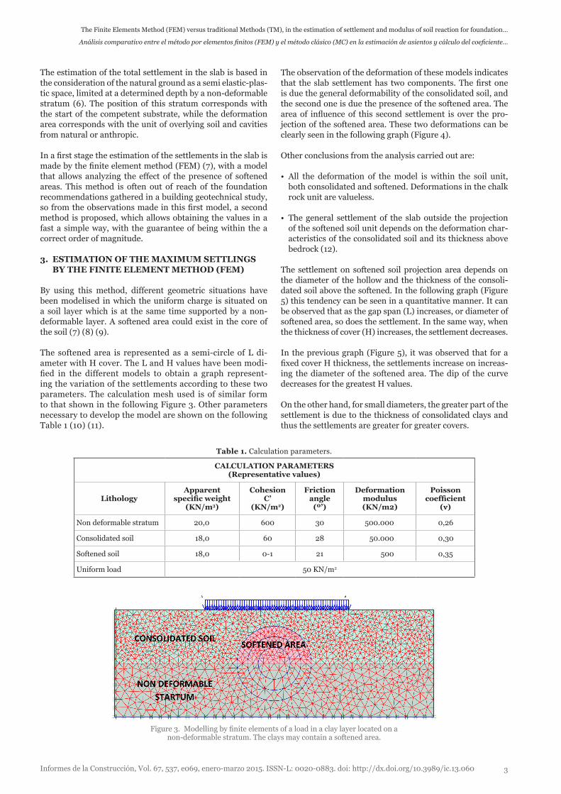
By using this method, different geometric situations have been modelised in which the uniform charge is situated on a soil layer which is at the same time supported by a non-deformable layer. A softened area could exist in the core of the soil (7) (8) (9).
The softened area is represented as a semi-circle of L di-ameter with H cover. The L and H values have been modi-fied in the different models to obtain a graph represent-ing the variation of the settlements according to these two parameters. The calculation mesh used is of similar form to that shown in the following Figure 3. Other parameters necessary to develop the model are shown on the following Table 1 (10) (11).
Figure 3. Modelling by finite elements of a load in a clay layer located on a non-deformable stratum. The clays may contain a softened area.
Table 1. Calculation parameters.
CALCULATION PARAMETERS(Representative values)
LithologyApparent
specific weight(KN/m3)
CohesionC’
(KN/m2)
Friction angle
(º’)
Deformation modulus(KN/m2)
Poisson coefficient
(ν)
Non deformable stratum 20,0 600 30 500.000 0,26
Consolidated soil 18,0 60 28 50.000 0,30
Softened soil 18,0 0-1 21 500 0,35
Uniform load 50 KN/m2
F. Escolano-Sánchez, M. Bueno-Aguado, D. Fernández-Ordóñez
Informes de la Construcción, Vol. 67, 537, e069, enero-marzo 2015. ISSN-L: 0020-0883. doi: http://dx.doi.org/10.3989/ic.13.0604
able stratum H1, the value obtained from the elastic modulus without lateral deformation may be considered representa-tive enough. That is to say:
1
1 21 1 2sEH=
σ⋅
− υ− υ − υ
⋅ρ [1]
Where:
σ = Uniform overload applied.E = Deformation modulus.υ = Poisson coefficient.ρ = Coefficient considering the lateral deformation.
The ρ coefficient is adjusted from the finite element meth-od results, so that when the diameter of the softened area is mulled, the settlements of both methods coincide. The value that best adjusts to this condition is ρ = 1.2.
From this settlement, the calculation modulus of soil reaction for a slab supported on a unit of consolidated soil can be ob-tained, as far as there are no softened areas. This module will be called K1. Its value is represented in the Figure 6.
Giving that there is a lineal relation between the deforma-tion and modulus of soil reaction, for any other deformation modulus (E) of the consolidated soil stratum, the value K
1 can
be obtained through the expression:
5001( )
1(500)KK
EE
= [2]
4.2. Estimation of the settlements in presence of softened areas
The estimation of the settlement of the slab in the softened soil area is determined considering the consolidated soil as a beam fixed on both ends, supporting a uniform load.
The beam thickness is the H value or the consolidated soil over the softened area. While the beam span depends on the diameter of the softened zone. Figure 7 shows this calculation model.
The beam has a deformation modulus E, same as the one in the consolidated soil and inertia I equal to:
1
123I H= [3]
4. SETTLEMENT CALCULATION BASED ON ANALYTICAL FORMULA
These previous observations indicate that the total settle-ment of the slab can be obtained as the sum of two compo-nents. The separation of these two deformations permits analysis of each one in an independent manner through sim-ple analytical formula (13) (14). The two mentioned defor-mations are:
• The settlement due to a uniform load on the consolidated unit soil situated over a non-deformable stratum.
• The settlement due to bending and shear strain of the cov-ering of consolidated soil which bridge the softened clays considered as a simply supported beam.
For this second deformation the settlement will be based on the thickness of the consolidated soil over the softened soil and on the diameter of these.
4.1. Estimation of the settlings without softened areas
The determination of the settlement due to a uniform load of width B, on a consolidated soil unit of height H
1, which at
the same time is located over a non-deformable stratum, is a problem widely treated by the bibliography.
Furthermore, for a stress range usually within the elastic zone of the constitutive equations of the materials, and for slab width B, equal or higher than the height of the deform-
Figure 4. Deflected calculation net.
Figure 5. Maximum settlement by the finite element metothod.

The Finite Elements Method (FEM) versus traditional Methods (TM), in the estimation of settlement and modulus of soil reaction for foundation…
Análisis comparativo entre el método por elementos finitos (FEM) y el método clásico (MC) en la estimación de asientos y cálculo del coeficiente…
Informes de la Construcción, Vol. 67, 537, e069, enero-marzo 2015. ISSN-L: 0020-0883. doi: http://dx.doi.org/10.3989/ic.13.060 5
And operating we get,
1 2
1 2
KrK K
K K=
+ [7]
This corresponds to the addition of two serial springs.
5. VERIFICATION OF THE ANALYTICAL METHOD FROM THE FEM METHOD
The validation of the analytical method proposed is made comparing its results with the results of the finite element model (15) (16). Figure 9 shows the results of both methods in the coordinate axes H and L previously defined.
The results indicate a good overlap between both methods. Particularly, the following matters are observed.
When there is no softened area, that is to say, when L = 0, both methods show almost the same results.
Both methods show the same tendency in the settlement growth. This means, for a constant value of H, the settle-ment increase when L increases as well. At the same time, the growth speed decreases when H increases.
The maximum differences between these two methods occur when the span (L) increases. These differences are due to the influence of the shape of the cavities on FEM.
The estimated settlements of the analytical method are the same, from a practical application point of view, or higher to the ones calculated with the FEM.
In view of these results it can be concluded that the analyti-cal method described obtains, chiefly in practical situations, values similar to those of Finite Elements Method.
Where these methods are not the same, the analytical method gives higher values of the modulus of soil reaction so that it gives way to stress in the foundation elements also higher and therefore it is a method which tends to decrease the risk of fracture of the slab or strap footings
The settlement of this beam due to the bending and the shear strain is:
384
(1 )
42
4 2
sL
EI
L
HE=
σ+σ + υ
[4]
Where σ represents the uniform work overload.
The modulus of soil reaction may be obtained from this rela-tion, as the quotient between the work overload and the total settlement
2K
s=σ
[5]
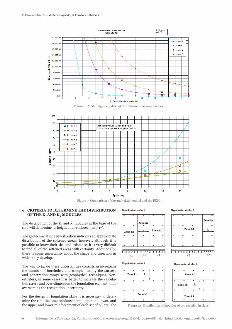
Figure 8 shows the modulus of soil reaction calculated from this expression, for different values of H and L.
As it happened with the K1 module, the K
2 module is propor-
tional to E, therefore for another deformation modulus is im-mediately obtained.
The total settlement in the softened soil area will be the addi-tion of settlement S
1 and S
2, so the modulus of soil reaction in
the softened soil area is:
1 2
Krs s
=σ+
[6]
Figure 6. Modulus of soil reaction for slabs on clayish soil.
Figure 7. Modelling calculation of the deformations over cavities.
F. Escolano-Sánchez, M. Bueno-Aguado, D. Fernández-Ordóñez
Informes de la Construcción, Vol. 67, 537, e069, enero-marzo 2015. ISSN-L: 0020-0883. doi: http://dx.doi.org/10.3989/ic.13.0606
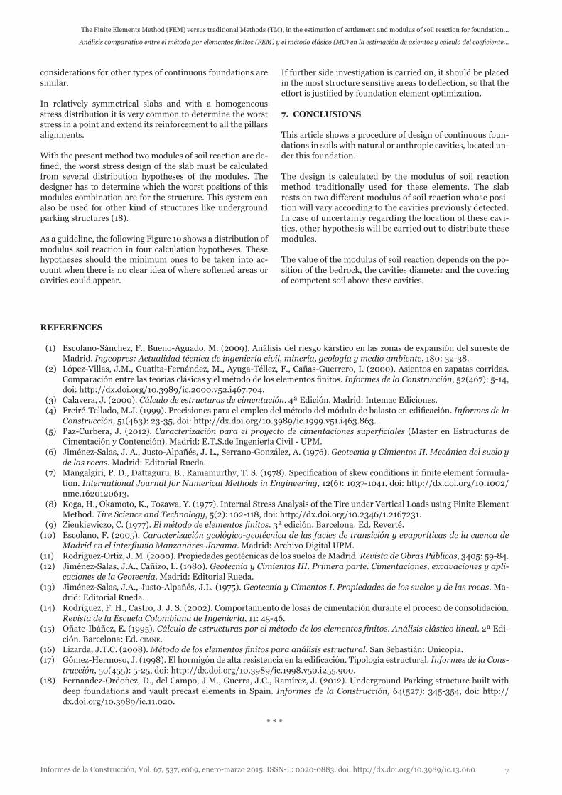
6. CRITERIA TO DETERMINE THE DISTRIBUTION OF THE K
1 AND K
R MODULES
The distribution of the K1 and K
r modules at the base of the
slab will determine its height and reinforcement (17).
The geotechnical side investigation indicates an approximate distribution of the softened areas; however, although it is possible to know their size and existence, it is very difficult to find all of the softened areas with certainty. Additionally, there is some uncertainty about the shape and direction in which they develop.
The way to tackle these uncertainties consists in increasing the number of boreholes, and complementing the surveys and penetration essays with geophysical techniques. Nev-ertheless, in some cases it is better to increase the calcula-tion stress and over-dimension the foundation element, thus overcoming the recognition uncertainty.
For the design of foundation slabs it is necessary to deter-mine the rim, the base reinforcement, upper and lower, and the upper and lower reinforcement of each set of pillars. The
Figure 8. Modelling calculation of the deformations over cavities.
Figure 9. Comparison of the analytical method and the FEM.
Figure 10. Distribution of modulus of soil reaction in slabs.
The Finite Elements Method (FEM) versus traditional Methods (TM), in the estimation of settlement and modulus of soil reaction for foundation…
Análisis comparativo entre el método por elementos finitos (FEM) y el método clásico (MC) en la estimación de asientos y cálculo del coeficiente…
Informes de la Construcción, Vol. 67, 537, e069, enero-marzo 2015. ISSN-L: 0020-0883. doi: http://dx.doi.org/10.3989/ic.13.060 7
REFERENCES
(1) Escolano-Sánchez, F., Bueno-Aguado, M. (2009). Análisis del riesgo kárstico en las zonas de expansión del sureste de Madrid. Ingeopres: Actualidad técnica de ingeniería civil, minería, geología y medio ambiente, 180: 32-38.
(2) López-Villas, J.M., Guatita-Fernández, M., Ayuga-Téllez, F., Cañas-Guerrero, I. (2000). Asientos en zapatas corridas. Comparación entre las teorías clásicas y el método de los elementos finitos. Informes de la Construcción, 52(467): 5-14, doi: http://dx.doi.org/10.3989/ic.2000.v52.i467.704.
(3) Calavera, J. (2000). Cálculo de estructuras de cimentación. 4ª Edición. Madrid: Intemac Ediciones. (4) Freiré-Tellado, M.J. (1999). Precisiones para el empleo del método del módulo de balasto en edificación. Informes de la
Construcción, 51(463): 23-35, doi: http://dx.doi.org/10.3989/ic.1999.v51.i463.863. (5) Paz-Curbera, J. (2012). Caracterización para el proyecto de cimentaciones superficiales (Máster en Estructuras de
Cimentación y Contención). Madrid: E.T.S.de Ingeniería Civil - UPM. (6) Jiménez-Salas, J. A., Justo-Alpañés, J. L., Serrano-González, A. (1976). Geotecnia y Cimientos II. Mecánica del suelo y
de las rocas. Madrid: Editorial Rueda. (7) Mangalgiri, P. D., Dattaguru, B., Ramamurthy, T. S. (1978). Specification of skew conditions in finite element formula-
tion. International Journal for Numerical Methods in Engineering, 12(6): 1037-1041, doi: http://dx.doi.org/10.1002/nme.1620120613.
(8) Koga, H., Okamoto, K., Tozawa, Y. (1977). Internal Stress Analysis of the Tire under Vertical Loads using Finite Element Method. Tire Science and Technology, 5(2): 102-118, doi: http://dx.doi.org/10.2346/1.2167231.
(9) Zienkiewiczo, C. (1977). El método de elementos finitos. 3ª edición. Barcelona: Ed. Reverté.(10) Escolano, F. (2005). Caracterización geológico-geotécnica de las facies de transición y evaporíticas de la cuenca de
Madrid en el interfluvio Manzanares-Jarama. Madrid: Archivo Digital UPM.(11) Rodríguez-Ortiz, J. M. (2000). Propiedades geotécnicas de los suelos de Madrid. Revista de Obras Públicas, 3405: 59-84.(12) Jiménez-Salas, J.A., Cañizo, L. (1980). Geotecnia y Cimientos III. Primera parte. Cimentaciones, excavaciones y apli-
caciones de la Geotecnia. Madrid: Editorial Rueda.(13) Jiménez-Salas, J.A., Justo-Alpañés, J.L. (1975). Geotecnia y Cimentos I. Propiedades de los suelos y de las rocas. Ma-
drid: Editorial Rueda.(14) Rodríguez, F. H., Castro, J. J. S. (2002). Comportamiento de losas de cimentación durante el proceso de consolidación.
Revista de la Escuela Colombiana de Ingeniería, 11: 45-46.(15) Oñate-Ibáñez, E. (1995). Cálculo de estructuras por el método de los elementos finitos. Análisis elástico lineal. 2ª Edi-
ción. Barcelona: Ed. cimne.(16) Lizarda, J.T.C. (2008). Método de los elementos finitos para análisis estructural. San Sebastián: Unicopia.(17) Gómez-Hermoso, J. (1998). El hormigón de alta resistencia en la edificación. Tipología estructural. Informes de la Cons-
trucción, 50(455): 5-25, doi: http://dx.doi.org/10.3989/ic.1998.v50.i255.900.(18) Fernandez-Ordoñez, D., del Campo, J.M., Guerra, J.C., Ramírez, J. (2012). Underground Parking structure built with
deep foundations and vault precast elements in Spain. Informes de la Construcción, 64(527): 345-354, doi: http://dx.doi.org/10.3989/ic.11.020.
* * *
If further side investigation is carried on, it should be placed in the most structure sensitive areas to deflection, so that the effort is justified by foundation element optimization.
7. CONCLUSIONS
This article shows a procedure of design of continuous foun-dations in soils with natural or anthropic cavities, located un-der this foundation.
The design is calculated by the modulus of soil reaction method traditionally used for these elements. The slab rests on two different modulus of soil reaction whose posi-tion will vary according to the cavities previously detected. In case of uncertainty regarding the location of these cavi-ties, other hypothesis will be carried out to distribute these modules.
The value of the modulus of soil reaction depends on the po-sition of the bedrock, the cavities diameter and the covering of competent soil above these cavities.
considerations for other types of continuous foundations are similar.
In relatively symmetrical slabs and with a homogeneous stress distribution it is very common to determine the worst stress in a point and extend its reinforcement to all the pillars alignments.
With the present method two modules of soil reaction are de-fined, the worst stress design of the slab must be calculated from several distribution hypotheses of the modules. The designer has to determine which the worst positions of this modules combination are for the structure. This system can also be used for other kind of structures like underground parking structures (18).
As a guideline, the following Figure 10 shows a distribution of modulus soil reaction in four calculation hypotheses. These hypotheses should the minimum ones to be taken into ac-count when there is no clear idea of where softened areas or cavities could appear.