Embed Size (px)
Citation preview

Flexible Input Deterministic Output (fido®) Instruction Set Reference Guide 32-Bit Real-Time Communications Controller September 4, 2008
IA222080723-01 http://www.Innovasic.com UNCONTROLLED WHEN PRINTED OR COPIED Customer Support: Page 1 of 193 1-888-824-4184
®
The fido1100® Instruction Set Reference Guide for the 32-Bit Real-Time Communications Controller
®

Flexible Input Deterministic Output (fido®) Instruction Set Reference Guide 32-Bit Real-Time Communications Controller September 4, 2008
IA222080723-01 http://www.Innovasic.com UNCONTROLLED WHEN PRINTED OR COPIED Customer Support: Page 2 of 193 1-888-824-4184
®
Copyright 2008 by Innovasic Semiconductor, Inc. Published by Innovasic Semiconductor, Inc.
3737 Princeton Drive NE, Suite 130, Albuquerque, NM 87107
fido®, fido1100®, and SPIDER are trademarks of Innovasic Semiconductor, Inc. I2C™ Bus is a trademark of Philips Electronics N.V. Motorola® is a registered trademark of Motorola, Inc.

Flexible Input Deterministic Output (fido®) Instruction Set Reference Guide 32-Bit Real-Time Communications Controller September 4, 2008
IA222080723-01 http://www.Innovasic.com UNCONTROLLED WHEN PRINTED OR COPIED Customer Support: Page 3 of 193 1-888-824-4184
®
TABLE OF CONTENTS
List of Figures ..................................................................................................................................3
List of Tables ...................................................................................................................................3 List of Instructions ...........................................................................................................................4 Conventions .....................................................................................................................................7 1. Overview .................................................................................................................................8
1.1 Data-Movement Instructions .........................................................................................8
1.2 Integer Arithmetic Operations .......................................................................................8 1.3 Logic Instructions ..........................................................................................................9 1.4 Shift and Rotate Instructions .........................................................................................9
1.5 Bit Manipulation Instructions ........................................................................................9 1.6 Binary-Coded Decimal Instructions ............................................................................10 1.7 Program Control Instructions ......................................................................................10 1.8 System Control Instructions ........................................................................................10
1.9 Instruction Attributes ...................................................................................................10 1.10 Instruction Format .......................................................................................................10
1.11 Core Addressing Modes Summary .............................................................................11 1.12 Instruction Format for Single Effective Address Instruction Word ............................13 1.13 Format for the Brief Extension Word..........................................................................13
1.14 Format for the Full Extension Word ...........................................................................14 2. Instruction Descriptions ........................................................................................................17
3. For Additional Information .................................................................................................190 Index ............................................................................................................................................191
LIST OF FIGURES
Figure 1. Shift and Rotate Instructions Diagram ..........................................................................39
LIST OF TABLES
Table 1. Instruction Word General Format ...................................................................................11 Table 2. Core Addressing Modes Summary .................................................................................11 Table 3. Instruction Format for Single Effective Address Instruction Word ................................13 Table 4. Instruction Format for Brief Instruction Word ................................................................14
Table 5. Format for the Full Extension Word ...............................................................................15

Flexible Input Deterministic Output (fido®) Instruction Set Reference Guide 32-Bit Real-Time Communications Controller September 4, 2008
IA222080723-01 http://www.Innovasic.com UNCONTROLLED WHEN PRINTED OR COPIED Customer Support: Page 4 of 193 1-888-824-4184
®
LIST OF INSTRUCTIONS
ABCD—Add Decimal with Extend
ADD—Add ADDA—Add Address ADDI—Add Immediate ADDQ—Add Quick ADDX—Add Extended
AND—And ANDI—And Immediate ANDI to CCR—And Immediate to Condition Code Register
ANDI to SR—And Immediate to Status Register ASL/ASR—Arithmetic Shift BCC—Branch Conditionally BCHG—Test a Bit and Change
BCLR—Test a Bit and Clear BGND—Enter Background Mode
BKPT—Software Breakpoint BRA—Branch Always BSET—Test a Bit and Set
BSR—Branch to Subroutine BTST—Test a Bit
CHK—Check Register Against Bounds CHK2—Check Register Against Bounds
CLR—Clear an Operand CMP—Compare
CMP2—Compare Register Against Bounds CMPA—Compare Address CMPI—Compare Immediate
CMPM—Compare Memory DBCC—Test Condition, Decrement and Branch DIVS/DIVSL—Signed Divide
DIVU/DIVUL—Unsigned Divide EOR—Exclusive OR EORI—Exclusive OR Immediate EORI to CCR—Exclusive OR Immediate to Condition Code Register
EORI to SR—Exclusive OR Immediate to Status Register EXG—Exchange Registers EXT/EXTB—Sign Extend
ILLEGAL—Take Illegal Instruction Trap JMP—Jump JSR—Jump to Subroutine

Flexible Input Deterministic Output (fido®) Instruction Set Reference Guide 32-Bit Real-Time Communications Controller September 4, 2008
IA222080723-01 http://www.Innovasic.com UNCONTROLLED WHEN PRINTED OR COPIED Customer Support: Page 5 of 193 1-888-824-4184
®
LEA—Load Effective Address LINK—Link and Allocate
LPSTOP—Low Power Stop LSL/LSR—Logical Shift MOVE—Move Data from Source to Destination MOVEA—Move Data from Source to Destination Address Register MOVEC—Move Control Register
MOVEM—Move Multiple Registers MOVEP—Move Peripheral Data MOVEQ—Move Quick MOVES—Move Address Space
MOVE from CCR —Move Data from the Condition Code Register MOVE to CCR —Move Data to the Condition Code Register MOVE from SR —Move Data from the Status Register
MOVE USP—Move User Stack Pointer MULS—Signed Multiply
MULU—Unsigned Multiply NBCD—Negate Decimal with Extend NEG—Negate
NEGX—Negate with Extend NOP—No Operation
NOT—Logical Complement OR—Inclusive Logical OR ORI—Inclusive OR Immediate
ORI to CCR—Inclusive OR Immediate to Condition Code Register
ORI to SR—Inclusive OR Immediate to Status Register PEA—Push Effective Address RESET—Reset External Devices
ROL/ROR—Rotate Without Extend ROXL/ROXR—Rotate With Extend RTD—Return and Deallocate
RTE—Return from Exception RTR—Return and Restore Condition Codes RTS—Return from Subroutine SBCD—Subtract Decimal with Extend SCC—Set According to Condition Code
SLEEP—Sleep Current Context STOP—Load Status Register and Stop
SUB—Subtract SUBA—Subtract Address SUBI—Subtract Immediate SUBQ—Subtract Quick

Flexible Input Deterministic Output (fido®) Instruction Set Reference Guide 32-Bit Real-Time Communications Controller September 4, 2008
IA222080723-01 http://www.Innovasic.com UNCONTROLLED WHEN PRINTED OR COPIED Customer Support: Page 6 of 193 1-888-824-4184
®
SUBX—Subtract Extended SWAP—Swap Register Halves
TAS—Test and Set an Operand TRAP—Trap TRAPCC—Trap on Condition TRAPV—If V then Trap TRAPX—Trap to Master Context_0
TST—Test an Operand UNLK—Unlink

Flexible Input Deterministic Output (fido®) Instruction Set Reference Guide 32-Bit Real-Time Communications Controller September 4, 2008
IA222080723-01 http://www.Innovasic.com UNCONTROLLED WHEN PRINTED OR COPIED Customer Support: Page 7 of 193 1-888-824-4184
®
CONVENTIONS
Arial Bold Designates headings, figure captions, and table captions.
Blue Designates hyperlinks.
Courier Designates code text.
Italics Designates emphasis or caution related to nearby information.

Flexible Input Deterministic Output (fido®) Instruction Set Reference Guide 32-Bit Real-Time Communications Controller September 4, 2008
IA222080723-01 http://www.Innovasic.com UNCONTROLLED WHEN PRINTED OR COPIED Customer Support: Page 8 of 193 1-888-824-4184
®
1. Overview
This document describes the fido1100 instruction set for the fido1100 communications controller
and includes machine functions for the following operations:
Data movement
Arithmetic operations
Logical operations
Shifts and rotates
Bit manipulation
Binary-Coded Decimal (BCD) arithmetic
Program control
System control
The following subsections summarize the fido1100 instructions available for these operations.
1.1 Data-Movement Instructions
The MOVE instruction is the basic means of transferring and storing address and data. MOVE
instructions transfer byte, word, and long-word operands from memory to memory, memory to
register, register to memory, and register to register. Address movement instructions (MOVE Or
MOVEA) transfer word and long-word operands and ensure that only valid address
manipulations are executed.
In addition to the general MOVE instructions, there are several specific data-movement
instructions—move multiple registers (MOVEM), move peripheral data (MOVEP), move quick
(MOVEQ), exchange registers (EXG), load effective address (LEA), push effective address
(PEA), link stack (LINK), and unlink stack (UNLK).
1.2 Integer Arithmetic Operations
The arithmetic operations include the four basic operations of add (ADD), subtract (SUB),
multiply (MULS—Signed Multiply, MULU—Unsigned Multiply), and divide (DIVS/DIVSL—
Signed Divide, DIVU/DIVUL—Unsigned Divide), as well as arithmetic compare (CMP,
CMPM, CMP2), clear (CLR), and negate (NEG). The instruction set includes ADD, CMP, and
SUB instructions for both address and data operations with all operand sizes valid for data
operations. Address operands consist of 16 or 32 bits. The clear and negate instructions apply to
all sizes of data operands.
Signed and unsigned multiply and divide instructions include:

Flexible Input Deterministic Output (fido®) Instruction Set Reference Guide 32-Bit Real-Time Communications Controller September 4, 2008
IA222080723-01 http://www.Innovasic.com UNCONTROLLED WHEN PRINTED OR COPIED Customer Support: Page 9 of 193 1-888-824-4184
®
Word multiply to produce a long-word product
Long-word multiply to produce a long-word or quad-word product
Division of a long-word dividend by a word divisor (word quotient and word remainder)
Division of a long-word or quad-word dividend by a long-word divisor (long-word
quotient and long-word remainder)
A set of extended instructions provides multi-precision and mixed-size arithmetic. These
instructions are add extended (ADDX), subtract extended (SUBX), sign extend (EXT/EXTB),
and negate binary with extend (NEGX).
1.3 Logic Instructions
The logical operation instructions (AND, OR, EOR, and NOT) perform logical operations with
all sizes of integer data operands. A similar set of immediate instructions (ANDI, ORI, and
EORI) provide these logical operations with all sizes of immediate data. The TST instruction
arithmetically compares the operand with zero, placing the result in the condition code register.
1.4 Shift and Rotate Instructions
The arithmetic shift instructions, ASL/ASR, and logical shift instructions, LSL/LSR, provide
shift operations in both directions. The ROL/ROR and ROXL/ROXR instructions perform rotate
(circular shift) operations, with and without the extend bit. All shift and rotate operations can be
performed on either registers or memory.
Register shift and rotate operations shift all operand sizes. The shift count may be specified in
the instruction operation word (to shift from one to eight places) or in a register (modulo 64-shift
count).
Memory shift and rotate operations shift word-length operands one bit-position only. The
SWAP instruction exchanges the 16-bit halves of a register. Performance of shift/rotate
instructions is enhanced so that use of the ROL/ROR instructions with a shift count of eight
allows fast byte swapping.
1.5 Bit Manipulation Instructions
Bit manipulation operations are accomplished using the following instructions: bit test (BTST),
bit test and set (BSET), bit test and clear (BCLR), and bit test and change (BCHG). All bit
manipulation operations can be performed either on registers or on memory. The bit number is
specified as immediate data or in a data register. Register operands are 32 bits long, and memory
operands are 8 bits long.

Flexible Input Deterministic Output (fido®) Instruction Set Reference Guide 32-Bit Real-Time Communications Controller September 4, 2008
IA222080723-01 http://www.Innovasic.com UNCONTROLLED WHEN PRINTED OR COPIED Customer Support: Page 10 of 193 1-888-824-4184
®
1.6 Binary-Coded Decimal Instructions
Five instructions support operations on Binary-Coded Decimal (BCD) numbers. The arithmetic
operations on packed BCD numbers are add decimal with extend (ABCD), subtract decimal with
extend (SBCD), and negate decimal with extend (NBCD).
1.7 Program Control Instructions
A set of subroutine call and return instructions and conditional and unconditional branch
instructions perform program control operations.
1.8 System Control Instructions
Privileged instructions, trapping instructions, and instructions that use or modify the condition
code register provide system control operations. All of these instructions cause the processor to
flush the instruction pipeline.
1.9 Instruction Attributes
The attributes line specifies the size of the operands of an instruction. When an instruction can
use operands of more than one size, a suffix is used with the mnemonic of the instruction:
.B Byte
.W Word
.L Long word
In instruction descriptions, the Condition Codes are defined as follows:
X—extend bit
N—negative bit
Z—zero bit
V—overflow bit
C—Carry Bit
1.10 Instruction Format
All instructions consist of at least one word. Some instructions can have as many as seven
words, as shown in Table 1. The first word of the instruction, called the ―operation word,‖
specifies instruction length and the operation to be performed. The remaining words, called
―extension words,‖ further specify the instruction and operands. These words may be immediate
operands, extensions to the effective address mode specified in the operation word, branch
displacements, bit number, special register specifications, trap operands, or argument counts.

Flexible Input Deterministic Output (fido®) Instruction Set Reference Guide 32-Bit Real-Time Communications Controller September 4, 2008
IA222080723-01 http://www.Innovasic.com UNCONTROLLED WHEN PRINTED OR COPIED Customer Support: Page 11 of 193 1-888-824-4184
®
Table 1. Instruction Word General Format
5 0
Operation Word (one word, specifies operation and modes)
Special Operand Specifiers (if any, one or two words)
Immediate Operand or Source Address Extension
(if any, one to three words)
Destination Effective Address Extension (if any, one to three words)
Besides the operation code, which specifies the function to be performed, an instruction defines
the location of every operand for the function. Instructions specify an operand location in one of
three ways:
Register Specification—A register field of the instruction contains the number of the
register.
Effective Address—An Effective-Address field of the instruction contains address mode
information.
Implicit Reference—The definition of an instruction implies the use of specific registers.
The register field within an instruction specifies the register to be used. Other fields within the
instruction specify whether the register is an address or data register and how it is used.
1.11 Core Addressing Modes Summary
Table 2 summarizes the various addressing modes of the fido1100 architecture:
Table 2. Core Addressing Modes Summary
Description Operation Syntax mode reg
No. of Ext
Words Notes
Data Register Direct EA=Dn Dn 000 n 0 –
Address Register Direct
EA=An An 001 n 0 –
Address Register Indirect
EA=(An) (An) 010 n 0 –
Address Register Indirect with Postincrement
EA=(An), An=An+Size (An)+ 011 n 0 4
Address Register Indirect with Predecrement
An=An-Size, EA=(An) -(An) 100 n 0 4

Flexible Input Deterministic Output (fido®) Instruction Set Reference Guide 32-Bit Real-Time Communications Controller September 4, 2008
IA222080723-01 http://www.Innovasic.com UNCONTROLLED WHEN PRINTED OR COPIED Customer Support: Page 12 of 193 1-888-824-4184
®
Table 2. Core Addressing Modes Summary (Continued)
Description Operation Syntax mode reg
No. of Ext
Words Notes
Address Register Indirect with Displacement
EA=(An)+d16 (d16,An) 101 n 1 3
Address Register Indirect with Index (8-bit displacement)
EA=(An)+(Xn*Scale) +d8
(d8,An,Xn.Size *Scale)
110 n 1 1,4,5
Address Register Indirect with Index (base displacement)
EA=(An)+(Xn*Scale) +bd
(bd,An,Xn.Size *Scale)
110 n 1, 2 or 3
2,4,5
Program Counter Indirect with Displacement
EA=(PC)+d16 (d16,PC) 111 010 1 3
Program Counter Indirect with Index (8-bit displacement)
EA=(PC)+(Xn*Scale) +d8
(d8,PC,Xn.Size *Scale)
111 011 1 1,4,5
Program Counter Indirect with Index (base displacement)
EA=(PC)+(Xn*Scale) +bd
(bd,PC,Xn.Size *Scale)
111 011 1, 2 or 3
2,4,5
Absolute Short Address
EA given (xxx).W 111 000 1 7
Absolute Long Address
EA given (xxx).L 111 001 2 7
Immediate no EA required #xxx 111 100 1 or 2 6
Notes:
1. Brief Format Extension Word contains index register indicator, scale, and 8-bit
displacement.
2. Full Format Extension Word contains index register indicator, scale, and 8-bit
displacement fixed at zero. Second and third extension words are optional and contain
16-bit or 32-bit base displacement.
3. Extension word is simply the 16-bit displacement and will be sign-extended to 32 bits
before being used.
4. Size = 1, 2, or 4.
5. Scale = 1, 2, 4, or 8.
6. Immediate data provided as one or two extension words. Contains 8-, 16-, or 32-bit data.
7. Extension word(s) will simply contain the operand’s effective address. One extension
word (16 bits) will be sign-extended to 32-bit address, and two extension words will
directly specify the address.

Flexible Input Deterministic Output (fido®) Instruction Set Reference Guide 32-Bit Real-Time Communications Controller September 4, 2008
IA222080723-01 http://www.Innovasic.com UNCONTROLLED WHEN PRINTED OR COPIED Customer Support: Page 13 of 193 1-888-824-4184
®
Additional Details:
Full Format Extension Word contains the following bits (among others):
– BS Bit—Allows the base register (used above as An, Dn, or PC) to be suppressed.
This part of the EA calculation will have an effective value of zero.
– IS Bit—Allows the index register to be suppressed. This part of the EA calculation
will have an effective value of zero.
– BD Size Bits—Setting these to 00 allows the base displacement to be suppressed.
This part of the EA calculation will have an effective value of zero.
– I/IS Bits—Used by memory indirect addressing modes. For CPU32 should always be
000. If when IS Bit is set to a ―1,‖ setting this field to a non-zero value will cause an
illegal instruction exception.
– Of the various items that can be suppressed, at least one field must be active and not
suppressed.
1.12 Instruction Format for Single Effective Address Instruction Word
This instruction format is used when the instruction only specifies a single effective address and
requires zero extension words. One example is the LEA instruction. The effective address field
of the instruction op-code is sufficient to specify fully the source of the effective address. The
general format is provided in Table 3.
Table 3. Instruction Format for Single Effective Address Instruction Word
15 14 13 12 11 10 9 8 7 6 5 4 3 2 1 0
Op-Code Effective Address
X X X X X X X X X X Mode Register
The instruction op-code specifies whether the selected register is an address register or a data
register and how the register is to be used.
1.13 Format for the Brief Extension Word
This is used by instructions that cannot use the single effective address instruction word format
but only require a single extension word to specify fully the source of the effective address. One
type of addressing mode would be instructions that are using an indexed addressing mode with
an 8-bit displacement. For example:
add.l 0x11(a1,a2.w*4),d1
or
add.l (0x11,a1,a2.w*4),d1

Flexible Input Deterministic Output (fido®) Instruction Set Reference Guide 32-Bit Real-Time Communications Controller September 4, 2008
IA222080723-01 http://www.Innovasic.com UNCONTROLLED WHEN PRINTED OR COPIED Customer Support: Page 14 of 193 1-888-824-4184
®
This uses address register indirect with index (8-bit displacement) and generates the following
op-code followed by the brief extension word (both in hex):
D2B1 A411
The general format is provided in Table 4.
Table 4. Instruction Format for Brief Instruction Word
15 14 13 12 11 10 9 8 7 6 5 4 3 2 1 0
D/A Register W/L Scale 0 Displacement
Where:
D/A—Index register type
– 0—Dn
– 1—An
Register—Index register number
W/L—Word/Long Word Size
– 0—16-bit word sign-extended to 32 bits
– 1—32-bit long word used as is
Scale—Scale factor
– 00—0
– 01—1
– 10—2
– 11—4
Displacement—8-bit displacement value, can be zero
1.14 Format for the Full Extension Word
This is used by instructions that cannot use either the single effective address-instruction word
format or the brief extension word format. This is because it requires multiple extension words
to specify fully the source of the effective address. One type of addressing mode would be
instructions that are using an indexed addressing mode with a 16-bit or 32-bit displacement. For
example:
add.l 0x1111(a1,a2.w*4),d1
or
add.l (0x1111,a1,a2.w*4),d1

Flexible Input Deterministic Output (fido®) Instruction Set Reference Guide 32-Bit Real-Time Communications Controller September 4, 2008
IA222080723-01 http://www.Innovasic.com UNCONTROLLED WHEN PRINTED OR COPIED Customer Support: Page 15 of 193 1-888-824-4184
®
This uses address register indirect with index (16-bit base displacement) and generates the
following op-code followed by the full extension word and finally the 16-bit displacement value
(all in hex):
D2B1 A520 1111
Another example is:
add.l 0x22221111(a1,a2.w*4),d1
or
add.l (0x22221111,a1,a2.w*4),d1
This uses address register indirect with index (32-bit base displacement) and generates the
following op-code followed by the full extension word and finally the 32-bit displacement value
(all in hex):
D2B1 A530 2222 1111
The general format is provided in Table 5.
Table 5. Format for the Full Extension Word
15 14 13 12 11 10 9 8 7 6 5 4 3 2 1 0
D/A Register W/L Scale 1 BS IS BD Size 0 I/IS
Base displacement (0, 1, or 2 words)
Where:
D/A—Index register type
– 0—Dn
– 1—An
Register—Index register number
W/L—Word/Long Word Size
– 0—16-bit word sign-extended to 32 bits
– 1—32-bit long word used as is
Scale—Scale factor
– 00—0
– 01—1
– 10—2
– 11—4

Flexible Input Deterministic Output (fido®) Instruction Set Reference Guide 32-Bit Real-Time Communications Controller September 4, 2008
IA222080723-01 http://www.Innovasic.com UNCONTROLLED WHEN PRINTED OR COPIED Customer Support: Page 16 of 193 1-888-824-4184
®
BS—Base Register Suppress
– 0—Base register added
– 1—Base register suppressed
IS—Index Suppress
– 0—Evaluate and add index operand
– 1—Suppress index operand
BD Size—Base Displacement Size
– 00—Reserved (will cause an illegal instruction exception)
– 01—Null displacement
– 10—Word Displacement
– 11—Long-Word Displacement
I/IS—Index/Indirect Selection
– Not used by fido1100, should always be 000, if IS = 1 and this not 000, will cause an
illegal instruction exception
Base displacement—16-bit or 32-bit displacement value (optional)

Flexible Input Deterministic Output (fido®) Instruction Set Reference Guide 32-Bit Real-Time Communications Controller September 4, 2008
IA222080723-01 http://www.Innovasic.com UNCONTROLLED WHEN PRINTED OR COPIED Customer Support: Page 17 of 193 1-888-824-4184
®
2. Instruction Descriptions
Descriptions of the fido1100 instructions, presented alphabetically, are given on the following
pages. Except where indicated, the following notation is used:
Data Immediate data from an instruction
Destination Destination contents
Source Source contents
Vector Location of exception vector
An Any address register (A7 to A0)
Ax, Ay Address registers used in computation
Dn Any data register (D7 to D0)
Rc Control register (VBR, SFC, DFC)
Rn Any address or data register
Dh, Dl Data registers, high- and low-order 32 bits of product
Dr, Dq Data registers, division remainder, division quotient
Dx, Dy Data registers, used in computation
Dym, Dyn Data registers, table interpolation values
Xn Index register
[An] Address extension
cc Condition code
d# Displacement (e.g., ―d16‖ is a 16-bit displacement)
<ea> Effective address
#<data> Immediate data; a literal integer
label Assembly program label
list List of registers (e.g., ―D3–D0‖)
[...] Bits of an operand (e.g., ―[7]‖ is Bit 7, ―[31–24]‖ are Bits 31 to 24)
(...) Contents of a referenced location (e.g., ―(Rn)‖ refers to the contents of Rn)
PC Program counter
SP Active stack pointer
SR Status register
SSP Supervisor stack pointer
USP User stack pointer
FC Function code
DFC Destination function code register
SFC Source function code register
+ Addition or post increment
− Subtraction or predecrement
/ Division or conjunction
* Multiplication
= Equal to
Not equal to
> Greater than

Flexible Input Deterministic Output (fido®) Instruction Set Reference Guide 32-Bit Real-Time Communications Controller September 4, 2008
IA222080723-01 http://www.Innovasic.com UNCONTROLLED WHEN PRINTED OR COPIED Customer Support: Page 18 of 193 1-888-824-4184
®
Greater than or equal to
< Less than
Less than or equal to
& Boolean AND | Boolean OR
^ Boolean XOR (exclusive OR)
BCD Binary coded decimal, indicated by subscript (e.g., Source10 is a BCD source
operand)
LSW Least significant word
MSW Most significant word
{R/W} Read/write indicator

Flexible Input Deterministic Output (fido®) Instruction Set Reference Guide 32-Bit Real-Time Communications Controller September 4, 2008
IA222080723-01 http://www.Innovasic.com UNCONTROLLED WHEN PRINTED OR COPIED Customer Support: Page 19 of 193 1-888-824-4184
ABCD—Add Decimal with Extend
®
ABCD—Add Decimal with Extend
Assembler ABCD Dy, Dx
Syntax: ABCD – (Ay), – (Ax)
Operation: Source10 + Destination10 + X bit → Destination
Attributes: Size = byte
Privileged: No
Condition Codes:
X—Set the same as Carry Bit
N—Undefined
Z—Cleared if result is non-zero; unchanged otherwise
V—Undefined
C—Set if decimal carry was generated; cleared otherwise
Note: Normal programming use of this instruction is to set the Z Bit prior to
performing this operation. This allows the Z Bit to be tested during multi-
precision operations.
Instruction Format:
15 14 13 12 11 10 9 8 7 6 5 4 3 2 1 0
Op-Code Effective Address
1 1 0 0 Destination Register 1 0 0 0 0 R/M Source Register
Where:
Destination Register—Specifies either a data or an address register as the location of the
destination operand.
Register/Memory (R/M):
– 0—Operands are addresses as Dn,Dn
– 1—Operands are addresses as -(An),-(An)
Source Register—Specifies either a data or an address register as the location of the
source operand.
Effective-Address fields are as per Instruction Single Word Format and address mode
tables (see Table 1, Core Addressing Modes Summary).

Flexible Input Deterministic Output (fido®) Instruction Set Reference Guide 32-Bit Real-Time Communications Controller September 4, 2008
IA222080723-01 http://www.Innovasic.com UNCONTROLLED WHEN PRINTED OR COPIED Customer Support: Page 20 of 193 1-888-824-4184
ABCD—Add Decimal with Extend
®
This instruction only uses two addressing modes (determined by the R/M Bit):
Data Register Direct—Dn,Dn (both source and destination are data registers).
Address Register Indirect with Predecrement—-(An),-(An) (both source and destination
are pointed to by address registers).

Flexible Input Deterministic Output (fido®) Instruction Set Reference Guide 32-Bit Real-Time Communications Controller September 4, 2008
IA222080723-01 http://www.Innovasic.com UNCONTROLLED WHEN PRINTED OR COPIED Customer Support: Page 21 of 193 1-888-824-4184
ADD—Add
®
ADD—Add
Assembler ADD <ea>, Dn
Syntax: ADD Dn, <ea>
Operation: Source + Destination → Destination
Attributes: Size = byte, word or long
Privileged: No
Condition Codes:
X—Set the same as Carry Bit
N—Set if result is negative; cleared otherwise
Z—Set if result is zero; cleared otherwise
V—Set if overflow is generated; cleared otherwise
C—Set if carry was generated; cleared otherwise
Instruction Format:
15 14 13 12 11 10 9 8 7 6 5 4 3 2 1 0
Op-Code Effective Address
1 1 0 1 Register Opmode Mode Register
Where:
Register Field—Specifies any one of the eight data registers.
Opmode Field—Specifies whether the effective address is the source or the destination as
follows:
Operation Byte Word Long
(EA) + (Dn) → (Dn) 000 001 010
(Dn) + (EA) → (EA) 100 101 110
Effective-Address fields are as per Instruction Single Word Format and address mode
tables (see Table 2, Core Addressing Modes Summary).

Flexible Input Deterministic Output (fido®) Instruction Set Reference Guide 32-Bit Real-Time Communications Controller September 4, 2008
IA222080723-01 http://www.Innovasic.com UNCONTROLLED WHEN PRINTED OR COPIED Customer Support: Page 22 of 193 1-888-824-4184
ADD—Add
®
Addressing modes for source operand:
Addressing Mode Mode Field Register Field Applies? Notes
Dn 000 N Yes –
An 001 N Yes Word and long word only
(An) 010 N Yes –
(An)+ 011 N Yes –
-(An) 100 N Yes –
(d16,An) 101 N Yes –
(d8,An,Xn.Size*Scale) 110 N Yes –
(bd,An,Xn.Size*Scale) 110 N Yes –
(d16,PC) 111 010 Yes –
(d8,PC,Xn.Size*Scale) 111 011 Yes –
(bd,PC,Xn.Size*Scale) 111 011 Yes –
(xxx).W 111 000 Yes –
(xxx).L 111 001 Yes –
#xxx 111 100 Yes ADDI and ADDQ are used if the source is immediate data
Addressing modes for destination operand:
Addressing Mode Mode Field Register Field Applies? Notes
Dn 000 N – –
An 001 N – ADDA is used when the destination is an address register.
(An) 010 N Yes –
(An)+ 011 N Yes –
-(An) 100 N Yes –
(d16,An) 101 N Yes –
(d8,An,Xn.Size*Scale) 110 N Yes –
(bd,An,Xn.Size*Scale) 110 N Yes –
(d16,PC) 111 010 – –
(d8,PC,Xn.Size*Scale) 111 011 – –
(bd,PC,Xn.Size*Scale) 111 011 – –
(xxx).W 111 000 Yes –
(xxx).L 111 001 Yes –
#xxx 111 100 – –

Flexible Input Deterministic Output (fido®) Instruction Set Reference Guide 32-Bit Real-Time Communications Controller September 4, 2008
IA222080723-01 http://www.Innovasic.com UNCONTROLLED WHEN PRINTED OR COPIED Customer Support: Page 23 of 193 1-888-824-4184
ADDA—Add Address
®
ADDA—Add Address
Assembler ADDA <ea> An
Syntax:
Operation: Source + Destination → Destination
Attributes: Size = word or long
Privileged: No
Condition Codes:
X—Not affected
N—Not affected
Z—Not affected
V—Not affected
C—Not affected
Instruction Format: 15 14 13 12 11 10 9 8 7 6 5 4 3 2 1 0
Op-Code Effective Address
1 1 0 1 Register Opmode Mode Register
Where:
Register Field—Specifies any one of the eight address registers as the destination.
Opmode Field—Specifies the size of the operand:
– 011—Word operation. The source operand is sign-extended to a long and the
operation performed on the address register uses all 32 bits.
– 111—Long operation.
Effective-Address fields are as per Instruction Single Word Format and address mode
tables (see Table 3, Core Addressing Modes Summary) and always indicate a source
operand.

Flexible Input Deterministic Output (fido®) Instruction Set Reference Guide 32-Bit Real-Time Communications Controller September 4, 2008
IA222080723-01 http://www.Innovasic.com UNCONTROLLED WHEN PRINTED OR COPIED Customer Support: Page 24 of 193 1-888-824-4184
ADDA—Add Address
®
Addressing modes for source operand: Addressing Mode Mode Field Register Field Applies? Notes
Dn 000 N Yes –
An 001 N Yes –
(An) 010 N Yes –
(An)+ 011 N Yes –
-(An) 100 N Yes –
(d16,An) 101 N Yes –
(d8,An,Xn.Size*Scale) 110 N Yes –
(bd,An,Xn.Size*Scale) 110 N Yes –
(d16,PC) 111 010 Yes –
(d8,PC,Xn.Size*Scale) 111 011 Yes –
(bd,PC,Xn.Size*Scale) 111 011 Yes –
(xxx).W 111 000 Yes –
(xxx).L 111 001 Yes –
#xxx 111 100 Yes –

Flexible Input Deterministic Output (fido®) Instruction Set Reference Guide 32-Bit Real-Time Communications Controller September 4, 2008
IA222080723-01 http://www.Innovasic.com UNCONTROLLED WHEN PRINTED OR COPIED Customer Support: Page 25 of 193 1-888-824-4184
ADDI—Add Immediate
®
ADDI—Add Immediate
Assembler ADDI #<data>, <ea>
Syntax:
Operation: Immediate Data + Destination → Destination
Attributes: Size = byte, word or long
Privileged: No
Condition Codes:
X—Set same as Carry Bit
N—Set if result is negative; cleared otherwise
Z—Set if result is zero; cleared otherwise
V—Set if overflow is generated; cleared otherwise
C—Set if carry was generated; cleared otherwise
Instruction Format: 15 14 13 12 11 10 9 8 7 6 5 4 3 2 1 0
Op-Code Effective Address
0 0 0 0 0 1 1 0 Size Mode Register
Word Data (16 Bits) Byte Data (8 Bits)
Long Data (32 Bits)
Where:
Size Field (size of immediate data must match operand size):
– 00—Byte operation → data is low-order byte of immediate word.
– 01—Word operation → data is the entire immediate word.
– 10—Long operation → data is in the next two immediate words.
Effective-Address fields are as per Instruction Single Word Format and address mode
tables (see Table 4, Core Addressing Modes Summary) and always indicate a destination
operand.

Flexible Input Deterministic Output (fido®) Instruction Set Reference Guide 32-Bit Real-Time Communications Controller September 4, 2008
IA222080723-01 http://www.Innovasic.com UNCONTROLLED WHEN PRINTED OR COPIED Customer Support: Page 26 of 193 1-888-824-4184
ADDI—Add Immediate
®
Addressing modes for destination operand:
Addressing Mode Mode Field Register Field Applies? Notes
Dn 000 N Yes –
An 001 N – –
(An) 010 N Yes –
(An)+ 011 N Yes –
-(An) 100 N Yes –
(d16,An) 101 N Yes –
(d8,An,Xn.Size*Scale) 110 N Yes –
(bd,An,Xn.Size*Scale) 110 N Yes –
(d16,PC) 111 010 – –
(d8,PC,Xn.Size*Scale) 111 011 – –
(bd,PC,Xn.Size*Scale) 111 011 – –
(xxx).W 111 000 Yes –
(xxx).L 111 001 Yes –
#xxx 111 100 – –

Flexible Input Deterministic Output (fido®) Instruction Set Reference Guide 32-Bit Real-Time Communications Controller September 4, 2008
IA222080723-01 http://www.Innovasic.com UNCONTROLLED WHEN PRINTED OR COPIED Customer Support: Page 27 of 193 1-888-824-4184
ADDQ—Add Quick
®
ADDQ—Add Quick
Assembler ADDQ #<data>, <ea>
Syntax:
Operation:
Immediate Data + Destination → Destination
– Immediate data is stored as a part of the instruction word (three bits) and can range
from 1 to 8.
Attributes:
Size = byte, word or long
– When the destination operand is a data register or is in memory the size can be byte,
word, or long word.
– When the destination operand is an address register size is word or long word only.
– When adding to address registers the Condition Codes are not altered and entire
register is used regardless of operand size.
Privileged: No
Condition Codes:
X—Set same as Carry Bit
N—Set if result is negative; cleared otherwise
Z—Set if result is zero; cleared otherwise
V—Set if overflow is generated; cleared otherwise
C—Set if carry is generated; cleared otherwise
Note: When adding to address registers the condition codes are not altered.
Instruction Format:
15 14 13 12 11 10 9 8 7 6 5 4 3 2 1 0
Op-Code Effective Address
0 1 0 1 Data 0 Size Mode Register
Where:
Data Field—Specifies three bits of immediate data with a value ranging from 1 to 8
(000 represents 8).

Flexible Input Deterministic Output (fido®) Instruction Set Reference Guide 32-Bit Real-Time Communications Controller September 4, 2008
IA222080723-01 http://www.Innovasic.com UNCONTROLLED WHEN PRINTED OR COPIED Customer Support: Page 28 of 193 1-888-824-4184
ADDQ—Add Quick
®
Size Field:
– 00—Byte operation
– 01—Word operation
– 10—Long-Word operation
Effective-Address fields are as per Instruction Single Word Format and address mode
tables (see Table 2, Core Addressing Modes Summary) and always indicate a destination
operand.
Addressing modes for destination operand:
Addressing Mode Mode Field Register Field Applies? Notes
Dn 000 N Yes –
An 001 N Yes Word and long word only
(An) 010 N Yes –
(An)+ 011 N Yes –
-(An) 100 N Yes –
(d16,An) 101 N Yes –
(d8,An,Xn.Size*Scale) 110 N Yes –
(bd,An,Xn.Size*Scale) 110 N Yes –
(d16,PC) 111 010 – –
(d8,PC,Xn.Size*Scale) 111 011 – –
(bd,PC,Xn.Size*Scale) 111 011 – –
(xxx).W 111 000 Yes –
(xxx).L 111 001 Yes –
#xxx 111 100 – –

Flexible Input Deterministic Output (fido®) Instruction Set Reference Guide 32-Bit Real-Time Communications Controller September 4, 2008
IA222080723-01 http://www.Innovasic.com UNCONTROLLED WHEN PRINTED OR COPIED Customer Support: Page 29 of 193 1-888-824-4184
ADDX—Add Extended
®
ADDX—Add Extended
Assembler ADDX Dy, Dx
Syntax: ADDX – (Ay), – (Ax)
Operation: Source + Destination + X Bit → Destination
Attributes: Size = byte, word or long
Privileged: No
Condition Codes:
X—Set same as Carry Bit
N—Set if result is negative; cleared otherwise
Z—Cleared if result is non-zero; unchanged otherwise
V—Set if overflow occurs; cleared otherwise
C—Set if carry was generated; cleared otherwise
Note: Normal programming use of this instruction is to set the Z Bit prior to
performing this operation. This allows this bit to be tested during multi-
precision operations.
Instruction Format: 15 14 13 12 11 10 9 8 7 6 5 4 3 2 1 0
Op-Code Effective Address
1 1 0 1 Destination Register 1 Size 0 0 R/M Source Register
Where:
Destination Register—Specifies either a data or an address register as the location of the
destination operand.
Size:
– 00—Byte operation
– 01—Word operation
– 10—Long-Word operation
– 11—Reserved
Register/Memory (R/M):
– 0—Operands are addresses as Dn,Dn
– 1—Operands are addresses as -(An),-(An)
Source Register—Specifies either a data or an address register as the location of the
source operand.

Flexible Input Deterministic Output (fido®) Instruction Set Reference Guide 32-Bit Real-Time Communications Controller September 4, 2008
IA222080723-01 http://www.Innovasic.com UNCONTROLLED WHEN PRINTED OR COPIED Customer Support: Page 30 of 193 1-888-824-4184
ADDX—Add Extended
®
This instruction only uses two addressing Modes (determined by the R/M Bit):
Data Register Direct—Dn,Dn (both source and destination are data registers).
Address Register Indirect with Predecrement—-(An),-(An) (both source and destination
are pointed to by address registers).

Flexible Input Deterministic Output (fido®) Instruction Set Reference Guide 32-Bit Real-Time Communications Controller September 4, 2008
IA222080723-01 http://www.Innovasic.com UNCONTROLLED WHEN PRINTED OR COPIED Customer Support: Page 31 of 193 1-888-824-4184
AND—And
®
AND—And
Assembler AND <ea>,Dn Syntax: AND Dn, <ea>
Operation: Source & Destination → Destination
Attributes: Size = byte, word or long
Privileged: No
Condition Codes:
X—Not affected
N—Set if most significant bit of result is set; cleared otherwise
Z—Set if result is zero; cleared otherwise
V—Always cleared
C—Always cleared
Instruction Format: 15 14 13 12 11 10 9 8 7 6 5 4 3 2 1 0
Op-Code Effective Address
1 1 0 0 Register Opmode Mode Register
Where:
Register Field—Specifies any one of the eight data registers.
Opmode Field—Specifies whether the effective address is the source or the destination as
follows:
Operation Byte Word Long
(EA) & (Dn) → (Dn) 000 001 010
(Dn) & (EA) → (EA) 100 101 110
Effective-Address fields are as per Instruction Single Word Format and address mode
tables (see Table 5, Core Addressing Modes Summary).

Flexible Input Deterministic Output (fido®) Instruction Set Reference Guide 32-Bit Real-Time Communications Controller September 4, 2008
IA222080723-01 http://www.Innovasic.com UNCONTROLLED WHEN PRINTED OR COPIED Customer Support: Page 32 of 193 1-888-824-4184
AND—And
®
Addressing modes for source operand:
Addressing Mode Mode Field
Register Field Applies? Notes
Dn 000 N Yes –
An 001 N – –
(An) 010 N Yes –
(An)+ 011 N Yes –
-(An) 100 N Yes –
(d16,An) 101 N Yes –
(d8,An,Xn.Size*Scale) 110 N Yes –
(bd,An,Xn.Size*Scale) 110 N Yes –
(d16,PC) 111 010 Yes –
(d8,PC,Xn.Size*Scale) 111 011 Yes –
(bd,PC,Xn.Size*Scale) 111 011 Yes –
(xxx).W 111 000 Yes –
(xxx).L 111 001 Yes –
#xxx 111 100 Yes Most assemblers use the ANDI instruction when the source is immediate data.
Addressing modes for destination operand:
Addressing Mode Mode Field Register Field Applies? Notes
Dn 000 N – –
An 001 N – –
(An) 010 N Yes –
(An)+ 011 N Yes –
-(An) 100 N Yes –
(d16,An) 101 N Yes –
(d8,An,Xn.Size*Scale) 110 N Yes –
(bd,An,Xn.Size*Scale) 110 N Yes –
(d16,PC) 111 010 – –
(d8,PC,Xn.Size*Scale) 111 011 – –
(bd,PC,Xn.Size*Scale) 111 011 – –
(xxx).W 111 000 Yes –
(xxx).L 111 001 Yes –
#xxx 111 100 – –

Flexible Input Deterministic Output (fido®) Instruction Set Reference Guide 32-Bit Real-Time Communications Controller September 4, 2008
IA222080723-01 http://www.Innovasic.com UNCONTROLLED WHEN PRINTED OR COPIED Customer Support: Page 33 of 193 1-888-824-4184
ANDI—And Immediate
®
ANDI—And Immediate
Assembler ANDI #<data>, <eañ>
Syntax:
Operation: Immediate Data & Destination → Destination
Attributes: Size = byte, word or long
Privileged: No
Condition Codes:
X—Not affected
N—Set if most significant bit of result is set; cleared otherwise
Z—Set if result is zero; cleared otherwise
V—Always cleared
C—Always cleared
Instruction Format: 15 14 13 12 11 10 9 8 7 6 5 4 3 2 1 0
Op-Code Effective Address
0 0 0 0 0 0 1 0 Size Mode Register
Word Data (16 Bits) Byte Data (8 Bits)
Long Data (32 Bits)
Where:
Size Field (size of immediate data must match operand size):
– 00—Byte operation → data is low-order byte of immediate word.
– 01—Word operation → data is the entire immediate word.
– 10—Long operation → data is in the next two immediate words.
– 11—Reserved
Effective-Address fields are as per Instruction Single Word Format and address mode
tables (see Table 2, Core Addressing Modes Summary) and always indicate a destination
operand.

Flexible Input Deterministic Output (fido®) Instruction Set Reference Guide 32-Bit Real-Time Communications Controller September 4, 2008
IA222080723-01 http://www.Innovasic.com UNCONTROLLED WHEN PRINTED OR COPIED Customer Support: Page 34 of 193 1-888-824-4184
ANDI—And Immediate
®
Addressing modes for destination operand:
Addressing Mode Mode Field Register Field Applies? Notes
Dn 000 N Yes –
An 001 N – –
(An) 010 N Yes –
(An)+ 011 N Yes –
-(An) 100 N Yes –
(d16,An) 101 N Yes –
(d8,An,Xn.Size*Scale) 110 N Yes –
(bd,An,Xn.Size*Scale) 110 N Yes –
(d16,PC) 111 010 – –
(d8,PC,Xn.Size*Scale) 111 011 – –
(bd,PC,Xn.Size*Scale) 111 011 – –
(xxx).W 111 000 Yes –
(xxx).L 111 001 Yes –
#xxx 111 100 – –

Flexible Input Deterministic Output (fido®) Instruction Set Reference Guide 32-Bit Real-Time Communications Controller September 4, 2008
IA222080723-01 http://www.Innovasic.com UNCONTROLLED WHEN PRINTED OR COPIED Customer Support: Page 35 of 193 1-888-824-4184
ANDI to CCR—And Immediate to Condition Code Register
®
ANDI to CCR—And Immediate to Condition Code Register
Assembler ANDI #<data>, CCR
Syntax:
Operation: Immediate Data Byte & CCR → CCR
Attributes: Size = byte
Privileged: No
Condition Codes:
X—Cleared if [4] of immediate operand is zero; unchanged otherwise
N—Cleared if [3] of immediate operand is zero; unchanged otherwise
Z—Cleared if [2] of immediate operand is zero; unchanged otherwise
V—Cleared if [1] of immediate operand is zero; unchanged otherwise
C—Cleared if [0] of immediate operand is zero; unchanged otherwise
Instruction Format: 15 14 13 12 11 10 9 8 7 6 5 4 3 2 1 0
0 0 0 0 0 0 1 0 0 0 1 1 1 0 0 0
0 0 0 0 0 0 0 0 Immediate Data Byte
Where:
Immediate Data Byte—Immediate byte value to be ANDed with Condition Code
Register.

Flexible Input Deterministic Output (fido®) Instruction Set Reference Guide 32-Bit Real-Time Communications Controller September 4, 2008
IA222080723-01 http://www.Innovasic.com UNCONTROLLED WHEN PRINTED OR COPIED Customer Support: Page 36 of 193 1-888-824-4184
ANDI to SR—And Immediate to Status Register
®
ANDI to SR—And Immediate to Status Register
Assembler ANDI #<data>, SR
Syntax:
Operation: Immediate Data Word & SR → SR
Attributes: Size = word
Privileged: Yes
Condition Codes:
X—Cleared if [4] of immediate operand is zero; unchanged otherwise
N—Cleared if [3] of immediate operand is zero; unchanged otherwise
Z—Cleared if [2] of immediate operand is zero; unchanged otherwise
V—Cleared if [1] of immediate operand is zero; unchanged otherwise
C—Cleared if [0] of immediate operand is zero; unchanged otherwise
Instruction Format: 15 14 13 12 11 10 9 8 7 6 5 4 3 2 1 0
0 0 0 0 0 0 1 0 0 1 1 1 1 1 0 0
Immediate Data Word
Where:
Immediate Data Word—Immediate word value to be ANDed with Status Register
Note: All implemented bits of the SR are affected.

Flexible Input Deterministic Output (fido®) Instruction Set Reference Guide 32-Bit Real-Time Communications Controller September 4, 2008
IA222080723-01 http://www.Innovasic.com UNCONTROLLED WHEN PRINTED OR COPIED Customer Support: Page 37 of 193 1-888-824-4184
ASL/ASR—Arithmetic Shift
®
ASL/ASR—Arithmetic Shift
Assembler ASd Dx,Dy
Syntax: ASd #<data>, Dy
ASd <ea>
where d is direction, L or R
Operation: Destination shifted by count → Destination
Attributes: Size = byte, word or long
Privileged: No
Notes:
Arithmetically shift operand left or right.
Shift either the contents of a data register or the contents of a memory location.
Carry and Extend Bit of CCR receives last bit shifted out of operand.
When shifting the contents of a data register, the shift count can be specified in two ways:
– Immediate—Shift count contained in instruction op-code.
– Register—Shift count is the value of a specified data register, modulo 64.
Contents of address registers cannot be shifted.
An operand in memory can be shifted by one bit only and operand size is restricted to a
word.
For Arithmetic Shift Left (ASL):
– Operand is shifted left by the number of positions specified by the shift count.
– The high-order bit is shifted into both the X and Carry Bits.
– A zero is shifted into the low-order bit.
– The overflow bit indicates if any sign changes occur during the shift.
For Arithmetic Shift Right (ASR):
– Operand is shifted right by the number of positions specified by the shift count.
– The low-order bit is shifted into both the X and Carry Bits.
– The sign bit (MSB) is shifted into the high-order bit.
Condition Codes:
X—Set according to the last bit shifted out of the operand. Unaffected for a shift count
of zero.
N—Set if most significant bit of result is set; cleared otherwise.
Z—Set if result is zero; cleared otherwise.
V—Set if the most significant bit is changed during the shift operation; cleared otherwise.

Flexible Input Deterministic Output (fido®) Instruction Set Reference Guide 32-Bit Real-Time Communications Controller September 4, 2008
IA222080723-01 http://www.Innovasic.com UNCONTROLLED WHEN PRINTED OR COPIED Customer Support: Page 38 of 193 1-888-824-4184
ASL/ASR—Arithmetic Shift
®
C—Set according to the last bit shifted out of the operand. Cleared for a shift count of
zero.
See Figure 1 for a comparison of syntax, operand size, and operation of ASL/ASR, LSL/LSR,
ROL/ROR, ROXL/ROXR, and SWAP instructions.

Flexible Input Deterministic Output (fido®) Instruction Set Reference Guide 32-Bit Real-Time Communications Controller September 4, 2008
IA222080723-01 http://www.Innovasic.com UNCONTROLLED WHEN PRINTED OR COPIED Customer Support: Page 39 of 193 1-888-824-4184
ASL/ASR—Arithmetic Shift
®
Figure 1. Shift and Rotate Instructions Diagram
Instruction Format (register shifts):
15 14 13 12 11 10 9 8 7 6 5 4 3 2 1 0
1 1 0 1 Count/Register Dir Size I/R 0 0 Register
Where:
Count/Register Field:
– I/R = 0—This field specifies the shift count; ―1‖ through ―7‖ indicate shift one to
seven times and ―0‖ indicates shift eight times.
– I/R = 1—This field specifies the data register containing the shift count, modulo 64.
Instruction Syntax Operand Size
Operation
X/C 0
X/C
X/C 0
X/C 0
ASL
ASR
LSL
LSR
ROL
ROR
ROXL
ROXR
SWAP
Dn, Dn #(data), Dn
(ea)
Dn, Dn #(data), Dn
(ea)
Dn, Dn #(data), Dn
(ea)
Dn, Dn #(data), Dn
(ea)
Dn, Dn #(data), Dn
(ea)
Dn, Dn #(data), Dn
(ea)
Dn, Dn #(data), Dn
(ea)
Dn, Dn #(data), Dn
(ea)
Dn
8, 16, 32 8, 16, 32
16
8, 16, 32 8, 16, 32
16
8, 16, 32 8, 16, 32
16
8, 16, 32 8, 16, 32
16
8, 16, 32 8, 16, 32
16
8, 16, 32 8, 16, 32
16
8, 16, 32 8, 16, 32
16
8, 16, 32 8, 16, 32
16
16
X C
LSW MSW
C
C
C X

Flexible Input Deterministic Output (fido®) Instruction Set Reference Guide 32-Bit Real-Time Communications Controller September 4, 2008
IA222080723-01 http://www.Innovasic.com UNCONTROLLED WHEN PRINTED OR COPIED Customer Support: Page 40 of 193 1-888-824-4184
ASL/ASR—Arithmetic Shift
®
Direction Field (Dir):
– 0—Shift Right
– 1—Shift Left
Size Field:
– 00—Byte operation
– 01—Word operation
– 10—Long operation
– 11—Reserved
I/R Field:
– 0—Shift count is defined by the instruction word.
– 1—Shift count is defined by the specified data register, modulo 64.
Register Field—Specifies the data register to shift.
Instruction Format (memory shifts):
15 14 13 12 11 10 9 8 7 6 5 4 3 2 1 0
Op-Code Effective Address
1 1 1 0 0 0 0 Dir 1 1 Mode Register
Where:
Direction Field (Dir):
– 0—Shift Right
– 1—Shift Left
Effective-Address fields are as per Instruction Single Word Format and address mode
tables (see Table 2, Core Addressing Modes Summary) and always indicate the operand
to shift.
Addressing modes for destination operand:
Addressing Mode Mode Field Register Field Applies? Notes
Dn 000 N – –
An 001 N – –
(An) 010 N Yes –
(An)+ 011 N Yes –
-(An) 100 N Yes –
(d16,An) 101 N Yes –
(d8,An,Xn.Size*Scale) 110 N Yes –
(bd,An,Xn.Size*Scale) 110 N Yes –
(d16,PC) 111 010 – –
(d8,PC,Xn.Size*Scale) 111 011 – –
(bd,PC,Xn.Size*Scale) 111 011 – –
(xxx).W 111 000 Yes –
(xxx).L 111 001 Yes –
#xxx 111 100 – –

Flexible Input Deterministic Output (fido®) Instruction Set Reference Guide 32-Bit Real-Time Communications Controller September 4, 2008
IA222080723-01 http://www.Innovasic.com UNCONTROLLED WHEN PRINTED OR COPIED Customer Support: Page 41 of 193 1-888-824-4184
BCC—Branch Conditionally
®
BCC—Branch Conditionally
Assembler BCC <label>
Syntax:
Operation: If (condition true) then PC + displacement → PC
Attributes: Size = byte, word or long
Privileged: No
Notes:
If a specified condition is true program will continue at PC + displacement.
After the instruction op-code is fetched, the PC contains the address of the BCC
instruction word plus two. The displacement is computed from this PC location.
The displacement is a two’s-complement integer representing the relative distance to the
new PC location.
If the 8-bit displacement is 0x00, the displacement is 16 bits: the word immediately
following the BCC op-code.
If the 8-bit displacement is 0xff, the displacement is 32 bits: the two words immediately
following the BCC op-code.
If the 8-bit displacement is not one of these two values then it is used as the displacement
and no more data follows the instruction op-code.
A branch instruction to the location immediately following automatically uses 16-bit
displacement because the 8-bit displacement field contains 0x00 (zero offset).
Condition Codes:
X—Not affected
N—Not affected
Z—Not affected
V—Not affected
C—Not affected
Instruction Format: 15 14 13 12 11 10 9 8 7 6 5 4 3 2 1 0
0 1 1 0 Condition 8-Bit Displacement
16-Bit Displacement (if 8-bit displacement of 0x00)
32-Bit Displacement (if 8-bit displacement of 0xFF)

Flexible Input Deterministic Output (fido®) Instruction Set Reference Guide 32-Bit Real-Time Communications Controller September 4, 2008
IA222080723-01 http://www.Innovasic.com UNCONTROLLED WHEN PRINTED OR COPIED Customer Support: Page 42 of 193 1-888-824-4184
BCC—Branch Conditionally
®
Where:
Condition—Specifies a conditional test as per the table below:
Condition Mnemonic Condition Code Description Details
CC BCC 0100 Carry Clear ―!C‖
CS BCS 0101 Carry Set ―C‖
EQ BEQ 0111 Equal ―Z‖
GE BGE 1100 Greater or Equal ―N&V;!N&!V‖
GT BGT 1110 Greater Than ―N&V&!Z;!N&!V&!Z‖
HI BHI 0010 High ―!C&!Z‖
LE BLE 1111 Less or Equal ―Z;N&!V;!N&V‖
LS BLS 0011 Low or Same ―!C;!Z‖
LT BLT 1101 Less Than ―N&!V;!N&V‖
MI BMI 1011 Minus ―N‖
NE BNE 0110 Not Equal ―!Z‖
PL BPL 1010 Plus ―!N‖
VC BVC 1000 Overflow Clear ―!V‖
VS BVS 1001 Overflow Set ―V‖

Flexible Input Deterministic Output (fido®) Instruction Set Reference Guide 32-Bit Real-Time Communications Controller September 4, 2008
IA222080723-01 http://www.Innovasic.com UNCONTROLLED WHEN PRINTED OR COPIED Customer Support: Page 43 of 193 1-888-824-4184
BCHG—Test a Bit and Change
®
BCHG—Test a Bit and Change
Assembler BCHG Dn, <ea>
Syntax: BCHG #<data>, <ea>
Operation:
Inverted bit number of destination → Z
Inverted bit number of destination → bit number of destination
Attributes: Size = byte (destination in memory), long (destination in data registers)
Privileged: No
Notes:
When the destination is a data register any of the 32 bits can be specified by the modulo
32-bit number.
When the destination is in memory, the operation is a byte operation and the bit number
is modulo 8.
In all cases bit zero refers to the least significant bit.
The bit number can be specified in two ways:
– Immediate—The bit number is specified by the second instruction word (static)
– Register—The specified data register contains the bit number (dynamic)
Condition Codes:
X—Not affected
N—Not affected
Z—Set if bit tested is zero; cleared otherwise
V—Not affected
C—Not affected
Instruction Format (Bit number static, specified as immediate data):
15 14 13 12 11 10 9 8 7 6 5 4 3 2 1 0
Op-Code Effective Address
0 0 0 0 1 0 0 0 0 1 Mode Register
0 0 0 0 0 0 0 0 Bit Number

Flexible Input Deterministic Output (fido®) Instruction Set Reference Guide 32-Bit Real-Time Communications Controller September 4, 2008
IA222080723-01 http://www.Innovasic.com UNCONTROLLED WHEN PRINTED OR COPIED Customer Support: Page 44 of 193 1-888-824-4184
BCHG—Test a Bit and Change
®
Where:
Bit Number Field—Specifies the bit number.
Effective-Address fields are as per Instruction Single Word Format and address mode
tables (see Table 2, Core Addressing Modes Summary) and always indicate a destination
operand.
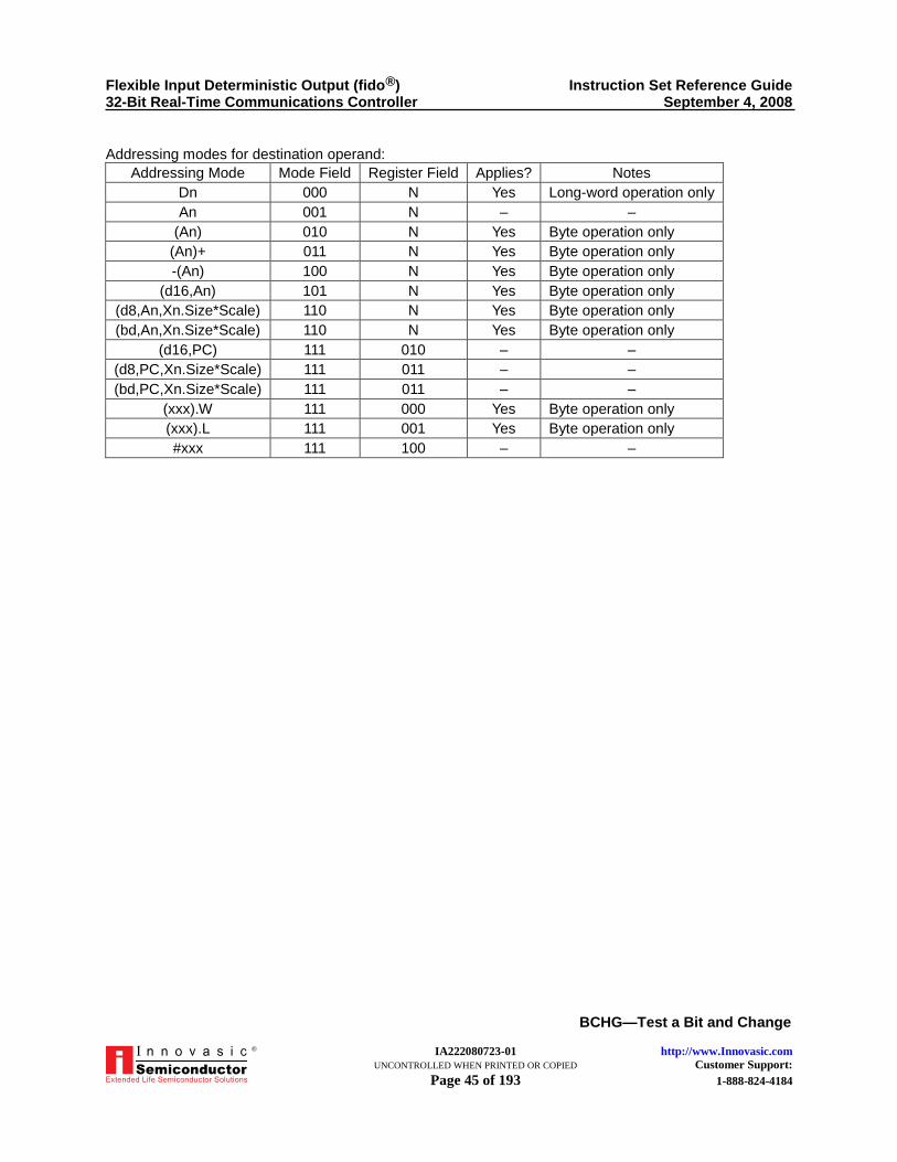
Addressing modes for destination operand:
Addressing Mode Mode Field Register Field Applies? Notes
Dn 000 N Yes Long-word operation only
An 001 N – –
(An) 010 N Yes Byte operation only
(An)+ 011 N Yes Byte operation only
-(An) 100 N Yes Byte operation only
(d16,An) 101 N Yes Byte operation only
(d8,An,Xn.Size*Scale) 110 N Yes Byte operation only
(bd,An,Xn.Size*Scale) 110 N Yes Byte operation only
(d16,PC) 111 010 – –
(d8,PC,Xn.Size*Scale) 111 011 – –
(bd,PC,Xn.Size*Scale) 111 011 – –
(xxx).W 111 000 Yes Byte operation only
(xxx).L 111 001 Yes Byte operation only
#xxx 111 100 – –
Instruction Format (Bit number dynamic, specified in register):
15 14 13 12 11 10 9 8 7 6 5 4 3 2 1 0
Op-Code Effective Address
0 0 0 0 Register 1 0 1 Mode Register
Where:
Register Field—Specifies the data register containing the bit number.
Effective-Address fields are as per Instruction Single Word Format and address mode
tables (see Table 2, Core Addressing Modes Summary) and always indicate a destination
operand.
Flexible Input Deterministic Output (fido®) Instruction Set Reference Guide 32-Bit Real-Time Communications Controller September 4, 2008
IA222080723-01 http://www.Innovasic.com UNCONTROLLED WHEN PRINTED OR COPIED Customer Support: Page 45 of 193 1-888-824-4184
BCHG—Test a Bit and Change
®
Addressing modes for destination operand:
Addressing Mode Mode Field Register Field Applies? Notes
Dn 000 N Yes Long-word operation only
An 001 N – –
(An) 010 N Yes Byte operation only
(An)+ 011 N Yes Byte operation only
-(An) 100 N Yes Byte operation only
(d16,An) 101 N Yes Byte operation only
(d8,An,Xn.Size*Scale) 110 N Yes Byte operation only
(bd,An,Xn.Size*Scale) 110 N Yes Byte operation only
(d16,PC) 111 010 – –
(d8,PC,Xn.Size*Scale) 111 011 – –
(bd,PC,Xn.Size*Scale) 111 011 – –
(xxx).W 111 000 Yes Byte operation only
(xxx).L 111 001 Yes Byte operation only
#xxx 111 100 – –

Flexible Input Deterministic Output (fido®) Instruction Set Reference Guide 32-Bit Real-Time Communications Controller September 4, 2008
IA222080723-01 http://www.Innovasic.com UNCONTROLLED WHEN PRINTED OR COPIED Customer Support: Page 46 of 193 1-888-824-4184
BCLR—Test a Bit and Clear
®
BCLR—Test a Bit and Clear
Assembler BCLR Dn, <ea>
Syntax: BCLR #<data>, <ea>
Operation:
Inverted bit number of destination → Z
0 → bit number of destination
Attributes: Size = byte (destination in memory), long (destination in data register)
Privileged: No
Notes:
When the destination is a data register any of the 32 bits can be specified by the modulo
32-bit number.
When the destination is in memory, the operation is a byte operation and the bit number
is modulo 8.
In all cases bit zero refers to the least significant bit.
The bit number can be specified in two ways:
– Immediate—The bit number is specified by the second instruction word (static).
– Register—The specified data register contains the bit number (dynamic).
Condition Codes:
X—Not affected
N—Not affected
Z—Set if bit tested is zero; cleared otherwise
V—Not affected
C—Not affected
Instruction Format (Bit number static, specified as immediate data):
.15 14 13 12 11 10 9 8 7 6 5 4 3 2 1 0
Op-Code Effective Address
0 0 0 0 1 0 0 0 0 1 Mode Register
0 0 0 0 0 0 0 0 Bit Number

Flexible Input Deterministic Output (fido®) Instruction Set Reference Guide 32-Bit Real-Time Communications Controller September 4, 2008
IA222080723-01 http://www.Innovasic.com UNCONTROLLED WHEN PRINTED OR COPIED Customer Support: Page 47 of 193 1-888-824-4184
BCLR—Test a Bit and Clear
®
Where:
Bit Number Field—Specifies the bit number.
Effective-Address fields are as per Instruction Single Word Format and address mode
tables (see Table 2, Core Addressing Modes Summary) and always indicate a destination
operand.
Addressing modes for destination operand:
Addressing Mode Mode Field Register Field Applies? Notes
Dn 000 N Yes Long-word operation only
An 001 N – –
(An) 010 N Yes Byte operation only
(An)+ 011 N Yes Byte operation only
-(An) 100 N Yes Byte operation only
(d16,An) 101 N Yes Byte operation only
(d8,An,Xn.Size*Scale) 110 N Yes Byte operation only
(bd,An,Xn.Size*Scale) 110 N Yes Byte operation only
(d16,PC) 111 010 – –
(d8,PC,Xn.Size*Scale) 111 011 – –
(bd,PC,Xn.Size*Scale) 111 011 – –
(xxx).W 111 000 Yes Byte operation only
(xxx).L 111 001 Yes Byte operation only
#xxx 111 100 – –
Instruction Format (Bit number dynamic, specified in register):
15 14 13 12 11 10 9 8 7 6 5 4 3 2 1 0
Op-Code Effective Address
1 1 0 1 Register 1 1 0 Mode Register
Where:
Register Field—specifies the data register containing the bit number.
Effective-Address fields are as per Instruction Single Word Format and address mode
tables (see Table 2, Core Addressing Modes Summary) and always indicate a destination
operand.

Flexible Input Deterministic Output (fido®) Instruction Set Reference Guide 32-Bit Real-Time Communications Controller September 4, 2008
IA222080723-01 http://www.Innovasic.com UNCONTROLLED WHEN PRINTED OR COPIED Customer Support: Page 48 of 193 1-888-824-4184
BCLR—Test a Bit and Clear
®
Addressing modes for destination operand:
Addressing Mode Mode Field Register Field Applies? Notes
Dn 000 N Yes Long-word operation only
An 001 N – –
(An) 010 N Yes Byte operation only
(An)+ 011 N Yes Byte operation only
-(An) 100 N Yes Byte operation only
(d16,An) 101 N Yes Byte operation only
(d8,An,Xn.Size*Scale) 110 N Yes Byte operation only
(bd,An,Xn.Size*Scale) 110 N Yes Byte operation only
(d16,PC) 111 010 – –
(d8,PC,Xn.Size*Scale) 111 011 – –
(bd,PC,Xn.Size*Scale) 111 011 – –
(xxx).W 111 000 Yes Byte operation only
(xxx).L 111 001 Yes Byte operation only
#xxx 111 100 – –

Flexible Input Deterministic Output (fido®) Instruction Set Reference Guide 32-Bit Real-Time Communications Controller September 4, 2008
IA222080723-01 http://www.Innovasic.com UNCONTROLLED WHEN PRINTED OR COPIED Customer Support: Page 49 of 193 1-888-824-4184
BGND—Enter Background Mode
®
BGND—Enter Background Mode
Assembler BGND
Syntax:
Operation: The CPU32 implementation of this instruction would stop normal execution and
enter Background Debug Mode (BDM). However, because BDM is not
implemented in the fido1100, this instruction will always generate a trace exception
instead.
Attributes: Size = unsized
Privileged: No
Notes: The trace exception vector is #12.
Condition Codes:
X—Not affected
N—Not affected
Z—Not affected
V—Not affected
C—Not affected
Instruction Format: 15 14 13 12 11 10 9 8 7 6 5 4 3 2 1 0
0 1 0 0 1 0 1 0 1 1 1 1 1 0 1 0

Flexible Input Deterministic Output (fido®) Instruction Set Reference Guide 32-Bit Real-Time Communications Controller September 4, 2008
IA222080723-01 http://www.Innovasic.com UNCONTROLLED WHEN PRINTED OR COPIED Customer Support: Page 50 of 193 1-888-824-4184
BKPT—Software Breakpoint
®
BKPT—Software Breakpoint
Assembler BKPT #<data>
Syntax:
Operation:
A BKPT bit in the Debug Control Register is used as follows:
– When clear (default)—the BKPT instruction performs as an NOP.
– When set—the BKPT instruction generates a breakpoint exception (vector #12),
routed to the current context. If required, a handler could re-route this to the master
context via the TRAPX instruction.
– The break point mode bit in the JTAG Debug Control Register Scan Chain also
affects the behavior of the BKPT instruction. If the bit is in its default position, then
the instruction generates a fault as described above. If the bit is in the other position
then the JTAG halt flag is set for the current context and no fault is generated.
Note: The fido1100 performs a different execution sequence than the CPU32
for this instruction. The value in <data> is ignored.
Attributes: Size = unsized
Privileged: No
Notes: Inserting a software breakpoint instruction into the code will require that it be running in
RAM or that it be compiled in.
Condition Codes:
X—Not affected
N—Not affected
Z—Not affected
V—Not affected
C—Not affected
Instruction Format: 15 14 13 12 11 10 9 8 7 6 5 4 3 2 1 0
0 1 0 0 1 0 0 0 0 1 0 0 1 X X X
Notes: Bits [2–0] are don’t cares since they are not used for this operation.
For don’t cares, any combination of bits are allowed.

Flexible Input Deterministic Output (fido®) Instruction Set Reference Guide 32-Bit Real-Time Communications Controller September 4, 2008
IA222080723-01 http://www.Innovasic.com UNCONTROLLED WHEN PRINTED OR COPIED Customer Support: Page 51 of 193 1-888-824-4184
BRA—Branch Always
®
BRA—Branch Always
Assembler BRA <label>
Syntax:
Operation: PC + displacement → PC
Privileged: No
Notes:
Program continues at PC + displacement.
After the instruction op-code is fetched, the PC contains the address of the BRA
instruction word plus two. The displacement is computed from this PC location.
The displacement is a two’s-complement integer representing the relative distance to the
new PC location.
If the 8-bit displacement is 0x00, the displacement is 16-bits, the word immediately
following the BRA op-code.
If the 8-bit displacement is 0xff, the displacement is 32-bits, the two words immediately
following the BRA op-code.
If the 8-bit displacement is not one of these two values then it is used as the displacement
and no more data follows the instruction op-code.
A branch instruction to the location immediately following automatically uses 16-bit
displacement because the 8-bit displacement field contains 0x00 (zero offset).
Condition Codes:
X—Not affected
N—Not affected
Z—Not affected
V—Not affected
C—Not affected
Instruction Format: 15 14 13 12 11 10 9 8 7 6 5 4 3 2 1 0
0 1 1 0 0 0 0 0 8-bit displacement
16-bit displacement (if 8-bit displacement of 0x00)
32-bit displacement (if 8-bit displacement is 0xff)

Flexible Input Deterministic Output (fido®) Instruction Set Reference Guide 32-Bit Real-Time Communications Controller September 4, 2008
IA222080723-01 http://www.Innovasic.com UNCONTROLLED WHEN PRINTED OR COPIED Customer Support: Page 52 of 193 1-888-824-4184
BSET—Test a Bit and Set
®
BSET—Test a Bit and Set
Assembler BSET Dn, <ea>
Syntax: BSET #<data>, <ea>
Operation:
Inverted bit number of destination → Z
1 → bit number of destination
Attributes: Size = byte (destination in memory), long (destination in data register)
Privileged: No
Notes:
When the destination is a data register any of the 32 bits can be specified by the modulo
32-bit number.
When the destination is in memory, the operation is a byte operation and the bit number
is modulo 8.
In all cases bit zero refers to the least significant bit.
The bit number can be specified in two ways:
– Immediate—The bit number is specified by the second instruction word (static)
– Register—The specified data register contains the bit number (dynamic)
Condition Codes:
X—Not affected
N—Not affected
Z—Set if bit tested is zero; cleared otherwise
V—Not affected
C—Not affected
Instruction Format (bit number static, specified as immediate data):
15 14 13 12 11 10 9 8 7 6 5 4 3 2 1 0
Op-Code Effective Address
0 0 0 0 1 0 0 0 1 1 Mode Register
0 0 0 0 0 0 0 0 Bit Number
Where:
Bit Number Field—Specifies the bit number.

Flexible Input Deterministic Output (fido®) Instruction Set Reference Guide 32-Bit Real-Time Communications Controller September 4, 2008
IA222080723-01 http://www.Innovasic.com UNCONTROLLED WHEN PRINTED OR COPIED Customer Support: Page 53 of 193 1-888-824-4184
BSET—Test a Bit and Set
®
Effective-Address fields are as per Instruction Single Word Format and address mode
tables (see Table 2, Core Addressing Modes Summary) and always indicate a destination
operand.
Addressing modes for destination operand:
Addressing Mode Mode Field Register Field Applies? Notes
Dn 000 N Yes Long-word operation only
An 001 N – –
(An) 010 N Yes Byte operation only
(An)+ 011 N Yes Byte operation only
-(An) 100 N Yes Byte operation only
(d16,An) 101 N Yes Byte operation only
(d8,An,Xn.Size*Scale) 110 N Yes Byte operation only
(bd,An,Xn.Size*Scale) 110 N Yes Byte operation only
(d16,PC) 111 010 – –
(d8,PC,Xn.Size*Scale) 111 011 – –
(bd,PC,Xn.Size*Scale) 111 011 – –
(xxx).W 111 000 Yes Byte operation only
(xxx).L 111 001 Yes Byte operation only
#xxx 111 100 – –
Instruction Format (Bit number dynamic, specified in register):
15 14 13 12 11 10 9 8 7 6 5 4 3 2 1 0
Op-Code Effective Address
0 0 0 0 Register 1 1 1 Mode Register
Where:
Register Field—specifies the data register containing the bit number.
Effective-Address fields are as per Instruction Single Word Format and address mode
tables (see Table 2, Core Addressing Modes Summary) and always indicate a destination
operand.

Flexible Input Deterministic Output (fido®) Instruction Set Reference Guide 32-Bit Real-Time Communications Controller September 4, 2008
IA222080723-01 http://www.Innovasic.com UNCONTROLLED WHEN PRINTED OR COPIED Customer Support: Page 54 of 193 1-888-824-4184
BSET—Test a Bit and Set
®
Addressing modes for destination operand:
Addressing Mode Mode Field Register Field Applies? Notes
Dn 000 N Yes Long-word operation only
An 001 N – –
(An) 010 N Yes Byte operation only
(An)+ 011 N Yes Byte operation only
-(An) 100 N Yes Byte operation only
(d16,An) 101 N Yes Byte operation only
(d8,An,Xn.Size*Scale) 110 N Yes Byte operation only
(bd,An,Xn.Size*Scale) 110 N Yes Byte operation only
(d16,PC) 111 010 – –
(d8,PC,Xn.Size*Scale) 111 011 – –
(bd,PC,Xn.Size*Scale) 111 011 – –
(xxx).W 111 000 Yes Byte operation only
(xxx).L 111 001 Yes Byte operation only
#xxx 111 100 – –
Flexible Input Deterministic Output (fido®) Instruction Set Reference Guide 32-Bit Real-Time Communications Controller September 4, 2008
IA222080723-01 http://www.Innovasic.com UNCONTROLLED WHEN PRINTED OR COPIED Customer Support: Page 55 of 193 1-888-824-4184
BSR—Branch to Subroutine
®
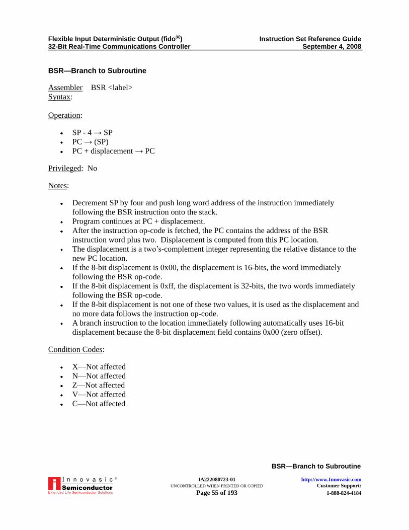
BSR—Branch to Subroutine
Assembler BSR <label>
Syntax:
Operation:
SP - 4 → SP
PC → (SP)
PC + displacement → PC
Privileged: No
Notes:
Decrement SP by four and push long word address of the instruction immediately
following the BSR instruction onto the stack.
Program continues at PC + displacement.
After the instruction op-code is fetched, the PC contains the address of the BSR
instruction word plus two. Displacement is computed from this PC location.
The displacement is a two’s-complement integer representing the relative distance to the
new PC location.
If the 8-bit displacement is 0x00, the displacement is 16-bits, the word immediately
following the BSR op-code.
If the 8-bit displacement is 0xff, the displacement is 32-bits, the two words immediately
following the BSR op-code.
If the 8-bit displacement is not one of these two values, it is used as the displacement and
no more data follows the instruction op-code.
A branch instruction to the location immediately following automatically uses 16-bit
displacement because the 8-bit displacement field contains 0x00 (zero offset).
Condition Codes:
X—Not affected
N—Not affected
Z—Not affected
V—Not affected
C—Not affected

Flexible Input Deterministic Output (fido®) Instruction Set Reference Guide 32-Bit Real-Time Communications Controller September 4, 2008
IA222080723-01 http://www.Innovasic.com UNCONTROLLED WHEN PRINTED OR COPIED Customer Support: Page 56 of 193 1-888-824-4184
BSR—Branch to Subroutine
®
Instruction Format: 15 14 13 12 11 10 9 8 7 6 5 4 3 2 1 0
0 1 1 0 0 0 0 1 8-bit displacement
16-bit displacement (if 8-bit displacement of 0x00)
32-bit displacement (if 8-bit displacement is 0xff)

Flexible Input Deterministic Output (fido®) Instruction Set Reference Guide 32-Bit Real-Time Communications Controller September 4, 2008
IA222080723-01 http://www.Innovasic.com UNCONTROLLED WHEN PRINTED OR COPIED Customer Support: Page 57 of 193 1-888-824-4184
BTST—Test a Bit
®
BTST—Test a Bit
Assembler BTST Dn, <ea>
Syntax: BTST #<data>, <ea>
Operation: Inverted bit number of destination → Z
Attributes: Size = byte (destination in memory), long (destination in data register)
Privileged: No
Notes:
When the destination is a data register any of the 32 bits can be specified by the modulo
32-bit number.
When the destination is in memory, the operation is a byte operation and the bit number
is modulo 8.
In all cases bit zero refers to the least significant bit.
The bit number can be specified in two ways:
– Immediate—The bit number is specified by the second instruction word (static)
– Register—The specified data register contains the bit number (dynamic)
Condition Codes:
X—Not affected
N—Not affected
Z—Set if bit tested is zero; cleared otherwise
V—Not affected
C—Not affected
Instruction Format (Bit number static, specified as immediate data):
15 14 13 12 11 10 9 8 7 6 5 4 3 2 1 0
Op-Code Effective Address
0 0 0 0 1 0 0 0 0 0 Mode Register
0 0 0 0 0 0 0 0 Bit Number
Where:
Bit Number Field—Specifies the bit number.
Effective-Address fields are as per Instruction Single Word Format and address mode
tables (see Table 2, Core Addressing Modes Summary) and always indicate a destination
operand.

Flexible Input Deterministic Output (fido®) Instruction Set Reference Guide 32-Bit Real-Time Communications Controller September 4, 2008
IA222080723-01 http://www.Innovasic.com UNCONTROLLED WHEN PRINTED OR COPIED Customer Support: Page 58 of 193 1-888-824-4184
BTST—Test a Bit
®
Addressing modes for destination operand:
Addressing Mode Mode Field Register Field Applies? Notes
Dn 000 N Yes Long-word operation only
An 001 N – –
(An) 010 N Yes Byte operation only
(An)+ 011 N Yes Byte operation only
-(An) 100 N Yes Byte operation only
(d16,An) 101 N Yes Byte operation only
(d8,An,Xn.Size*Scale) 110 N Yes Byte operation only
(bd,An,Xn.Size*Scale) 110 N Yes Byte operation only
(d16,PC) 111 010 Yes Byte operation only
(d8,PC,Xn.Size*Scale) 111 011 Yes Byte operation only
(bd,PC,Xn.Size*Scale) 111 011 Yes Byte operation only
(xxx).W 111 000 Yes Byte operation only
(xxx).L 111 001 Yes Byte operation only
#xxx 111 100 – –
Instruction Format (Bit number dynamic, specified in register):
15 14 13 12 11 10 9 8 7 6 5 4 3 2 1 0
Op-Code Effective Address
0 0 0 0 Register 1 0 0 Mode Register
Where:
Register Field—specifies the data register containing the bit number.
Effective-Address fields are as per Instruction Single Word Format and address mode
tables (see Table 2, Core Addressing Modes Summary) and always indicate a destination
operand.
Addressing modes for destination operand:
Addressing Mode Mode Field Register Field Applies? Notes
Dn 000 N Yes Long-word operation only
An 001 N – –
(An) 010 N Yes Byte operation only
(An)+ 011 N Yes Byte operation only
-(An) 100 N Yes Byte operation only
(d16,An) 101 N Yes Byte operation only
(d8,An,Xn.Size*Scale) 110 N Yes Byte operation only
(bd,An,Xn.Size*Scale) 110 N Yes Byte operation only
(d16,PC) 111 010 Yes Byte operation only
(d8,PC,Xn.Size*Scale) 111 011 Yes Byte operation only
(bd,PC,Xn.Size*Scale) 111 011 Yes Byte operation only
(xxx).W 111 000 Yes Byte operation only
(xxx).L 111 001 Yes Byte operation only
#xxx 111 100 Yes Byte operation only

Flexible Input Deterministic Output (fido®) Instruction Set Reference Guide 32-Bit Real-Time Communications Controller September 4, 2008
IA222080723-01 http://www.Innovasic.com UNCONTROLLED WHEN PRINTED OR COPIED Customer Support: Page 59 of 193 1-888-824-4184
CHK—Check Register Against Bounds
®
CHK—Check Register Against Bounds
Assembler CHK <ea>, Dn
Syntax:
Operation: If (Dn < 0) or (Dn > operand at effective address) then TRAP
Attributes: Size = word or long
Privileged: No
Notes:
Compares the value in the specified data register to zero and to the upper bound (effective
address operand).
The upper bound is a two’s-complement integer.
If the register value if less than zero or greater than the upper bound a CHK instruction
exception occurs, vector #6.
Condition Codes:
X—Not affected
N—Set if Dn < 0, cleared if Dn > operand at effective address, undefined otherwise
Z—Undefined
V—Undefined
C—Undefined
Instruction Format: 15 14 13 12 11 10 9 8 7 6 5 4 3 2 1 0
Op-Code Effective Address
0 1 0 0 Register Size 0 Mode Register
Where:
Register Field—Specifies the data register containing the value to be checked.
Size Field:
– 11—Word operation
– 10—Long operation
Effective-Address fields are as per Instruction Single Word Format and address mode
tables (see Table 2, Core Addressing Modes Summary) and always indicate the upper
bound operand.

Flexible Input Deterministic Output (fido®) Instruction Set Reference Guide 32-Bit Real-Time Communications Controller September 4, 2008
IA222080723-01 http://www.Innovasic.com UNCONTROLLED WHEN PRINTED OR COPIED Customer Support: Page 60 of 193 1-888-824-4184
CHK—Check Register Against Bounds
®
Addressing modes for upper bound operand:
Addressing Mode Mode Field Register Field Applies? Notes
Dn 000 N Yes Long-word operation
An 001 N – –
(An) 010 N Yes Byte operation only
(An)+ 011 N Yes Byte operation only
-(An) 100 N Yes Byte operation only
(d16,An) 101 N Yes Byte operation only
(d8,An,Xn.Size*Scale) 110 N Yes Byte operation only
(bd,An,Xn.Size*Scale) 110 N Yes Byte operation only
(d16,PC) 111 010 Yes Byte operation only
(d8,PC,Xn.Size*Scale) 111 011 Yes Byte operation only
(bd,PC,Xn.Size*Scale) 111 011 Yes Byte operation only
(xxx).W 111 000 Yes Byte operation only
(xxx).L 111 001 Yes Byte operation only
#xxx 111 100 – –

Flexible Input Deterministic Output (fido®) Instruction Set Reference Guide 32-Bit Real-Time Communications Controller September 4, 2008
IA222080723-01 http://www.Innovasic.com UNCONTROLLED WHEN PRINTED OR COPIED Customer Support: Page 61 of 193 1-888-824-4184
CHK2—Check Register Against Bounds
®
CHK2—Check Register Against Bounds
Assembler CHK2 <ea>, Rn
Syntax:
Operation: If (Rn < lower bound) or (Rn > upper bound) then TRAP
Attributes: Size = byte, word or long
Privileged: No
Notes:
Compares the value in the specified address or data register to each bound.
The effective address contains the bounds pair, the lower bound followed by the upper
bound.
For signed comparisons, the arithmetically smaller value should be the lower bound.
For unsigned comparisons, the logically smaller value should be the lower bound.
If Rn is a data register and the operation size is a byte or word, only the appropriate low
order part of Rn is checked.
If Rn is an address register and the operation size is a byte or word the bounds operands
are sign-extended to 32 bits and the full 32 bits of Rn are checked.
If the lower bound is equal to the upper bound, the valid range is a single value.
If the register value if less than lower bound or greater than the upper bound a CHK
instruction exception occurs, vector #6.
Condition Codes:
X—Not affected
N—Undefined
Z—Set if Rn is equal to either bound; cleared otherwise
V—Undefined
C—Set if Rn is out of bounds; cleared otherwise
Instruction Format:
15 14 13 12 11 10 9 8 7 6 5 4 3 2 1 0
Op-Code Effective Address
0 0 0 0 0 Size 0 1 1 Mode Register
D/A Register 1 0 0 0 0 0 0 0 0 0 0 0

Flexible Input Deterministic Output (fido®) Instruction Set Reference Guide 32-Bit Real-Time Communications Controller September 4, 2008
IA222080723-01 http://www.Innovasic.com UNCONTROLLED WHEN PRINTED OR COPIED Customer Support: Page 62 of 193 1-888-824-4184
CHK2—Check Register Against Bounds
®
Where:
Size Field:
– 00—byte operation
– 01—Word operation
– 10—Long operation
D/A Field—Specifies whether a data register or an address register is to be checked:
– 0—Data Register
– 1—Address Register
Register Field—Specifies the address or data register that contains the data to be checked.
Effective-Address fields are as per Instruction Single Word Format and address mode
tables (see Table 2, Core Addressing Modes Summary) and always indicate the location
of the bounds operand.
Addressing modes for upper bound operand:
Addressing Mode Mode Field Register Field Applies? Notes
Dn 000 N – –
An 001 N – –
(An) 010 N Yes –
(An)+ 011 N – –
-(An) 100 N – –
(d16,An) 101 N Yes –
(d8,An,Xn.Size*Scale) 110 N Yes –
(bd,An,Xn.Size*Scale) 110 N Yes –
(d16,PC) 111 010 Yes –
(d8,PC,Xn.Size*Scale) 111 011 Yes –
(bd,PC,Xn.Size*Scale) 111 011 Yes –
(xxx).W 111 000 Yes –
(xxx).L 111 001 Yes –
#xxx 111 100 – –

Flexible Input Deterministic Output (fido®) Instruction Set Reference Guide 32-Bit Real-Time Communications Controller September 4, 2008
IA222080723-01 http://www.Innovasic.com UNCONTROLLED WHEN PRINTED OR COPIED Customer Support: Page 63 of 193 1-888-824-4184
CLR—Clear an Operand
®
CLR—Clear an Operand
Assembler CLR <ea>
Syntax:
Operation: 0 → Destination
Attributes: Size = byte, word or long
Privileged: No
Condition Codes:
X—Not affected
N—Always Cleared
Z—Always Set
V—Always Cleared
C—Always Cleared
Instruction Format: 15 14 13 12 11 10 9 8 7 6 5 4 3 2 1 0
Op-Code Effective Address
0 1 0 0 0 0 1 0 Size Mode Register
Where:
Size Field:
– 00—Byte operation
– 01—Word operation
– 10—Long operation
Effective-Address fields are as per Instruction Single Word Format and address mode
tables (see Table 2, Core Addressing Modes Summary) and always indicate a destination
operand.

Flexible Input Deterministic Output (fido®) Instruction Set Reference Guide 32-Bit Real-Time Communications Controller September 4, 2008
IA222080723-01 http://www.Innovasic.com UNCONTROLLED WHEN PRINTED OR COPIED Customer Support: Page 64 of 193 1-888-824-4184
CLR—Clear an Operand
®
Addressing modes for destination operand:
Addressing Mode Mode Field Register Field Applies? Notes
Dn 000 N Yes –
An 001 N – –
(An) 010 N Yes –
(An)+ 011 N Yes –
-(An) 100 N Yes –
(d16,An) 101 N Yes –
(d8,An,Xn.Size*Scale) 110 N Yes –
(bd,An,Xn.Size*Scale) 110 N Yes –
(d16,PC) 111 010 – –
(d8,PC,Xn.Size*Scale) 111 011 – –
(bd,PC,Xn.Size*Scale) 111 011 – –
(xxx).W 111 000 Yes –
(xxx).L 111 001 Yes –
#xxx 111 100 – –

Flexible Input Deterministic Output (fido®) Instruction Set Reference Guide 32-Bit Real-Time Communications Controller September 4, 2008
IA222080723-01 http://www.Innovasic.com UNCONTROLLED WHEN PRINTED OR COPIED Customer Support: Page 65 of 193 1-888-824-4184
CMP—Compare
®
CMP—Compare
Assembler CMP <ea>, Dn
Syntax:
Operation: Destination − Source → Condition Code Register
Attributes: Size = byte, word or long
Privileged: No
Notes:
Destination is always a data register and is not changed by this operation. Byte and word-length source operands are sign-extended to 32 bits for comparison.
Condition Codes:
X—Not affected N—Set if result is negative; cleared otherwise Z—Set if result is zero; cleared otherwise V—Set if overflow occurs; cleared otherwise C—Set if borrow occurs; cleared otherwise
Instruction Format: 15 14 13 12 11 10 9 8 7 6 5 4 3 2 1 0
Op-Code Effective Address
1 0 1 1 Register Opmode Mode Register
Where:
Register Field—Specifies the destination data register. Opmode Field—Specifies the size of operation as follows:
Operation Byte Word Long
Dn - (EA) 100 001 010
Effective-Address fields are as per Instruction Single Word Format and address mode
tables (see Table 2, Core Addressing Modes Summary) and always indicate a source operand.

Flexible Input Deterministic Output (fido®) Instruction Set Reference Guide 32-Bit Real-Time Communications Controller September 4, 2008
IA222080723-01 http://www.Innovasic.com UNCONTROLLED WHEN PRINTED OR COPIED Customer Support: Page 66 of 193 1-888-824-4184
CMP—Compare
®
Addressing modes for source operand:
Addressing Mode Mode Field Register Field Applies? Notes
Dn 000 N Yes –
An 001 N Yes Word and long word only
(An) 010 N Yes –
(An)+ 011 N Yes –
-(An) 100 N Yes –
(d16,An) 101 N Yes –
(d8,An,Xn.Size*Scale) 110 N Yes –
(bd,An,Xn.Size*Scale) 110 N Yes –
(d16,PC) 111 010 Yes –
(d8,PC,Xn.Size*Scale) 111 011 Yes –
(bd,PC,Xn.Size*Scale) 111 011 Yes –
(xxx).W 111 000 Yes –
(xxx).L 111 001 Yes –
#xxx 111 100 Yes CMPI is used when the source is immediate data

Flexible Input Deterministic Output (fido®) Instruction Set Reference Guide 32-Bit Real-Time Communications Controller September 4, 2008
IA222080723-01 http://www.Innovasic.com UNCONTROLLED WHEN PRINTED OR COPIED Customer Support: Page 67 of 193 1-888-824-4184
CMP2—Compare Register Against Bounds
®
CMP2—Compare Register Against Bounds
Assembler CMP2 <ea>, Rn
Syntax:
Operation: Compare (Rn < lower bound) or (Rn > upper bound) then set condition code register.
Attributes: Size = byte, word or long
Privileged: No
Notes:
Compares the value in the specified address or data register to each bound.
The effective address contains the bounds pair, the lower bound followed by the upper
bound.
For signed comparisons, the arithmetically smaller value should be the lower bound.
For unsigned comparisons, the logically smaller value should be the lower bound.
If Rn is a data register and the operation size is a byte or word, only the appropriate low
order part of Rn is checked.
If Rn is an address register and the operation size is a byte or word the bounds operands
are sign-extended to 32 bits and the full 32 bits of Rn are checked.
If the lower bound is equal to the upper bound, the valid range is a single value.
The instruction is identical to the CHK2 instruction except the condition codes are set
rather than issuing an exception.
Condition Codes:
X—Not affected
N—Undefined
Z—Set if Rn is equal to either bound; cleared otherwise
V—Undefined
C—Set if Rn is out of bounds; cleared otherwise
Instruction Format: 15 14 13 12 11 10 9 8 7 6 5 4 3 2 1 0
Op-Code Effective Address
0 0 0 0 0 Size 0 1 1 Mode Register
D/A Register 0 0 0 0 0 0 0 0 0 0 0 0

Flexible Input Deterministic Output (fido®) Instruction Set Reference Guide 32-Bit Real-Time Communications Controller September 4, 2008
IA222080723-01 http://www.Innovasic.com UNCONTROLLED WHEN PRINTED OR COPIED Customer Support: Page 68 of 193 1-888-824-4184
CMP2—Compare Register Against Bounds
®
Where:
Size Field:
– 00—byte operation
– 01—Word operation
– 10—Long operation
D/A Field—Specifies whether a data register or an address register is to be checked:
– 0—Data Register
– 1—Address Register
Register Field—Specifies the address or data register that contains the data to be checked.
Effective-Address fields are as per Instruction Single Word Format and address mode
tables (see Table 2, Core Addressing Modes Summary) and always indicate the location
of the bounds operands.
Addressing modes for upper bound operand:
Addressing Mode Mode Field Register Field Applies? Notes
Dn 000 N – –
An 001 N – –
(An) 010 N Yes –
(An)+ 011 N – –
-(An) 100 N – –
(d16,An) 101 N Yes –
(d8,An,Xn.Size*Scale) 110 N Yes –
(bd,An,Xn.Size*Scale) 110 N Yes –
(d16,PC) 111 010 Yes –
(d8,PC,Xn.Size*Scale) 111 011 Yes –
(bd,PC,Xn.Size*Scale) 111 011 Yes –
(xxx).W 111 000 Yes –
(xxx).L 111 001 Yes –
#xxx 111 100 – –

Flexible Input Deterministic Output (fido®) Instruction Set Reference Guide 32-Bit Real-Time Communications Controller September 4, 2008
IA222080723-01 http://www.Innovasic.com UNCONTROLLED WHEN PRINTED OR COPIED Customer Support: Page 69 of 193 1-888-824-4184
CMPA—Compare Address
®
CMPA—Compare Address
Assembler CMPA <ea>, An
Syntax:
Operation: Destination − Source → Condition Code Register
Attributes: Size = word or long
Privileged: No
Notes:
Destination is always an address register and is not changed by this operation.
Word length source operands are sign-extended to 32 bits for comparison.
Condition Codes:
X—Not affected
N—Set if result is negative; cleared otherwise
Z—Set if result is zero; cleared otherwise
V—Set if overflow occurs; cleared otherwise
C—Set if borrow occurs; cleared otherwise
Instruction Format: 15 14 13 12 11 10 9 8 7 6 5 4 3 2 1 0
Op-Code Effective Address
1 0 1 1 Register Opmode Mode Register
Where:
Register Field—Specifies the destination address register.
Opmode Field—Specifies the size of operation as follows:
Operation Word Long
An - (EA) 011 111
Effective-Address fields are as per Instruction Single Word Format and address mode
tables (see Table 2, Core Addressing Modes Summary) and always indicate a source
operand.

Flexible Input Deterministic Output (fido®) Instruction Set Reference Guide 32-Bit Real-Time Communications Controller September 4, 2008
IA222080723-01 http://www.Innovasic.com UNCONTROLLED WHEN PRINTED OR COPIED Customer Support: Page 70 of 193 1-888-824-4184
CMPA—Compare Address
®
Addressing modes for source operand:
Addressing Mode Mode Field Register Field Applies? Notes
Dn 000 N Yes –
An 001 N Yes –
(An) 010 N Yes –
(An)+ 011 N Yes –
-(An) 100 N Yes –
(d16,An) 101 N Yes –
(d8,An,Xn.Size*Scale) 110 N Yes –
(bd,An,Xn.Size*Scale) 110 N Yes –
(d16,PC) 111 010 Yes –
(d8,PC,Xn.Size*Scale) 111 011 Yes –
(bd,PC,Xn.Size*Scale) 111 011 Yes –
(xxx).W 111 000 Yes –
(xxx).L 111 001 Yes –
#xxx 111 100 Yes –

Flexible Input Deterministic Output (fido®) Instruction Set Reference Guide 32-Bit Real-Time Communications Controller September 4, 2008
IA222080723-01 http://www.Innovasic.com UNCONTROLLED WHEN PRINTED OR COPIED Customer Support: Page 71 of 193 1-888-824-4184
CMPI—Compare Immediate
®
CMPI—Compare Immediate
Assembler CMPI #<data>, <ea>
Syntax:
Operation: Destination − Immediate Data → Condition Code Register
Attributes: Size = byte, word or long
Privileged: No
Notes:
Size of immediate data must match operand size
Destination location is not changed
Condition Codes:
X—Not affected
N—Set if result is negative; cleared otherwise
Z—Set if result is zero; cleared otherwise
V—Set if overflow occurs; cleared otherwise
C—Set if borrow occurs; cleared otherwise
Instruction Format: 15 14 13 12 11 10 9 8 7 6 5 4 3 2 1 0
0 0 0 0 1 1 0 0 Size Mode Register
Word Data (16-bits) Byte Data (8-bits)
Long data (32-bits)
Where:
Size Field (size of immediate data must match operand size):
– 00—Byte operation → data is low-order byte of immediate word
– 01—Word operation → data is the entire immediate word
– 10—Long operation → data is in the next two immediate words

Flexible Input Deterministic Output (fido®) Instruction Set Reference Guide 32-Bit Real-Time Communications Controller September 4, 2008
IA222080723-01 http://www.Innovasic.com UNCONTROLLED WHEN PRINTED OR COPIED Customer Support: Page 72 of 193 1-888-824-4184
CMPI—Compare Immediate
®
Addressing modes for destination operand:
Addressing Mode Mode Field Register Field Applies? Notes
Dn 000 N Yes –
An 001 N – –
(An) 010 N Yes –
(An)+ 011 N Yes –
-(An) 100 N Yes –
(d16,An) 101 N Yes –
(d8,An,Xn.Size*Scale) 110 N Yes –
(bd,An,Xn.Size*Scale) 110 N Yes –
(d16,PC) 111 010 Yes –
(d8,PC,Xn.Size*Scale) 111 011 Yes –
(bd,PC,Xn.Size*Scale) 111 011 Yes –
(xxx).W 111 000 Yes –
(xxx).L 111 001 Yes –
#xxx 111 100 – –

Flexible Input Deterministic Output (fido®) Instruction Set Reference Guide 32-Bit Real-Time Communications Controller September 4, 2008
IA222080723-01 http://www.Innovasic.com UNCONTROLLED WHEN PRINTED OR COPIED Customer Support: Page 73 of 193 1-888-824-4184
CMPM—Compare Memory
®
CMPM—Compare Memory
Assembler CMPM (Ay)+, (Ax)+
Syntax:
Operation: Destination − Source → Condition Code Register
Attributes: Size = byte, word or long
Privileged: No
Notes: Destination location is not changed
Condition Codes:
X—Not affected.
N—Set if result is negative; cleared otherwise
Z—Set if result is zero; cleared otherwise
V—Set if overflow occurs; cleared otherwise
C—Set if borrow occurs; cleared otherwise
Instruction Format: 15 14 13 12 11 10 9 8 7 6 5 4 3 2 1 0
1 0 1 1 Destination Register 1 Size 0 0 1 Source Register
Where:
Destination Register—Specifies an address register as the location of the destination
operand.
Size Field:
– 00—Byte operation
– 01—Word operation
– 10—Long operation
Source Register—Specifies an address register as the location of the source operand.
This instruction only uses only one addressing Mode, address register indirect with
postincrement: (An)+,(An)+ (both source and destination are pointed to by address registers).

Flexible Input Deterministic Output (fido®) Instruction Set Reference Guide 32-Bit Real-Time Communications Controller September 4, 2008
IA222080723-01 http://www.Innovasic.com UNCONTROLLED WHEN PRINTED OR COPIED Customer Support: Page 74 of 193 1-888-824-4184
DBCC—Test Condition, Decrement and Branch
®
DBCC—Test Condition, Decrement and Branch
Assembler DBCC Dn, <label>
Syntax:
Operation: If (condition false) then Dn − 1 → Dn, if (Dn ≠ -1) then PC + displacement → PC
Attributes: Size = word
Privileged: No
Notes:
Controls a loop of instructions, parameters are a condition code, a data register (counter),
and a displacement value.
First, the specified condition is tested, if true, no operation is performed and program
continues to next sequential program address.
If the condition is false (the condition is a termination test), the following operations are
performed:
– The low-order 16 bits of the counter data register are decremented by 1.
– If the result is -1, execution continues with the next instruction.
– If the result is not equal to 1, execution continues at the location specified by the
current value of the PC plus the sign-extended 16-bit displacement.
After the instruction op-code is fetched, the PC contains the address of the DBcc
instruction word plus 2. The displacement is computed from this PC location.
The displacement is a two’s-complement integer representing the relative distance to the
new PC location.
Condition Codes:
X—Not affected
N—Not affected
Z—Not affected
V—Not affected
C—Not affected
Instruction Format: 15 14 13 12 11 10 9 8 7 6 5 4 3 2 1 0
0 1 0 1 Condition 1 1 0 0 1 Register
16-Bit Displacement

Flexible Input Deterministic Output (fido®) Instruction Set Reference Guide 32-Bit Real-Time Communications Controller September 4, 2008
IA222080723-01 http://www.Innovasic.com UNCONTROLLED WHEN PRINTED OR COPIED Customer Support: Page 75 of 193 1-888-824-4184
DBCC—Test Condition, Decrement and Branch
®
Where:
Register—The data register to be used as the counter.
Condition—Specifies a conditional test according to the table below:
Condition Mnemonic Condition Code Description Details
CC DBCC 0100 Carry Clear ―!C‖
CS DBCS 0101 Carry Set ―C‖
EQ DBEQ 0111 Equal ―Z‖
F DBF 0001 Never Equal 0
GE DBGE 1100 Greater or Equal ―N&V;!N&!V‖
GT DBGT 1110 Greater Than ―N&V&!Z;!N&!V&!Z‖
HI DBHI 0010 High ―!C&!Z‖
LE DBLE 1111 Less or Equal ―Z;N&!V;!N&V‖
LS DBLS 0011 Low or Same ―!C;!Z‖
LT DBLT 1101 Less Than ―N&!V;!N&V‖
MI DBMI 1011 Minus ―N‖
NE DBNE 0110 Not Equal ―!Z‖
PL DBPL 1010 Plus ―!N‖
T DBT 0000 Always True 1
VC DBVC 1000 Overflow Clear ―!V‖
VS DBVS 1001 Overflow Set ―V‖

Flexible Input Deterministic Output (fido®) Instruction Set Reference Guide 32-Bit Real-Time Communications Controller September 4, 2008
IA222080723-01 http://www.Innovasic.com UNCONTROLLED WHEN PRINTED OR COPIED Customer Support: Page 76 of 193 1-888-824-4184
DIVS/DIVSL—Signed Divide
®
DIVS/DIVSL—Signed Divide
Assembler DIVS.W <ea>, Dn 32/16 → 16r:16q
Syntax: DIVS.L <ea>, Dq 32/32 → 32q
DIVS.L <ea>, Dr:Dq 64/32 → 32r:32q
DIVSL.L <ea>, Dr:Dq 32/32 → 32r:32q
Operation: Destination / Source → Destination
Attributes: Size = word or long
Privileged: No
Notes:
This instruction is interruptible. If the interrupt request is received before a certain point in the process, the division is aborted and the interrupt serviced. When the interrupt returns, the instruction is restarted.
Divides signed destination operand by signed source operand and stores result in destination operand location.
Four forms: – Word form divides a long word by a word. Result is quotient in lower 16 bits of
destination and remainder in upper 16 bits. Sign of remainder same as sign of dividend.
– First long form divides a long word by a long word. Result is long quotient. Remainder is discarded.
– Second long form divides a quad word (in any two data registers) by a long word. Result is a long-word quotient and a long-word remainder.
– Third long form divides a long word by a long word. Result is a long-word quotient and a long-word remainder.
Two special conditions may arise during the operation: – Division by zero causes a TRAP. – Overflow may be detected before instruction completion. If an overflow is detected,
the overflow condition code is set and the operands are unaffected. For word form, overflow occurs if quotient is larger than a 16-bit signed integer. For long forms, overflow occurs if quotient is larger than a 32-bit signed integer.
Condition Codes:
X—Not affected. N—Set if quotient is negative; cleared otherwise. Undefined if overflow or divide by
zero. Z—Set if quotient is zero; cleared otherwise. Undefined if overflow or divide by zero. V—Set if division overflow occurs, undefined if divide by zero; cleared otherwise. C—Always cleared.

Flexible Input Deterministic Output (fido®) Instruction Set Reference Guide 32-Bit Real-Time Communications Controller September 4, 2008
IA222080723-01 http://www.Innovasic.com UNCONTROLLED WHEN PRINTED OR COPIED Customer Support: Page 77 of 193 1-888-824-4184
DIVS/DIVSL—Signed Divide
®
Instruction Format (word form):
15 14 13 12 11 10 9 8 7 6 5 4 3 2 1 0
Op-Code Effective Address
1 0 0 0 Register 1 1 1 Mode Register
Where:
Register Field—Specifies any of the eight data registers. This field always specifies the
destination operand.
Effective-Address fields are as per Instruction Single Word Format and address mode
tables (see Table 2, Core Addressing Modes Summary) and always indicate a source
operand.
Addressing modes for source operand:
Addressing Mode Mode Field Register Field Applies? Notes
Dn 000 N Yes –
An 001 N – –
(An) 010 N Yes –
(An)+ 011 N Yes –
-(An) 100 N Yes –
(d16,An) 101 N Yes –
(d8,An,Xn.Size*Scale) 110 N Yes –
(bd,An,Xn.Size*Scale) 110 N Yes –
(d16,PC) 111 010 Yes –
(d8,PC,Xn.Size*Scale) 111 011 Yes –
(bd,PC,Xn.Size*Scale) 111 011 Yes –
(xxx).W 111 000 Yes –
(xxx).L 111 001 Yes –
#xxx 111 100 – –
Instruction Format (long form):
15 14 13 12 11 10 9 8 7 6 5 4 3 2 1 0
Op-Code Effective Address
0 1 0 0 1 1 0 0 0 1 Mode Register
0 Dq Register 1 Size 0 0 0 0 0 0 0 Dr Register
Where:
Dq Register Field—Specifies a data register for the destination operand. The low-order
32 bits of the dividend come from this register and the 32-bit quotient is loaded into this
register.

Flexible Input Deterministic Output (fido®) Instruction Set Reference Guide 32-Bit Real-Time Communications Controller September 4, 2008
IA222080723-01 http://www.Innovasic.com UNCONTROLLED WHEN PRINTED OR COPIED Customer Support: Page 78 of 193 1-888-824-4184
DIVS/DIVSL—Signed Divide
®
Size Field—Selects a 32-bit or 64-bit division operation:
– 0—32-bit dividend is in Dq register
– 1—64-bit dividend is in Dr:Dq registers
Dr Register Field:
– After the division, this register contains the 32-bit remainder. If Dr and Dq are the
same register, only the quotient is returned.
– If Size is 1, the Dr field also specifies the data register that contains the high-order 32
bits of the dividend.
Effective-Address fields are as per Instruction Single Word Format and address mode
tables (see Table 2, Core Addressing Modes Summary) and always indicate a source
operand.
Addressing modes for source operand:
Addressing Mode Mode Field Register Field Applies? Notes
Dn 000 N Yes –
An 001 N – –
(An) 010 N Yes –
(An)+ 011 N Yes –
-(An) 100 N Yes –
(d16,An) 101 N Yes –
(d8,An,Xn.Size*Scale) 110 N Yes –
(bd,An,Xn.Size*Scale) 110 N Yes –
(d16,PC) 111 010 Yes –
(d8,PC,Xn.Size*Scale) 111 011 Yes –
(bd,PC,Xn.Size*Scale) 111 011 Yes –
(xxx).W 111 000 Yes –
(xxx).L 111 001 Yes –
#xxx 111 100 Yes –

Flexible Input Deterministic Output (fido®) Instruction Set Reference Guide 32-Bit Real-Time Communications Controller September 4, 2008
IA222080723-01 http://www.Innovasic.com UNCONTROLLED WHEN PRINTED OR COPIED Customer Support: Page 79 of 193 1-888-824-4184
DIVU/DIVUL—Unsigned Divide
®
DIVU/DIVUL—Unsigned Divide
Assembler DIVU.W <ea>, Dn 32/16 → 16r:16q
Syntax: DIVU.L <ea>, Dq 32/32 → 32q
DIVU.L <ea>, Dr:Dq 64/32 → 32r:32q
DIVUL.L <ea>, Dr:Dq 32/32 → 32r:32q
Operation: Destination / Source → Destination
Attributes: Size = word or long
Privileged: No
Notes:
This instruction is interruptible. If the interrupt request is received before a certain point in the process, the division is aborted and the interrupt serviced. When the interrupt returns, the instruction is restarted.
Divides unsigned destination operand by unsigned source operand and stores result in destination operand location.
Four forms: 1. Word form divides a long word by a word. Result is quotient in lower 16 bits of
destination and remainder in upper 16 bits. 2. First long form divides a long word by a long word. Result is long quotient.
Remainder is discarded. 3. Second long form divides a quad word (in any two data registers) by a long word.
Result is a long-word quotient and a long-word remainder. 4. Third long form divides a long word by a long word. Result is a long word quotient
and a long word remainder. Two special conditions may arise during the operation:
1. Division by zero causes a TRAP. 2. Overflow may be detected before instruction completion. If an overflow is detected,
the overflow condition code is set and the operands are unaffected. For word form, overflow occurs if quotient is larger than a 16-bit signed integer. For long forms, overflow occurs if quotient is larger than a 32-bit signed integer.
Condition Codes:
X—Not affected. N—Set if quotient is negative; cleared otherwise. Undefined if overflow or divide by
zero. Z—Set if quotient is zero; cleared otherwise. Undefined if overflow or divide by zero. V—Set if division overflow occurs, undefined if divide by zero; cleared otherwise. C—Always cleared.

Flexible Input Deterministic Output (fido®) Instruction Set Reference Guide 32-Bit Real-Time Communications Controller September 4, 2008
IA222080723-01 http://www.Innovasic.com UNCONTROLLED WHEN PRINTED OR COPIED Customer Support: Page 80 of 193 1-888-824-4184
DIVU/DIVUL—Unsigned Divide
®
Instruction Format (word form):
15 14 13 12 11 10 9 8 7 6 5 4 3 2 1 0
Op-Code Effective Address
1 0 0 0 Register 0 1 1 Mode Register
Where:
Register Field—Specifies any of the eight data registers. This field always specifies the
destination operand.
Effective-Address fields are as per Instruction Single Word Format and address mode
tables (see Table 2, Core Addressing Modes Summary) and always indicate a source
operand.
Addressing modes for source operand:
Addressing Mode Mode Field Register Field Applies? Notes
Dn 000 N Yes –
An 001 N – –
(An) 010 N Yes –
(An)+ 011 N Yes –
-(An) 100 N Yes –
(d16,An) 101 N Yes –
(d8,An,Xn.Size*Scale) 110 N Yes –
(bd,An,Xn.Size*Scale) 110 N Yes –
(d16,PC) 111 010 Yes –
(d8,PC,Xn.Size*Scale) 111 011 Yes –
(bd,PC,Xn.Size*Scale) 111 011 Yes –
(xxx).W 111 000 Yes –
(xxx).L 111 001 Yes –
#xxx 111 100 Yes –
Instruction Format (long form):
15 14 13 12 11 10 9 8 7 6 5 4 3 2 1 0
Op-Code Effective Address
0 1 0 0 1 1 0 0 0 1 Mode Register
0 Dq Register 1 Size 0 0 0 0 0 0 0 Dr Register
Where:
Dq Register Field—Specifies a data register for the destination operand. The low-order
32 bits of the dividend come from this register, and the 32-bit quotient is loaded into this
register.

Flexible Input Deterministic Output (fido®) Instruction Set Reference Guide 32-Bit Real-Time Communications Controller September 4, 2008
IA222080723-01 http://www.Innovasic.com UNCONTROLLED WHEN PRINTED OR COPIED Customer Support: Page 81 of 193 1-888-824-4184
DIVU/DIVUL—Unsigned Divide
®
Size Field—Selects a 32-bit or 64-bit division operation:
– 0—32-bit dividend is in Dq register
– 1—64-bit dividend is in Dr:Dq registers
Dr Register Field:
– After the division, this register contains the 32-bit remainder. If Dr and Dq are the
same register, only the quotient is returned.
– If Size is 1, the Dr field also specifies the data register that contains the high-order 32
bits of the dividend.
Effective-Address fields are as per Instruction Single Word Format and address mode
tables (see Table 2, Core Addressing Modes Summary) and always indicate a source
operand.
Addressing modes for source operand:
Addressing Mode Mode Field Register Field Applies? Notes
Dn 000 N Yes –
An 001 N – –
(An) 010 N Yes –
(An)+ 011 N Yes –
-(An) 100 N Yes –
(d16,An) 101 N Yes –
(d8,An,Xn.Size*Scale) 110 N Yes –
(bd,An,Xn.Size*Scale) 110 N Yes –
(d16,PC) 111 010 Yes –
(d8,PC,Xn.Size*Scale) 111 011 Yes –
(bd,PC,Xn.Size*Scale) 111 011 Yes –
(xxx).W 111 000 Yes –
(xxx).L 111 001 Yes –
#xxx 111 100 Yes –

Flexible Input Deterministic Output (fido®) Instruction Set Reference Guide 32-Bit Real-Time Communications Controller September 4, 2008
IA222080723-01 http://www.Innovasic.com UNCONTROLLED WHEN PRINTED OR COPIED Customer Support: Page 82 of 193 1-888-824-4184
EOR—Exclusive OR
®
EOR—Exclusive OR
Assembler EOR Dn, <ea>
Syntax:
Operation: Source ^ Destination → Destination
Attributes: Size = byte, word or long
Privileged: No
Condition Codes:
X—Not affected
N—Set if most significant bit of result is set; cleared otherwise
Z—Set if result is zero; cleared otherwise
V—Always cleared
C—Always cleared
Instruction Format: 15 14 13 12 11 10 9 8 7 6 5 4 3 2 1 0
Op-Code Effective Address
1 0 1 1 Register Opmode Mode Register
Where:
Register Field—Specifies any one of the eight data registers.
Opmode Field—Specifies the size of the operation as follows:
Operation Byte Word Long
(EA) ^ (DN) → (EA) 000 001 010
Effective-Address fields are as per Instruction Single Word Format and address mode
tables (see Table 2, Core Addressing Modes Summary) and always indicate a destination
operand.

Flexible Input Deterministic Output (fido®) Instruction Set Reference Guide 32-Bit Real-Time Communications Controller September 4, 2008
IA222080723-01 http://www.Innovasic.com UNCONTROLLED WHEN PRINTED OR COPIED Customer Support: Page 83 of 193 1-888-824-4184
EOR—Exclusive OR
®
Addressing modes for destination operand:
Addressing Mode Mode Field Register Field Applies? Notes
Dn 000 N Yes –
An 001 N – –
(An) 010 N Yes –
(An)+ 011 N Yes –
-(An) 100 N Yes –
(d16,An) 101 N Yes –
(d8,An,Xn.Size*Scale) 110 N Yes –
(bd,An,Xn.Size*Scale) 110 N Yes –
(d16,PC) 111 010 – –
(d8,PC,Xn.Size*Scale) 111 011 – –
(bd,PC,Xn.Size*Scale) 111 011 – –
(xxx).W 111 000 Yes –
(xxx).L 111 001 Yes –
#xxx 111 100 – –

Flexible Input Deterministic Output (fido®) Instruction Set Reference Guide 32-Bit Real-Time Communications Controller September 4, 2008
IA222080723-01 http://www.Innovasic.com UNCONTROLLED WHEN PRINTED OR COPIED Customer Support: Page 84 of 193 1-888-824-4184
EORI—Exclusive OR Immediate
®
EORI—Exclusive OR Immediate
Assembler EORI #<data>, <ea>
Syntax:
Operation: Immediate Data ^ Destination → Destination
Attributes: Size = byte, word or long
Privileged: No
Condition Codes:
X—Not affected
N—Set if most significant bit of result is set; cleared otherwise
Z—Set if result is zero; cleared otherwise
V—Always cleared
C—Always cleared
Instruction Format: 15 14 13 12 11 10 9 8 7 6 5 4 3 2 1 0
0 0 0 0 1 0 1 0 Size Mode Register
Word Data (16-bits) Byte Data (8-bits)
Long data (32-bits)
Where:
Size Field (size of immediate data must match operand size):
– 00—Byte operation → data is low-order byte of immediate word
– 01—Word operation → data is the entire immediate word
– 10—Long operation → data is in the next two immediate words

Flexible Input Deterministic Output (fido®) Instruction Set Reference Guide 32-Bit Real-Time Communications Controller September 4, 2008
IA222080723-01 http://www.Innovasic.com UNCONTROLLED WHEN PRINTED OR COPIED Customer Support: Page 85 of 193 1-888-824-4184
EORI—Exclusive OR Immediate
®
Addressing modes for destination operand:
Addressing Mode Mode Field Register Field Applies? Notes
Dn 000 N Yes –
An 001 N – –
(An) 010 N Yes –
(An)+ 011 N Yes –
-(An) 100 N Yes –
(d16,An) 101 N Yes –
(d8,An,Xn.Size*Scale) 110 N Yes –
(bd,An,Xn.Size*Scale) 110 N Yes –
(d16,PC) 111 010 – –
(d8,PC,Xn.Size*Scale) 111 011 – –
(bd,PC,Xn.Size*Scale) 111 011 – –
(xxx).W 111 000 Yes –
(xxx).L 111 001 Yes –
#xxx 111 100 – –

Flexible Input Deterministic Output (fido®) Instruction Set Reference Guide 32-Bit Real-Time Communications Controller September 4, 2008
IA222080723-01 http://www.Innovasic.com UNCONTROLLED WHEN PRINTED OR COPIED Customer Support: Page 86 of 193 1-888-824-4184
EORI to CCR—Exclusive OR Immediate to Condition Code Register
®
EORI to CCR—Exclusive OR Immediate to Condition Code Register
Assembler EORI #<data>, CCR
Syntax:
Operation: Immediate Data Byte ^ CCR → CCR
Attributes: Size = byte
Privileged: No
Condition Codes:
X—Changed if [4] of immediate operand is one; unchanged otherwise
N—Changed if [3] of immediate operand is one; unchanged otherwise
Z—Changed if [2] of immediate operand is one; unchanged otherwise
V—Changed if [1] of immediate operand is one; unchanged otherwise
C—Changed if [0] of immediate operand is one; unchanged otherwise
Instruction Format: 15 14 13 12 11 10 9 8 7 6 5 4 3 2 1 0
0 0 0 0 1 0 1 0 0 0 1 1 1 1 0 0
0 0 0 0 0 0 0 0 Immediate Data Byte

Flexible Input Deterministic Output (fido®) Instruction Set Reference Guide 32-Bit Real-Time Communications Controller September 4, 2008
IA222080723-01 http://www.Innovasic.com UNCONTROLLED WHEN PRINTED OR COPIED Customer Support: Page 87 of 193 1-888-824-4184
EORI to SR—Exclusive OR Immediate to Status Register
®
EORI to SR—Exclusive OR Immediate to Status Register
Assembler EORI #<data>, SR
Syntax:
Operation: Immediate Data Word ^ SR → SR
Attributes: Size = word
Privileged: Yes
Condition Codes:
X—Changed if [4] of immediate operand is one; unchanged otherwise
N—Changed if [3] of immediate operand is one; unchanged otherwise
Z—Changed if [2] of immediate operand is one; unchanged otherwise
V—Changed if [1] of immediate operand is one; unchanged otherwise
C—Changed if [0] of immediate operand is one; unchanged otherwise
Instruction Format:
15 14 13 12 11 10 9 8 7 6 5 4 3 2 1 0
0 0 0 0 1 0 1 0 0 1 1 1 1 1 0 0
Immediate Data Word
Note: All implemented bits of the SR are affected.

Flexible Input Deterministic Output (fido®) Instruction Set Reference Guide 32-Bit Real-Time Communications Controller September 4, 2008
IA222080723-01 http://www.Innovasic.com UNCONTROLLED WHEN PRINTED OR COPIED Customer Support: Page 88 of 193 1-888-824-4184
EXG—Exchange Registers
®
EXG—Exchange Registers
Assembler EXG Dx, Dy
Syntax: EXG Ax, Ay
EXG Dx, Ay
EXG Ay, Dx
Operation: Rx ↔ Ry
Attributes: Size = long
Privileged: No
Notes:
Performs three types of exchanges:
1. Exchange data registers.
2. Exchange address registers.
3. Exchange a data register and an address register.
Condition Codes:
X—Not affected
N—Not affected
Z—Not affected
V—Not affected
C—Not affected
Instruction Format: 15 14 13 12 11 10 9 8 7 6 5 4 3 2 1 0
1 1 0 0 Register Rx 1 Opmode Register Ry
Where:
Register Rx Field—Specifies either a data or an address register depending on the mode.
If the exchange is between data and address registers, this field always specifies a data
register.
Opmode Field—specifies the type of exchange:
– 01000—Data registers
– 01001—Addresses registers
– 10001—Data and Address registers

Flexible Input Deterministic Output (fido®) Instruction Set Reference Guide 32-Bit Real-Time Communications Controller September 4, 2008
IA222080723-01 http://www.Innovasic.com UNCONTROLLED WHEN PRINTED OR COPIED Customer Support: Page 89 of 193 1-888-824-4184
EXG—Exchange Registers
®
Register Ry Field—Specifies either a data or an address register, depending on the mode.
If the exchange is between data and address registers, this field always specifies an
address register.

Flexible Input Deterministic Output (fido®) Instruction Set Reference Guide 32-Bit Real-Time Communications Controller September 4, 2008
IA222080723-01 http://www.Innovasic.com UNCONTROLLED WHEN PRINTED OR COPIED Customer Support: Page 90 of 193 1-888-824-4184
EXT/EXTB—Sign Extend
®
EXT/EXTB—Sign Extend
Assembler EXT.W Dn extend byte to word
Syntax: EXT.L Dn extend word to long word
EXTB.L Dn extend byte to long word
Operation: Destination sign-extended → Destination
Attributes: Size = word, long
Privileged: No
Notes: This instruction sign extends a byte in a data register to a word or a long word, or a word
in a data register to a long word, by replicating the sign bit to the left. If the operation
extends a byte to a word, Bit [7] of the designated data register is copied to Bits [15–8]
of that data register. If the operation extends a word to a long word, Bit [15] of the
designated data register is copied to Bits [31–16] of the data register. The EXTB form
copies Bit [7] of the designated register to Bits [31–8] of the data register.
Condition Codes:
X—Not affected
N—Set if the result is negative; cleared otherwise
Z—Set if result is zero; cleared otherwise
V—Always cleared
C—Always cleared
Instruction Format: 15 14 13 12 11 10 9 8 7 6 5 4 3 2 1 0
0 1 0 0 1 0 0 Opmode 0 0 0 Register
Where:
Opmode Field—Specifies the size of the sign extension operation:
– 010—Sign extend the low-order byte of data register to word
– 011—Sign extend the low-order word of data register to long
– 111—Sign extend the low-order byte of data register to long (EXTB)
Register Field—Specifies the data register to be sign-extended.

Flexible Input Deterministic Output (fido®) Instruction Set Reference Guide 32-Bit Real-Time Communications Controller September 4, 2008
IA222080723-01 http://www.Innovasic.com UNCONTROLLED WHEN PRINTED OR COPIED Customer Support: Page 91 of 193 1-888-824-4184
ILLEGAL—Take Illegal Instruction Trap
®
ILLEGAL—Take Illegal Instruction Trap
Assembler ILLEGAL
Syntax:
Operation:
SSP − 2 → SSP, Vector Offset → (SSP)
SSP − 4 → SSP, PC → (SSP)
SSP − 2 → SSP, SR → (SSP)
Illegal Instruction Vector Address → PC
Privileged: No
Notes:
Make internal copy of existing Status Register (SR) then modify the SR as follows:
– Set the S Bit establishing supervisor mode
– Clear the trace bits
Decrement Supervisor Stack Pointer (SSP) by two and push word containing stack frame
format and vector offset onto the supervisor’s stack. The normal four-word stack frame
format is used (stack frame format 0000).
Decrement Supervisor Stack Pointer (SSP) by four and push long word containing the
32-bit PC onto the supervisor’s stack.
Decrement Supervisor Stack Pointer (SSP) by two and push word containing status
register onto the supervisor’s stack.
Fetch a long word from memory pointed to by the Illegal Instruction Vector offset + the
VBR and place this in the PC.
Continue program execution at this location.
Condition Codes:
X—Not affected
N—Not affected
Z—Not affected
V—Not affected
C—Not affected
Instruction Format: 15 14 13 12 11 10 9 8 7 6 5 4 3 2 1 0
0 1 0 0 1 0 1 0 1 1 1 1 1 1 0 0

Flexible Input Deterministic Output (fido®) Instruction Set Reference Guide 32-Bit Real-Time Communications Controller September 4, 2008
IA222080723-01 http://www.Innovasic.com UNCONTROLLED WHEN PRINTED OR COPIED Customer Support: Page 92 of 193 1-888-824-4184
JMP—Jump
®
JMP—Jump
Assembler JMP <ea>
Syntax:
Operation: Destination Address → PC
Privileged: No
Notes: Program continues at the Destination Address specified by the instruction.
Condition Codes:
X—Not affected
N—Not affected
Z—Not affected
V—Not affected
C—Not affected
Instruction Format: 15 14 13 12 11 10 9 8 7 6 5 4 3 2 1 0
Op-Code Effective Address
0 1 0 0 1 1 1 0 1 1 Mode Register
Effective-Address fields are as per Instruction Single Word Format and address mode
tables (see Table 2, Core Addressing Modes Summary) and always indicate a destination
operand.
Addressing modes for destination operand:
Addressing Mode Mode Field Register Field Applies? Notes
Dn 000 N – –
An 001 N – –
(An) 010 N Yes –
(An)+ 011 N – –
-(An) 100 N – –
(d16,An) 101 N Yes –
(d8,An,Xn.Size*Scale) 110 N Yes –
(bd,An,Xn.Size*Scale) 110 N Yes –
(d16,PC) 111 010 Yes –
(d8,PC,Xn.Size*Scale) 111 011 Yes –
(bd,PC,Xn.Size*Scale) 111 011 Yes –
(xxx).W 111 000 Yes –
(xxx).L 111 001 Yes –
#xxx 111 100 – –

Flexible Input Deterministic Output (fido®) Instruction Set Reference Guide 32-Bit Real-Time Communications Controller September 4, 2008
IA222080723-01 http://www.Innovasic.com UNCONTROLLED WHEN PRINTED OR COPIED Customer Support: Page 93 of 193 1-888-824-4184
JSR—Jump to Subroutine
®
JSR—Jump to Subroutine
Assembler JSR <ea>
Syntax:
Operation:
SP − 4 → SP, PC → (SP)
Destination Address → PC
Privileged: No
Notes:
Decrement the SP by four and push the long-word address of the instruction immediately
following the JSR instruction onto the system stack.
Program continues at the Destination Address specified by the instruction.
Condition Codes:
X—Not affected
N—Not affected
Z—Not affected
V—Not affected
C—Not affected
Instruction Format: 15 14 13 12 11 10 9 8 7 6 5 4 3 2 1 0
Op-Code Effective Address
0 1 0 0 1 1 1 0 1 0 Mode Register
Where:
Effective-Address fields are as per Instruction Single Word Format and address mode
tables (see Table 2, Core Addressing Modes Summary) and always indicate a destination
operand.

Flexible Input Deterministic Output (fido®) Instruction Set Reference Guide 32-Bit Real-Time Communications Controller September 4, 2008
IA222080723-01 http://www.Innovasic.com UNCONTROLLED WHEN PRINTED OR COPIED Customer Support: Page 94 of 193 1-888-824-4184
JSR—Jump to Subroutine
®
Addressing modes for destination operand:
Addressing Mode Mode Field Register Field Applies? Notes
Dn 000 N – –
An 001 N – –
(An) 010 N Yes –
(An)+ 011 N – –
-(An) 100 N – –
(d16,An) 101 N Yes –
(d8,An,Xn.Size*Scale) 110 N Yes –
(bd,An,Xn.Size*Scale) 110 N Yes –
(d16,PC) 111 010 Yes –
(d8,PC,Xn.Size*Scale) 111 011 Yes –
(bd,PC,Xn.Size*Scale) 111 011 Yes –
(xxx).W 111 000 Yes –
(xxx).L 111 001 Yes –
#xxx 111 100 – –

Flexible Input Deterministic Output (fido®) Instruction Set Reference Guide 32-Bit Real-Time Communications Controller September 4, 2008
IA222080723-01 http://www.Innovasic.com UNCONTROLLED WHEN PRINTED OR COPIED Customer Support: Page 95 of 193 1-888-824-4184
LEA—Load Effective Address
®
LEA—Load Effective Address
Assembler LEA <ea>, An
Syntax:
Operation: EA → An
Privileged: No
Notes: Loads the effective address into the address register specified by the instruction.
Condition Codes:
X—Not affected
N—Not affected
Z—Not affected
V—Not affected
C—Not affected
Instruction Format: 15 14 13 12 11 10 9 8 7 6 5 4 3 2 1 0
Op-Code Effective Address
0 1 0 0 Register 1 1 1 Mode Register
Where:
Register Field—Specifies the Address register to be updated with the effective address.
Effective-Address fields are as per Instruction Single Word Format and address mode
tables (see Table 2, Core Addressing Modes Summary) and always indicate a source
operand.

Flexible Input Deterministic Output (fido®) Instruction Set Reference Guide 32-Bit Real-Time Communications Controller September 4, 2008
IA222080723-01 http://www.Innovasic.com UNCONTROLLED WHEN PRINTED OR COPIED Customer Support: Page 96 of 193 1-888-824-4184
LEA—Load Effective Address
®
Addressing modes for source operand:
Addressing Mode Mode Field Register Field Applies? Notes
Dn 000 N – –
An 001 N – –
(An) 010 N Yes –
(An)+ 011 N – –
-(An) 100 N – –
(d16,An) 101 N Yes –
(d8,An,Xn.Size*Scale) 110 N Yes –
(bd,An,Xn.Size*Scale) 110 N Yes –
(d16,PC) 111 010 Yes –
(d8,PC,Xn.Size*Scale) 111 011 Yes –
(bd,PC,Xn.Size*Scale) 111 011 Yes –
(xxx).W 111 000 Yes –
(xxx).L 111 001 Yes –
#xxx 111 100 – –

Flexible Input Deterministic Output (fido®) Instruction Set Reference Guide 32-Bit Real-Time Communications Controller September 4, 2008
IA222080723-01 http://www.Innovasic.com UNCONTROLLED WHEN PRINTED OR COPIED Customer Support: Page 97 of 193 1-888-824-4184
LINK—Link and Allocate
®
LINK—Link and Allocate
Assembler LINK An, #<displacement>
Syntax:
Operation:
SP − 4 → SP, An → (SP) SP → An, SP + displacement → SP
Attributes: Size = word or long
Privileged: No
Notes:
Decrement SP by four and push the 32-bit contents of the specified address register onto the stack.
Load the updated SP value into the specified Address Register. Finally, add the displacement value to the stack pointer.
– For word-size operation, the displacement is the sign-extended word following the instruction op-code.
– For long-size operation, the displacement is the long word following the instruction op-code.
The user should specify a negative displacement to allocate stack area.
Condition Codes:
X—Not affected N—Not affected Z—Not affected V—Not affected C—Not affected
Instruction Format: 15 14 13 12 11 10 9 8 7 6 5 4 3 2 1 0
0 1 0 0 1 1 1 0 0 1 0 1 0 Register
Word Displacement
15 14 13 12 11 10 9 8 7 6 5 4 3 2 1 0
0 1 0 0 1 0 0 0 0 0 0 1 1 Register
High-Order Displacement
Low-Order Displacement

Flexible Input Deterministic Output (fido®) Instruction Set Reference Guide 32-Bit Real-Time Communications Controller September 4, 2008
IA222080723-01 http://www.Innovasic.com UNCONTROLLED WHEN PRINTED OR COPIED Customer Support: Page 98 of 193 1-888-824-4184
LINK—Link and Allocate
®
Where:
Register Field—Specifies the address register for the link.
Displacement Field—Specifies the two’s-complement integer to be added to the stack
pointer.

Flexible Input Deterministic Output (fido®) Instruction Set Reference Guide 32-Bit Real-Time Communications Controller September 4, 2008
IA222080723-01 http://www.Innovasic.com UNCONTROLLED WHEN PRINTED OR COPIED Customer Support: Page 99 of 193 1-888-824-4184
LPSTOP—Low Power Stop
®
LPSTOP—Low Power Stop
Assembler LPSTOP #<data>
Syntax:
Operation:
Immediate data → SR
STOP (if executed by Master Context_0)
SLEEP (if executed by Context_1 to Context_4)
Attributes: Size = word
Privileged: Yes
Notes:
Immediate data is loaded into the entire status register.
The PC is advanced to point to the next instruction.
If executed by Master Context_0, then all processing is stopped, all internal clocks are
stopped, and the oscillator is HALT-ed.
If the instruction is executed by any other context, then that context is moved from
READY to NOT READY, but no change is made to clock operation (equivalent to
executing instruction SLEEP except that the status register is updated).
If the instruction was executed by Master Context_0, then processing resumes after an
external reset cycle.
Condition Codes:
X—Set according to the immediate operand
N—Set according to the immediate operand
Z—Set according to the immediate operand
V—Set according to the immediate operand
C—Set according to the immediate operand
Instruction Format: 15 14 13 12 11 10 9 8 7 6 5 4 3 2 1 0
1 1 1 1 1 0 0 0 0 0 0 0 0 0 0 0
0 0 0 0 0 0 0 1 1 1 0 0 0 0 0 0
Immediate Data

Flexible Input Deterministic Output (fido®) Instruction Set Reference Guide 32-Bit Real-Time Communications Controller September 4, 2008
IA222080723-01 http://www.Innovasic.com UNCONTROLLED WHEN PRINTED OR COPIED Customer Support: Page 100 of 193 1-888-824-4184
LSL/LSR—Logical Shift
®
LSL/LSR—Logical Shift
Assembler LSd Dx, Dy
Syntax: LSd #<data>, Dy
LSd <ea>
where d is direction, L or R
Operation: Destination shifted by count → Destination
Attributes: Size = byte, word or long
Privileged: No
Notes:
Performs logical shift operand left or right.
Shift either the contents of a data register or the contents of a memory location.
Carry and Extend Bit of CCR receives last bit shifted out of operand.
When shifting the contents of a data register, the shift count can be specified in two ways:
– Immediate—Shift count contained in instruction op-code.
– Register—Shift count is the value of a specified data register, modulo 64.
Contents of address registers cannot be shifted.
An operand in memory can be shifted by one bit only and operand size is restricted to a
word.
For Logical Shift Left (LSL):
– Operand is shifted left by the number of positions specified by the shift count.
– The high-order bit is shifted into both the X and Carry Bits.
– A zero is shifted into the low-order bit.
– The overflow bit is cleared by this operation.
For Logical Shift Right (LSR):
– Operand is shifted right by the number of positions specified by the shift count.
– The low-order bit is shifted into both the X and Carry Bits.
– A zero is shifted into the high-order bit.
– The overflow bit is cleared by this operation.
See Figure 1, Shift and Rotate Instructions, for a comparison of syntax, operand size, and
operation of ASL/ASR, LSL/LSR, ROL/ROR, ROXL/ROXR, and SWAP instructions.

Flexible Input Deterministic Output (fido®) Instruction Set Reference Guide 32-Bit Real-Time Communications Controller September 4, 2008
IA222080723-01 http://www.Innovasic.com UNCONTROLLED WHEN PRINTED OR COPIED Customer Support: Page 101 of 193 1-888-824-4184
LSL/LSR—Logical Shift
®
Condition Codes:
X—Set according to the last bit shifted out of the operand. Unaffected for a shift count
of zero.
N—Set if the result is negative; cleared otherwise.
Z—Set if result is zero; cleared otherwise.
V—Always cleared.
C—Set according to the last bit shifted out of the operand. Cleared for a shift count of
zero.
Instruction Format (register shifts):
15 14 13 12 11 10 9 8 7 6 5 4 3 2 1 0
1 1 1 0 Count/Register Dr Size I/R 0 1 Register
Where:
Count/Register Field:
– I/R = 0—This field specifies the shift count; ―1‖ through ―7‖ indicate shift one to
seven times and ―0‖ indicates shift eight times.
– I/R = 1—This field specifies the data register containing the shift count, modulo 64.
Dr Field—Specifies direction of the transfer:
– 0—Shift Right
– 1—Shift Left
Size Field:
– 00—Byte operation
– 01—Word operation
– 10—Long operation
I/R Field:
– 0—Shift count is defined by the instruction word
– 1—Shift count is defined by the specified data register, modulo 64
Register Field specifies the data register to shift.
Instruction Format (memory shifts):
15 14 13 12 11 10 9 8 7 6 5 4 3 2 1 0
Op-Code Effective Address
1 1 1 0 0 0 1 Dr 1 1 Mode Register

Flexible Input Deterministic Output (fido®) Instruction Set Reference Guide 32-Bit Real-Time Communications Controller September 4, 2008
IA222080723-01 http://www.Innovasic.com UNCONTROLLED WHEN PRINTED OR COPIED Customer Support: Page 102 of 193 1-888-824-4184
LSL/LSR—Logical Shift
®
Where:
Dr Field—Specifies direction of the transfer:
– 0—Shift Right
– 1—Shift Left
Effective-Address fields are as per Instruction Single Word Format and address mode
tables (see Table 2, Core Addressing Modes Summary) and always indicate the operand
to shift.

Flexible Input Deterministic Output (fido®) Instruction Set Reference Guide 32-Bit Real-Time Communications Controller September 4, 2008
IA222080723-01 http://www.Innovasic.com UNCONTROLLED WHEN PRINTED OR COPIED Customer Support: Page 103 of 193 1-888-824-4184
LSL/LSR—Logical Shift
®
Addressing modes for destination operand:
Addressing Mode Mode Field Register Field Applies? Notes
Dn 000 N – –
An 001 N – –
(An) 010 N Yes –
(An)+ 011 N Yes –
-(An) 100 N Yes –
(d16,An) 101 N Yes –
(d8,An,Xn.Size*Scale) 110 N Yes –
(bd,An,Xn.Size*Scale) 110 N Yes –
(d16,PC) 111 010 – –
(d8,PC,Xn.Size*Scale) 111 011 – –
(bd,PC,Xn.Size*Scale) 111 011 – –
(xxx).W 111 000 Yes –
(xxx).L 111 001 Yes –
#xxx 111 100 – –

Flexible Input Deterministic Output (fido®) Instruction Set Reference Guide 32-Bit Real-Time Communications Controller September 4, 2008
IA222080723-01 http://www.Innovasic.com UNCONTROLLED WHEN PRINTED OR COPIED Customer Support: Page 104 of 193 1-888-824-4184
MOVE—Move Data from Source to Destination
®
MOVE—Move Data from Source to Destination
Assembler MOVE <ea>, <ea>
Syntax:
Operation: Source → Destination
Attributes: Size = byte, word or long
Privileged: No
Condition Codes:
X—Not affected
N—Set if the result is negative; cleared otherwise
Z—Set if the result is zero; cleared otherwise
V—Always cleared
C—Always cleared
Instruction Format: 15 14 13 12 11 10 9 8 7 6 5 4 3 2 1 0
– – – Destination Effective Address
0 0 Size Register Mode Mode Register
Where:
Size Field:
– 01—Byte operation (not allowed for address register direct source Effective Address)
– 11—Word operation
– 10—Long operation
Note: The above differs from most other instructions for Size-Field
encoding.

Flexible Input Deterministic Output (fido®) Instruction Set Reference Guide 32-Bit Real-Time Communications Controller September 4, 2008
IA222080723-01 http://www.Innovasic.com UNCONTROLLED WHEN PRINTED OR COPIED Customer Support: Page 105 of 193 1-888-824-4184
MOVE—Move Data from Source to Destination
®
Addressing modes for destination operand:
Addressing Mode Mode Field Register Field Applies? Notes
Dn 000 N Yes –
An 001 N – –
(An) 010 N Yes –
(An)+ 011 N Yes –
-(An) 100 N Yes –
(d16,An) 101 N Yes –
(d8,An,Xn.Size*Scale) 110 N Yes –
(bd,An,Xn.Size*Scale) 110 N Yes –
(d16,PC) 111 010 – –
(d8,PC,Xn.Size*Scale) 111 011 – –
(bd,PC,Xn.Size*Scale) 111 011 – –
(xxx).W 111 000 Yes –
(xxx).L 111 001 Yes –
#xxx 111 100 – –
Effective-Address fields are as per Instruction Single Word Format and address mode
tables (see Table 6, Core Addressing Modes Summary) and always specifies the source
operand.
Addressing modes for source operand:
Addressing Mode Mode Field
Register Field Applies? Notes
Dn 000 N Yes –
An 001 N Yes Restricted to word and long word only
(An) 010 N Yes –
(An)+ 011 N Yes –
-(An) 100 N Yes –
(d16,An) 101 N Yes –
(d8,An,Xn.Size*Scale) 110 N Yes –
(bd,An,Xn.Size*Scale) 110 N Yes –
(d16,PC) 111 010 Yes –
(d8,PC,Xn.Size*Scale) 111 011 Yes –
(bd,PC,Xn.Size*Scale) 111 011 Yes –
(xxx).W 111 000 Yes –
(xxx).L 111 001 Yes –
#xxx 111 100 Yes –

Flexible Input Deterministic Output (fido®) Instruction Set Reference Guide 32-Bit Real-Time Communications Controller September 4, 2008
IA222080723-01 http://www.Innovasic.com UNCONTROLLED WHEN PRINTED OR COPIED Customer Support: Page 106 of 193 1-888-824-4184
MOVEA—Move Data from Source to Destination Address Register
®
MOVEA—Move Data from Source to Destination Address Register
Assembler MOVEA <ea>, An
Syntax:
Operation: Source → Destination
Attributes: Size = word or long
Privileged: No
Notes: Word-size operands are sign-extended to 32 bits and the result loaded into the specified
address register. All 32 bits of the address register are affected.
Condition Codes:
X—Not affected
N—Not affected
Z—Not affected
V—Not affected
C—Not affected
Instruction Format: 15 14 13 12 11 10 9 8 7 6 5 4 3 2 1 0
Op-Code Effective Address
0 0 Size Destination Register 0 0 1 Mode Register
Where:
Size Field:
– 11—Word operation
– 10—Long operation
Note: The above differs from most other instructions for Size-Field
encoding.
Destination-Register field specifies the destination address register.
Effective-Address fields are as per Instruction Single Word Format and address mode
tables (see Table 2, Core Addressing Modes Summary) and always indicate a source
operand.

Flexible Input Deterministic Output (fido®) Instruction Set Reference Guide 32-Bit Real-Time Communications Controller September 4, 2008
IA222080723-01 http://www.Innovasic.com UNCONTROLLED WHEN PRINTED OR COPIED Customer Support: Page 107 of 193 1-888-824-4184
MOVEA—Move Data from Source to Destination Address Register
®
Addressing modes for source operand: Addressing Mode Mode Field Register Field Applies? Notes
Dn 000 N Yes –
An 001 N Yes –
(An) 010 N Yes –
(An)+ 011 N Yes –
-(An) 100 N Yes –
(d16,An) 101 N Yes –
(d8,An,Xn.Size*Scale) 110 N Yes –
(bd,An,Xn.Size*Scale) 110 N Yes –
(d16,PC) 111 010 Yes –
(d8,PC,Xn.Size*Scale) 111 011 Yes –
(bd,PC,Xn.Size*Scale) 111 011 Yes –
(xxx).W 111 000 Yes –
(xxx).L 111 001 Yes –
#xxx 111 100 Yes –

Flexible Input Deterministic Output (fido®) Instruction Set Reference Guide 32-Bit Real-Time Communications Controller September 4, 2008
IA222080723-01 http://www.Innovasic.com UNCONTROLLED WHEN PRINTED OR COPIED Customer Support: Page 108 of 193 1-888-824-4184
MOVEC—Move Control Register
®
MOVEC—Move Control Register
Assembler MOVEC Rc, Rn
Syntax: MOVEC Rn, Rc
Operation:
Either move a control register to an address/data register or move an address/data register
to a control register:
– Rc → Rn
– Rn → Rc
Attributes: Size = long
Privileged: Yes
Condition Codes:
X—Not affected
N—Not affected
Z—Not affected
V—Not affected
C—Not affected
Notes:
MOVEC is always a 32-bit transfer even though the control register may be implemented
with fewer bits.
Unimplemented bits are read as zeros.
Instruction Format: 15 14 13 12 11 10 9 8 7 6 5 4 3 2 1 0
0 1 0 0 1 1 1 0 0 1 1 1 1 0 1 Dr
A/D Register Control Register
Where:
Dr Field—Specifies direction of the transfer:
– 0—Control register to general register
– 1—General register to control register
A/D Field—Specifies type of general register:
– 0—Data register
– 1—Address register

Flexible Input Deterministic Output (fido®) Instruction Set Reference Guide 32-Bit Real-Time Communications Controller September 4, 2008
IA222080723-01 http://www.Innovasic.com UNCONTROLLED WHEN PRINTED OR COPIED Customer Support: Page 109 of 193 1-888-824-4184
MOVEC—Move Control Register
®
Register Field—Specifies the register number.
Control Register Field—Specifies the control register:
– 0x000—Source Function Code (SFC).
– 0x001—Destination Function Code (DFC).
– 0x800—User Stack Pointer (USP).
– 0x801—Vector-Base Register (VBR).
– See Table 2, Core Addressing Modes Summary, for additional control codes. These
extended control codes are only valid when running as Master Context_0 (MC0).
– Any other code causes an illegal instruction exception.

Flexible Input Deterministic Output (fido®) Instruction Set Reference Guide 32-Bit Real-Time Communications Controller September 4, 2008
IA222080723-01 http://www.Innovasic.com UNCONTROLLED WHEN PRINTED OR COPIED Customer Support: Page 110 of 193 1-888-824-4184
MOVEM—Move Multiple Registers
®
MOVEM—Move Multiple Registers
Assembler MOVEM register list, <ea>
Syntax: MOVEM <ea>, register list
Operation:
Either move selected general registers to memory or move memory to selected general
registers:
– Registers − Destination
– Source − Registers
Attributes: Size = word or long
Privileged: No
Notes:
This instruction is interruptible. An interrupt request will cause the execution unit to
pause the register-move operation and service the interrupt. When the interrupt returns,
the instruction is continued from where it left off.
Register contents are moved to or from consecutive memory addresses.
A register is selected if the bit in the corresponding mask field location for that register is
set.
The instruction size determines whether 16 or 32 bits of each register is transferred. In
the case of a word transfer to either data or address registers, the word data is sign-
extended to 32 bits and the resulting long word is loaded into the register.
The addressing mode also affects the register transfer:
– If the specified addressing mode is one of the control modes:
o The registers are transferred starting at the specified address.
o The address is incremented by the operand length (2 or 4) following each transfer.
o The order of the registers is Data Register 0 to Data Register 7 then from Address
Register 0 to Address Register 7.
– If the specified addressing mode is the predecrement mode:
o Only a register-to-memory operation is allowed.
o The registers are stored starting at the specified address minus the operand length
(2 or 4).
o The address is decremented by the operand length (2 or 4) following each
transfer.
o The order of storing is Address Register 7 to Address Register 0 then from Data
Register 7 to Data Register 0.
o When the operation has completed, the decremented address register contains the
address of the last operand stored.

Flexible Input Deterministic Output (fido®) Instruction Set Reference Guide 32-Bit Real-Time Communications Controller September 4, 2008
IA222080723-01 http://www.Innovasic.com UNCONTROLLED WHEN PRINTED OR COPIED Customer Support: Page 111 of 193 1-888-824-4184
MOVEM—Move Multiple Registers
®
o If the addressing register is itself moved to memory, the value stored is the
decremented value.
– If the specified addressing mode is the postincrement mode:
o Only a memory-to-register operation is allowed.
o The registers are loaded starting at the specified address.
o The address is incremented by the operand length (2 or 4) following each transfer.
o The order of the registers is Data Register 0 to Data Register 7 then from Address
Register 0 to Address Register 7.
o When the operation has completed, the incremented address register contains the
address of the last operand loaded plus the operand length.
o If the address register itself is loaded from memory, the value loaded is the value
fetched plus the operand length.
Condition Codes:
X—Not affected
N—Not affected
Z—Not affected
V—Not affected
C—Not affected
Instruction Format: 15 14 13 12 11 10 9 8 7 6 5 4 3 2 1 0
Op-Code Effective Address
0 1 0 0 1 Dr 0 0 1 Size Mode Register
Register List Mask
Where:
Dr Field—Specifies direction of the transfer:
– 0—Registers to memory
– 1—Memory to registers
Size Field:
– 0—Word operation
– 1—Long operation
Register List Mask Field—Specifies the registers to be transferred:
– The low-order bit corresponds to the first register to be transferred; the high-order bit
corresponds to the last register to be transferred.
– For all allowable addressing modes except predecrement -(An) the mask
correspondence is:

Flexible Input Deterministic Output (fido®) Instruction Set Reference Guide 32-Bit Real-Time Communications Controller September 4, 2008
IA222080723-01 http://www.Innovasic.com UNCONTROLLED WHEN PRINTED OR COPIED Customer Support: Page 112 of 193 1-888-824-4184
MOVEM—Move Multiple Registers
®
15 14 13 12 11 10 9 8 7 6 5 4 3 2 1 0
A7 A6 A5 A4 A3 A2 A1 A0 D7 D6 D5 D4 D3 D2 D1 D0
– For the predecrement addressing mode -(An) the mask correspondence is reversed:
15 14 13 12 11 10 9 8 7 6 5 4 3 2 1 0
D0 D1 D2 D3 D4 D5 D6 D7 A0 A1 A2 A3 A4 A5 A6 A7
Effective-Address fields are as per Instruction Single Word Format and address mode
tables (see Table 7, Core Addressing Modes Summary) and always specifies the memory
location (source or destination). Different addressing modes are allowed depending on
the direction of the transfer.
Addressing modes for register-to-memory transfers: Addressing Mode Mode Field Register Field Applies? Notes
Dn 000 N – –
An 001 N – –
(An) 010 N Yes –
(An)+ 011 N – –
-(An) 100 N Yes –
(d16,An) 101 N Yes –
(d8,An,Xn.Size*Scale) 110 N Yes –
(bd,An,Xn.Size*Scale) 110 N Yes –
(d16,PC) 111 010 – –
(d8,PC,Xn.Size*Scale) 111 011 – –
(bd,PC,Xn.Size*Scale) 111 011 – –
(xxx).W 111 000 Yes –
(xxx).L 111 001 Yes –
#xxx 111 100 – –

Flexible Input Deterministic Output (fido®) Instruction Set Reference Guide 32-Bit Real-Time Communications Controller September 4, 2008
IA222080723-01 http://www.Innovasic.com UNCONTROLLED WHEN PRINTED OR COPIED Customer Support: Page 113 of 193 1-888-824-4184
MOVEM—Move Multiple Registers
®
Addressing modes for memory-to-register transfers:
Addressing Mode Mode Field Register Field Applies? Notes
Dn 000 N – –
An 001 N – –
(An) 010 N Yes –
(An)+ 011 N – –
-(An) 100 N Yes –
(d16,An) 101 N Yes –
(d8,An,Xn.Size*Scale) 110 N Yes –
(bd,An,Xn.Size*Scale) 110 N Yes –
(d16,PC) 111 010 – –
(d8,PC,Xn.Size*Scale) 111 011 – –
(bd,PC,Xn.Size*Scale) 111 011 – –
(xxx).W 111 000 Yes –
(xxx).L 111 001 Yes –
#xxx 111 100 – –

Flexible Input Deterministic Output (fido®) Instruction Set Reference Guide 32-Bit Real-Time Communications Controller September 4, 2008
IA222080723-01 http://www.Innovasic.com UNCONTROLLED WHEN PRINTED OR COPIED Customer Support: Page 114 of 193 1-888-824-4184
MOVEP—Move Peripheral Data
®
MOVEP—Move Peripheral Data
Assembler MOVEP Dx, (d, Ay)
Syntax: MOVEP (d, Ay), Dx
Operation:
Either move data from a data register to memory or move data from memory to a data register: – Dn → Destination – Source → Dn
Attributes: Size = word or long
Privileged: No
Notes:
This instruction is designed 8-bit peripherals on a 16-bit data bus – Moves data between a data register and alternate bytes within the address space,
starting at the address specified and incrementing by two. – The high-order byte of the data register is transferred first and the low-order byte
transferred last. – If the starting address is even, all data is transferred using the high-order half of the
16-bit data bus. – If the starting address is odd, all data is transferred using the low-order half of the
16-bit data bus. – The instruction also accesses alternate bytes on an 8-bit or 32-bit bus.
This instruction only uses one addressing mode: – Address register indirect plus 16-bit displacement (d16,An)
Condition Codes:
X—Not affected N—Not affected Z—Not affected V—Not affected C—Not affected
Instruction Format:
15 14 13 12 11 10 9 8 7 6 5 4 3 2 1 0
0 0 0 0 Data Register Opmode 0 0 1 Address Register
16-Bit Displacement

Flexible Input Deterministic Output (fido®) Instruction Set Reference Guide 32-Bit Real-Time Communications Controller September 4, 2008
IA222080723-01 http://www.Innovasic.com UNCONTROLLED WHEN PRINTED OR COPIED Customer Support: Page 115 of 193 1-888-824-4184
MOVEP—Move Peripheral Data
®
Where:
Data Register Field—Specifies the data register for the instruction. Opmode Field—Specifies the direction and size of the operation:
– 100—Transfer word from memory to register – 101—Transfer long from memory to register – 110—Transfer word from register to memory – 111—Transfer long from register to memory
Address Register Field—Specifies the address register used in the address register
indirect plus 16-bit displacement addressing mode.
Displacement Field—Specifies the 16-bit displacement used in the operand address.

Flexible Input Deterministic Output (fido®) Instruction Set Reference Guide 32-Bit Real-Time Communications Controller September 4, 2008
IA222080723-01 http://www.Innovasic.com UNCONTROLLED WHEN PRINTED OR COPIED Customer Support: Page 116 of 193 1-888-824-4184
MOVEQ—Move Quick
®
MOVEQ—Move Quick
Assembler MOVEQ #<data>, Dn
Syntax:
Operation: Immediate Data → Destination
Attributes: Size = long
Privileged: No
Notes: Moves a byte of data to a 32-bit data register. The data byte is sign-extended to 32 bits
and result loaded into the specified data register. All 32 bits of the data register are
affected.
Condition Codes:
X—Not affected
N—Set if result is negative; cleared otherwise
Z—Set if result is zero; cleared otherwise
V—Always cleared
C—Always cleared
Instruction Format: 15 14 13 12 11 10 9 8 7 6 5 4 3 2 1 0
0 1 1 1 Register 0 Data
Where:
Register Field—Specifies the destination data register.
Data Field—Provides the immediate data byte.

Flexible Input Deterministic Output (fido®) Instruction Set Reference Guide 32-Bit Real-Time Communications Controller September 4, 2008
IA222080723-01 http://www.Innovasic.com UNCONTROLLED WHEN PRINTED OR COPIED Customer Support: Page 117 of 193 1-888-824-4184
MOVES—Move Address Space
®
MOVES—Move Address Space
Assembler MOVES Rn, <ea>
Syntax: MOVES <ea>, Rn
Operation:
This instruction has two forms:
– Move data from a specified general purpose register to memory:
o Rn → (EA)
– Move data from memory to the specified general purpose register:
o (EA) → Rn
Attributes: Size = byte, word or long
Privileged: Yes
Notes:
The fido1100 does not implement separate address spaces, therefore this instruction is
equivalent to the MOVE instruction.
If the destination is a data register, the operand will replace the corresponding low-order
bits of the destination data register. If the destination is an address register, the source
operand is sign-extended to 32 bits and result loaded into the specified address register.
All 32 bits of the address register are affected.
If the instruction format specifies the same address register for both source and
destination, the value stored is undefined. For example the instruction MOVES.x
A0,(A0)+ will try to store the A0 register at the memory location where the A0 register
points, then increment it. The value stored may be the original or the incremented value
of the A0 register.
Condition Codes:
X—Not affected
N—Not affected
Z—Not affected
V—Not affected
C—Not affected

Flexible Input Deterministic Output (fido®) Instruction Set Reference Guide 32-Bit Real-Time Communications Controller September 4, 2008
IA222080723-01 http://www.Innovasic.com UNCONTROLLED WHEN PRINTED OR COPIED Customer Support: Page 118 of 193 1-888-824-4184
MOVES—Move Address Space
®
Instruction Format: 15 14 13 12 11 10 9 8 7 6 5 4 3 2 1 0
Op-Code Effective Address
0 0 0 0 1 1 1 0 Size Mode Register
A/D Register Dr 0 0 0 0 0 0 0 0 0 0 0
Where:
Size Field:
– 00—Byte operation
– 01—Word operation
– 10—Long operation
A/D Field—Specifies the type of general register.
– 0—Data register
– 1—Address register
Register Field—Specifies the register number.
Dr Field—Specifies direction of transfer:
– 0—From (EA) to general register
– 1—From general register to (EA)
Effective-Address fields are as per Instruction Single Word Format and address mode
tables (see Table 8, Core Addressing Modes Summary).
Addressing modes for source or destination operands:
Addressing Mode Mode Field Register Field Applies? Notes
Dn 000 N – –
An 001 N – –
(An) 010 N Yes –
(An)+ 011 N Yes –
-(An) 100 N Yes –
(d16,An) 101 N Yes –
(d8,An,Xn.Size*Scale) 110 N Yes –
(bd,An,Xn.Size*Scale) 110 N Yes –
(d16,PC) 111 010 – –
(d8,PC,Xn.Size*Scale) 111 011 – –
(bd,PC,Xn.Size*Scale) 111 011 – –
(xxx).W 111 000 Yes –
(xxx).L 111 001 Yes –
#xxx 111 100 – –

Flexible Input Deterministic Output (fido®) Instruction Set Reference Guide 32-Bit Real-Time Communications Controller September 4, 2008
IA222080723-01 http://www.Innovasic.com UNCONTROLLED WHEN PRINTED OR COPIED Customer Support: Page 119 of 193 1-888-824-4184
MOVE from CCR —Move Data from the Condition Code Register
®
MOVE from CCR —Move Data from the Condition Code Register
Assembler MOVE CCR, <ea>
Syntax:
Operation: CCR → Destination
Attributes: Size = word
Privileged: No
Notes: Moves the condition code register bits (zero extended to word size) to the destination
location. Unimplemented bits are read as zeros.
Condition Codes:
X—Not affected
N—Not affected
Z—Not affected
V—Not affected
C—Not affected
Instruction Format: 15 14 13 12 11 10 9 8 7 6 5 4 3 2 1 0
Op-Code Effective Address
0 1 0 0 0 0 1 0 1 1 Mode Register
Where:
Effective-Address fields are as per Instruction Single Word Format and address mode
tables (see Table 2, Core Addressing Modes Summary) and always indicate the
destination operand.

Flexible Input Deterministic Output (fido®) Instruction Set Reference Guide 32-Bit Real-Time Communications Controller September 4, 2008
IA222080723-01 http://www.Innovasic.com UNCONTROLLED WHEN PRINTED OR COPIED Customer Support: Page 120 of 193 1-888-824-4184
MOVE from CCR —Move Data from the Condition Code Register
®
Addressing modes for destination operand: Addressing Mode Mode Field Register Field Applies? Notes
Dn 000 N Yes –
An 001 N – –
(An) 010 N Yes –
(An)+ 011 N Yes –
-(An) 100 N Yes –
(d16,An) 101 N Yes –
(d8,An,Xn.Size*Scale) 110 N Yes –
(bd,An,Xn.Size*Scale) 110 N Yes –
(d16,PC) 111 010 – –
(d8,PC,Xn.Size*Scale) 111 011 – –
(bd,PC,Xn.Size*Scale) 111 011 – –
(xxx).W 111 000 Yes –
(xxx).L 111 001 Yes –
#xxx 111 100 – –

Flexible Input Deterministic Output (fido®) Instruction Set Reference Guide 32-Bit Real-Time Communications Controller September 4, 2008
IA222080723-01 http://www.Innovasic.com UNCONTROLLED WHEN PRINTED OR COPIED Customer Support: Page 121 of 193 1-888-824-4184
MOVE to CCR —Move Data to the Condition Code Register
®
MOVE to CCR —Move Data to the Condition Code Register
Assembler MOVE <ea>, CCR
Syntax:
Operation: Source → CCR
Attributes: Size = word
Privileged: No
Notes:
Moves the low-order byte of the source operand to the condition code register.
The upper byte of the source operand is ignored.
The upper byte of the status register is not altered.
Condition Codes:
X—set to the value of [4] of source operand
N—set to the value of [3] of source operand
Z—set to the value of [2] of source operand
V—set to the value of [1] of source operand
C—set to the value of [0] of source operand
Instruction Format: 15 14 13 12 11 10 9 8 7 6 5 4 3 2 1 0
Op-Code Effective Address
0 1 0 0 0 1 0 0 1 1 Mode Register
Where:
Effective-Address fields are as per Instruction Single Word Format and address mode
tables (see Table 2, Core Addressing Modes Summary) and always indicate the source
operand.

Flexible Input Deterministic Output (fido®) Instruction Set Reference Guide 32-Bit Real-Time Communications Controller September 4, 2008
IA222080723-01 http://www.Innovasic.com UNCONTROLLED WHEN PRINTED OR COPIED Customer Support: Page 122 of 193 1-888-824-4184
MOVE to CCR —Move Data to the Condition Code Register
®
Addressing modes for source operand:
Addressing Mode Mode Field Register Field Applies? Notes
Dn 000 N Yes –
An 001 N – –
(An) 010 N Yes –
(An)+ 011 N Yes –
-(An) 100 N Yes –
(d16,An) 101 N Yes –
(d8,An,Xn.Size*Scale) 110 N Yes –
(bd,An,Xn.Size*Scale) 110 N Yes –
(d16,PC) 111 010 Yes –
(d8,PC,Xn.Size*Scale) 111 011 Yes –
(bd,PC,Xn.Size*Scale) 111 011 Yes –
(xxx).W 111 000 Yes –
(xxx).L 111 001 Yes –
#xxx 111 100 Yes –

Flexible Input Deterministic Output (fido®) Instruction Set Reference Guide 32-Bit Real-Time Communications Controller September 4, 2008
IA222080723-01 http://www.Innovasic.com UNCONTROLLED WHEN PRINTED OR COPIED Customer Support: Page 123 of 193 1-888-824-4184
MOVE from SR —Move Data from the Status Register
®
MOVE from SR —Move Data from the Status Register
Assembler MOVE SR, <ea>
Syntax:
Operation: SR → Destination
Attributes: Size = word
Privileged: Yes
Notes: Moves the data in the status register to the destination location. The destination must be
of word length. Unimplemented bits are read as zeros.
Condition Codes:
X—Not affected
N—Not affected
Z—Not affected
V—Not affected
C—Not affected
Instruction Format: 15 14 13 12 11 10 9 8 7 6 5 4 3 2 1 0
Op-Code Effective Address
0 1 0 0 0 0 0 0 1 1 Mode Register
Where:
Effective-Address fields are as per Instruction Single Word Format and address mode
tables (see Table 2, Core Addressing Modes Summary) and always indicate the
destination operand.

Flexible Input Deterministic Output (fido®) Instruction Set Reference Guide 32-Bit Real-Time Communications Controller September 4, 2008
IA222080723-01 http://www.Innovasic.com UNCONTROLLED WHEN PRINTED OR COPIED Customer Support: Page 124 of 193 1-888-824-4184
MOVE from SR —Move Data from the Status Register
®
Addressing modes for destination operand: Addressing Mode Mode Field Register Field Applies? Notes
Dn 000 N Yes –
An 001 N – –
(An) 010 N Yes –
(An)+ 011 N Yes –
-(An) 100 N Yes –
(d16,An) 101 N Yes –
(d8,An,Xn.Size*Scale) 110 N Yes –
(bd,An,Xn.Size*Scale) 110 N Yes –
(d16,PC) 111 010 – –
(d8,PC,Xn.Size*Scale) 111 011 – –
(bd,PC,Xn.Size*Scale) 111 011 – –
(xxx).W 111 000 Yes –
(xxx).L 111 001 Yes –
#xxx 111 100 – –

Flexible Input Deterministic Output (fido®) Instruction Set Reference Guide 32-Bit Real-Time Communications Controller September 4, 2008
IA222080723-01 http://www.Innovasic.com UNCONTROLLED WHEN PRINTED OR COPIED Customer Support: Page 125 of 193 1-888-824-4184
MOVE USP—Move User Stack Pointer
®
MOVE USP—Move User Stack Pointer
Assembler MOVE USP, An
Syntax: MOVE An, USP
Operation:
Either move the user stack pointer to an address register or move the address register to
the user stack pointer:
– USP → An
– An → USP
Attributes: Size = long
Privileged: Yes
Condition Codes:
X—Not affected
N—Not affected
Z—Not affected
V—Not affected
C—Not affected
Instruction Format: 15 14 13 12 11 10 9 8 7 6 5 4 3 2 1 0
0 1 0 0 1 1 1 0 0 1 1 0 Dr Register
Where:
Dr Field—Specifies direction of the transfer:
– 0—Transfer address register to the USP
– 1—Transfer the USP to the address register
Register Field—Specifies the address register to use for the operation.

Flexible Input Deterministic Output (fido®) Instruction Set Reference Guide 32-Bit Real-Time Communications Controller September 4, 2008
IA222080723-01 http://www.Innovasic.com UNCONTROLLED WHEN PRINTED OR COPIED Customer Support: Page 126 of 193 1-888-824-4184
MULS—Signed Multiply
®
MULS—Signed Multiply
Assembler MULS.W <ea>, Dn 16x16 → 32
Syntax: MULS.L <ea>, Dl 32x32 → 32
MULS.L <ea>, Dh:Dl 32x32 → 64
Operation: Source * Destination → Destination
Attributes: Size = word or long
Privileged: No
Notes:
Multiplies two signed operands yielding a signed result.
Two forms:
1. The word form multiplies a word multiplicand by a word multiplier. The result is a
long-word product stored in a data register. All 32 bits are affected. When a register
provides a source operand only the lower 16 bits are used in the operation; the upper
16 bits are ignored.
2. In the long form, both the multiplier and multiplicand are long-word operands, and
the result is either a long word or a quad word. The long word is the low-order 32
bits of the quad-word result; the high-order 32 bits of the product are discarded.
Overflow can occur only when multiplying 32-bit operands to yield a 32-bit result.
Overflow occurs if the high-order bits of the quad-word product are not the sign
extension of the low-order 32 bits.
Condition Codes:
X—Not affected
N—Set if result is negative; cleared otherwise
Z—Set if result is zero; cleared otherwise
V—Set if overflow; cleared otherwise
C—Always cleared

Flexible Input Deterministic Output (fido®) Instruction Set Reference Guide 32-Bit Real-Time Communications Controller September 4, 2008
IA222080723-01 http://www.Innovasic.com UNCONTROLLED WHEN PRINTED OR COPIED Customer Support: Page 127 of 193 1-888-824-4184
MULS—Signed Multiply
®
Instruction Format (word form):
15 14 13 12 11 10 9 8 7 6 5 4 3 2 1 0
Op-Code Effective Address
1 1 0 0 Register 1 1 1 Mode Register
Where:
Register field specifies any of the eight data registers. This field always specifies the
destination operand.
Effective-Address fields are as per Instruction Single Word Format and address mode
tables (see Table 2, Core Addressing Modes Summary) and always indicate a source
operand.
Addressing modes for source operand: Addressing Mode Mode Field Register Field Applies? Notes
Dn 000 N Yes –
An 001 N – –
(An) 010 N Yes –
(An)+ 011 N Yes –
-(An) 100 N Yes –
(d16,An) 101 N Yes –
(d8,An,Xn.Size*Scale) 110 N Yes –
(bd,An,Xn.Size*Scale) 110 N Yes –
(d16,PC) 111 010 Yes –
(d8,PC,Xn.Size*Scale) 111 011 Yes –
(bd,PC,Xn.Size*Scale) 111 011 Yes –
(xxx).W 111 000 Yes –
(xxx).L 111 001 Yes –
#xxx 111 100 Yes –
Instruction Format (long form):
15 14 13 12 11 10 9 8 7 6 5 4 3 2 1 0
Op-Code Effective Address
0 1 0 0 1 1 0 0 0 0 Mode Register
0 Dl Register 1 Size 0 0 0 0 0 0 0 Dh Register
Where:
Dl Register Field—Specifies a data register for the destination operand. The 32-bit
multiplicand comes from this register, and the low-order 32 bits of the product are loaded
into this register.
Size Field—Selects a 32-bit or 64-bit product:
– 0—32-bit product to be returned in Dl register

Flexible Input Deterministic Output (fido®) Instruction Set Reference Guide 32-Bit Real-Time Communications Controller September 4, 2008
IA222080723-01 http://www.Innovasic.com UNCONTROLLED WHEN PRINTED OR COPIED Customer Support: Page 128 of 193 1-888-824-4184
MULS—Signed Multiply
®
– 1—64-bit product to be returned in Dh:Dl registers
Dh Register Field:
– If Size is 1, the Dh field specifies the data register into which the high-order 32 bits of
the product are loaded.
– If Dh = Dl and size is 1, the results of the operation are undefined.
Effective-Address fields are as specified above and always indicate a source operand.

Flexible Input Deterministic Output (fido®) Instruction Set Reference Guide 32-Bit Real-Time Communications Controller September 4, 2008
IA222080723-01 http://www.Innovasic.com UNCONTROLLED WHEN PRINTED OR COPIED Customer Support: Page 129 of 193 1-888-824-4184
MULU—Unsigned Multiply
®
MULU—Unsigned Multiply
Assembler MULU.W <ea>, Dn 16x16 → 32
Syntax: MULU.L <ea>, Dl 32x32 → 32
MULU.L <ea>, Dh:Dl 32x32 → 64
Operation: Source * Destination → Destination
Attributes: Size = word or long
Privileged: No
Notes:
Multiplies two unsigned operands, yielding an unsigned result.
Two forms:
1. The word form multiplies a word multiplicand by a word multiplier. The result is a
long-word product stored in a data register. All 32 bits are affected. When a register
provides a source operand, only the lower 16 bits are used in the operation; the upper
16 bits are ignored.
2. In the long form, both the multiplier and multiplicand are long-word operands, and
the result is either a long word or a quad word. The long word is the low-order 32
bits of the quad-word result; the high-order 32 bits of the product are discarded.
Overflow can occur only when multiplying 32-bit operands to yield a 32-bit result.
Overflow occurs if the high-order bits of the quad-word product are not zero.
Condition Codes:
X—Not affected
N—Set if result is negative; cleared otherwise
Z—Set if result is zero; cleared otherwise
V—Set if overflow; cleared otherwise
C—Always cleared
Instruction Format (word form):
15 14 13 12 11 10 9 8 7 6 5 4 3 2 1 0
Op-Code Effective Address
1 1 0 0 Register 0 1 1 Mode Register

Flexible Input Deterministic Output (fido®) Instruction Set Reference Guide 32-Bit Real-Time Communications Controller September 4, 2008
IA222080723-01 http://www.Innovasic.com UNCONTROLLED WHEN PRINTED OR COPIED Customer Support: Page 130 of 193 1-888-824-4184
MULU—Unsigned Multiply
®
Where:
Register Field—Specifies any of the eight data registers. This field always specifies the
destination operand.
Effective-Address fields are as per Instruction Single Word Format and address mode
tables (see Table 2, Core Addressing Modes Summary) and always indicate a source
operand.
Addressing modes for source operand:
Addressing Mode Mode Field Register Field Applies? Notes
Dn 000 N Yes –
An 001 N – –
(An) 010 N Yes –
(An)+ 011 N Yes –
-(An) 100 N Yes –
(d16,An) 101 N Yes –
(d8,An,Xn.Size*Scale) 110 N Yes –
(bd,An,Xn.Size*Scale) 110 N Yes –
(d16,PC) 111 010 Yes –
(d8,PC,Xn.Size*Scale) 111 011 Yes –
(bd,PC,Xn.Size*Scale) 111 011 Yes –
(xxx).W 111 000 Yes –
(xxx).L 111 001 Yes –
#xxx 111 100 Yes –
Instruction Format (long form):
15 14 13 12 11 10 9 8 7 6 5 4 3 2 1 0
Op-Code Effective Address
0 1 0 0 1 1 0 0 0 0 Mode Register
0 Dl Register 0 Size 0 0 0 0 0 0 0 Dh Register

Flexible Input Deterministic Output (fido®) Instruction Set Reference Guide 32-Bit Real-Time Communications Controller September 4, 2008
IA222080723-01 http://www.Innovasic.com UNCONTROLLED WHEN PRINTED OR COPIED Customer Support: Page 131 of 193 1-888-824-4184
MULU—Unsigned Multiply
®
Where:
Dl Register Field—Specifies a data register for the destination operand. The 32-bit
multiplicand comes from this register, and the low-order 32 bits of the product are loaded
into this register.
Size Field—Selects a 32-bit or 64-bit product:
– 0—32-bit product to be returned in Dl register
– 1—64-bit product to be returned in Dh:Dl registers
Dh Register Field:
– If Size is 1, the Dh field specifies the data register into which the high-order 32 bits of
the product are loaded.
– If Dh = Dl and size is 1, the results of the operation are undefined.
Effective-Address fields are as specified above and always indicate a source operand.

Flexible Input Deterministic Output (fido®) Instruction Set Reference Guide 32-Bit Real-Time Communications Controller September 4, 2008
IA222080723-01 http://www.Innovasic.com UNCONTROLLED WHEN PRINTED OR COPIED Customer Support: Page 132 of 193 1-888-824-4184
NBCD—Negate Decimal with Extend
®
NBCD—Negate Decimal with Extend
Assembler NBCD <ea>
Syntax:
Operation: 0 – Destination10 − X → Destination
Attributes: Size = byte
Privileged: No
Notes:
Subtracts the destination operand (byte) and the Extend Bit from zero.
The BCD packed result is stored in the destination location.
This instruction produces a ten’s complement of the destination if the Extend Bit is zero,
or a nine’s complement if the Extend Bit is 1.
Condition Codes:
X—Set the same as the Carry Bit
N—Undefined
Z—Cleared if result is non-zero; unchanged otherwise
V—Undefined
C—Set if a decimal borrow occurs; cleared otherwise
Note: Normal programming use of this instruction is to set the Z Bit prior to
performing this operation. This allows this bit to be tested during multi-
precision operations.
Instruction Format: 15 14 13 12 11 10 9 8 7 6 5 4 3 2 1 0
Op-Code Effective Address
0 1 0 0 1 0 0 0 0 0 Mode Register
Where:
Effective-Address fields are as per Instruction Single Word Format and address mode
tables (see Table 2, Core Addressing Modes Summary) and always indicate a source
operand.

Flexible Input Deterministic Output (fido®) Instruction Set Reference Guide 32-Bit Real-Time Communications Controller September 4, 2008
IA222080723-01 http://www.Innovasic.com UNCONTROLLED WHEN PRINTED OR COPIED Customer Support: Page 133 of 193 1-888-824-4184
NBCD—Negate Decimal with Extend
®
Addressing modes for destination operand: Addressing Mode Mode Field Register Field Applies? Notes
Dn 000 N Yes –
An 001 N – –
(An) 010 N Yes –
(An)+ 011 N Yes –
-(An) 100 N Yes –
(d16,An) 101 N Yes –
(d8,An,Xn.Size*Scale) 110 N Yes –
(bd,An,Xn.Size*Scale) 110 N Yes –
(d16,PC) 111 010 – –
(d8,PC,Xn.Size*Scale) 111 011 – –
(bd,PC,Xn.Size*Scale) 111 011 – –
(xxx).W 111 000 Yes –
(xxx).L 111 001 Yes –
#xxx 111 100 – –

Flexible Input Deterministic Output (fido®) Instruction Set Reference Guide 32-Bit Real-Time Communications Controller September 4, 2008
IA222080723-01 http://www.Innovasic.com UNCONTROLLED WHEN PRINTED OR COPIED Customer Support: Page 134 of 193 1-888-824-4184
NEG—Negate
®
NEG—Negate
Assembler NEG <ea>
Syntax:
Operation: 0 – Destination → Destination
Attributes: Size = byte, word or long
Privileged: No
Notes: Subtracts the destination operand from zero and stores the result in the destination
location.
Condition Codes:
X—Set the same as the Carry Bit
N—Set if result is negative; cleared otherwise
Z—Set if result is zero; cleared otherwise
V—Set if an overflow occurs; cleared otherwise
C—Cleared if result is zero, set otherwise
Instruction Format: 15 14 13 12 11 10 9 8 7 6 5 4 3 2 1 0
Op-Code Effective Address
0 1 0 0 0 1 0 0 Size Mode Register
Where:
Size Field—Specifies the size of the operation:
– 00—Byte operation
– 01—Word operation
– 10—Long operation
Effective-Address fields are as per Instruction Single Word Format and address mode
tables (see Table 2, Core Addressing Modes Summary) and always indicate a source
operand.

Flexible Input Deterministic Output (fido®) Instruction Set Reference Guide 32-Bit Real-Time Communications Controller September 4, 2008
IA222080723-01 http://www.Innovasic.com UNCONTROLLED WHEN PRINTED OR COPIED Customer Support: Page 135 of 193 1-888-824-4184
NEG—Negate
®
Addressing modes for destination operand: Addressing Mode Mode Field Register Field Applies? Notes
Dn 000 N Yes –
An 001 N – –
(An) 010 N Yes –
(An)+ 011 N Yes –
-(An) 100 N Yes –
(d16,An) 101 N Yes –
(d8,An,Xn.Size*Scale) 110 N Yes –
(bd,An,Xn.Size*Scale) 110 N Yes –
(d16,PC) 111 010 – –
(d8,PC,Xn.Size*Scale) 111 011 – –
(bd,PC,Xn.Size*Scale) 111 011 – –
(xxx).W 111 000 Yes –
(xxx).L 111 001 Yes –
#xxx 111 100 – –

Flexible Input Deterministic Output (fido®) Instruction Set Reference Guide 32-Bit Real-Time Communications Controller September 4, 2008
IA222080723-01 http://www.Innovasic.com UNCONTROLLED WHEN PRINTED OR COPIED Customer Support: Page 136 of 193 1-888-824-4184
NEGX—Negate with Extend
®
NEGX—Negate with Extend
Assembler NEGX <ea>
Syntax:
Operation: 0 − Destination − X → Destination
Attributes: Size = byte, word or long
Privileged: No
Notes: Subtracts the destination operand and the Extend Bit from zero and stores the result in
the destination location.
Condition Codes:
X—Set the same as the Carry Bit
N—Set if result is negative; cleared otherwise
Z—Set if result is zero; cleared otherwise
V—Set if an overflow occurs; cleared otherwise
C—Cleared if result is zero, set otherwise
Note: Normal programming use of this instruction is to set the Z Bit prior to
performing this operation. This allows this bit to be tested during multi-precision
operations.
Instruction Format: 15 14 13 12 11 10 9 8 7 6 5 4 3 2 1 0
Op-Code Effective Address
0 1 0 0 0 0 0 0 Size Mode Register
Where:
Size Field—Specifies the size of the operation:
– 00—Byte operation
– 01—Word operation
– 10—Long operation
Effective-Address fields are as per Instruction Single Word Format and address mode
tables (see Table 2, Core Addressing Modes Summary) and always indicate a source
operand.

Flexible Input Deterministic Output (fido®) Instruction Set Reference Guide 32-Bit Real-Time Communications Controller September 4, 2008
IA222080723-01 http://www.Innovasic.com UNCONTROLLED WHEN PRINTED OR COPIED Customer Support: Page 137 of 193 1-888-824-4184
NEGX—Negate with Extend
®
Addressing modes for destination operand: Addressing Mode Mode Field Register Field Applies? Notes
Dn 000 N Yes –
An 001 N – –
(An) 010 N Yes –
(An)+ 011 N Yes –
-(An) 100 N Yes –
(d16,An) 101 N Yes –
(d8,An,Xn.Size*Scale) 110 N Yes –
(bd,An,Xn.Size*Scale) 110 N Yes –
(d16,PC) 111 010 – –
(d8,PC,Xn.Size*Scale) 111 011 – –
(bd,PC,Xn.Size*Scale) 111 011 – –
(xxx).W 111 000 Yes –
(xxx).L 111 001 Yes –
#xxx 111 100 – –

Flexible Input Deterministic Output (fido®) Instruction Set Reference Guide 32-Bit Real-Time Communications Controller September 4, 2008
IA222080723-01 http://www.Innovasic.com UNCONTROLLED WHEN PRINTED OR COPIED Customer Support: Page 138 of 193 1-888-824-4184
NOP—No Operation
®
NOP—No Operation
Assembler NOP
Syntax:
Operation:
Performs no operation, PC is incremented and execution continues at next instruction.
Does not begin execution until all pending bus cycles have completed. This synchronizes
the pipeline and prevents instruction overlap.
Privileged: No
Condition Codes:
X—Not affected
N—Not affected
Z—Not affected
V—Not affected
C—Not affected
Instruction Format: 15 14 13 12 11 10 9 8 7 6 5 4 3 2 1 0
0 1 0 0 1 1 1 0 0 1 1 1 0 0 0 1

Flexible Input Deterministic Output (fido®) Instruction Set Reference Guide 32-Bit Real-Time Communications Controller September 4, 2008
IA222080723-01 http://www.Innovasic.com UNCONTROLLED WHEN PRINTED OR COPIED Customer Support: Page 139 of 193 1-888-824-4184
NOT—Logical Complement
®
NOT—Logical Complement
Assembler NOT <ea>
Syntax:
Operation: Invert Destination → Destination
Attributes: Size = byte, word or long
Privileged: No
Notes: Calculates the one’s complement of the destination operand and stores the result in the
destination location.
Condition Codes:
X—Not affected
N—Set if result is negative; cleared otherwise
Z—Set if result is zero; cleared otherwise
V—Always cleared
C—Always cleared
Instruction Format: 15 14 13 12 11 10 9 8 7 6 5 4 3 2 1 0
Op-Code Effective Address
0 1 0 0 0 1 1 0 Size Mode Register
Where:
Size Field—Specifies the size of the operation:
– 00—Byte operation
– 01—Word operation
– 10—Long operation
Effective-Address fields are as per Instruction Single Word Format and address mode
tables (see Table 2, Core Addressing Modes Summary) and always indicate a source
operand.

Flexible Input Deterministic Output (fido®) Instruction Set Reference Guide 32-Bit Real-Time Communications Controller September 4, 2008
IA222080723-01 http://www.Innovasic.com UNCONTROLLED WHEN PRINTED OR COPIED Customer Support: Page 140 of 193 1-888-824-4184
NOT—Logical Complement
®
Addressing modes for destination operand: Addressing Mode Mode Field Register Field Applies? Notes
Dn 000 N Yes –
An 001 N – –
(An) 010 N Yes –
(An)+ 011 N Yes –
-(An) 100 N Yes –
(d16,An) 101 N Yes –
(d8,An,Xn.Size*Scale) 110 N Yes –
(bd,An,Xn.Size*Scale) 110 N Yes –
(d16,PC) 111 010 – –
(d8,PC,Xn.Size*Scale) 111 011 – –
(bd,PC,Xn.Size*Scale) 111 011 – –
(xxx).W 111 000 Yes –
(xxx).L 111 001 Yes –
#xxx 111 100 – –

Flexible Input Deterministic Output (fido®) Instruction Set Reference Guide 32-Bit Real-Time Communications Controller September 4, 2008
IA222080723-01 http://www.Innovasic.com UNCONTROLLED WHEN PRINTED OR COPIED Customer Support: Page 141 of 193 1-888-824-4184
OR—Inclusive Logical OR
®
OR—Inclusive Logical OR
Assembler OR <ea>, Dn
Syntax: OR Dn, <ea>
Operation: Source | Destination → Destination
Attributes: Size = byte, word or long
Privileged: No
Condition Codes:
X—Not affected
N—Set if most significant bit of result is set; cleared otherwise
Z—Set if result is zero; cleared otherwise
V—Always cleared
C—Always cleared
Instruction Format: 15 14 13 12 11 10 9 8 7 6 5 4 3 2 1 0
Op-Code Effective Address
1 0 0 0 Register Opmode Mode Register
Where:
Register Field—Specifies any one of the eight data registers.
Opmode Field—Specifies whether the effective address is the source or the destination as
follows:
Operation Byte Word Long
(ea) + (Dn) → Dn 000 001 010
(Dn) + (ea) → ea 100 101 110
Effective-Address fields are as per Instruction Single Word Format and address mode
tables (see Table 9, Core Addressing Modes Summary).

Flexible Input Deterministic Output (fido®) Instruction Set Reference Guide 32-Bit Real-Time Communications Controller September 4, 2008
IA222080723-01 http://www.Innovasic.com UNCONTROLLED WHEN PRINTED OR COPIED Customer Support: Page 142 of 193 1-888-824-4184
OR—Inclusive Logical OR
®
Addressing modes for source operand: Addressing Mode Mode Field Register Field Applies? Notes
Dn 000 N Yes –
An 001 N – –
(An) 010 N Yes –
(An)+ 011 N Yes –
-(An) 100 N Yes –
(d16,An) 101 N Yes –
(d8,An,Xn.Size*Scale) 110 N Yes –
(bd,An,Xn.Size*Scale) 110 N Yes –
(d16,PC) 111 010 – –
(d8,PC,Xn.Size*Scale) 111 011 – –
(bd,PC,Xn.Size*Scale) 111 011 – –
(xxx).W 111 000 Yes –
(xxx).L 111 001 Yes –
#xxx 111 100 – Most assemblers use the ORI instruction when the source is immediate data.
Addressing modes for destination operand:
Addressing Mode Mode Field Register Field Applies? Notes
Dn 000 N Yes –
An 001 N – –
(An) 010 N Yes –
(An)+ 011 N Yes –
-(An) 100 N Yes –
(d16,An) 101 N Yes –
(d8,An,Xn.Size*Scale) 110 N Yes –
(bd,An,Xn.Size*Scale) 110 N Yes –
(d16,PC) 111 010 – –
(d8,PC,Xn.Size*Scale) 111 011 – –
(bd,PC,Xn.Size*Scale) 111 011 – –
(xxx).W 111 000 Yes –
(xxx).L 111 001 Yes –
#xxx 111 100 – –

Flexible Input Deterministic Output (fido®) Instruction Set Reference Guide 32-Bit Real-Time Communications Controller September 4, 2008
IA222080723-01 http://www.Innovasic.com UNCONTROLLED WHEN PRINTED OR COPIED Customer Support: Page 143 of 193 1-888-824-4184
ORI—Inclusive OR Immediate
®
ORI—Inclusive OR Immediate
Assembler ORI → #<data>, <ea>
Syntax:
Operation: Immediate Data | Destination → Destination
Attributes: Size = byte, word or long
Privileged: No
Condition Codes:
X—Not affected
N—Set if most significant bit of result is set; cleared otherwise
Z—Set if result is zero; cleared otherwise
V—Always cleared
C—Always cleared
Instruction Format: 15 14 13 12 11 10 9 8 7 6 5 4 3 2 1 0
Op-Code Effective Address
0 0 0 0 0 0 0 0 Size Mode Register
Word Data (16 bits) Byte Data (8 bits)
Long-Word Data (32 bits)
Where:
Size Field (size of immediate data must match operand size):
– 00—Byte operation → data is low-order byte of immediate word
– 01—Word operation → data is the entire immediate word
– 10—Long operation → data is in the next two immediate words
Effective-Address fields are as per Instruction Single Word Format and address mode
tables (see Table 2, Core Addressing Modes Summary) and always indicate a source
operand.

Flexible Input Deterministic Output (fido®) Instruction Set Reference Guide 32-Bit Real-Time Communications Controller September 4, 2008
IA222080723-01 http://www.Innovasic.com UNCONTROLLED WHEN PRINTED OR COPIED Customer Support: Page 144 of 193 1-888-824-4184
ORI—Inclusive OR Immediate
®
Addressing modes for destination operand: Addressing Mode Mode Field Register Field Applies? Notes
Dn 000 N Yes –
An 001 N – –
(An) 010 N Yes –
(An)+ 011 N Yes –
-(An) 100 N Yes –
(d16,An) 101 N Yes –
(d8,An,Xn.Size*Scale) 110 N Yes –
(bd,An,Xn.Size*Scale) 110 N Yes –
(d16,PC) 111 010 – –
(d8,PC,Xn.Size*Scale) 111 011 – –
(bd,PC,Xn.Size*Scale) 111 011 – –
(xxx).W 111 000 Yes –
(xxx).L 111 001 Yes –
#xxx 111 100 – –

Flexible Input Deterministic Output (fido®) Instruction Set Reference Guide 32-Bit Real-Time Communications Controller September 4, 2008
IA222080723-01 http://www.Innovasic.com UNCONTROLLED WHEN PRINTED OR COPIED Customer Support: Page 145 of 193 1-888-824-4184
ORI to CCR—Inclusive OR Immediate to Condition Code Register
®
ORI to CCR—Inclusive OR Immediate to Condition Code Register
Assembler ORI #<data>, CCR
Syntax:
Operation: Immediate Data Byte | CCR → CCR
Attributes: Size = byte
Privileged: No
Condition Codes:
X—Set if [4] of immediate operand is zero; unchanged otherwise
N—Set if [3] of immediate operand is zero; unchanged otherwise
Z—Set if [2] of immediate operand is zero; unchanged otherwise
V—Set if [1] of immediate operand is zero; unchanged otherwise
C—Set if [0] of immediate operand is zero; unchanged otherwise
Instruction Format: 15 14 13 12 11 10 9 8 7 6 5 4 3 2 1 0
0 0 0 0 0 0 0 0 0 0 1 1 1 1 0 0
0 0 0 0 0 0 0 0 Immediate Data Byte

Flexible Input Deterministic Output (fido®) Instruction Set Reference Guide 32-Bit Real-Time Communications Controller September 4, 2008
IA222080723-01 http://www.Innovasic.com UNCONTROLLED WHEN PRINTED OR COPIED Customer Support: Page 146 of 193 1-888-824-4184
ORI to SR—Inclusive OR Immediate to Status Register
®
ORI to SR—Inclusive OR Immediate to Status Register
Assembler ORI #<data>, SR
Syntax:
Operation: Immediate Data Word | SR → SR
Attributes: Size = word
Privileged: Yes
Condition Codes:
X—Set if [4] of immediate operand is zero; unchanged otherwise
N—Set if [3] of immediate operand is zero; unchanged otherwise
Z—Set if [2] of immediate operand is zero; unchanged otherwise
V—Set if [1] of immediate operand is zero; unchanged otherwise
C—Set if [0] of immediate operand is zero; unchanged otherwise
Instruction Format: 15 14 13 12 11 10 9 8 7 6 5 4 3 2 1 0
0 0 0 0 0 0 0 0 0 1 1 1 1 1 0
Immediate Data Word
Note: All implemented bits of the SR are affected.

Flexible Input Deterministic Output (fido®) Instruction Set Reference Guide 32-Bit Real-Time Communications Controller September 4, 2008
IA222080723-01 http://www.Innovasic.com UNCONTROLLED WHEN PRINTED OR COPIED Customer Support: Page 147 of 193 1-888-824-4184
PEA—Push Effective Address
®
PEA—Push Effective Address
Assembler PEA <ea>
Syntax:
Operation: SP – 4 → SP, EA → (SP)
Privileged: No
Notes: Computes the effective address and pushes it onto the stack. The effective address must
always be a long-word address.
Condition Codes:
X—Not affected
N—Not affected
Z—Not affected
V—Not affected
C—Not affected
Instruction Format: 15 14 13 12 11 10 9 8 7 6 5 4 3 2 1 0
Op-Code Effective Address
0 1 0 0 1 0 0 0 0 1 Mode Register
Where:
Effective-Address fields are as per Instruction Single Word Format and address mode
tables (see Table 10, Core Addressing Modes Summary).

Flexible Input Deterministic Output (fido®) Instruction Set Reference Guide 32-Bit Real-Time Communications Controller September 4, 2008
IA222080723-01 http://www.Innovasic.com UNCONTROLLED WHEN PRINTED OR COPIED Customer Support: Page 148 of 193 1-888-824-4184
PEA—Push Effective Address
®
Addressing modes for source operand: Addressing Mode Mode Field Register Field Applies? Notes
Dn 000 N – –
An 001 N – –
(An) 010 N Yes –
(An)+ 011 N – –
-(An) 100 N – –
(d16,An) 101 N Yes –
(d8,An,Xn.Size*Scale) 110 N Yes –
(bd,An,Xn.Size*Scale) 110 N Yes –
(d16,PC) 111 010 Yes –
(d8,PC,Xn.Size*Scale) 111 011 Yes –
(bd,PC,Xn.Size*Scale) 111 011 Yes –
(xxx).W 111 000 Yes –
(xxx).L 111 001 Yes –
#xxx 111 100 – –

Flexible Input Deterministic Output (fido®) Instruction Set Reference Guide 32-Bit Real-Time Communications Controller September 4, 2008
IA222080723-01 http://www.Innovasic.com UNCONTROLLED WHEN PRINTED OR COPIED Customer Support: Page 149 of 193 1-888-824-4184
RESET—Reset External Devices
®
RESET—Reset External Devices
Assembler RESET
Syntax:
Operation:
Although the standard CPU32 operation asserts the RESET signal for 512 clock periods,
resetting all external devices, this instruction operates as a NOP in the fido1100.
Privileged: Yes
Condition Codes:
X—Not affected
N—Not affected
Z—Not affected
V—Not affected
C—Not affected
Instruction Format: 15 14 13 12 11 10 9 8 7 6 5 4 3 2 1 0
0 1 0 0 1 1 1 0 0 1 1 1 0 0 0 0

Flexible Input Deterministic Output (fido®) Instruction Set Reference Guide 32-Bit Real-Time Communications Controller September 4, 2008
IA222080723-01 http://www.Innovasic.com UNCONTROLLED WHEN PRINTED OR COPIED Customer Support: Page 150 of 193 1-888-824-4184
ROL/ROR—Rotate Without Extend
®
ROL/ROR—Rotate Without Extend
Assembler ROd Dx, Dy
Syntax: ROd #<data>, Dy
ROd <ea>
where d is direction, L or R
Operation: Destination rotated by count → Destination
Attributes: Size = byte, word or long
Privileged: No
Notes:
Rotates the operand left or right. Does not include the Extend Bit.
Rotates either contents of a data register or the contents of a memory location.
Carry and Extend Bits of CCR receive last bit shifted out of operand.
When rotating the contents of a data register, the rotate count can be specified in two
ways:
– Immediate—Rotate count contained in instruction op-code.
– Register—Rotate count is the value of a specified data register, modulo 64.
Contents of address registers cannot be rotated.
An operand in memory can be rotated by one bit only and operand size is restricted to a
word.
For ROL:
– Operand is rotated left by the number of positions specified by the rotate count.
– Bits rotated out of the high-order bit go to the Carry Bit and back into the low-order
bit.
For ROR:
– Operand is rotated right by the number of positions specified by the rotate count.
– Bits rotated out of the low-order bit go to the Carry Bit and back into the high-order
bit.
See Figure 1, Shift and Rotate Instructions, for a comparison of syntax, operand size, and
operation of ASL/ASR, LSL/LSR, ROL/ROR, ROXL/ROXR, and SWAP instructions.

Flexible Input Deterministic Output (fido®) Instruction Set Reference Guide 32-Bit Real-Time Communications Controller September 4, 2008
IA222080723-01 http://www.Innovasic.com UNCONTROLLED WHEN PRINTED OR COPIED Customer Support: Page 151 of 193 1-888-824-4184
ROL/ROR—Rotate Without Extend
®
Condition Codes:
X—Not affected
N—Set if the most significant bit of the result is set; cleared otherwise
Z—Set if result is zero; cleared otherwise
V—Always cleared
C—Set according to the last bit rotated out of the operand; cleared for a rotate count of
zero
Instruction Format (register rotates):
15 14 13 12 11 10 9 8 7 6 5 4 3 2 1 0
1 1 1 0 Count/Register Dr Size I/R 1 1 Register
Where:
Count/Register Field:
– I/R = 0—This field specifies the rotate count; ―1‖ through ―7‖ indicate rotate one to
seven times and ―0‖ indicates rotate eight times.
– I/R = 1—This field specifies the data register containing the rotate count, modulo 64.
Dr Field—Specifies direction of the transfer:
– 0—Rotate right
– 1—Rotate left
Size Field:
– 00—Byte operation
– 01—Word operation
– 10—Long operation
I/R Field:
– 0—Rotate count is defined by the instruction word
– 1—Rotate count is defined by the specified data register, modulo 64
Register Field specifies the data register to rotate
Instruction Format (memory rotates):
15 14 13 12 11 10 9 8 7 6 5 4 3 2 1 0
Op-Code Effective Address
1 1 1 0 0 1 1 Dr 1 1 Mode Register

Flexible Input Deterministic Output (fido®) Instruction Set Reference Guide 32-Bit Real-Time Communications Controller September 4, 2008
IA222080723-01 http://www.Innovasic.com UNCONTROLLED WHEN PRINTED OR COPIED Customer Support: Page 152 of 193 1-888-824-4184
ROL/ROR—Rotate Without Extend
®
Where:
Dr Field—Specifies direction of the transfer:
– 0—Rotate right
– 1—Rotate left
Effective-Address fields are as per Instruction Single Word Format and address mode
tables (see Table 2, Core Addressing Modes Summary) and always indicate the operand
to rotate.
Addressing modes for destination operand: Addressing Mode Mode Field Register Field Applies? Notes
Dn 000 N – –
An 001 N – –
(An) 010 N Yes –
(An)+ 011 N Yes –
-(An) 100 N Yes –
(d16,An) 101 N Yes –
(d8,An,Xn.Size*Scale) 110 N Yes –
(bd,An,Xn.Size*Scale) 110 N Yes –
(d16,PC) 111 010 – –
(d8,PC,Xn.Size*Scale) 111 011 – –
(bd,PC,Xn.Size*Scale) 111 011 – –
(xxx).W 111 000 Yes –
(xxx).L 111 001 Yes –
#xxx 111 100 – –

Flexible Input Deterministic Output (fido®) Instruction Set Reference Guide 32-Bit Real-Time Communications Controller September 4, 2008
IA222080723-01 http://www.Innovasic.com UNCONTROLLED WHEN PRINTED OR COPIED Customer Support: Page 153 of 193 1-888-824-4184
ROXL/ROXR—Rotate With Extend
®
ROXL/ROXR—Rotate With Extend
Assembler ROXd Dx, Dy
Syntax: ROXd #<data>, Dy
ROXd <ea>
where d is direction, L or R
Operation: Destination rotated with X by count → Destination
Attributes: Size = byte, word or long
Privileged: No
Notes:
Rotates the operand left or right. The Extend Bit is included in the rotation.
Rotates either the contents of a data register or the contents of a memory location.
When rotating the contents of a data register, the rotate count can be specified in two
ways:
– Immediate—Rotate count contained in instruction op-code
– Register—Rotate count is the value of a specified data register, modulo 64
Contents of address registers cannot be rotated.
An operand in memory can be rotated by only one bit and operand size is restricted to a
word.
For ROXL:
– Operand is rotated left by the number of positions specified by the rotate count.
– Bits rotated out of the high-order bit go to the Carry and Extend Bits. The previous
value of the Extend Bit rotates into the low-order bit.
For ROXR:
– Operand is rotated right by the number of positions specified by the rotate count.
– Bits rotated out of the low-order bit go to the Carry and Extend Bits. The previous
value of the Extend Bit rotates into the high-order bit.
Condition Codes:
X—Set according to the last bit rotated out of the operand. Unaffected for a rotate count
of zero.
N—Set if the most significant bit of the result is set; cleared otherwise.
Z—Set if result is zero; cleared otherwise.
V—Always cleared.
C—Set according to the last bit rotated out of the operand. Set to the value of the Extend
Bit for a rotate count of zero.

Flexible Input Deterministic Output (fido®) Instruction Set Reference Guide 32-Bit Real-Time Communications Controller September 4, 2008
IA222080723-01 http://www.Innovasic.com UNCONTROLLED WHEN PRINTED OR COPIED Customer Support: Page 154 of 193 1-888-824-4184
ROXL/ROXR—Rotate With Extend
®
See Figure 1, Shift and Rotate Instructions, for a comparison of syntax, operand size, and
operation of ASL/ASR, LSL/LSR, ROL/ROR, ROXL/ROXR, and SWAP instructions.
Instruction Format (register rotates):
15 14 13 12 11 10 9 8 7 6 5 4 3 2 1 0
1 1 1 0 Count/Register Dr Size I/R 1 0 Register
Where:
Count/Register Field:
– I/R = 0—This field specifies the rotate count; ―1‖ through ―7‖ indicate rotate one to
seven times and ―0‖ indicates rotate eight times.
– I/I = 1—This field specifies the data register containing the rotate count, modulo 64.
Dr Field—Specifies direction of the transfer:
– 0—Rotate right
– 1—Rotate left
Size Field:
– 00—Byte operation
– 01—Word operation
– 10—Long operation
I/R Field:
– 0—Rotate count is defined by the instruction word
– 1—Rotate count is defined by the specified data register, modulo 64
Register Field specifies the data register to rotate.
Instruction Format (memory rotates):
15 14 13 12 11 10 9 8 7 6 5 4 3 2 1 0
Op-Code Effective Address
1 1 1 0 0 1 1 Dr 1 1 Mode Register
Where:
Dr Field—Specifies direction of the transfer:
– 0—Rotate right
– 1—Rotate left
Effective-Address fields are as per Instruction Single Word Format and address mode
tables (see Table 2, Core Addressing Modes Summary) and always indicate the operand
to rotate.

Flexible Input Deterministic Output (fido®) Instruction Set Reference Guide 32-Bit Real-Time Communications Controller September 4, 2008
IA222080723-01 http://www.Innovasic.com UNCONTROLLED WHEN PRINTED OR COPIED Customer Support: Page 155 of 193 1-888-824-4184
ROXL/ROXR—Rotate With Extend
®
Addressing modes for destination operand: Addressing Mode Mode Field Register Field Applies? Notes
Dn 000 N – –
An 001 N – –
(An) 010 N Yes –
(An)+ 011 N Yes –
-(An) 100 N Yes –
(d16,An) 101 N Yes –
(d8,An,Xn.Size*Scale) 110 N Yes –
(bd,An,Xn.Size*Scale) 110 N Yes –
(d16,PC) 111 010 – –
(d8,PC,Xn.Size*Scale) 111 011 – –
(bd,PC,Xn.Size*Scale) 111 011 – –
(xxx).W 111 000 Yes –
(xxx).L 111 001 Yes –
#xxx 111 100 – –

Flexible Input Deterministic Output (fido®) Instruction Set Reference Guide 32-Bit Real-Time Communications Controller September 4, 2008
IA222080723-01 http://www.Innovasic.com UNCONTROLLED WHEN PRINTED OR COPIED Customer Support: Page 156 of 193 1-888-824-4184
RTD—Return and Deallocate
®
RTD—Return and Deallocate
Assembler RTD #<displacement>
Syntax:
Operation: (SP) → PC, SP + 4 + displacement → SP
Privileged: No
Notes:
Pulls the program counter from the stack
Increments the SP by four
Sign-extends the 16-bit displacement value and adds it to the stack pointer
The previous program counter value is lost
Condition Codes:
X—Not affected
N—Not affected
Z—Not affected
V—Not affected
C—Not affected
Instruction Format: 15 14 13 12 11 10 9 8 7 6 5 4 3 2 1 0
0 1 0 0 1 1 1 0 0 1 1 1 0 1 0 0
16-bit Displacement

Flexible Input Deterministic Output (fido®) Instruction Set Reference Guide 32-Bit Real-Time Communications Controller September 4, 2008
IA222080723-01 http://www.Innovasic.com UNCONTROLLED WHEN PRINTED OR COPIED Customer Support: Page 157 of 193 1-888-824-4184
RTE—Return from Exception
®
RTE—Return from Exception
Assembler RTE
Syntax:
Operation:
(SP) → SR
SP + 2 → SP
(SP) → PC
SP + 4 → SP
Restore state and deallocate the stack according to the stack frame format, i.e., the four
MSBs of the Format/Offset word in the stack frame at (SP)
Privileged: Yes
Condition Codes: Set according to condition code bits in the status register value restored from
the stack.
Instruction Format: 15 14 13 12 11 10 9 8 7 6 5 4 3 2 1 0
0 1 0 0 1 1 1 0 0 1 1 1 0 0 1 1
Stack Frame Format and Vector Offset Word (in stack frame):
15 14 13 12 11 10 9 8 7 6 5 4 3 2 1 0
Format 0 0 Vector Offset
Where:
Format—Specifies the stack frame format:
– 0000—Short-Format Stack Frame. Removes four words, restores SR and PC from
stack.
– 0010—Instruction Error, Bus Error, and Address Error Stack Frame. Removes six
words, restores the SR and the PC from the stack, and discards the other words.
– The fido1100 will support only the above stack frame formats. All other values not
listed will cause the processor to take a format error exception.
– Vector Offset—See The fido1100 User Guide, Table 4-5, Instruction Error Stack
Frame Offset Word Format/Vector.
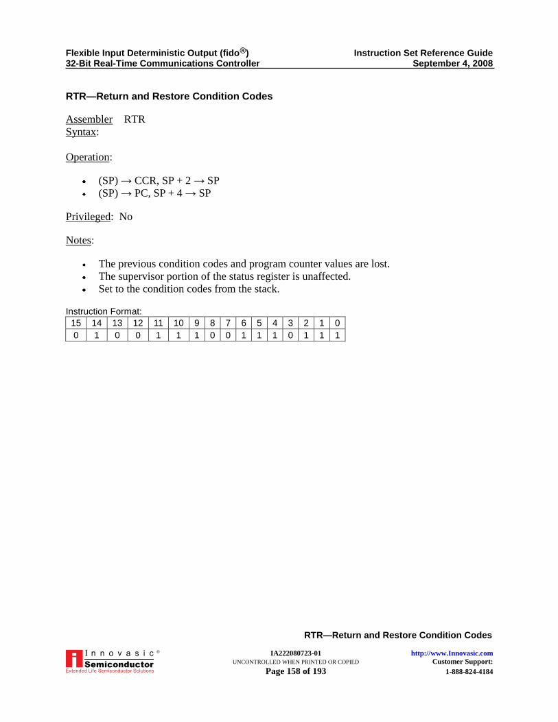
Flexible Input Deterministic Output (fido®) Instruction Set Reference Guide 32-Bit Real-Time Communications Controller September 4, 2008
IA222080723-01 http://www.Innovasic.com UNCONTROLLED WHEN PRINTED OR COPIED Customer Support: Page 158 of 193 1-888-824-4184
RTR—Return and Restore Condition Codes
®
RTR—Return and Restore Condition Codes
Assembler RTR
Syntax:
Operation:
(SP) → CCR, SP + 2 → SP
(SP) → PC, SP + 4 → SP
Privileged: No
Notes:
The previous condition codes and program counter values are lost.
The supervisor portion of the status register is unaffected.
Set to the condition codes from the stack.
Instruction Format: 15 14 13 12 11 10 9 8 7 6 5 4 3 2 1 0
0 1 0 0 1 1 1 0 0 1 1 1 0 1 1 1

Flexible Input Deterministic Output (fido®) Instruction Set Reference Guide 32-Bit Real-Time Communications Controller September 4, 2008
IA222080723-01 http://www.Innovasic.com UNCONTROLLED WHEN PRINTED OR COPIED Customer Support: Page 159 of 193 1-888-824-4184
RTS—Return from Subroutine
®
RTS—Return from Subroutine
Assembler RTS
Syntax:
Operation: (SP) → PC, SP + 4 → SP
Privileged: No
Notes:
Pulls the program counter value from the stack.
The previous program counter value is lost.
Condition Codes:
X—Not affected
N—Not affected
Z—Not affected
V—Not affected
C—Not affected
Instruction Format: 15 14 13 12 11 10 9 8 7 6 5 4 3 2 1 0
0 1 0 0 1 1 1 0 0 1 1 1 0 1 0 1

Flexible Input Deterministic Output (fido®) Instruction Set Reference Guide 32-Bit Real-Time Communications Controller September 4, 2008
IA222080723-01 http://www.Innovasic.com UNCONTROLLED WHEN PRINTED OR COPIED Customer Support: Page 160 of 193 1-888-824-4184
SBCD—Subtract Decimal with Extend
®
SBCD—Subtract Decimal with Extend
Assembler SBCD Dx, Dy
Syntax: SBCD –(Ax), –(Ay)
Operation: Destination10 − Source10 − X Bit → Destination
Attributes: Size = byte
Privileged: No
Condition Codes:
X—Set same as Carry Bit
N—Undefined
Z—Cleared if result is non-zero; unchanged otherwise
V—Undefined
C—Set if decimal borrow was generated; cleared otherwise
Note: Normal programming use of this instruction is to set the Z Bit prior to
performing this operation, allowing this bit to be tested during multi-
precision operations.
Instruction Format: 15 14 13 12 11 10 9 8 7 6 5 4 3 2 1 0
1 0 0 0 Destination Register 1 0 1 1 1 R/M Source Register
Where:
Destination Register—Specifies either a data or an address register as the location of the
destination operand.
R/M:
– 0—Operands are addresses as Dn,Dn
– 1—Operands are addresses as -(An),-(An)
Source Register—Specifies either a data or an address register as the location of the
source operand.
This instruction only uses two addressing Modes (determined by the R/M Bit):
Data register direct: Dn,Dn (both source and destination are data registers).
Address register indirect with predecrement: -(An),-(An) (both source and destination are
pointed to by address registers).

Flexible Input Deterministic Output (fido®) Instruction Set Reference Guide 32-Bit Real-Time Communications Controller September 4, 2008
IA222080723-01 http://www.Innovasic.com UNCONTROLLED WHEN PRINTED OR COPIED Customer Support: Page 161 of 193 1-888-824-4184
SCC—Set According to Condition Code
®
SCC—Set According to Condition Code
Assembler SCC <ea>
Syntax:
Operation: If (condition true) then set destination, else clear destination
Attributes: Size = byte
Privileged: No
Notes: If specified condition is true, sets all bits in the specified destination byte to a ―1‖
(TRUE); otherwise clears all the bits to ―0‖ (FALSE).
Condition Codes:
X—Not affected N—Not affected Z—Not affected V—Not affected C—Not affected
Instruction Format: 15 14 13 12 11 10 9 8 7 6 5 4 3 2 1 0
Op-Code Effective Address
0 1 0 1 Condition 1 1 Mode Register

Flexible Input Deterministic Output (fido®) Instruction Set Reference Guide 32-Bit Real-Time Communications Controller September 4, 2008
IA222080723-01 http://www.Innovasic.com UNCONTROLLED WHEN PRINTED OR COPIED Customer Support: Page 162 of 193 1-888-824-4184
SCC—Set According to Condition Code
®
Where:
Condition—Specifies a conditional test according to the table below:
Condition Mnemonic Condition Code Description Details
CC SCC 0100 Carry Clear ―!C‖
CS SCS 0101 Carry Set ―C‖
EQ SEQ 0111 Equal ―Z‖
F SF 0001 Never Equal 0
GE SGE 1100 Greater or Equal ―N&V;!N&!V‖
GT SGT 1110 Greater Than ―N&V&!Z;!N&!V&!Z‖
HI SHI 0010 High ―!C&!Z‖
LE SLE 1111 Less or Equal ―Z;N&!V;!N&V‖
LS SLS 0011 Low or Same ―!C;!Z‖
LT SLT 1101 Less Than ―N&!V;!N&V‖
MI SMI 1011 Minus ―N‖
NE SNE 0110 Not Equal ―!Z‖
PL SPL 1010 Plus ―!N‖
T ST 0000 Always True 1
VC SVC 1000 Overflow Clear ―!V‖
VS SVS 1001 Overflow Set ―V‖
Effective-Address fields are as per Instruction Single Word Format and address mode
tables (see Table 2, Core Addressing Modes Summary) and always indicate the
destination operand.
Addressing modes for destination operand: Addressing Mode Mode Field Register Field Applies? Notes
Dn 000 N Yes –
An 001 N – –
(An) 010 N Yes –
(An)+ 011 N Yes –
-(An) 100 N Yes –
(d16,An) 101 N Yes –
(d8,An,Xn.Size*Scale) 110 N Yes –
(bd,An,Xn.Size*Scale) 110 N Yes –
(d16,PC) 111 010 – –
(d8,PC,Xn.Size*Scale) 111 011 – –
(bd,PC,Xn.Size*Scale) 111 011 – –
(xxx).W 111 000 Yes –
(xxx).L 111 001 Yes –
#xxx 111 100 – –

Flexible Input Deterministic Output (fido®) Instruction Set Reference Guide 32-Bit Real-Time Communications Controller September 4, 2008
IA222080723-01 http://www.Innovasic.com UNCONTROLLED WHEN PRINTED OR COPIED Customer Support: Page 163 of 193 1-888-824-4184
SLEEP—Sleep Current Context
®
SLEEP—Sleep Current Context
Assembler SLEEP
Syntax:
Operation: Sleep the current context.
Privileged: Yes
Notes:
The PC is advanced to point to the next instruction.
Change current context’s READY status to NOT READY.
– The CMU is expected to give CPU control to a higher priority context, therefore this
context will stop fetching and executing instructions. It is possible that no other
higher priority contexts are READY. In this case, the entire CPU could enter a sleep
state to save power.
Processing for this context resumes when:
– An interrupt assigned to this context occurs (it will be marked READY and the
context’s priority will determine when it runs).
– This context is ―manually‖ marked READY by Master Context_0 (MC0) (the relative
priority of this context applies).
Condition Codes:
X—Not affected
N—Not affected
Z—Not affected
V—Not affected
C—Not affected
Instruction Format: 15 14 13 12 11 10 9 8 7 6 5 4 3 2 1 0
0 1 0 0 1 1 1 0 0 1 1 1 1 0 0 0

Flexible Input Deterministic Output (fido®) Instruction Set Reference Guide 32-Bit Real-Time Communications Controller September 4, 2008
IA222080723-01 http://www.Innovasic.com UNCONTROLLED WHEN PRINTED OR COPIED Customer Support: Page 164 of 193 1-888-824-4184
STOP—Load Status Register and Stop
®
STOP—Load Status Register and Stop
Assembler STOP #<data>
Syntax:
Operation:
Immediate data → SR
STOP
Attributes: Size = word
Privileged: Yes
Notes:
Immediate data is loaded into the entire status register.
The PC is advanced to point to the next instruction.
When executed from the Master Context_0:
– All contexts are moved to the NOT READY state (if in the READY STATE) or
remain HALT-ed.
– The clock to the CPU core is HALT-ed (clocks to onboard peripherals continue).
When executed from any other context, that context is moved to the NOT READY state,
but no change is made to clock operation (equivalent to executing the SLEEP instruction
except that the status register is updated).
Processing resumes when a trace, interrupt, or reset exception occurs:
– A trace exception occurs if the trace state is enabled when the STOP instruction is
executed. This is for single-step mode using CPU32 Trace.
– If an interrupt with higher priority than that of the new SR occurs, an interrupt
exception occurs.
– An external reset always initiates reset exception processing.
Condition Codes:
X—Set according to the immediate operand
N—Set according to the immediate operand
Z—Set according to the immediate operand
V—Set according to the immediate operand
C—Set according to the immediate operand

Flexible Input Deterministic Output (fido®) Instruction Set Reference Guide 32-Bit Real-Time Communications Controller September 4, 2008
IA222080723-01 http://www.Innovasic.com UNCONTROLLED WHEN PRINTED OR COPIED Customer Support: Page 165 of 193 1-888-824-4184
STOP—Load Status Register and Stop
®
Instruction Format: 15 14 13 12 11 10 9 8 7 6 5 4 3 2 1 0
0 1 0 0 1 1 1 0 0 1 1 1 0 0 1 0
Immediate Data

Flexible Input Deterministic Output (fido®) Instruction Set Reference Guide 32-Bit Real-Time Communications Controller September 4, 2008
IA222080723-01 http://www.Innovasic.com UNCONTROLLED WHEN PRINTED OR COPIED Customer Support: Page 166 of 193 1-888-824-4184
SUB—Subtract
®
SUB—Subtract
Assembler SUB <ea>, Dn
SUB Dn, <ea>
Syntax:
Operation: Destination − Source → Destination
Attributes: Size = byte, word or long
Privileged: No
Condition Codes:
X—Set same as Carry Bit
N—Set if result is negative; cleared otherwise
Z—Set if result is zero; cleared otherwise
V—Set if overflow is generated; cleared otherwise
C—Set if borrow was generated; cleared otherwise
Instruction Format: 15 14 13 12 11 10 9 8 7 6 5 4 3 2 1 0
Op-Code Effective Address
1 0 0 1 Register Opmode Mode Register
Where:
Register Field—Specifies any one of the eight data registers.
Opmode Field—Specifies whether the effective address is the source or the destination as
follows:
Operation Byte Word Long
(EA)—(Dn) → (Dn) 000 001 010
(Dn)—(EA) → (EA) 100 101 110
Effective-Address fields are as per Instruction Single Word Format and address mode
tables (see Table 11, Core Addressing Modes Summary).

Flexible Input Deterministic Output (fido®) Instruction Set Reference Guide 32-Bit Real-Time Communications Controller September 4, 2008
IA222080723-01 http://www.Innovasic.com UNCONTROLLED WHEN PRINTED OR COPIED Customer Support: Page 167 of 193 1-888-824-4184
SUB—Subtract
®
Addressing modes for source operand:
Addressing Mode Mode Field Register Field Applies? Notes
Dn 000 N Yes –
An 001 N Yes Word and long word only
(An) 010 N Yes –
(An)+ 011 N Yes –
-(An) 100 N Yes –
(d16,An) 101 N Yes –
(d8,An,Xn.Size*Scale) 110 N Yes –
(bd,An,Xn.Size*Scale) 110 N Yes –
(d16,PC) 111 010 Yes –
(d8,PC,Xn.Size*Scale) 111 011 Yes –
(bd,PC,Xn.Size*Scale) 111 011 Yes –
(xxx).W 111 000 Yes –
(xxx).L 111 001 Yes –
#xxx 111 100 Yes SUBI or SUBQ are used if the source is immediate data.
Addressing modes for destination operand:
Addressing Mode Mode Field Register Field Applies? Notes
Dn 000 N – –
An 001 N – SUBA is used when the destination is an address register.
(An) 010 N Yes –
(An)+ 011 N Yes –
-(An) 100 N Yes –
(d16,An) 101 N Yes –
(d8,An,Xn.Size*Scale) 110 N Yes –
(bd,An,Xn.Size*Scale) 110 N Yes –
(d16,PC) 111 010 – –
(d8,PC,Xn.Size*Scale) 111 011 – –
(bd,PC,Xn.Size*Scale) 111 011 – –
(xxx).W 111 000 Yes –
(xxx).L 111 001 Yes –
#xxx 111 100 – –

Flexible Input Deterministic Output (fido®) Instruction Set Reference Guide 32-Bit Real-Time Communications Controller September 4, 2008
IA222080723-01 http://www.Innovasic.com UNCONTROLLED WHEN PRINTED OR COPIED Customer Support: Page 168 of 193 1-888-824-4184
SUBA—Subtract Address
®
SUBA—Subtract Address
Assembler SUBA <ea>, An
Syntax:
Operation: Destination − Source → Destination
Attributes: Size = word or long
Privileged: No
Condition Codes:
X—Not affected
N—Not affected
Z—Not affected
V—Not affected
C—Not affected
Instruction Format: 15 14 13 12 11 10 9 8 7 6 5 4 3 2 1 0
Op-Code Effective Address
1 0 0 1 Register Opmode Mode Register
Where:
Register Field—Specifies any one of the eight address registers. This is always the
destination.
Opmode Field—Specifies the size of the operand:
– 011—Word operation. The source operand is sign-extended to a long and the
operation is performed on the address register using all 32 bits.
– 111—Long operation.
Effective-Address fields are as per Instruction Single Word Format and address mode
tables (see Table 2, Core Addressing Modes Summary) which always indicate the source
operand.

Flexible Input Deterministic Output (fido®) Instruction Set Reference Guide 32-Bit Real-Time Communications Controller September 4, 2008
IA222080723-01 http://www.Innovasic.com UNCONTROLLED WHEN PRINTED OR COPIED Customer Support: Page 169 of 193 1-888-824-4184
SUBA—Subtract Address
®
Addressing modes for source operand: Addressing Mode Mode Field Register Field Applies? Notes
Dn 000 N Yes –
An 001 N Yes –
(An) 010 N Yes –
(An)+ 011 N Yes –
-(An) 100 N Yes –
(d16,An) 101 N Yes –
(d8,An,Xn.Size*Scale) 110 N Yes –
(bd,An,Xn.Size*Scale) 110 N Yes –
(d16,PC) 111 010 Yes –
(d8,PC,Xn.Size*Scale) 111 011 Yes –
(bd,PC,Xn.Size*Scale) 111 011 Yes –
(xxx).W 111 000 Yes –
(xxx).L 111 001 Yes –
#xxx 111 100 Yes –

Flexible Input Deterministic Output (fido®) Instruction Set Reference Guide 32-Bit Real-Time Communications Controller September 4, 2008
IA222080723-01 http://www.Innovasic.com UNCONTROLLED WHEN PRINTED OR COPIED Customer Support: Page 170 of 193 1-888-824-4184
SUBI—Subtract Immediate
®
SUBI—Subtract Immediate
Assembler SUBI #<data>, <ea>
Syntax:
Operation: Destination − Immediate Data → Destination
Attributes: Size = byte, word or long
Privileged: No
Condition Codes:
X—Set same as Carry Bit
N—Set if result is negative; cleared otherwise
Z—Set if result is zero; cleared otherwise
V—Set if overflow is generated; cleared otherwise
C—Set if borrow was generated; cleared otherwise
Instruction Format: 15 14 13 12 11 10 9 8 7 6 5 4 3 2 1 0
0 0 0 0 0 1 0 0 Size Mode Register
Word Data (16-bits) Byte Data (8-bits)
Long Data (32-bits)
Where:
Size Field (size of immediate data must match operand size):
– 00—Byte operation → data is low-order byte of immediate word
– 01—Word operation → data is the entire immediate word
– 10—Long operation → data is in the next two immediate words

Flexible Input Deterministic Output (fido®) Instruction Set Reference Guide 32-Bit Real-Time Communications Controller September 4, 2008
IA222080723-01 http://www.Innovasic.com UNCONTROLLED WHEN PRINTED OR COPIED Customer Support: Page 171 of 193 1-888-824-4184
SUBI—Subtract Immediate
®
Addressing modes for destination operand: Addressing Mode Mode Field Register Field Applies? Notes
Dn 000 N Yes –
An 001 N – –
(An) 010 N Yes –
(An)+ 011 N Yes –
-(An) 100 N Yes –
(d16,An) 101 N Yes –
(d8,An,Xn.Size*Scale) 110 N Yes –
(bd,An,Xn.Size*Scale) 110 N Yes –
(d16,PC) 111 010 – –
(d8,PC,Xn.Size*Scale) 111 011 – –
(bd,PC,Xn.Size*Scale) 111 011 – –
(xxx).W 111 000 Yes –
(xxx).L 111 001 Yes –
#xxx 111 100 – –

Flexible Input Deterministic Output (fido®) Instruction Set Reference Guide 32-Bit Real-Time Communications Controller September 4, 2008
IA222080723-01 http://www.Innovasic.com UNCONTROLLED WHEN PRINTED OR COPIED Customer Support: Page 172 of 193 1-888-824-4184
SUBQ—Subtract Quick
®
SUBQ—Subtract Quick
Assembler SUBQ #<data>, <ea>
Syntax:
Operation:
Destination − Immediate Data → Destination
– Immediate data is stored as a part of the instruction word (3 bits) and can range from
1 to 8.
Attributes:
Size = byte, word or long
– When the destination operand is a data register or is in memory, the size can be byte,
word, or long word.
– When the destination operand is an address register, the size is word or long word
only.
– When subtracting from address registers, the Condition Codes are not altered and the
entire register is used regardless of operand size.
Privileged: No
Condition Codes:
X—Set same as Carry Bit
N—Set if result is negative; cleared otherwise
Z—Set if result is zero; cleared otherwise
V—Set if overflow is generated; cleared otherwise
C—Set if borrow was generated; cleared otherwise
Note: When subtracting from address registers, the condition codes are not
altered.
Instruction Format: 15 14 13 12 11 10 9 8 7 6 5 4 3 2 1 0
Op-Code Effective Address
0 1 0 1 Data 1 Size Mode Register

Flexible Input Deterministic Output (fido®) Instruction Set Reference Guide 32-Bit Real-Time Communications Controller September 4, 2008
IA222080723-01 http://www.Innovasic.com UNCONTROLLED WHEN PRINTED OR COPIED Customer Support: Page 173 of 193 1-888-824-4184
SUBQ—Subtract Quick
®
Where:
Data Field—Specifies three bits of immediate data, with a value ranging from 1 to 8
(000 represents 8).
Size Field:
– 00—Byte operation
– 01—Word operation
– 10—Long-Word operation
Effective-Address fields are as per Instruction Single Word Format and address mode
tables (see Table 12, Core Addressing Modes Summary) and specify the destination
operand only.
Addressing modes for destination operand: Addressing Mode Mode Field Register Field Applies? Notes
Dn 000 N Yes –
An 001 N – –
(An) 010 N Yes –
(An)+ 011 N Yes –
-(An) 100 N Yes –
(d16,An) 101 N Yes –
(d8,An,Xn.Size*Scale) 110 N Yes –
(bd,An,Xn.Size*Scale) 110 N Yes –
(d16,PC) 111 010 – –
(d8,PC,Xn.Size*Scale) 111 011 – –
(bd,PC,Xn.Size*Scale) 111 011 – –
(xxx).W 111 000 Yes –
(xxx).L 111 001 Yes –
#xxx 111 100 – –

Flexible Input Deterministic Output (fido®) Instruction Set Reference Guide 32-Bit Real-Time Communications Controller September 4, 2008
IA222080723-01 http://www.Innovasic.com UNCONTROLLED WHEN PRINTED OR COPIED Customer Support: Page 174 of 193 1-888-824-4184
SUBX—Subtract Extended
®
SUBX—Subtract Extended
Assembler SUBX Dx, Dy
Syntax: SUBX –(Ax), –(Ay)
Operation: Destination − Source - X Bit → Destination
Attributes: Size = byte, word or long
Privileged: No
Condition Codes:
X—Set same as Carry Bit N—Set if result is negative; cleared otherwise Z—Cleared if result is non-zero; unchanged otherwise V—Set if overflow occurs; cleared otherwise C—Set if carry was generated; cleared otherwise
Note: Normal programming use of this instruction is to set the Z Bit prior to performing this operation. This allows this bit to be tested during multi-precision operations.
Instruction Format:
15 14 13 12 11 10 9 8 7 6 5 4 3 2 1 0
1 0 0 1 Destination Register 1 Size 0 0 R/M Source Register
Where:
Destination Register—Specifies either a data or an address register as the location of the destination operand.
Size Field: – 00—Byte operation – 01—Word operation and – 10—Long-Word operation
R/M Field: – 0—Operands are addresses as Dn,Dn – 1—Operands are addresses as -(An),-(An)
Source Register—Specifies either a data or an address register as the location of the source operand.

Flexible Input Deterministic Output (fido®) Instruction Set Reference Guide 32-Bit Real-Time Communications Controller September 4, 2008
IA222080723-01 http://www.Innovasic.com UNCONTROLLED WHEN PRINTED OR COPIED Customer Support: Page 175 of 193 1-888-824-4184
SUBX—Subtract Extended
®
This instruction only uses two addressing Modes (determined by the R/M Bit):
Data Register Direct—Dn,Dn (both source and destination are data registers). Address Register Indirect with Predecrement—-(An),-(An) (both source and destination
are pointed to by address registers).

Flexible Input Deterministic Output (fido®) Instruction Set Reference Guide 32-Bit Real-Time Communications Controller September 4, 2008
IA222080723-01 http://www.Innovasic.com UNCONTROLLED WHEN PRINTED OR COPIED Customer Support: Page 176 of 193 1-888-824-4184
SWAP—Swap Register Halves
®
SWAP—Swap Register Halves
Assembler SWAP Dn
Syntax:
Operation: Rn[31–16] ↔ Rn[15–0]
Privileged: No
See Figure 1, Shift and Rotate Instructions, for a comparison of syntax, operand size, and
operation of ASL/ASR, LSL/LSR, ROL/ROR, ROXL/ROXR, and SWAP instructions.
Condition Codes:
X—Not affected
N—Set if the most significant bit of the 32-bit result is set; cleared otherwise
Z—Set if the 32-bit result is zero; cleared otherwise
V—Always cleared
C—Always cleared
Instruction Format: 15 14 13 12 11 10 9 8 7 6 5 4 3 2 1 0
0 1 0 0 1 0 0 0 0 1 0 0 0 Register
Where:
Register Field—Specifies the data register to swap

Flexible Input Deterministic Output (fido®) Instruction Set Reference Guide 32-Bit Real-Time Communications Controller September 4, 2008
IA222080723-01 http://www.Innovasic.com UNCONTROLLED WHEN PRINTED OR COPIED Customer Support: Page 177 of 193 1-888-824-4184
TAS—Test and Set an Operand
®
TAS—Test and Set an Operand
Assembler TAS <ea>
Syntax:
Operation: Destination Tested → Condition Codes, 1 → [7] of Destination
Attributes: Size = byte
Privileged: No
Notes:
Tests the destination operand and sets the condition codes as described below.
TAS then sets the most significant bit of the byte operand to a one.
The operation uses a read/modify/write memory cycle that completes without
interruption.
This instruction supports the use of a flag to coordinate several processors.
Condition Codes:
X—Not affected
N—Set if the most significant bit of the operand is currently set; cleared otherwise
Z—Set if the operand was zero; cleared otherwise
V—Always cleared
C—Always cleared
Instruction Format: 15 14 13 12 11 10 9 8 7 6 5 4 3 2 1 0
Op-Code Effective Address
0 1 0 0 1 0 1 0 1 1 Mode Register
Where:
Effective-Address fields are as per Instruction Single Word Format and address mode
tables (see Table 2, Core Addressing Modes Summary) and always indicate the operand
to be tested and the destination.

Flexible Input Deterministic Output (fido®) Instruction Set Reference Guide 32-Bit Real-Time Communications Controller September 4, 2008
IA222080723-01 http://www.Innovasic.com UNCONTROLLED WHEN PRINTED OR COPIED Customer Support: Page 178 of 193 1-888-824-4184
TAS—Test and Set an Operand
®
Addressing modes for source operand:
Addressing Mode Mode Field Register Field Applies? Notes
Dn 000 N Yes –
An 001 N – –
(An) 010 N Yes –
(An)+ 011 N Yes –
-(An) 100 N Yes –
(d16,An) 101 N Yes –
(d8,An,Xn.Size*Scale) 110 N Yes –
(bd,An,Xn.Size*Scale) 110 N Yes –
(d16,PC) 111 010 – –
(d8,PC,Xn.Size*Scale) 111 011 – –
(bd,PC,Xn.Size*Scale) 111 011 – –
(xxx).W 111 000 Yes –
(xxx).L 111 001 Yes –
#xxx 111 100 – –

Flexible Input Deterministic Output (fido®) Instruction Set Reference Guide 32-Bit Real-Time Communications Controller September 4, 2008
IA222080723-01 http://www.Innovasic.com UNCONTROLLED WHEN PRINTED OR COPIED Customer Support: Page 179 of 193 1-888-824-4184
TRAP—Trap
®
TRAP—Trap
Assembler TRAP #<vector>
Syntax:
Operation:
SSP – 2 → SSP, Format/Offset → (SSP) SSP − 4 → SSP, PC → (SSP) SSP − 2 → SSP, SR → (SSP) Vector Address → PC
Privileged: No
Notes:
Causes a TRAP #(vector) exception. A vector number is generated by adding the immediate vector operand to 32. The range
of vector operand values is 0–15, thus there are 16 possible vector numbers (#32 to #47). This instruction shares these vectors with the TRAPX instruction.
Note: Care should be taken when allocating these resources.
The normal exception handling sequence is used: – Make internal copy of existing Status Register (SR) then modify the SR as follows:
o Set the S Bit establishing supervisor mode. o Clear the trace bits.
– Decrement Supervisor Stack Pointer (SSP) by two and push word containing stack frame format and vector offset onto the supervisor’s stack. The normal four-word stack frame format is used (stack frame format 0000). o CPU32 stack frames are described in The fido1100 User Guide, Section 4.6.4,
Interrupt, Fault, and Exception Handling. – Decrement Supervisor Stack Pointer (SSP) by four and push long word containing the
32-bit PC onto the supervisor’s stack. – Decrement Supervisor Stack Pointer (SSP) by two and push word containing status
register onto the supervisor’s stack. – Fetch a long word from memory pointed to by the Trap Instruction Vector offset + the
VBR and place this in the PC. – Continue program execution at this location.

Flexible Input Deterministic Output (fido®) Instruction Set Reference Guide 32-Bit Real-Time Communications Controller September 4, 2008
IA222080723-01 http://www.Innovasic.com UNCONTROLLED WHEN PRINTED OR COPIED Customer Support: Page 180 of 193 1-888-824-4184
TRAP—Trap
®
Condition Codes:
X—Not affected N—Not affected Z—Not affected V—Not affected C—Not affected
Instruction Format: 15 14 13 12 11 10 9 8 7 6 5 4 3 2 1 0
0 1 0 0 1 1 1 0 0 1 0 0 Vector
Where:
Vector Field—Specifies the trap vector (0–15) to be taken.

Flexible Input Deterministic Output (fido®) Instruction Set Reference Guide 32-Bit Real-Time Communications Controller September 4, 2008
IA222080723-01 http://www.Innovasic.com UNCONTROLLED WHEN PRINTED OR COPIED Customer Support: Page 181 of 193 1-888-824-4184
TRAPCC—Trap on Condition
®
TRAPCC—Trap on Condition
Assembler TRAPCC
Syntax: TRAPCC.W #<data>
TRAPCC.L #<data>
Operation:
SSP − 4 → SSP, PC → (SSP), (Current PC)
SSP − 2 → SSP, Format/Offset → (SSP)
SSP − 4 → SSP, PC (adjusted) → (SSP), (PC for RTE instruction to return to)
SSP − 2 → SSP, SR → (SSP)
Vector Address → PC
Attributes: Unsized or Size = Word or long
Privileged: No
Notes:
If the specified condition is true, causes a TRAPCC exception (vector #7). If the
condition is not true, the processor performs a no-operation and instruction execution
continues at the next instruction.
The optional immediate data must be placed in the word(s) immediately following the
instruction word. This data is available to the exception handler.
The normal exception handling sequence (six-word stack frame) is used:
– Decrement Supervisor Stack Pointer (SSP) by four and push the current PC onto the
supervisor’s stack.
– Make internal copy of existing Status Register (SR) then modify the SR as follows:
o Set the S Bit establishing supervisor mode.
o Clear the trace bits.
o Decrement Supervisor Stack Pointer (SSP) by two and push word containing
stack frame format and vector offset onto the supervisor’s stack. The normal six-
word stack frame format is used (stack frame format 0010).
o CPU32 Stack frames are described in The fido1100 User Guide, Section 4.6.4,
Interrupt, Fault, and Exception Handling.
– Decrement Supervisor Stack Pointer (SSP) by four and push long word containing the
32-bit PC (address of the next instruction to execute upon RTE) onto the supervisor’s
stack.
– Decrement Supervisor Stack Pointer (SSP) by two and push word containing status
register onto the supervisor’s stack.
– Fetch a long word from memory pointed to by the TRAPCC Instruction Vector offset
+ the VBR and place this in the PC.

Flexible Input Deterministic Output (fido®) Instruction Set Reference Guide 32-Bit Real-Time Communications Controller September 4, 2008
IA222080723-01 http://www.Innovasic.com UNCONTROLLED WHEN PRINTED OR COPIED Customer Support: Page 182 of 193 1-888-824-4184
TRAPCC—Trap on Condition
®
– Continue program execution at this location.
Condition Codes:
X—Not affected
N—Not affected
Z—Not affected
V—Not affected
C—Not affected
Instruction Format: 15 14 13 12 11 10 9 8 7 6 5 4 3 2 1 0
0 1 0 1 Condition 1 1 1 1 1 Opmode
Optional Word
Optional Long Word
Where:
Condition—Specifies a conditional test according to the table below:
Condition Mnemonic Condition Code Description Details
CC SCC 0100 Carry Clear ―!C‖
CS SCS 0101 Carry Set ―C‖
EQ SEQ 0111 Equal ―Z‖
F SF 0001 Never Equal 0
GE SGE 1100 Greater or Equal ―N&V;!N&!V‖
GT SGT 1110 Greater Than ―N&V&!Z;!N&!V&!Z‖
HI SHI 0010 High ―!C&!Z‖
LE SLE 1111 Less or Equal ―Z;N&!V;!N&V‖
LS SLS 0011 Low or Same ―!C;!Z‖
LT SLT 1101 Less Than ―N&!V;!N&V‖
MI SMI 1011 Minus ―N‖
NE SNE 0110 Not Equal ―!Z‖
PL SPL 1010 Plus ―!N‖
T ST 0000 Always True 1
VC SVC 1000 Overflow Clear ―!V‖
VS SVS 1001 Overflow Set ―V‖
Opmode—Specifies the instruction form:
– 010—Instruction is followed by a word-sized operand
– 011—Instruction is followed by a long-word-sized operand
– 100—Instruction has no operand

Flexible Input Deterministic Output (fido®) Instruction Set Reference Guide 32-Bit Real-Time Communications Controller September 4, 2008
IA222080723-01 http://www.Innovasic.com UNCONTROLLED WHEN PRINTED OR COPIED Customer Support: Page 183 of 193 1-888-824-4184
TRAPV—If V then Trap
®
TRAPV—If V then Trap
Assembler TRAPV
Syntax:
Operation:
SSP − 4 → SSP, PC → (SSP), (Current PC)
SSP − 2 → SSP, Format/Offset → (SSP)
SSP − 4 → SSP, PC (adjusted) → (SSP), (PC for RTE instruction to return to)
SSP − 2 → SSP, SR → (SSP)
Vector Address → PC
Privileged: No
Notes:
If the CCR overflow bit is set, causes a TRAPV exception (vector #7). If the bit is not
set, the processor performs a no-operation and instruction execution continues at the next
instruction.
The normal exception handling sequence (six-word stack frame) is used:
– Decrement Supervisor Stack Pointer (SSP) by four and push the current PC onto the
supervisor’s stack.
– Make internal copy of existing Status Register (SR) then modify the SR as follows:
o Set the S Bit establishing supervisor mode.
o Clear the trace bits.
– Decrement Supervisor Stack Pointer (SSP) by two and push word containing stack
frame format and vector offset onto the supervisor’s stack. The normal six-word
stack frame format is used (stack frame format 0010).
o CPU32 Stack frames are described in The fido1100 User Guide, Section 4.6.4,
Interrupt, Fault, and Exception Handling.
– Decrement Supervisor Stack Pointer (SSP) by four and push long word containing the
32-bit PC (address of the next instruction to execute upon RTE) onto the supervisor’s
stack.
– Decrement Supervisor Stack Pointer (SSP) by two and push word containing status
register onto the supervisor’s stack.
– Fetch a long word from memory pointed to by the TRAPV Instruction Vector offset +
the VBR and place this in the PC.
– Continue program execution at this location.

Flexible Input Deterministic Output (fido®) Instruction Set Reference Guide 32-Bit Real-Time Communications Controller September 4, 2008
IA222080723-01 http://www.Innovasic.com UNCONTROLLED WHEN PRINTED OR COPIED Customer Support: Page 184 of 193 1-888-824-4184
TRAPV—If V then Trap
®
Condition Codes:
X—Not affected
N—Not affected
Z—Not affected
V—Not affected
C—Not affected
Instruction Format: 15 14 13 12 11 10 9 8 7 6 5 4 3 2 1 0
0 1 0 0 1 1 1 0 0 1 1 1 0 1 1 0

Flexible Input Deterministic Output (fido®) Instruction Set Reference Guide 32-Bit Real-Time Communications Controller September 4, 2008
IA222080723-01 http://www.Innovasic.com UNCONTROLLED WHEN PRINTED OR COPIED Customer Support: Page 185 of 193 1-888-824-4184
TRAPX—Trap to Master Context_0
®
TRAPX—Trap to Master Context_0
Assembler TRAPX #n (n = 96 to 111)
Syntax:
This instruction, unique to the Innovasic fido series of communications controllers, provides a
fast (no stack operations) communications mechanism between Context_1 through Context_4
and the Master Context_0 (MC0). The net effect is that the trapping context is left ready to
execute at the instruction following the trap, while the master context is executing at the
corresponding vector.
Note: This instruction generates an exception classified as an “Interrupt”
and, therefore, will generate a stack frame only if the targeted context is set
to Standard Interrupt Mode, as defined by the Context Control Registers.
Otherwise, this exception will not generate a stack frame and the exception
handler will only have the faulted context ID to tell it what happened. This
means that all 16 forms of the TRAPX #n instruction are the same when in
this mode.
Operation:
Context ID − Faulted Context Register
Switch to Context_0 (leaving current context in READY state)
Vector Address → PC
Begin execution as MC0
Privileged: No
Notes:
Causes a TRAPX #n exception (vectors 96 thru 111) to be passed to Master Context_0
(MC0).
Normal use of this instruction will be from a non-master context (Context_1 through
Context_4). Using this instruction from Context_0 will cause a non-returnable vector
branch.
The calling context ID will be placed in the Faulted Context Register for the MC0 to
examine.
After this instruction executes, because the Master Context_0 (MCO) is marked READY,
it will immediately run.
This instruction can coordinate action between contexts. It can be used as a
message-passing technique or used to raise exceptions occurring in a user

Flexible Input Deterministic Output (fido®) Instruction Set Reference Guide 32-Bit Real-Time Communications Controller September 4, 2008
IA222080723-01 http://www.Innovasic.com UNCONTROLLED WHEN PRINTED OR COPIED Customer Support: Page 186 of 193 1-888-824-4184
TRAPX—Trap to Master Context_0
®
context to the master context.
A vector number is generated by adding the immediate vector operand to 96. The range
of vector operand values is 0–15, thus there are 16 possible vector numbers (#96 to #111).
The Faulted Context Register is updated to indicate to the MC0 which context raised this
exception.
Current context is set to MC0.
Fetch a long word from memory pointed to by the TRAP Instruction Vector offset + the
VBR (of MC0) and place this in the PC.
MC0 is set to the READY state and program execution continues at this location (as
MC0).
Condition Codes:
X—Not affected
N—Not affected
Z—Not affected
V—Not affected
C—Not affected
Instruction Format: 15 14 13 12 11 10 9 8 7 6 5 4 3 2 1 0
0 1 0 0 1 1 1 0 0 0 1 1 Vector
Where:
Vector Field—Specifies the trap vector (0–15) to be taken.

Flexible Input Deterministic Output (fido®) Instruction Set Reference Guide 32-Bit Real-Time Communications Controller September 4, 2008
IA222080723-01 http://www.Innovasic.com UNCONTROLLED WHEN PRINTED OR COPIED Customer Support: Page 187 of 193 1-888-824-4184
TST—Test an Operand
®
TST—Test an Operand
Assembler TST <ea>
Syntax:
Operation: Destination Tested → Condition Codes
Attributes: Size = byte, word, or long
Privileged: No
Notes: Compares the destination operand to zero and sets the condition codes listed below.
Condition Codes:
X—Not affected
N—Set if the operand is negative; cleared otherwise
Z—Set if the operand is zero; cleared otherwise
V—Always cleared
C—Always cleared
Instruction Format: 15 14 13 12 11 10 9 8 7 6 5 4 3 2 1 0
Op-Code Effective Address
0 1 0 0 1 0 1 0 Size Mode Register
Where:
Size—Specifies the size of the operation:
– 00—Byte operation
– 01—Word operation
– 10—Long-Word operation
Effective-Address fields are as per Instruction Single Word Format and address mode
tables (see Table 2, Core Addressing Modes Summary) and always indicate the operand
to be tested.

Flexible Input Deterministic Output (fido®) Instruction Set Reference Guide 32-Bit Real-Time Communications Controller September 4, 2008
IA222080723-01 http://www.Innovasic.com UNCONTROLLED WHEN PRINTED OR COPIED Customer Support: Page 188 of 193 1-888-824-4184
TST—Test an Operand
®
Addressing modes for source operand: Addressing Mode Mode Field Register Field Applies? Notes
Dn 000 N Yes –
An 001 N Yes Word or long-word operation only
(An) 010 N Yes –
(An)+ 011 N Yes –
-(An) 100 N Yes –
(d16,An) 101 N Yes –
(d8,An,Xn.Size*Scale) 110 N Yes –
(bd,An,Xn.Size*Scale) 110 N Yes –
(d16,PC) 111 010 Yes –
(d8,PC,Xn.Size*Scale) 111 011 Yes –
(bd,PC,Xn.Size*Scale) 111 011 Yes –
(xxx).W 111 000 Yes –
(xxx).L 111 001 Yes –
#xxx 111 100 Yes –

Flexible Input Deterministic Output (fido®) Instruction Set Reference Guide 32-Bit Real-Time Communications Controller September 4, 2008
IA222080723-01 http://www.Innovasic.com UNCONTROLLED WHEN PRINTED OR COPIED Customer Support: Page 189 of 193 1-888-824-4184
UNLK—Unlink
®
UNLK—Unlink
Assembler UNLK An
Syntax:
Operation: An → SP, (SP) → An, SP + 4 → SP
Privileged: No
Notes: Loads the Stack Pointer value from the specified address register. Then loads the address
register with the long word pulled from the stack.
Condition Codes:
X—Not affected
N—Not affected
Z—Not affected
V—Not affected
C—Not affected
Instruction Format: 15 14 13 12 11 10 9 8 7 6 5 4 3 2 1 0
0 1 0 0 1 1 1 0 0 1 1 1 1 Register
Where:
Register Field—Specifies the address register for the instruction.

Flexible Input Deterministic Output (fido®) Instruction Set Reference Guide 32-Bit Real-Time Communications Controller September 4, 2008
IA222080723-01 http://www.Innovasic.com UNCONTROLLED WHEN PRINTED OR COPIED Customer Support: Page 190 of 193 1-888-824-4184
®
3. For Additional Information
The fido1100 User Guide and as well as other helpful tools and files are available. For example,
the GDB debugger supports both profiling and tracing of executing code.
When building a prototype using the fido1100 communications controller, a file in the
―Samples‖ directory can assist in customizing the software for a specific design.
The Innovasic Support Team wants our information to be complete, accurate, useful, and easy to
understand. Please feel free to contact our experts at Innovasic at any time with suggestions,
comments, or questions.
Innovasic Support Team
3737 Princeton NE
Suite 130
Albuquerque, NM 87107
(505) 883-5263
Fax: (505) 883-5477
Toll Free: (888) 824-4184
E-mail: [email protected]
Website: http://www.Innovasic.com

Flexible Input Deterministic Output (fido®) Instruction Set Reference Guide 32-Bit Real-Time Communications Controller September 4, 2008
IA222080723-01 http://www.Innovasic.com UNCONTROLLED WHEN PRINTED OR COPIED Customer Support: Page 191 of 193 1-888-824-4184
®
INDEX
A
ABCD—Add Decimal
with Extend ..................................... 10, 19
ADDA—Add Address ........................ 22, 23
ADD—Add ........................................... 8, 21
ADDI—Add Immediate...................... 22, 25
ADDQ—Add Quick ........................... 22, 27
ADDX—Add Extended ........................ 9, 29
AND—And ........................................... 9, 31
ANDI to CCR—And
Immediate to Condition
Code Register ........................................ 35
ANDI to SR—And
Immediate to Status
Register ................................................. 36
ANDI—And Immediate.................. 9, 32, 33
ASL/ASR—Arithmetic
Shift ................................................... 9, 37
B
BCC—Branch
Conditionally ........................................ 41
BCHG—Test a Bit and
Change .............................................. 9, 43
BCLR—Test a Bit and
Clear .................................................. 9, 46
BGND—Enter
Background Mode ................................. 49
BKPT—Software
Breakpoint ............................................. 50
BRA—Branch Always .............................. 51
BSET—Test a Bit and Set ..................... 9, 52
BSR—Branch to
Subroutine ............................................. 55
BTST—Test a Bit ................................. 9, 57
C
CHK2—Check Register
Against Bounds ............................... 61, 67
CHK—Check Register
Against Bounds ............................... 59, 61
CLR—Clear an Operand....................... 8, 63
CMP2—Compare
Register Against
Bounds .............................................. 8, 67
CMPA—Compare
Address ................................................. 69
CMP—Compare ................................... 8, 65
CMPI—Compare Immediate ...................................... 66, 71
CMPM—Compare
Memory ............................................. 8, 73
D
DBCC—Test Condition,
Decrement and Branch .......................... 74
DIVS/DIVSL—Signed
Divide ................................................ 8, 76
DIVU/DIVUL—Unsigned
Divide ................................................ 8, 79
E
EOR—Exclusive OR ............................ 9, 82
EORI to CCR—Exclusive
OR Immediate to
Condition Code
Register ................................................. 86
EORI to SR—Exclusive
OR Immediate to Status
Register ................................................. 87
EORI—Exclusive OR
Immediate ......................................... 9, 84
EXG—Exchange
Registers ............................................ 8, 88

Flexible Input Deterministic Output (fido®) Instruction Set Reference Guide 32-Bit Real-Time Communications Controller September 4, 2008
IA222080723-01 http://www.Innovasic.com UNCONTROLLED WHEN PRINTED OR COPIED Customer Support: Page 192 of 193 1-888-824-4184
®
EXT/EXTB—Sign
Extend ................................................... 90
I
ILLEGAL—Take Illegal
Instruction Trap ..................................... 91
J
JMP—Jump............................................... 92
JSR—Jump to Subroutine ......................... 93
L
LEA—Load Effective
Address ............................................. 8, 95
LINK—Link and Allocate .................... 8, 97
LPSTOP—Low Power
Stop ....................................................... 99
LSL/LSR—Logical Shift .................... 9, 100
M
MOVE from CCR—Move
Data from the
Condition Code
Register ................................................119
MOVE from SR—Move
Data from the Status
Register ............................................... 123
MOVE to CCR—Move
Data to Condition Code
Register ............................................... 121
MOVE USP—Move User
Stack Pointer ....................................... 125
MOVEA—Move Data
from Source to
Destination Address
Register ........................................... 8, 106
MOVEC—Move Control
Register ............................................... 108
MOVEM—Move
Multiple Registers ............................8, 110
MOVE—Move Data from
Source to Destination ...................... 8, 104
MOVEP—Move
Peripheral Data ................................8, 114
MOVEQ—Move Quick .......................8, 116
MOVES—Move Address
Space ....................................................117
MULS—Signed Multiply ................... 8, 126
MULU—Unsigned
Multiply .......................................... 8, 129
N
NBCD—Negate Decimal
with Extend ................................... 10, 132
NEG—Negate ..................................... 8, 134
NEGX—Negate with
Extend ............................................. 9, 136
NOP—No Operation ......................... 50, 138
NOT—Logical
Complement .................................... 9, 139
O
ORI to CCR—Inclusive
OR Immediate to
Condition Code
Register ............................................... 145
ORI to SR—Inclusive OR
Immediate to Status
Register ............................................... 146
ORI—Inclusive OR
Immediate ............................... 9, 142, 143
OR—Inclusive Logical
OR ................................................... 9, 141
P
PEA—Push Effective
Address ........................................... 8, 147
R
RESET—Reset External
Devices ................................................ 149
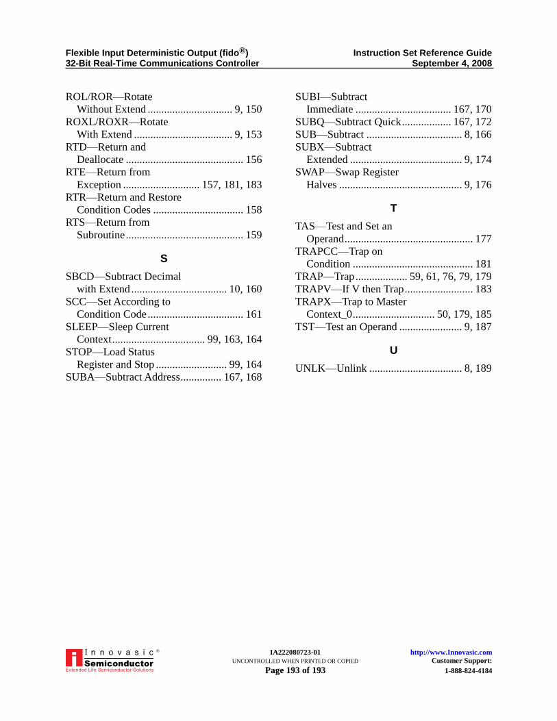
Flexible Input Deterministic Output (fido®) Instruction Set Reference Guide 32-Bit Real-Time Communications Controller September 4, 2008
IA222080723-01 http://www.Innovasic.com UNCONTROLLED WHEN PRINTED OR COPIED Customer Support: Page 193 of 193 1-888-824-4184
®
ROL/ROR—Rotate
Without Extend ............................... 9, 150
ROXL/ROXR—Rotate
With Extend .................................... 9, 153
RTD—Return and
Deallocate ........................................... 156
RTE—Return from
Exception ............................ 157, 181, 183
RTR—Return and Restore
Condition Codes ................................. 158
RTS—Return from
Subroutine ........................................... 159
S
SBCD—Subtract Decimal
with Extend ................................... 10, 160
SCC—Set According to
Condition Code ................................... 161
SLEEP—Sleep Current
Context .................................. 99, 163, 164
STOP—Load Status
Register and Stop .......................... 99, 164
SUBA—Subtract Address ............... 167, 168
SUBI—Subtract
Immediate ................................... 167, 170
SUBQ—Subtract Quick .................. 167, 172
SUB—Subtract ................................... 8, 166
SUBX—Subtract
Extended ......................................... 9, 174
SWAP—Swap Register
Halves ............................................. 9, 176
T
TAS—Test and Set an
Operand ............................................... 177
TRAPCC—Trap on
Condition ............................................ 181
TRAP—Trap ................... 59, 61, 76, 79, 179
TRAPV—If V then Trap ......................... 183
TRAPX—Trap to Master
Context_0 .............................. 50, 179, 185
TST—Test an Operand ....................... 9, 187
U
UNLK—Unlink .................................. 8, 189


![Instruction Set Reference [by Bradley]](https://img.dokumen.tips/doc/110x75/577d2faf1a28ab4e1eb258f2/instruction-set-reference-by-bradley.jpg)


![Instruction set reference [by allen bradley]](https://img.dokumen.tips/doc/110x75/55557d7eb4c9058a5a8b51d0/instruction-set-reference-by-allen-bradley.jpg)


